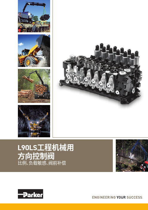
[小学教育]Parker负载敏感阀培训L90LS
派克汉尼汾工程机械用方向控制阀 L90LS 商品说明书
样本信息未使用本文所述之产品及相关项目选择不当或使用不当可能会造成人员死亡、警告样本布局除一般信息和基本技术数据外,该样本还对L90LS 可配置的选配功能做了描述。
我们可据此对L90LS 进行定制配置,以便以更佳的方式控制您的机器。
除一般信息和基本技术数据外,该样本还对阀门功能片中可配置的选配功能做了描述。
阀门的每个功能区域都有一个副标题,标题后面附有简短的描述。
如果某个功能区有多个不同的位置,则会在副标题的方括号内标注项目编号,例如[P16]溢流阀。
再接下来是一系列带有代号的选项,例如PA1、PS 、Y 以及每个代号的简短描述。
或者是一个或多个压力、流量或电压选项。
第8页的一般液压原理图中展示了L90LS 阀的基本功能区、以及代表这些功能区的条目编号。
有关L90LS 所有选项的信息,请参见样本MSG17-8504。
文档和订购L90LS 可在派克的在线产品配置器中根据客户的需求定制,定制规格通常在派克销售公司与客户协商后确定。
每个阀门配置都有唯一的ID 号、详细的代号报告、3D 模型、2D 图纸、备件清单、液压原理图、材料清单和装配说明。
除了前面提到的文档外,还登录XXXXX 观看每个选件的装配说明视频。
阀部件订购可使用物料清单通过派克销售公司进行。
尽早咨询,以节约时间和成本我们的工程师经验丰富,他们对不同类型的液压系统及其工作原理都有深入的了解。
他们可以帮助您选择符合要求的阀门。
我们建议在项目规划阶段尽早咨询派克。
派克保留修改产品的权利,恕不另行通知。
本样本中使用了典型的曲线和图表。
即使样本不断修订和更新,也不可避免存在出错的可能。
请联系派克汉尼汾,了解更多有关产品的详细信息。
概述 (4)技术数据 (5)压力 (5)内部先导压力 (5)通流流量 (5)重量 (5)过滤 (5)液压油 (5)温度 (5)[P03] 泵调节器设置 (6)油口 (6)[P04] 接口螺纹 (6)进口片 (6)工作片 (6)出口片 (6)液压原理图 (7)进口片 (8)[P15-P29] 进口片 (8)[P15] 进口片 (8)用于[P15] CFC、LS1进口片 (9)[P16] 溢流阀 (9)[P17] 压力设定 (9)用于[P15] LS2进口片 (9)[P16] 泄压阀 (9)[P17] 压力设定 (9)[P20] 负载信号系统 (10)[P25] 回油口T1 (10)[P26] 进油口P1 (10)出口片 (11)[P30 - P44] 出口片 (11)[P30] 出口片 (11)用于出口片[P30] US (12)[P31] LS油口 (12)[P32] 进油口P2 (12)[P33] 背压阀/回油口T2 (12)[P34] 回油口T3 (12)[P37] 内部先导压力供油 (12)[P39] 先导过滤器 (12)[P40] 回油口,用于先导回路..............................................12工作片.. (13)[P45-P89] 工作片 (13)[P47] 工作片的基本变型 (13)[P50] 阀芯执行器 (14)比例远程控制阀芯执行器,带封闭阀芯端 (14)比例远程控制阀芯执行器,带封闭阀芯端 (15)比例远程控制阀芯执行器,带封闭阀芯端 (16)手动控制阀芯执行器,带封闭阀芯端 (17)[P51] 手柄支架 (17)[P55A,B] 先导节流器 (18)[P56] 插头类型 (18)[P60] 阀芯功能 (19)[P64A, B] 力反馈 (20)[P66]压力补偿器/负载保持单向阀 (20)[P69] 阀芯名称 (21)[P71A,B] 工作油口公称流量 (21)[P72] 流量设定 (21)[P72A] 所需的设定流量 (21)[P72B] 所需的设定流量 (21)[P75] 进给减压阀 (21)[P75A] A油口的进给减压设定 (21)[P75B] B油口的进给减压设定 (21)[P76A,B] 油口溢流阀和/或防气穴阀 (22)信息 (23)[P50] EC2手动越权 (23)尺寸图 (24)备件 (25)L90LS具有四个工作段。
K220LS和L90LS加载感应阀门技术手册说明书

September 7, 2022L90LS load sensing valveL90LS TrainingL90LS Valve LayoutProportional, Load sensing, Pre-compensatedEnd section Work section 4Work section 2Work section 3Work section 1Inlet section•1-12 work sections •Combinable with K220LS•Pre-compensated with flow sharing capabilities •Each work section individually configurable •Custom manifold integration possible •Unique online configuratorL90LS Technical DataMax pressure, unlimited number of cycles:•Pump: 330bar•Workport: 350bar•Tank: 20 barFlow capacity:•Compensated flow to workport: 130 l/min •Uncompensated flow to workport: 160l/minDimensions Section width •Inlet section LS1, LS2, CFC:55 mm•Inlet section IP:30 mm•End section US:40 mm•Work section:51 mm•Forestry –Harvesters, forwarders, harvesting heads, forest cranes •Material handling –Cranes, forklifts, reach stackers•Construction –Multi-purpose machines, high-end backhoes, wheel loaders •Mining –Drill rigs, loaders•Municipal –Salt spreaders, sweepers, snowplows •Refuse vehicles –Side loaders•Agriculture –High-end tractors, veg. harvestersTarget applicationsCFC / LS1Load signal port, PLPump pressure gauge port, PXLoad signal port (copied), LSPump port, P1Pressure relief valve, pilot stageTank port, T1Pump pressure blocking and LS unloading function•CFC –Inlet section with an adjustable pressure relief valve for systems with a fixed pump and where all work sections have LS compensators. Can only be used in the first valve in a multi-valve system. Can be converted to LS1.•LS1–Inlet section with an adjustable pressure relief valve for systems with a variable pump and where all work sections have LS compensators. Can be used in both the first and subsequent valves in a multi-valve system.Can be converted to CFC.Pressure relief valve, bypass spoolLS2Load signal port, PLPump pressure gauge port, PXLoad signal port (copied), LSPump port, P1Pressure relief valve, PumpTank port, T1Pump pressure blocking and LS unloading function•Inlet section with fixed, direct acting pressure relief valve for systems with a variable pump and where all work sections have LS compensators. Can be used in both the first and subsequent valves in a multi-valve system.ASLoad signal port, PLPump pressure gauge port, PXLoad signal port (copied), LSPump port, P1Tank port, T1Load pressure relief valve, PLM•Inlet section with flow sharing function, meaning that at pump saturation, the flow is evenly distributed between activated work sections with AS compensators. For systems with a variable pump and can only be used in the first valve in a multi-valve system.Differential pressure relief valve, PLSHighest load signal port, PL2AS2Load signal port, PLPump pressure gauge port, PXLoad signal port (copied), LSPump port, P1Tank port, T1Load pressure relief valve, PLM•Inlet section with flow sharing function, meaning that at pump saturation, the flow is evenly distributed between activated work sections with AS compensators. For systems with a variable pump and can only be used in the subsequent valves in a multi-valve system.Highest load signal port, PL2IPLoad signal port, PLPump port, P1Tank port, T1•Simplified inlet section with onlyconnections for pump, tank and load signal. For systems with a variablepump and where all work sections have LS compensators. For systems with a variable pump and can only be used in the first valve in a multi-valve system.•PA1–Direct acting pressure relief valve•For inlet type LS2.•Protects the pump and valve from pressure peaks in the system.•PS–Adjustable pilot operated pressure relief valve•For inlet CFC as a bypass function where max pressure is indirectly limited by limiting the dP(Pump-LS) to 10 bar.All excess oil is diverted directly to tank.•For inlet LS1 as a pilot operated relief valveprotecting the pump and valve from pressure peaksin the system.Pressure limitationPA1PS•PLM –Adjustable pressure relief valve on the load signal•For flow sharing inlets AS/AS2.•Limits the load signal to pump which together with the pump regulator setting corresponds to the maximum pressure in pump gallery.•PLS –Differential pressure relief valve•For flow sharing inlet AS.•In flow sharing valves, the flow to workport is decided by the dP between pump and max load signal. The PLS maximizes the dP to prevent disruptions in functions with AS compensators.Pressure limitationPLSPLM•Load signal copy function –Copies the highest load signal using pump oil and sends it to port LS. Avoids oil consumption from workport.•Connection ports:•LS –Copied load signal. Primary port for connecting the load signal to the pump regulator. Oil supplied from pump.•PL –Uncopied load signal. Oil supplied from workport which can cause micro dipping during lifting.Load signal systemLSInternal load signalcopy functionPL•Safety function allowing OEMs to equip theirmachines with an emergency stop function to comply with the EC Machinery Directive. The function can be controlled either electrically or hydraulically and at active function the pump pressure is blocked, and the load signal is drained to tank.Pump pressure blocking and LS unloading functionElectrically controlledemergency stopHydraulically controlled emergency stopOOO, OOT, TCO, TCT, TOO, TOT, TTO, TTTWorkport BWorkport A Pilot valveactivating P-A, B-TPilot valveactivating P-B, A-TPressure relief valve workport APressure relief valve workport BFeed reducerMain spoolSpool actuatorPressure compensatorSpool stroke limiter P-A, B-TGauge port for pilotpressure activating P-B, A-TGauge port for pilotpressure activating P-A, B-TPilot signaldamping workport APilot signaldamping workport B•Spool actuator –closed•ECS2 –Electric proportional spool actuator controlled by two pilot valves.Supplied internally with pilot pressure oil.•ECS4 –Same as ECS2 but with possibility to add a spool position sensor •EC2 –Same as ECS2 but with manual override option for the pilot valves.•ECH3 –Same as ECS2 but with the possibility of manual control by means of a lever.•ECHL3 –Same as ECH3 but with a weaker centering spring.Spool actuatorECS2, EC2ECS4ECH3, ECHL3•ECH4 –Same as ECH3 but with the possibility to add a spool position sensor.•PC –Hydraulic, proportional spool actuator controlled by external pilot pressure.•PC4 –Same as PC but with the possibility to add a spool position sensor.•PCH2 –Same as PC but with the possibility of manual control by means of a lever.•CH2 –Spring centered spool actuator for proportional operation by means of a lever.•CHB32 –Same as CH2 but with 3-position mechanical detent.Spool actuatorECH4PCCH2, CHB32PC4•Spool actuator –Open B-side•ACP –Proportional pneumatic spool actuator.•B3 –Spring centered spool actuator with 3-position mechanical detent.• C –Spring centered spool actuator with manual operation by means of a lever.Spool actuatorACPB3C•Spool actuator –Open A-side•LM –Lever attachment.•LU –Spool end cover.•A053 –As LM but rotated 180°Spool actuatorLMLUA053•Spool stroke limiters –Mechanically limit the spool stroke in either direction, adding flexibility in maximum flow toworkport.•Spool position sensor –Diagnostics of the spool’s position.•For spool actuators ECS4, ECH4 and PC4•Analog –Output signal proportional to the spool position.•Digital –ON/OFF output signal for indication when spool is inside/outside neutral position.•Pilot signal damping –Dampens the pilot signal to provide a smoother start and stop of a function.Spool actuator related functionsSpool stroke limiterSpool position sensorSpool stroke limiter•Main spool –Function adapted spools with pressure compensated flow rate up to 130 l/min .•Pressure compensator –Maintains constant speed offunction regardless of the load and pressure variations in the system.•Integrated check valve to prevent oil from going back to pump in case of lower pressure in pump gallery.•Force feedback –Stabilizing effect on the hydraulic system providing a smoother operation when starting a high inertia load. The operator feels the increase/decrease in load pressure better.Spool related functionsMain spoolPressure compensator•Feed reducer –Set maximum pressure in workport individually by limiting the load signal with low energy loss, consumes ~2 l/min.•Pressure relief valve in workports –Protects the workports and consumer from pressure peaks.•Integrated anti-cavitation function allowing workports to be refilled with tank oil in the event of negative pressure in workport, lowering the risk for cavitation.Workport related functionsPressure relief valve workport APressure reliefvalve workport BFeed reducerUSPump port, P2Pilot reducer valveTank port, T3Pilotsupply port, PSCounter pressure valve tank connection, T2Load signal connection, LSPPilot pressure port for external use, YS Pilot drain port, TPMU* -Combined work-& end section•Counter pressure valve –Increases the pressure in the valve's tankgallery to ensure the availability of oil to refill over the relief valves in the workports. This results in improved anti-cavitationcharacteristics.•Pilot pressure supply function –Reduces pump pressure to a set level to ensure that there is enough pressure to supply the spool actuators. The reduced pressure can either be internally connected via a coarse filtration strainer directly or via e.g., an external filter.Also includes:• A pressure relief valve function to protect the pilot circuit.• A check valve to prevent oil from leaking back to pump.End section functionsCounterpressure valvePilot tank portInternal pressure reducingvalve for pilot supplyInternal check valve•Pilot drain function –The pilot return can either be internally connected directly to the main tank or via a check valve to raise the pressure in pilot tank, or externally drained.•Connection ports:•YS –Port for external use of the reduced pressure. Can be connected to e.g., an external filter or remote-control valve.•PS –Pilot supply port.•TP –Pilot tank port for external drainage of pilot return.•LSP port –Connection for the load signal from a parallelly connected valve.End section functionsTPPS YSLSP•The work sections are available with extra machining allowing smart integration of function manifolds.•System signal lines with various code pins to connect desired load signal to desired signal line.•Internal connection of workports to following section.•Internal connection of workport to subsequent and following work section.▪Various existing generic function manifolds or customer unique manifolds designed completely in accordance with thecustomer’s specific needs regarding functionality.Work section machiningSignal lines Internal connection of workportsFunction manifolds•M10 –The previous section’s workports are connected via internal connection to the M12 manifold allowing the workports to be drained to tank providing float function.The float function can be selected for both or individually for workport A and B.•M14 –The previous section’s workports are connected via internal connection and load signal via a code pin to the M14 manifold allowing control of workport pressure.•M16 –Pressure control previous section’s workport A and following section’s workport B.Function manifolds•M15 –Mid inlet for separate pump supply of following sections.Includes a main pressure relief valve as protection for following sections.•M17 –Function manifold for draining workports in nearby sections. Max drain flow per workport is 10 l/min.L90LS Online configurator eSyber•Online configurator with all information for the unique valve available in one place:•Code report•Hydraulic schematics •Spare parts list •3D-model •2D-drawing•Learn More files for each functionFunction manifolds。
阀门培训资料(详细完整版)(二)
阀门培训资料(详细完整版)(二)引言概述:阀门培训资料是为了帮助从事阀门行业的人员全面了解和掌握阀门的基本知识和操作技能而准备的。
本文档为阀门培训资料的详细完整版(二),包含了五个大点的内容。
通过学习本文档,读者将能够了解阀门的种类、结构、工作原理、安装方法以及维护和故障排除等方面的知识。
大点一:阀门种类1. 关闭阀门- 截止阀- 蝶阀- 旋塞阀2. 调节阀门- 调节阀门的分类- 调节阀门的工作原理- 常见的调节阀门类型3. 安全阀门- 安全阀的作用和原理- 安全阀的分类- 安全阀的选型和安装注意事项大点二:阀门结构1. 阀体- 阀体的材质选择- 阀体的形式和结构2. 密封结构- 阀门的密封方式- 常见的阀门密封结构3. 操作机构- 手动操作机构- 电动操作机构- 气动操作机构- 液动操作机构大点三:阀门工作原理1. 手动阀门的工作原理- 手动阀门的启闭方式- 手动阀门的操作注意事项2. 自动阀门的工作原理- 自动阀门的启闭方式- 自动阀门的控制方式- 自动阀门的应用场景大点四:阀门的安装方法1. 阀门的预安装准备- 清洗阀门和管道- 检查阀门和管道的尺寸2. 阀门的安装步骤- 安装前的检查- 阀门的固定和连接- 阀门的密封和调整- 阀门的试运行和验收大点五:阀门的维护和故障排除1. 阀门的日常维护- 阀门的定期检查和保养- 阀门的润滑和清洗2. 阀门的故障排除- 阀门漏气的常见原因和解决方法- 阀门堵塞的常见原因和解决方法总结:本文档对阀门培训资料进行了详细的介绍,包括阀门种类、结构、工作原理、安装方法以及维护和故障排除等五个大点的内容。
通过对这些知识的学习,读者将能够全面了解阀门,并能够熟练地操作和维护阀门设备。
希望本文档能够对从事阀门行业的人员提供有益的参考和指导。
PARKER培训总结
PARKER培训总结很荣幸能参加2.7-8号parker的培训,以下按照时间分别总结两天的培训心得。
Parker气动产品培训:目前公司主要是以气动为主要销售产品,洪经理主要分几部分介绍气动产品,parker发展的历史和目前主要收购的品牌,目前重点的应用案例。
首先以气动的原理为切入点,分别介绍了其主要产品:空气处理单元,控制元件,执行元件,附件等。
分别介绍优势产品,ORIGA产品和诺冠,SMC,FESTO对比的优势,行程,缸径以及回路的选择等。
KURODA的摆动气缸,其独有的摆动装置,角度等以及可变型PRO摆角,在市场上占有很大的优势;VIKING阀,阀倒系列以全新的技术,完整地功能,在木工,轨道,玻璃,移动设备中有很好的市场优势;全球气源处理重点介绍了螺纹的选择,P31小型,P32紧凑型,P33标准型的几个系列,主要优势在于其多种组合,汇流板组合,安全截止阀组合,组合式软启动+卸荷阀组合;远程控制组合,比例减压阀组合等。
Parker气动Legris产品培训:王经理重点介绍了Legris的发展历史,产品系列,应用行业,实际案例。
低压接头产品;接头螺纹信息,BSPP直螺纹“G”,BSPT斜螺纹”R”,NPT螺纹,公制螺纹。
接头系列前四位信息:“31”,“36”等其中“1”为塑料,“6”为铜镀镍,“8”为不锈钢,“1”为气管,“7”为功能性接头,“9为”快速接头等。
“LF3000”系列属于快插接头,温度适用于-20-80;“LF3600”系列特点为不含硅,最高温度耐用于150,适用于流体在汽车,食品,咖啡机,医疗等行业;“LF3800/3900”系列属于不锈钢,适用于严菏的环境;“PL”快拧式接头(属于parker);气动功能接头;管类产品系列:塑料软管,尼龙管,PA管,PE管,PFA特氟龙管,防火花管等。
卡套式接头,快换接头,气枪等优势产品。
Parker气动Rectus产品培训:重点介绍了快换接头产品的应用领域:工业液压,移动液压,气动,流体处理等。
Parker 混合阀门说明说明书

OPEN POSITIONCLOSED POSITIONDIMENSIONAL DRAWINGOFFER OF SALE:The items described in this document are hereby offered for sale by Parker-Hannifi n Corporation, its subsidiaries or its authorized distributors. This offer and its acceptance are governedby the provisions stated in the detailed “Offer of Sale” elsewhere in this document or available at /verifl oWARNING USER RESPONSIBILITYFAILURE OR IMPROPER SELECTION OR IMPROPER USE OF THE PRODUCTS DESCRIBED HEREIN OR RELATED ITEMS CAN CAUSE DEATH, PERSONAL INJURY AND PROPERTY DAMAGE.This document and other information from Parker-Hannifi n Corporation, its subsidiaries and authorized distributors provide product or system options for further investigation by users having technical expertise.The user, through its own analysis and testing, is solely responsible for making the fi nal selection of the system and components and assuring that all performance, endurance, maintenance, safety and warning requirements of the application are met. The user must analyze all aspects of the application, follow applicable industry standards, and follow the information concerning the product in the current product catalog and in any other materials provided from Parker or its subsidiaries or authorized distributors.To the extent that Parker or its subsidiaries or authorized distributors provide component or system options based upon data or specifi cations provided by the user, the user is responsible for determining that such data and specifi cations are suitable and suffi cient for all applications and reasonably foreseeable uses of the components or systems.!VIEW A-AAA.26 [6.6]()4.71 [119.6]()Q 1/8.90 [22.9]().305 [7.75]()1.13 [28.6]() SQ.86 [21.7]() SQOUTLET PORT ("C" SEAL)INLET PORT("C" SEAL)4X Q (.187 [4.75])Safety Guide and Installation and Operating instructions available at/verifl oLitPN: 25000202 Date of Issue 01/2009© 2007 Parker Hanni fi n Corporation Ordering InformationVerifloSM930Basic SeriesSM930S MaterialsS = Welded 316L Stainless SteelLPHY Type:LPHY = Hybrid Air OperatedBase Size= 1-1/2” Interface 2 = 1-1/8” Interface10Porting102 Port C-Seal60“W” Seal OutletInlet。
派克(Parker) Moduflex IO-Link阀岛系列说明书
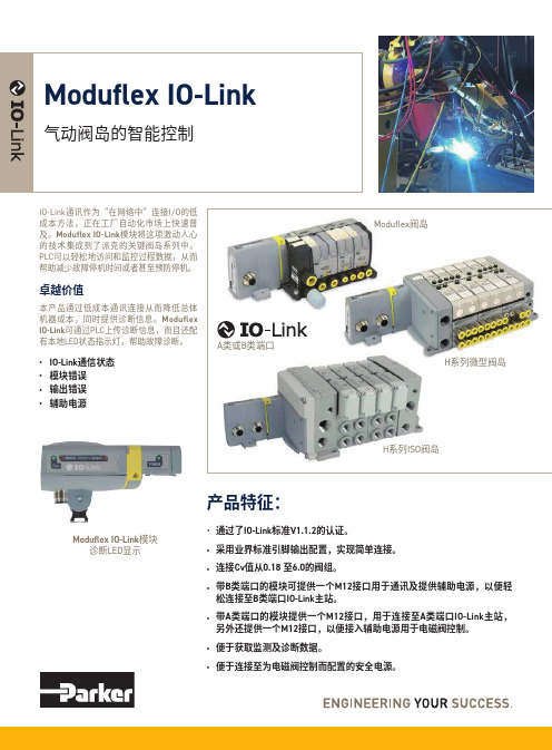
IO-Link端口类别 A类
IO-Link 3针 3针 3针
辅助电源 3针 3针 5针
辅助电源针脚定义 重量(g)
订货号
1&3
160 P2M2HBVL12400A13
4&3
160 P2M2HBVL12400A43
4&2
160 P2M2HBVL12400A42
๑使ᆩ用IO-IOL-iLniknᆩk用ᇀ于ݥ非ྪ网ஏ络ॐ架ࠓ构I/IO/੦O控制
Փ⫼使ᏺ用䲚带៤集I成O-ILOin- LkiЏn kキ主站ഫ模ⱘ块P的LCPˈL C⫼,Ѣ用I/于O᭄ ᇥI/Oⱘ数ᴎ更఼少的机器
* I/*OI-/LOi-nLkin㒓k 线㓚缆ⱘ的᳔最大䭓长ᑺ度202m0m * ߽* ⫼利I用O-ILOi-nLkin䖲k连接控ࠊ制᠔所᳝有ᴀ本ഄ地ⱘ的
卓越价值
本产品通过低成本通讯连接从而降低总体 机器成本,同时提供诊断信息。Moduflex IO-Link可通过PLC上传诊断信息,而且还配 有本地LED状态指示灯,帮助故障诊断。
• IO-Link通信状态 • 模块错误 • 输出错误 • 辅助电源
A类或B类端口
Moduflex阀岛 H系列微型阀岛
H系列ISO阀岛
© 2017 派克汉尼汾公司版权所有。保留所有权利。
H ISO 15407-2 Cv: 0.55 - 1.1 最多可带24个线圈 42mA/线圈
H ISO 5599-2 Cv: 1.5 - 6.0 最多可带24个线圈 133mA/线圈
23-06-A PNEU-CH-4P-IOLINK
B类
5针
2&5
140 P2M2HBVL12400B25
Parker负载敏感阀培训(L90LS)

50
100
200
50 200 56 6 BAR 210 210 106 6 BAR
100 206 6 BAR 210
200
210
THREE FUNCTION WITH INDIVIDUAL PRESSURE COMPENSATORS
Mobile Controls Division
30/03/2012
30/03/2012
Mobile Controls Division
K170LS/K220LS /K220LS
LS-systems Flow/section 170 l/min, without compensator 210 l/min Nodular iron Max pressure 320 bar Stackable 1 to 10 sections Motorports
compensators Feed reducers Force control Fast acting leak tight port relief valves Counter pressure valve Built-in pilot pressure supply Wide range of function adapted spools Copied load signal Intermediate sections Mid-inlet
50
100
200
50 200 210
100
200
210
210
210
210
210
210
THREE FUNCTIONS WITHOUT INDIVIDUAL PRESSURE COMPENSATORS
Mobile Controls Division
阀门培训内容
阀门培训内容一、前言阀门是流体输送系统中的控制部件,具有截止、调节、导流、稳压、分流、溢流、泄压等功能。
阀门广泛应用于石油、化工、天然气、电力、冶金、食品、制药等行业。
为了提高阀门使用效率,保障生产安全,降低维护成本,本培训旨在使参训人员全面了解阀门的结构、原理、选型、安装、调试、维护及故障处理等方面的知识。
二、阀门基础知识1. 阀门分类阀门按照结构可分为截止阀、球阀、蝶阀、闸阀、截止止回阀、安全阀等;按照驱动方式可分为手动、电动、气动、液压等;按照连接方式可分为法兰连接、螺纹连接、焊接连接等。
2. 阀门结构及工作原理阀门主要由阀体、阀盖、阀杆、阀瓣、密封圈等组成。
阀门通过改变阀门通道的截面积,实现流体的截止、调节、导流等功能。
不同类型的阀门具有不同的工作原理,如截止阀通过升降阀瓣实现截止,球阀通过旋转球体实现截止,蝶阀通过旋转蝶板实现调节等。
3. 阀门材质及密封面材料阀门的材质和密封面材料对阀门的使用性能和寿命具有重要影响。
阀门材质包括铸铁、碳钢、不锈钢、合金钢等;密封面材料包括橡胶、聚四氟乙烯、金属等。
根据流体介质的性质,选择合适的阀门材质和密封面材料。
三、阀门选型与安装1. 阀门选型(1)满足生产工艺要求;(2)保证流体介质安全、清洁、无泄漏;(3)操作简便,维护方便;(4)经济合理,降低成本。
2. 阀门安装(1)阀门安装方向应正确;(2)阀门与管道连接应牢固、严密;(3)阀门安装位置应便于操作、检修;(4)阀门安装高度应符合设计要求。
四、阀门调试与维护1. 阀门调试阀门调试主要包括手动操作、电动操作、气动操作等。
调试过程中,应检查阀门启闭是否灵活、密封是否严密、驱动装置是否正常。
对于特殊阀门,如安全阀、减压阀等,还需进行功能调试。
2. 阀门维护阀门维护主要包括日常检查、定期保养、故障排除等。
日常检查应关注阀门密封性能、驱动装置、连接部位等;定期保养应进行阀门清洗、润滑、更换密封圈等;故障排除应遵循先分析原因,后采取相应措施的原则。
阀门培训手册

阀门培训手册一、引言阀门是流体输送系统中的关键控制元件,广泛应用于石油、化工、电力、冶金、轻工、食品等行业。
为了确保阀门的正常运行,提高设备的安全性和经济效益,特制定本阀门培训手册。
本手册旨在为从事阀门安装、调试、维护和管理的工程技术人员提供系统的培训资料,帮助大家掌握阀门的基础知识和操作技能。
二、阀门基础知识1. 阀门分类阀门根据结构特点、工作原理和用途可分为多种类型,如截止阀、球阀、闸阀、蝶阀、截止止回阀、调节阀等。
不同类型的阀门具有不同的性能特点和适用范围。
2. 阀门结构阀门主要由阀体、阀盖、阀杆、阀瓣、密封圈等部件组成。
阀体和阀盖承受介质压力,阀杆连接执行机构和阀瓣,阀瓣用于截断或调节介质流量,密封圈保证阀门的密封性能。
3. 阀门参数阀门的主要参数包括公称直径、公称压力、适用温度、适用介质等。
公称直径是指阀门连接管道的尺寸,公称压力是指阀门能承受的最大压力。
选择阀门时,需根据实际工况确定合适的参数。
4. 阀门材质阀门的材质直接影响阀门的使用寿命和性能。
根据适用介质和工况条件,阀门材质可分为铸铁、碳钢、不锈钢、合金钢等。
特殊工况下,还可选用非金属材质(如塑料、陶瓷等)。
三、阀门安装与调试1. 安装前的准备(1)检查阀门型号、规格是否符合设计要求;(2)检查阀门及其附件是否完好,密封圈是否损坏;(3)确保安装现场环境清洁,避免阀门受到污染;(4)准备必要的安装工具和设备。
2. 安装步骤(1)将阀门安装在管道上,确保阀门与管道同轴;(2)按照设计要求连接阀门执行机构(如电动装置、气动装置等);(3)检查法兰连接处的密封垫片,确保无破损、老化等现象;(4)紧固螺栓,使法兰连接紧密。
3. 调试步骤(1)检查阀门执行机构是否正常,如电动装置的电源、气动装置的气源等;(2)操作阀门,观察阀门启闭是否灵活,有无卡阻现象;(3)检查阀门密封性能,观察有无泄漏;(4)根据实际工况,调整阀门的开度,满足系统要求。
Parker软管培训资料-派克液压胶管培训资料-技术培训资料

液压胶管结构与原理
结构
派克液压胶管由内胶层、增强层和外胶层组成,内胶层直接与液压油接触, 增强层用于提高胶管的耐压强度,外胶层则起保护和防腐作用。
工作原理
派克液压胶管在液压设备中作为传输液压油的介质,当液压油在胶管内流动 时,会产生一定的压力,从而实现动力或控制功能。
液压胶管性能参数
压力等级
派克液压胶管的压力等级是按照其耐压能力进行 分类的,一般分为低压、中压、高压和超高压四 个等级,不同等级的胶管适用于不同的液压设备 。
1
Hose Reels:包括手动和电动卷盘,以及固定 式和移动式卷盘
2
Quick Connect Couplings:包括直通、直角 、T型、L型等连接方式
3
Hose Assemblies:根据不同的应用需求,提 供多种胶管总成和附件
Parker软管技术参数
材料
采用高强度合成橡胶,具有优良的 抗老化性能和耐油性能
02
Parker液压胶管介绍
液压胶管种类与用途
根据用途分类
派克液压胶管广泛应用于各种液压设备中,如挖掘机、起重 机、推土机等,作为动力元件、控制元件和执行元件的液压 回路中的软管。
根据材质分类
派克液压胶管按材质可分为橡胶软管、橡塑复合管和聚氨酯 软管等,不同材质的软管具有不同的特性,如耐高温、耐油 、耐腐蚀等。
安全防护措施
为了防止液压系统的泄漏和污染 环境,应采取安全防护措施,如 设置泄漏收集槽、安装环保设施 等,确保设备和环境的可持续发 展。
05
Parker液压产品与服务
Parker液压产品种类及用途
01
Parker液压产品种类丰富,包括齿轮泵、柱塞泵、叶片泵、马 达等,适用于各种不同应用场景。
美国派克parker恒压泵负载敏感泵恒功率泵对比分析
10 GPM * 3000 PSI / 1714 = 17.5 HP
How much horsepower is being wasted ?
5 GPM * 3000 PSI / 1714 = 8.7 HP
5 GPM * 1000 PSI / 1714 = 2.9 HP
Total
= 11.6 HP
(assume 100 % efficiency)
10 GPM Fixed Pump Relief Valve Set at 3000 PSI Flow Control Set for 5 GPM
Load Pressure is 2000 PSI
What is the horsepower being consumed while the cylinder is extending ?
Hydraulic Pump/Motor Division
Hydraulic Piston Pump Basics
Hydraulic Pump/Motor Division
Hydraulic Pump Basics
Hydraulic Flow is developed as the pump rotating group is driven by a prime mover
• Variable Displacement
– Good for variable flow and / or pressure applications – Typically more energy efficient because flow and
pressure ( Horsepower) more closely matches load.
Parker软管培训资料-派克液压胶管培训资料-技术培训资料

02
液压胶管连接
应正确连接接头,避免渗漏或空气进 入液压系统。
03
液压胶管清洁
保持管道清洁,防止灰尘和杂质进入 液压系统。
液压胶管故障排除与预防
液压胶管漏油
如出现漏油,应检查管道和接头是否受损,如有问题及时更换。
液压胶管噪音
如出现噪音,应检查液压胶管是否太紧或老化,如有问题及时更 换。
2023
《parker软管培训资料-派 克液压胶管培训资料-技术
培训资料》
目录
• Parker软管介绍 • Parker液压胶管介绍 • Parker液压胶管技术培训 • Parker液压胶管应用案例 • Parker液压胶管与其他产品的比较 • Parker液压胶管市场前景与展望
01
Parker软管介绍
环保与节能趋势
在环保和节能方面,液压胶管也面临着新的挑战和机遇 ,如发展耐高温、耐高压、低流阻的液压胶管,减少能 源消耗和降低环境污染。
Parker液压胶管在市场中的地位
市场领导者
作为液压胶管领域的知名品牌,Parker在市场中具有极高的知名 度和影响力,是液压胶管市场的领导者之一。
技术创新者
Parker在液压胶管领域一直致力于技术创新和产品升级,推出了 一系列高品质的液压胶管产品,引领行业发展。
03
Parker液压胶管技术培训
液压胶管安装与维护
液压胶管储存
应储存于干燥、无尘和温度稳定的地方,避免阳 光直射。
液压胶管安装
安装前应检查管道是否有损伤,安装时应使用正 确的工具,避免强力扭曲或弯曲。
液压胶管维护
定期检查软管是否出现磨损、裂纹或老化,及时 更换。
Parker Hannifin 加油门控阀值系列商品说明说明书
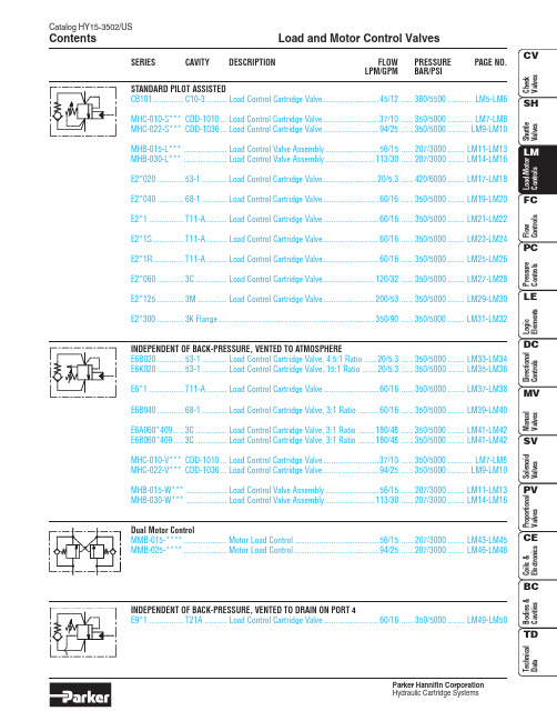
Load and Motor Control ValvesParker Hannifin CorporationContentsSERIESCAVITYDESCRIPTIONFLOW PRESSURE PAGE NO.LPM/GPMBAR/PSISTANDARD PILOT ASSISTEDCB101...............C10-3..........Load Control Cartridge Valve...........................45/12......380/5500............LM5-LM6MHC-010-S***CDD-1010...Load Control Cartridge Valve...........................37/10......350/5000............LM7-LM8MHC-022-S***CDD-1036...Load Control Cartridge Valve...........................94/25......350/5000..........LM9-LM10MHB-015-L***.....................Load Control Valve Assembly..........................56/15......207/3000........LM11-LM13MHB-030-L***.....................Load Control Valve Assembly........................113/30......207/3000........LM14-LM16E2*020.............53-1............Load Control Cartridge Valve..........................20/5.3......420/6000........LM17-LM18E2*040.............68-1............Load Control Cartridge Valve...........................60/16......350/5000........LM19-LM20E2*1.................T11-A..........Load Control Cartridge Valve...........................60/16......350/5000........LM21-LM22E2*1S...............T11-A..........Load Control Cartridge Valve...........................60/16......350/5000........LM23-LM24E2*1R...............T11-A..........Load Control Cartridge Valve...........................60/16......350/5000........LM25-LM26E2*060.............3C ...............Load Control Cartridge Valve.........................120/32......350/5000........LM27-LM28E2*125.............3M ..............Load Control Cartridge Valve.........................200/53......350/5000........LM29-LM30E2*300.............3K Flange............................................................................350/90......350/5000........LM31-LM32INDEPENDENT OF BACK-PRESSURE, VENTED TO DRAIN ON PORT 4E9*1.................T21A ...........Load Control Cartridge Valve...........................60/16......350/5000........LM49-LM50LM1Load and Motor Control ValvesTechnical TipsParker Hannifin CorporationLoad and Motor Control Valves Technical TipsParker Hannifin CorporationCB101be greater than the bias spring plus the tank pressure before the counterbalance poppet will shift allowing flow.A vented style counterbalance valve relieves the biasspring chamber to atmosphere. Thus, the springchamber is in no way related to the tank chamber ofthe counterbalance valve. So, if the pressure on the tank line is high, or if the pressure setting is critical, then avented style counterbalance valve would be required.E6B060LM2LM3Load and Motor Control ValvesTechnical TipsParker Hannifin CorporationSelection Options (Continued)Pilot Ratio – The pilot ratio is the ratio of the pilot area versus the differential area poppet. Thus, the higher the pilot ratio, the less pressure that is needed toassist the load pressure in unseating the poppet. This means there is less restriction to the overrunning load,resulting in less horsepower required and more control of the load. So higher pilot ratio equates to less restriction to the overrunning load, less control and less horsepower required. Lower ratio equates to more restriction to the overrunning load, more control and more horse-power required.The pilot ratiodecision is one of Horsepower versus Control. Forreference the most popular ratio is 6:1.ADJUSTMENT TYPEParker offers counterbalance valves with adjustable and non-adjustable pressure settings. The non-adjustable or shimmed version is recommended for most applications as it prevents tampering or improper adjustment by uneducated end users.SELECTING SETTINGSThere are three basic settings to consider before finalizing a counterbalance valve for your application.Holding Setting – The holding setting is sometimes referred to as the counterbalance setting. It is the maximum load setting you expect the counterbalance to hold. Note that the counterbalance valve should be set for the absolute maximum hold pressure required.Also note that counterbalance valves are restrictive type devices and as such are not ideal for low pres-sure applications, such as those below 750 psi. The holding setting is the setting you choose when select-ing a counterbalance valve.P P = (T S – L) / R PP P = Pilot Pressure T S = Thermal Setting L = Induced Load R P= Pilot RatioExample:The maximum load is 3000 psi. A 6:1 Pilot Ratio was chosen and the thermal relief setting is the standard 1000 psi over load setting. What is the pilot pressure required to retract the cylinder if it is fully loaded? What pilot pressure is required to retract the cylinder if there is no load?FULL Y LOADED:P P = (4000 psi – 3000 psi) / 6P P = 1000 psi / 6P P = 167 psiThus, any time the pilot line sees at least 167 psi, the cylinder could lower the load.UNLOADED:P P = (4000 psi – 0 psi) / 6P P = 4000 psi / 6P P = 667 psiThus, at least 667 psi will be needed to lower the cylinder when it is unloaded.Sample Ratios:10:1Primary function is load holding or hose break protectionLoads moving at fast speeds and positioning is not critical7:1, 6:1 and 5:1Most popular starting ratio 4:1 and 3:1Positioning is critical such as a pick and place applicationInstability with 6:1 ratio 1:1Motor control applicationThermal Setting – Counterbalance valves have a built-in thermal relief valve that compensates for the expansion of oil, due to temperature, by bleeding off excess pressure. In other words, the thermal setting is the pressure that the counterbalance will unload at if no pressure is present at the pilot port. Obviously, this setting should be above the holding setting. The Parker MHC counterbalance valves are automatically set1000 psi above the holding setting of the valve. You do not specify this setting, only the holding setting.For the CB101 Series, you do specify the Thermal/Crack setting in the model code. The holding setting (maximum load induced pressure) is 70% of that specified setting. Example: Hold at 3000 psi, crack at 4285 psi. For the E2 Series, you specify the Thermal/Crack setting in the model code. The crack setting(maximum load induced pressure) should be 1.3 times the hold. Example: Hold at 3000 psi, crack at 3900 psi.Pilot Area – The pilot pressure required to lower the cylinder when fully loaded and unloaded can also be determined before applying the valve. The pilot pres-sure can be determined by the below equation:LessMorePilot Ratio 4:110:11:16:1Control HP Required NO LOADLOADLoad and Motor Control Valves Technical TipsParker Hannifin CorporationLM4。
Parker Pneumatic N Series 气动阀门说明书
Material specificationsValve body Cast aluminumPoppet assembly Aluminum and stainless steel Pilot Valve Zinc, stainless steel, brass,copper, zinc plated steel SealsNitrileFeatures• Continuous duty rated option • Non-lube service• Hi-flow, short stroke poppet • Indicator lights available Specifications • 2-way NC• 3-way NO & NC • Selector functionPorts• 3/8" Body – 3/8", 1/2" NPT • 3/4" Body – 1/2", 3/4", 1" NPT• 1-1/4" Body – 1", 1-1/4", 1-1/2" NPT • BSPP “G” threads availableCertification / approval• Approved to be CE marked (Standard L-Pilot & P-Pilot)• NEMA 4 Option• Hazardous Duty Option IP 65 Rating / NEMA 4LubricationThe high speed poppet valves are pre-lubricated to permit use with non-lubricated air. However, air should be lubricated to assure maximum seal life.F442 lubricating oil is recommended. This oil is speciallyformulated to provide peak performance and maximum service life from air-operated equipment.InstallationCAUTION: DO NOT RESTRICT THE INLET TO POPPET VALVESRestriction of the inlet can starve the air supply to the pilot section of internally piloted poppet valves and result in slow shifting or failure of the valve to shift properly. Always connect the supply line directly to the inlet of the valve using the full pipe size of the valve inlet. Never use a quick coupling to connect a poppet valve to the air supply. On valves with a small inlet port, use of an upstream surge tank may be required at lower operating pressures to insure an adequate air supply and proper operation.Single Solenoid, Locking manual override, internal “P” pilot 140 PSI, standard service, junction box w/ light.Body In / cyl Exhaust 2-way, 2-position 3-way, 2-position 3-way, 2-positionSingle Remote Pilot, 1/4" NPT remote pilot port with internal pilot return.Body In / cyl Exhaust 2-way, 2-position 3-way, 2-position 3-way, 2-positionSingle Solenoid, Locking manual override, internal “P” pilot 125 PSI, standard service, P-pilot junction box w/ light.Body In / cyl Exhaust 2-way, 2-position 3-way, 2-position 3-way, 2-positionSingle Remote Pilot, 1/4" NPT remote pilot port with internal pilot return.Body In / cyl Exhaust 2-way, 2-position 3-way, 2-position 3-way, 2-positionParker PneumaticN Series Valves Model Number Index“N” Series 3/8", 3/4" & 1-1/4" Body Sizes - Solenoid ‘L’ PilotNote: BSPP is to the ISO 228 standard, and requires an R-BSPT male fitting.“N” Series 1-1/4" Body Sizes - Solenoid Hi-Flow ‘P’ PilotR-BSPT male fitting.Parker PneumaticReplacement PilotsDescriptionHazardous duty L-pilot NEMA 4 L-pilot Hazardous duty L-pilot - UL & CSA K0451025**N/AOverride typeLocking Non-Locking Locking Non-Locking Hazardous duty with override K0453025**K0452025**NEMA 4 with overrideK2553025**K255202549** Voltage code - 49 & 53N Series Valve Replacement PartsReplacement PilotsDescription Standard L-pilot Continuous duty L-pilot Override type Locking Non-locking Locking Non-locking Basic with overrideK0653035**K0652035**K0853025**K0852025**JIC with junction box & override K0656035**K0655035**K0856025**K0855025**JIC pilot with junction box &override & indicator lights (120VAC only)K0659035**K0658035**K0859025**K0858025**** Voltage code - (reference model index for availability)Replacement PilotsDescription Heavy duty P-Pilot Override type No override Non-locking Locking Basic with overrideK1351045**N/A N/AJIC with junction box & override N/A K1355045**K1356045**JIC Pilot with junction box & override & indicator lights (120VAC only)N/AK135804553K135904553** Voltage code - 49 & 53Voltage Code **Voltage Coil 60Hz 50Hz DC 19" Leads 72" Leads 4224——K593099—43—24—K593098—45——12K593094—49—— 24K593097—51——48—K59325453115——K593108—58—230—K593111—Coils for L-Pilot Operated ValvesCoils for P-Pilot Operated ValvesVoltage Code **Voltage Coil60Hz 50Hz DC 19" Leads 72" Leads 4012——K593007—41,4224—6K593003—45*——12K593010—49*——24 (Standard)K593014—79——24 (ArcSuppressed)K593271—51*——48—K59318553*120110—K593025—57*240240—K593035—60240220—K593035—61——120K593041—* Indicates voltages approved for solenoid operators designed for use inhazardous locations.NVoltage Code* *Internal Pilot -3/8" & 3/4" Basic BodyKey 3/8" Body3/4" Body Inch mm Inch mm A 1.5640 2.1354B 1.5038 1.9449C1.8146 1.3434D .5614.5614E 3/8-16UNC 7/16" deep 3/8-16UNC 9/16" deepF 1.7544 2.2557G 1.5038 1.5038H 5.921507.14181J3.1981 3.7595K 1.8847 2.4462N 1.4437 1.7845P 7.361968.58218Q2.31593.0984216891351051A 10AKey 3/8" Valve 3/4" Valve Description4*H14510H13676U-cup (3/8), o-ring (3/4)5K493002K493009Stem6K202001K202002Lower piston assy.7*H14509H13676U-cup (3/8), o-ring (3/4)8H17811H17813Washer (2)9H06326H06332Stop nut (2)10K103035K103053Bottom cap (N.C.)10A K092020K092034Bottom cap assy. (N.O.)11*K183049K183057Gasket 12K473014K473015Spring 13K563015K563017Adapter 14*K41RB72121K41RB72221O-ringKey3/8" Valve 3/4" Valve Description1—1/2" Tap K053075Body (N.C.)3/8" TapK0530223/4" Tap K0530761/2" Tap K0530231" Tap K0532201A—3/4" Tap K053077Body (N.O.)3/8" Tap K0530253/4" Tap K0530781/2" Tap K0530261" Tap K0532182K212001K212002Upper piston assy Top view indicates flow through 3-Way valve with coil de-energized.NOTE: For normal valve operation, override must be in “out” position.Service KitsInclude all parts normally required for in-service maintenance:3/8" Basic valve with standard service L -Pilots .................K352076 3/8" Basic valve with continuous duty L -Pilots .....................K3522763/4" Basic valve with standard service L -Pilots .................K3520773/4" Basic valve with continuous duty L -Pilots .....................K352277Exhaust PressureNormally Closed1351A 10A216891351410Key 3/8" Valve 3/4" Valve Description 4*K41RB72211H13676O-ring 5K493002K493009Stem6K202001K202002Lower piston assy.7*K41RB72210H13676O-ring 8H17811H17813Washer (2)9H06326H06332Stop nut (2)10K103035K103053Bottom cap (N.C.)10A K092020K092034Bottom cap assy. (N.O.)11K473014K473015Spring 12*K183049K183057Gasket 13K563016K563021Adapter 14*K41RB72121K41RB72221O-ringKey 3/8" Valve 3/4" Valve Description1—1/2" Tap K053067Body (N.C.)3/8" TapK0530193/4" Tap K0530691/2" Tap K0531571" Tap K0532211A—3/4" Tap K053065Body (N.O.)3/8" Tap K0530183/4" Tap K0530701/2" Tap K0530641" Tap K0532192K212001K212002Upper piston assy 3*H13648H13728SealNormally ClosedNormally OpenExternal Pilot -3/8" & 3/4" Basic BodyKey 3/8" Body 3/4" Body Inch mm Inch mm A 1.5640 2.1354B 1.5038 1.9449C1.8146 1.3434D .5614.5614E3/8-16UNC 7/16" deep 3/8-16UNC 9/16" deepF 1.7544 2.2557G 1.5038 1.5038H 6.421637.45189J 3.1981 3.7595K 1.8847 2.4462N1.4437 1.7845P 7.862008.89226Q2.31593.0984R4.341105.38137Top view indicates flow through 3-Way valve with coil de-energized.NOTE: For normal valve operation, override must be in “out” position.Service KitsInclude all parts normally required for in-service maintenance:3/8" Basic valve with standard service L -Pilots .................K3520763/8" Basic valve with continuous duty L -Pilots .....................K3522763/4" Basic valve with standard service L -Pilots .................K3520773/4" Basic valve with continuous duty L -Pilots .....................K352277Exhaust PressureTop view indicates flow through 3-Way valve with coil de-energized.NOTE: For normal valve operation, override must be in “out” position.Service KitsInclude all parts normally required for in-service maintenance:1-1/4" Basic valve with standard service P-Pilots ............K352078Exhaust Pressure5Key 1-1/4" Valve Description 4*H13728Seal 5K493016Stem6K313028Lower piston 7*H13728Seal 8H17817Washer 9H06338Stop nut10K092046Bottom cap (N.C.)10A K103061Bottom cap (N.O.)11*K183058Gasket 12K473016Spring 13K012003Adapter 14*K41RB72143O-ringKey1-1/4" Valve Description11" Tap K053111Body (N.C.)1-1/4" Tap K0531121-1/2" Tap K0531131A1" Tap K053114Body (N.O.)1-1/4" Tap K0531151-1/2" Tap K0531162K313029Upper piston assy 3*H13752O-ringInternal Pilot - 1-1/4" Basic BodyInternal Pilot - 1-1/4" Basic BodyKey 1-14" BodyInch mm A 3.0076B2.2557C 1.3434D 1.1930E 1/2-13 UNC 3/4 DeepF 3.1380G 1.5038H 9.30236J5.34136K 3.4487N2.3159P 11.14283Q4.56116Continuous Duty Pilot - 1-1/4" Basic BodyContinuous Duty Pilot - 1-1/4" Basic BodyKey 1-1/4" BodyInch mm A 3.0076B 2.2557C1.3434D 1.1930E 1/2-13 UNC 3/4 DeepF 3.1380G 1.5038H 9.02229J 5.34136K 3.4487N2.3159P 10.45265Q4.561165Key 1-1/4" Valve Description 4*H13728Seal 5K493016Stem6K313028Lower piston 7*H13728Seal 8H17817Washer 9H06338Stop nut10K092046Bottom cap (N.C.)10A K103061Bottom cap (N.O.)11*K183058Gasket 12K473016Spring 13K012003Adapter 14*K41RB72143O-ringKey1-1/4" Valve Description11" Tap K053111Body (N.C.)1-1/4" Tap K0531121-1/2" Tap K0531131A1" Tap K053114Body (N.O.)1-1/4" Tap K0531151-1/2" Tap K0531162K313029Upper piston assy Normally ClosedTop view indicates flow through 3-Way valve with coil de-energized.NOTE: For normal valve operation, override must be in “out” position.Service KitsInclude all parts normally required for in-service maintenance:1-1/4" Basic valve with continuous duty L -Pilot ...................K352080Exhaust PressureInternal Return - 3/8", 3/4", 1-1/4" Basic BodyKey3/8" Body 3/4" Body 1-1/4" Body Inch mm Inch mm Inch mmH 3.1981 3.7595 5.34136J 1.8848 2.4462 3.4487M 1.4437 1.7845 2.6667N 4.22107 5.311357.19183Q2.31593.09784.56116Key 3/8" Valve 3/4" Valve1-1/4" Valve Description 5K493002K493009K493016Stem6K202001K202002K313028Lower pistonassy.7*H13499H13676H13728Seal 8H17811H17813H17817Washer (2)9H06326H06332H06338Stop nut (2)10K092020K092034K092046Bottom cap(N.C.)10A K103035K103053K103061Bottom cap(N.O.)11*K183049K183057K183058Gasket 12K473014K473015K473016Spring 14*K41RB72121K41RB72221K41RB72143O-ring 21K123018K123021K123024CoverKey 3/8" Valve 3/4" Valve1-1/4" ValveDescription1—1/2" TapK0530751" Tap K053111Body (N.O.)3/8" Tap K0530223/4" Tap K0530761-1/4" Tap K0531121/2" Tap K0530231" Tap K0532201-1/2" Tap K0531131A—1/2" TapK0530771" Tap K053114Body (N.C.)3/8" Tap K0530253/4" Tap K0530781-1/4" Tap K0531151/2" Tap K0530261" Tap K0532181-1/2" Tap K0531162K212001K212002K313029Upper piston assy 3*H13648H13728H13752Seal 4*H14510H13676H13728Seal2152151A 7*10Service KitsInclude all parts normally required for in-service maintenance:3/8" Basic valve ........................K3520733/4" Basic valve .........................K3520741-1/4" Basic valve .....................K352075Normally ClosedTop view indicates flow through 3-Way valve.NOTE: For normal valve operation, override must be in “out” position.Exhaust PressureTop view indicates flow through 3-Way valve.NOTE: For normal valve operation, override must be in “out” position.Exhaust Pressure132151051A 7*Internal Return - 3/8", 3/4", 1-1/4" Basic BodyKey 3/8" Body 3/4" Body 1-1/4" Body Inch mm Inch mm Inch mm A 1.5640 2.1354 3.0076B 1.5038 1.9449 2.2557C 1.1329 1.1329 2.3860D .5614.5614 1.1930E 3/8–16UNC 7/16" deep 3/8– 16UNC 9/16" deep 1/2–13UNC 3/4" deep F 1.7544 2.2557 3.1379G 1.5640 2.1354 3.1379H 3.1981 3.7595 5.34136J 1.8848 2.4462 3.4487K 2.3159 3.0978 4.56116L 4.34110 5.381377.31186M5.311356.341617.88200N Left of centerOn center.53 13 1.0025Q1.4437 1.78452.3159Key 3/8" Valve 3/4" Valve1-1/4" Valve Description 5K493002K493009K493016Stem6K202001K202002K313028Lower pistonassy.7*H13499H13676H13728Seal 8H17811H17813H17817Washer (2)9H06326H06332H06338Stop nut (2)10K092020K092034K092046Bottom capassy. (N.C.)10A K103035K103053K103061Bottom cap(N.O.)11*K183049K183057K183058Gasket 12K473014K473015K473016Spring 13K563016K563021K563027Adapter 14*K41RB72121K41RB72221K41RB72143O-ring 21K323027K323027Not used CoverKey3/8" Valve 3/4" Valve 1-1/4" Valve Description11/4" Tap K0530111/2" Tap K0530671" Tap K053143Body (N.O.)—3/4" Tap K0530691-1/4" Tap K0531101/2" TapK0531571" Tap K0532211-1/2" Tap K0531461A 1/4" Tap K0530101/2" Tap K0530651" Tap K053159Body (N.C.)—3/4" Tap K0530701-1/4" Tap K0531441/2" Tap K0530641" Tap K053 2191-1/2" Tap K0531452K212001K212002K313029Upper piston assy 3*H13648H13728H13752Seal 4*H13529H13676H13728SealNormally ClosedService KitsInclude all parts normally required for in-service maintenance:3/8" Basic valve ........................K3520313/4" Basic valve ........................K3520561-1/4" Basic valve .....................K352083Catalog PDN1000-2USParker PneumaticParker Hannifin Corporation Pneumatic Division Richland, Michigan/pneumaticsD66Valve ProductsN Series Valve DimensionsInternal Return -3/8" & 3/4" Basic BodyKey 3/8" Body 3/4" Body 1-1/4" Body Inch mm Inch mm Inch mm A 1.5640 2.1354 3.0076B 1.5038 1.9449 2.2557C 1.1329 1.1329 2.3860D .5614.5614 1.1930E 3/8–16UNC 7/16" deep 3/8–16UNC 9/16" deep 1/2–13UNC 3/4" deep F 1.7544 2.2557 3.1379G 1.5640 2.1354 3.1379H 3.1981 3.7595 5.34136J 1.8848 2.4462 3.4487K .5013.5013.5013L .113.164.256M 1.4437 1.7845 2.6667N 4.22107 5.311357.19183P 4.78121 5.561417.53191Q2.31593.09784.56116Internal Return -3/8" & 3/4" Basic Body3/8" Body 3/4" Body 1-1/4" Body Key Inch mm Inch mm Inch mm A 1.5640 2.1354 3.0076B 1.5038 1.9449 2.2557C 1.1329 1.1329 2.3860D .5614.5614 1.1930E3/8–16UNC 7/16" deep 3/8–16UNC 9/16" deep 1/2–13UNC 3/4" deep F 1.7544 2.2557 3.1379G 1.5640 2.1354 3.1379H 3.1981 3.7595 5.34136J 1.8848 2.4462 3.4487K 2.3159 3.0978 4.56116L 4.34110 5.381377.31186M 5.31135 6.341617.88200N Left of centerOn center.53 13 1.0025Q1.44371.78452.3159Internal Return - 3/8" & 3/4" Basic BodyExternal Return - 3/8" & 3/4" Basic Body1/4 NPT 。
Parker Hannifin 加力系统控制阀门指南说明书

Catalog HY15-3502/USLM35Load Control Valve Series E6K020Parker Hannifin CorporationHydraulic Cartridge SystemsGeneral DescriptionThreaded Cartridge Style Counterbalance Valve.Pilot assisted, designed for motion control applications. For additional information see Technical Tips on pages LM1-LM4.Features•Spring chamber isolated from system backpressure by double seal, eliminating vent port leakage and need for separate drain line•Poppet construction for minimal leakage•Suitable for remote pilot controlled boomlock applications as per ISO8463•Incorporates direct acting relief valve for overload protection•Includes reverse check valve within body•Hardened working parts for maximum durability •Adjustable and tamper resistant versions available •All external parts zinc platedSpecificationsTechnical InformationPerformance CurvesRated Flow 20 LPM (5.3 GPM)Pressure 100 - 350 Bar (1450 - 5075 PSI)Sensitivity:114 Bar (1650 PSI)Pressure/Turn Pilot Ratio 15 : 1Cartridge Material All parts steel. All operating parts hardened steel.Operating Temp.-40°C to +93.3°C (Nitrile)Range/Seals(-40°F to +200°F)-31.7°C to +121.1°C (Fluorocarbon)(-25°F to +250°F)FluidMineral-based or synthetic with Compatibility/lubricating properties at viscosities Viscosity of 45 to 2000 SSU (6 to 420 cSt)Filtration ISO Code 16/13,SAE Class 4 or better Approx. Weight 0.08 kg (0.18 lbs.)Cavity53-1(See BC Section for more details)Flow (Q)102.651.3GPM154.0205.3Hydraulic Oil 150 SSU @ 100°F (32 cSt)P r e s su r e D r o p B a r ,P S IRelief & Pilot Performance 1 to 2Flow (Q)102.651.3GPM154.0205.3Pressure Drop vs FlowHydraulic Oil 150 SSU @ 100°F (32 cSt)73290PSI 145218P r e s s u r D r o p B a r ,P S I(1)(2)Load Control Valve Series E6K020Catalog HY15-3502/USLM36Parker Hannifin CorporationHydraulic Cartridge SystemsTechnical Information DimensionsMillimeters (Inches)Ordering InformationAdjustment StyleCrackingPressureSealsCode Seals / Kit No.N Nitrile, Buna-N (Std.) /(SK30087N-1)VFluorocarbon /(SK30087V-1)Code Pilot Ratio K 15 : 1E6Pilot RatioLoad Control Valve*Standard valve is set to crack at 215 Bar (3120 PSI). Valve to be set to 1.3 times maximum load induced pressure.Code Body Material A Aluminum SSteelCode Porting3103/8″ BSP (main) 1/4″ BSP (aux)3183/8″ SAE (main) 1/4″ SAE (aux)3123/8″ BSP Dual Cavity 3193/8″ SAE Dual Cavity Code Adjustment Style / Kit No.Z Screw Adjust (Standard)TTamper Resistant (TC1125)020Code Cracking PressureOmit for no setting (Standard)*Specify setting if requiredBody MaterialPortingLine BodyLB10Order Bodies SeparatelyK。
阀门培训大纲
第一章阀门基础知识1.1型号编制说明1.2执行器及选型1.3材料1.4法兰标准及配套附件说明1.5阀门选型、温度—压力对照参数表第二章公司供货产品介绍第三章临氢阀门-美国克雷恩公司NACE阀门选用对照第一章阀门基础知识一、阀门基本知识、阀类:1—表示阀类 Z(闸阀) J(截止阀)L(节流阀) H(止回阀)D(蝶阀)G(隔膜阀)Q(球阀) T(调节阀)S(疏水阀)X(旋塞阀)公司特有型号:NK NS NH NC2—表示操作方式: 3(蜗轮) 4(正齿轮) 5(伞齿轮) 6(气动) 7(液动)8(电-液联动) 9(电动)无(手动)如:Z540H- Q661F- D741H D341X3—连接方式 1(内螺纹) 2(外螺纹)4(法兰)6(BW对焊,SW承插焊) 7(对夹)J11H J23H Q41F Z60Y D71X H76H4—结构形式闸阀 0--弹性闸板DN50以上、1--楔式单闸板 DN50以下、2--楔式双闸板、3--平行单闸板、4--平行双闸板如:Z40H Z41H Z42H Z44H—截止阀 1--T型 4--角式 5--Y型 6—J41H J44H J65Y J46H—止回阀 1--升降式、 2--立式、 4--旋启式、5--Y型 6--双瓣式 7—单瓣旋启式如;H41H H71H H44H H42H H65Y H76H H47H—蝶阀 1--中性弹性 2--二偏心 3--金属三偏心,如:D371X-10 D343H-10C—隔膜阀 1--T型、6--直通式,如:EG41J G41J G46J—球阀 1--浮动式、4、5--三通、7--固定如:Q41F Q41H Q45F Q347F4.7 公司特殊产品,NK--表示真空阀、NH--表示抽气止回阀、PK--表示真空破坏阀、NS--表示堵阀、同时详细看美标API闸阀样本规定的产品编制规定。
熟悉公司规定的产品,详见附表1:以上表为公司特殊型号4.8 其他阀门公司自行规定的产品编制方法,在平时接触时应该予以注意,尤其是中石化行业的API阀门有特殊规定的编制方法。
Parker Pneumatic Valve产品说明书
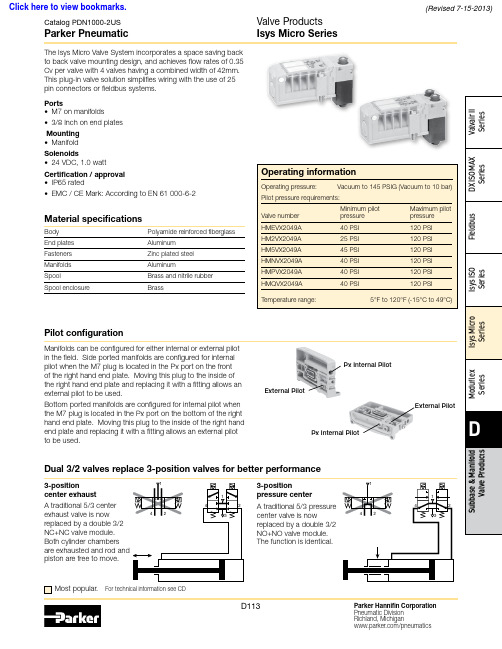
Material specificationsBody Polyamide reinforced fiberglass End plates Aluminum Fasteners Zinc plated steel Manifolds AluminumSpoolBrass and nitrile rubber Spool enclosureBrassMost popular.For technical information see CDThis plug-in valve solution simplifies wiring with the use of 25 pin connectors or fieldbus systems.Ports• M7 on manifolds• 3/8 Inch on end platesMounting • ManifoldSolenoids• 24 VDC, 1.0 wattCertification / approval • IP65 rated• EMC / CE Mark: According to EN 61 000-6-2Manifolds can be configured for either internal or external pilot in the field. Side ported manifolds are configured for internal pilot when the M7 plug is located in the Px port on the front of the right hand end plate. Moving this plug to the inside of the right hand end plate and replacing it with a fitting allows an external pilot to be used.Bottom ported manifolds are configured for internal pilot when the M7 plug is located in the Px port on the bottom of the right hand end plate. Moving this plug to the inside of the right hand end plate and replacing it with a fitting allows an external pilot to be used.External PilotPx Internal PilotPx Internal PilotExternal Pilot3-positioncenter exhaustA traditional 5/3 center exhaust valve is now replaced by a double 3/2 NC+NC valve module. Both cylinder chambers piston are free to move.Dual 3/2 valves replace 3-position valves for better performance3-positionpressure center A traditional 5/3 pressure center valve is nowreplaced by a double 3/2 NO+NO valve module. The function is identical.Pilot configurationPlug-in valve manifolds Part numbers Side port Bottom port Single solenoid outputs onlyPSM21JAPPSM22JAP Double or single solenoid outputsPSM21MAPPSM22MAPIsys Micro ValvesSymbolTypeCv Operator Part numberInternal Pilot End Plate KitsElectrical option Porting Side port Bottom portSimple Manifold Assemblies** Requires fitting “P”.BOLD OPTIONS ARE MOST POPULAR.N 7D 1516Valve Position A - Character 9Fitting Position A - Character 10Valve Position C - Character 13Fitting Position C - Character 14Valve Position B - Character 11Fitting Position B - Character 12Valve Position D - Character 15Fitting Position D - Character 16ACDACDBBIncludes a valve manifold with 4 valves and fittings installed. End Plates must be ordered separately.1. List Add-A-Fold Assembly call out. This automatically includes the end plate kit assembly.2. List Simple Manifold Assemblies. List left to right, LOOkING AT ThE CyLINDER PORTS on the manifold.Maximum Number of Solenoids(Maximum Energized Simultaneously)25-pinD-sub Moduflex Isysnet*Turck16Outputs32Outputs 24VDC24 (24)16 (16)32 (32)16 (16)32 (32) * Maximum of 32 solenoids per manifold. With Bus Extension functionality,4 manifolds with up to 32 solenoids each can be connected on the same network.Add-A-Fold Assembly Model NumberHow To Order Plug-in Add-A-Fold AssembliesNote:BSPP fittings can only be used with BSPP Manifolds.NPT fittings can only be used with NPT Manifolds.Sandwich RegulatorFlow Controls2-position and Dual 3/2 valves, and 0.17 for 3-position APB valves.Note: The sandwich regulator passes full pilot pressure from the manifold,allowing the regulated pressure to adjusted down to 5 PSI without affecting valve functionality.25-pin, D-Sub ManifoldsComponent LevelItem Qty Description Part number 01125-pin, D-sub, end plate PSML25AP0224Single solenoid valveHMEVX2049A 036Manifold, side ported, single address PSM21JAP 04501/4" Tube fittings (in box quantity)PS56792505103/8" Tube fittings (in box quantity)PS5683380613/8" Exhaust muffler P6M-PAB30711/8" Exhaust mufflerP6M-PAB1Add-A-FoldManifold is factory assembled and tested for pneumatic leaks and electrical continuity.Item Qty Description Part number 01124 valve Add-A-Fold with end platesAAHMD5249M0M 0264 valve simple manifold slices #1-6PSM31JAPE7E7E7E725-pin, D-Sub Cable (Female)DescriptionLengthPart number25-pin, D-sub cable, IP20 3 meters P8LMH25M3A 25-pin, D-sub cable, IP209 meters SCD259D 25-pin, D-sub cable, IP65 3 meters SCD253W 25-pin, D-sub cable, IP659 meters SCD259WE24 Single Solenoid ValvesManifold Slice #1Manifold Slice #2Manifold Slice #3Manifold Slice #5Manifold Slice #4Manifold Slice #6MufflersFittings – Must be ordered in multiples of 10ThreadTube O.D.Part numberPSM0001 –All ports open. Common pressure for front and rear mon exhausts.Standard gasket included with each manifold and end plate.Back Row OpenCommon Front Row OpenPSM0001PSM0001PSM0002 –Rear manifold blocked for separate pressure mon exhausts.Flip gasket to block front of manifold.Back Row Blocked Common Front Row OpenPSM0002PSM0002Intermediate* Qty. (2) PSM0002 Gaskets are required.Remainder are PSM0001 Gaskets (Not shown)Internal Pilot Pressure from P1 InletPSM0003 –Rear manifold blocked for separate pressure supply.Exhaust blocked also.Flip gasket to block front of manifold.If used with bottom ported end plates, second exhaust must be piped from the side of the right end plate.Back Row Blocked Common Front Row OpenIntermediatePSM0003PSM0003PSM0002PSM0002* Qty. (1) PSM0003 and Qty. (1) PSM0002 Gaskets are required.Remainder are PSM0001 Gaskets (Not shown)Internal Pilot Pressure from P1 Inlet PSM0004 –All galleys blocked.Two pressure zones and two exhaust zones.If used with bottom ported end plates, second exhaust must be piped from the side of the right end plate.PressurePressureExhaustExhaustBack Row Blocked Common Front Row BlockedIntermediate * Qty. (1) PSM0004 Gasket is required.Remainder are PSM0001 Gaskets (Not shown)PSM0004PSM0001PSM0004PSM0001Internal Pilot Pressure from P2 InletMultiple Pressure ZonesReplacement ScrewsManifold to Manifold Gaskets*Valve Labels*Replacement Solenoid Kit Replacement Override Caps Replacement Regulator GaugeReplacement Protective CoverReplacement Gaskets and Valve ScrewsReplacement PlugsDescription Part numberDimensionsA 4.88 (124.0)B 4.41 (112.0)C 2.95 (75.0)D 1.65 (42.0)E 1.22 (31.0)F 1.02 (26.0)G 0.71 (18.0)H 0.49 (12.5)J 2.28 (58.0)K 3.44 (87.5)M 0.24 (6.1)N 0.21 (5.2)P 0.41 (10.5)per ManifoldBottom PortedDetail25-pin, D-Sub with Isys Micro Valves, Bottom Ported25-pin, D-Sub with Isys Micro Valves, Side PortedInches (mm)Inches (mm)per ManifoldSide Portedn = Number of manifoldsn = Number of manifoldsDimensionsA 4.88 (124.0)B 4.41 (112.0)C 2.95 (75.0)D 1.65 (42.0)E 1.22 (31.0)F 1.02 (26.0)G 0.71 (18.0)H 0.49 (12.5)J 2.28 (58.0)K 3.44 (87.5)L 1.69 (43.0)M 0.24 (6.1)N 0.21 (5.3)P 0.62 (15.8)Q 1.03 (26.3)R 1.45 (36.8)S 0.64 (16.40)T 1.14 (29.0)U 3.73 (94.9)V 4.23 (107.4)Isysnet with Isys Micro Valves, Bottom PortedDimensionsA 5.67 (144.0)A 14.88 (124.0)B 4.41 (112.0)B 15.24 (133.0)B 24.02 (102.0)C 2.95 (75.0)D 1.65 (42.0)E 0.91 (23.0)G 0.71 (18.0)H 0.49 (12.5)J 2.72 (69.0)K 7.32 (186.0)M 0.24 (6.1)N 2.83 (72.0)Q 1.81 (46.0)R 4.72 (120.0)S 2.01 (51.0)T 2.01 (51.0)DimensionsA 5.67 (144.0)A 14.88 (124.0)B 4.41 (112.0)B 15.24 (133.0)B 24.02 (102.0)C 2.95 (75.0)D 1.65 (42.0)E 0.91 (23.0)G 0.71 (18.0)H 0.49 (12.5)J 2.72 (69.0)K 7.32 (186.0)L 1.69 (43.0)M 0.24 (6.1)N 2.83 (72.0)Q 1.81 (46.0)R 4.72 (120.0)S 2.01 (51.0)T 2.01 (51.0)U 4.41(112)per ManifoldInches (mm)Inches (mm)n = Number of Manifolds m = Number of Modulesn = Number of Manifolds m = Number of ModulesModuflex with Isys Micro Valves, Bottom Ported0.25 (6.4) per Manifold0.25 (6.4) DimensionsA 4.88 (124.0)B 4.41 (112.0)C 2.95 (75.0)D 1.65 (42.0)E 1.22 (31.0)F 1.02 (26.0)G 0.71 (18.0)H 0.49 (12.5)J 2.28 (58.0)K 6.10 (155.0)L 1.69 (43.0)M 0.24 (6.1)N 2.40 (61.0)P 2.36 (60.0)Q 2.07 (52.55)Inches (mm)Inches (mm)n = Number of manifoldsn = Number of manifoldsDimensionsA 4.88 (124.0)B 4.41 (112.0)C 2.95 (75.0)D 1.65 (42.0)E 1.22 (31.0)F 1.28 (32.5)G 0.71 (18.0)H 0.49 (12.5)J 2.28 (58.0)K 6.10 (155.0)M 0.24 (6.1)N 2.40 (61.0)P 2.36 (60.0)Q 2.07 (52.55)Catalog PDN1000-2US Parker PneumaticParker Hannifin Corporation Pneumatic Division Richland, Michigan /pneumaticsD123Valve Products Isys Micro Series Dimensions Turck with Isys Micro Valves, Side PortedDimensions A 7.48 (190)B 5.51 (140)C 5.71 (145)D 0.20 (5)F 1.28 (32.5)G 3.79 (96.5)H 5.06 (128.5)J 2.53 (64.5)K 1.26 (32)L 2.54 (64)M See note 1N 2.28 (58)P 1.65 (42)Q .19 (4.9)R 4.41 (112)S 4.88 (124)Note 1: M =J+L+n 2xk, where n 2 = Number of Turck input / output modules Inches (mm)。
Parker Hannifin 品牌的水力阀门说明书
2Parker Hannifin CorporationHydraulic Valve Division Elyria, Ohio, USASubplate Mounted Check Valve Series CSBulletin HY14-3025-M2/USBul HY14-3025-M2.indd, ddpTechnical InformationSee Chart "B" for Bolt Kit No. and torque values© 2015 Parker Hannifin Corporation. All rights reserved.Bulletin HY14-3025-M2/US, 9/15Supersedes: September 15, 2003Parker Hannifin Corporation Hydraulic Valve Division520 Ternes AvenueElyria, Ohio 44035 USA T el: 440-366-5100Fax: 440-366-5253/hydraulicvalveFAILURE OR IMPROPER SELECTION OR IMPROPER USE OF THE PRODUCTS DESCRIBED HEREIN OR RELA TED ITEMS CAN CAUSE DEA TH, PERSONAL INJURY AND PROPERTY DAMAGE.• This document and other information from Parker-Hannifin Corporation, its subsidiaries and authorized distributors provide product or system options for further investigation by users having technical expertise.• The user, through its own analysis and testing, is solely responsible for making the final selection of the system and components and assuring that all performance, endurance, maintenance, safety and warning requirements of the application are met. The user must analyze all aspects of the application, follow applicable industry standards, and follow the information concerning the product in the current product catalog and in any other materials provided from Parker or its subsidiaries or authorized distributors.•T o the extent that Parker or its subsidiaries or authorized distributors provide component or system options based upon data or specifications provided by the user, the user is responsible for determining that such data and specifications are suitable and sufficient for all applications and reasonably foreseeable uses of the components or systems.WARNING – USER RESPONSIBILITYThe items described in this document are hereby offered for sale by Parker-Hannifin Corporation, its subsidiaries or its authorized distributors. This offer and its acceptance are governed by the provisions stated in the detailed “Offer of Sale” elsewhere in this document or available at /hydraulicvalve.OFFER OF SALEFor safety information, see Safety Guide SG HY14-1000 at /safety or call 1-800-CParker.SAFETY GUIDE。
- 1、下载文档前请自行甄别文档内容的完整性,平台不提供额外的编辑、内容补充、找答案等附加服务。
- 2、"仅部分预览"的文档,不可在线预览部分如存在完整性等问题,可反馈申请退款(可完整预览的文档不适用该条件!)。
- 3、如文档侵犯您的权益,请联系客服反馈,我们会尽快为您处理(人工客服工作时间:9:00-18:30)。
Mobile Controls
10/09/2018
Save energy, design advises
Avoid to mix light and heavy loads from the same pump. Avoid to mix large and small flow demands from the same fixed
System with fixed pump
Spool in neutral
Max. Pump Flow
Activated spool
“METER OUT” LOWERING
“METER IN” LIFTING
Typical flow characteristic Manually controled valve
functions At high intensity usage To create simple system solutions when a number of functions with different flow rates is demanded When system layout is spread out At simultanious operation of functions Power control and energy conservation Reduce energy losses at idling and transportation
INDIVIDUAL COMPENSATOR WITH PRESSURE REDUCTION FUNCTION OR FEED REDUCTION FUNCTION
Mobile Controls
10/09/2018
System with fixed pump and LS valve
50
100
200
100 % Spool travel
Constant Flow Open Centre System “CFO”
Mobile Controls
10/09/2018
System with variable pump
Spool in mid position
Max. Pump Flow “METER OUT” LOWERING “METER IN” LYFTING
System with fixed pump and LS valve
L90LS valve
F1 + pump
Constant Flow Closed center system “CFC”
Mobile Controls
10/09/2018
System with fixed pump and LS valve
Systems with fixed pump ”CFO”
P pressure
Systems with variable pump ”LS”
P pressure
Q flow
Q flow
Mobile Controls
10/09/2018
Applications well suited for ”LS”
50 200 56 6 BAR 210 106 6 BAR
100 206 6 BAR 210
200
210
210
THREE FUNCTION WITH INDIVIDUAL PRESSURE COMPENSATORS
Mobile Controls
10/09/2018
Energy comparison in systems
Great demands for productivity
Mobile Controls
10/09/2018
System with variable pump and LS Suitable when;
When partial pump flow is used for individual
50
100
200
50 200
100
200
210
210
210
210
210
210
210
THREE FUNCTIONS WITHOUT INDIVIDUAL PRESSURE COMPENSATORS
Mobile Controls
10/09/2018
PRESSURE COMPENSATOR
PILOT STAGE
pump. Never control max flow with line mounted restrictors. Always use the pump regulator to set maximum work pressure when you are using a variable pump. The pressure limiter of the valve needs to be set at least 30 bars above. Avoid to limit valve work port pressure with the chock valves, use the build in individual work port feed reducer. Make sure that the cylinders are correctly connected to the valve, the valve is normally adapted to the cylinder ratio.
Activated spool
Typical flow characteristic Spool travel Manual controlled valve
100 %
Load-sensing system “LS”
Closed Centre Valve
Mobile Controls
10/09/2018
Great demands for manoeuvrability
Arial ቤተ መጻሕፍቲ ባይዱift
Very suitable for ”LS” Forest machine systems Excavator
Backhoe loader
Hook loader
Refuse collector Large wheel loader
