AR-300K+操作手册
Konftel 300M 无线会议机操作指南说明书

Konftel 300M Quick Reference GuideENGLISHSD memory card portMENU, settings menuUP ARROWnavigation in menus, display of call listCno/end/back,recording Increase volume Fully charged < 1 hr talk timeThe option chosen from If a menu contains a listANSWERINg AND MAKINg CALLSAnswering callsA ring tone is heard and the blue LEDs startflashing.⇨Press to answer.The LEDs show a steady blue light. Making calls⇨Dial the number.⇨Press .The number is called and the LEDs show asteady blue light.Call list⇨Select MENU > CALL LISt.⇨Select OUtgOINg, INCOMINg or MISSED.The call list is shown in the display.⇨Use the arrow buttons to scroll through the call list.⇨Press .The number selected is called.The list of outgoing calls can also be accessed by pressing an arrow button. Calling from the phonebook⇨Press and hold down an alphanumerical button for two seconds.The phonebook appears on the displayscreen. The pre-programmed names appear in alphabetical order, starting with the button’sfirst letter.⇨Use the arrow buttons to mark the name in the phonebook.⇨Press .The number you have selected is dialled. DURINg A CALLAdjusting the speaker volume⇨Adjust the speaker volume using the keys and .Mute and hold⇨Press (Mute) to turn the microphone off.The LEDs change from blue to red. The otherparty cannot hear what you are saying.⇨Press (Mute) to reconnect the call.⇨Press HOLD to put the call on hold.The LEDs change from blue to flashing red.Both the microphone and the speaker areturned off and the call is on hold.⇨Press HOLD to reconnect the call. Ending calls⇨End the call by pressing .RECORDINgStart recording⇨Press the REC/C key and press OK to confirm.The recording symbol flashes on the displayscreen.End recording⇨Press the REC/C key and press OK to confirm.The recording symbol is no longer displayedon the screen.Mute function⇨Press (Mute) during a call to turn off the microphone.The LEDs change from blue to red.The other party cannot hear what you aresaying and only the called party is recorded.LIStENINg tO A RECORDINg ⇨Select MENU > RECORDINg >PLAYBACK FILE.⇨Mark the folder you want (date) and press OK to confirm.A list of all recordings for the specified date isdisplayed. Names, date, time and length aredisplayed for each recording.⇨Mark the recording you want and start the playback by pressing OK.Pause playback⇨Pause the playback by pressing OK.⇨Restart playback by pressing OK again. Move forward in the recording dur-ing playback⇨Move forward in the recording by press-ing arrow down or backward by pressing arrow up.The recording advances about 10 seconds every time you press the key. Stop playback⇨Stop the playback by pressing C.It is possible to record a call in progress and use the Konftel 300M as a dictaphone.You can listen to a recor-ded phone conference on your Konftel 300M or a computer using an SD memory card reader. Recordings are savedin wav format and can be played back on your choice of media player.CREAtINg CONFERENCE gROUPS⇨Select MENU > CONF. gUIDE > ADD gROUP.⇨Enter a group name and press OK.⇨Press OK to enter the first person.⇨Write the name of the person and press OK to confirm. Write the number andpress OK to confirm.⇨Press OK to add another person and repeat the above steps.⇨Conclude by pressing C. CALLINg CONFERENCE gROUPS⇨Press the (Conference) key.⇨Select the conference group you want to call.⇨Press OK if you want to see who is in the group before you make the call.Then press OK again or to call.(If you want to make the call withoutfirst checking who is in the group, justpress directly.)The Konftel 300M dials the first person andasks you to confirm when the person answers. ⇨Press OK when the first person has answered.Calls in progress are put on hold. ⇨Continue in the same way for each person in the group.⇨Press C if someone does not answer.The conference guide will ask you if you want to redial that person.⇨Either press OK or C.⇨Press the (Conference) button.All participants are now linked together inone call.ADD PARtY tO CALL⇨Press .An input window for new numbers isdisplayed.⇨Dial the second participant’s number, press OK or and wait for an answer.Calls in progress are put on hold.⇨Press the (Conference) button.All participants are now linked together inone call.If you don’t get an answer⇨Go back to the first call by pressing (Conference).The Conference guide makes it easy to set up calls with as many as six people. You can create20 conference groups and then call a group by simply pressing a few buttons. Please note! Some ope-rators and subscriptions have limits for multi-party calls, which means that certain functions will not work. Contact your opera-tor for more information.SIM card(under battery)Mini USB port for PC connectionKonftel is a leading company within loudspeaker communication and audio technology. We develop and sell products and technology for telephone conferences based on cutting-edge expertise within acoustics and digital signal processing. A key attribute of our products is that all the conference telephones have built-in, high-quality audio technology – OmniSound® providing crystal-clear sound. Read more about Konftel and our products on .Konftel AB, Box 268, SE-901 06 Umeå, SwedenPhone: +46 90 706 489 Fax: +46 90 131 435****************110137-61-001 Rev 1c。
Nokia 300用户指南说明书

Nokia 300 用戶指南第 1.2 版45按鍵及部件5插入 SIM 卡和電池5插入記憶卡7為電池充電8使用 USB 為電池充電9天線位置9繫上吊飾10繫上觸控筆1011網絡服務和費用11密碼11開機或關機11鎖定按鍵和螢幕12觸控螢幕動作12關閉觸控螢幕震動反饋13互動式主螢幕元件14更改通話、歌曲或短片的音量14指示符號14訊息鍵15從舊的手機複製聯絡人或圖片15不安裝 SIM 卡使用手機15離線使用手機1616關於主螢幕16將快捷操作加入至主螢幕16在主螢幕中新增重要聯絡人16個人化捷徑功能表17個人化首頁畫面17更改您手機的外觀17建立您自己的操作模式18個人化鈴聲1818撥打電話18檢視您的未接來電19撥打上次已撥號碼19將來電轉接至留言信箱或另一個電話號碼19儲存已接聽來電或訊息的號碼19禁止撥打或接聽電話2020儲存姓名及電話號碼20使用單鍵撥號20傳送您的聯絡資料21建立聯絡人群組21將聯絡人移動或複製到您的 SIM 卡2122切換文字輸入法22使用傳統輸入法編寫22使用智慧輸入法2323書寫語言23在輸入法之間互相切換23使用拼音方式編寫24筆劃輸入法24詞組輸入25啟動智慧英文輸入法26使用傳統輸入法編寫26使用智慧輸入法編寫26輸入文字的秘訣26字典2727傳送訊息27傳送訊息給群組28儲存附件28檢視會談28聆聽留言訊息29傳送聲音短訊 2929關於電郵29發送電郵292目錄閱讀和回覆電郵29關於聊天30與朋友聊天30 30連接安全性30藍牙31 USB 數據線32 33關於網絡瀏覽器33瀏覽網絡33清除瀏覽記錄3334拍攝圖片34錄製短片34傳送圖片或短片34照片35列印圖片3535多媒體播放器35 FM 收音機37使用錄音機3839更改時間與日期39設定鬧鐘39新增約會39農曆3940關於遊戲和應用程式40改進您的遊戲體驗40下載遊戲或應用程式40關於社群41使用計算機41換算貨幣和度量單位4142支援42使用手機來更新手機軟件43使用電腦更新手機軟件44恢復原始設定44組織檔案44將圖片和其他內容備份至記憶卡中4445鎖定您的手機45使用密碼保護記憶卡45格式化記憶卡45準備回收手機4546諾基亞服務的可用性和費用46諾基亞服務46接入諾基亞服務46關於 Nokia 商店46關於 Nokia 電腦端套件46在電腦上安裝 Nokia 電腦端套件4747節省能源47回收4748有關配件的實用守則48電池484863目錄3請閱讀下列簡易的使用準則。
华为AR系列企业路由器白皮书

Realize Your PotentialAR100-S &AR110-S &AR120-S &AR150-S &AR200-S系列企业路由器华为技术有限公司AR100-S &AR110-S &AR120-S &AR150-S&AR200-S系列企业路由器AR100-S&AR110-S&AR120-S&AR150-S&AR200-S作为AR G3的固定接口路由器,是面向企业分支及中小型企业量身打造的融合路由、交换、安全、无线的一体化企业网关。
产品概述AR100-S&AR110-S&AR120-S&AR150-S&AR200-S系列路由器采用嵌入式硬件加密,支持防火墙。
AR100-S&AR110-S&AR120-S&AR150-S&AR200-S系列包含以下款型: AR101-S、AR101W-S 、AR111-S、AR121-S、AR121W-S、AR151-S2、AR201-S、AR207-S,其外观及主要规格如下:AR100-S&AR110-S&AR120-S&AR150-S&AR200-S 01• 双倍应用:全系列采用双核处理器,数据平面和转发平面分离,可承载更多的企业应用,并改善数据流叠加时多媒体业务的客户感受。
• 双倍性能:提供领先业界的业务处理性能,轻松处理各种企业应用。
• 无线潜能:集成3G 或者Wi-Fi 无线接入功能,同时全系列路由器支持内置AC (Access Controller ,无线控制器)功能,使得企业部署和管理无线园区更便捷。
小身材,大本领1关键特性及价值02 AR100-S&AR110-S&AR120-S&AR150-S&AR200-S• 简单构建:即插即用,智能免IP 配置以及U 盘开局能力,PPP 和VPN 指示灯直观显现业务状态,便于快速构建企业IT 网络。
AR-300K操作手册
送纸旋钮:手动送纸(仅在断电情况下使用)。
安装打印机 1-4
1.4 安装和拆卸色带盒
色带盒的安装
1、关掉打印机电源。 2、把面盖按步骤 1、2 取开,如下图:
3、将间隙调杆向前拨至最大档,以便打印头和滚筒的间隙处于最大宽 度的位置。 4、用手小心地将打印头移至中央位置处。 5、更换新色带盒之前,请先拿开旧色带盒。 (当第一次安装新色带盒 时,应跳过此步骤,直接进行下一步骤) 6、沿顺时针方向转动色带盒上的旋钮,确保色带已被拉紧:
安装打印机 1-1
1.2 开箱和检查
打开纸箱,对照下图检查箱内部件和附件是否齐全。如果有任何 部件遗失,请与卖方联系。 注意:使用之前,请先取出打印头固定板等保护材料;请把有关保护 材料与外箱一同妥善保管,以备以后使用。
安装打印机 1-2
1.3 打印机部件
要熟悉打印机部件及功能,请参阅下一页。
安装打印机 1-3
3
企业公开信息:
1. 售后服务请致电全国各地得实服务网点电话,或拨打: 400-810-9998(手机) 800-810-9998(免费) 2. 产品工作、待机、休眠及关闭状态的最大及最小能耗如下: 产品使用状态 工作时 待机 休眠 关闭 最大能耗 150W 5.8W 5.7W 小于 0.1W 最小能耗 10W 5.6W 5.6W 0
本产品信息如有更改,恕不另行通知。 本资料仅供参考。除中国现行法律法规规定,得实集团 不承担任何由于使用本资料而造成的直接或间接损失的责 任。 得实集团保留最终解释权。
目录
第1章 1.1 1.2 1.3 1.4 1.5 1.6 1.7 第2章 2.1 2.2 2.3 2.4 2.5 第3章 3.1 3.2 3.3 第4章 4.1 4.2 4.3 4.4 4.5 4.6 4.7 4.8 4.9 4.10 第5章 安装打印机 ................................... 1-1 放置打印机 ...................................... 1-1 开箱和检查 ...................................... 1-2 打印机部件 ...................................... 1-3 安装和拆卸色带盒 ................................ 1-5 打印机和主机连接 ................................ 1-7 连接电源 ........................................ 1-9 安装打印驱动程序 ............................... 1-10 纸的安装和使用 ............................... 2-1 选纸 ............................................ 调校打印头间隙 .................................. 安装导纸板 ...................................... 使用链式纸 ...................................... 使用单页纸 ...................................... 2-1 2-1 2-3 2-4 2-8
R-300系列用户手册
宾得用户手册全站仪R-300X系列R-325EX / R325NX / R322EX / R322NXR-325M X/ R322MX旭精密株式会社目录安全使用注意事项安全注意事项 (1)使用注意事项 (4)1使用仪器前1-1 部件名称 (13)1-2 开箱装箱 (15)1-3 标准配置 (15)1-4 电池安装及充电 (16)2 显示与键盘2-1 显示与键盘 (20)2-2 操作键 (20)2-3 功能键 (21)2-4 字母数字输入 (23)2-5 LD激光导向 (23)3 测量前准备3-1 对中整平 (24)3-2 激光对中 (24)3-3 光学对中(可选件) (26)3-4 圆气泡整平 (27)3-5 电子气泡整平 (27)3-6 目镜调焦 (28)3-7 照准目标 (29)3-8 安装与拆卸基座 (34)4 打开电源4-1 打开与关闭电源 (36)4-2 调整显示屏<LCD>对比度 (37)4-3 调整照明的亮度 (38)4-4 调整十字丝照明 (39)5 角度测量5-1 测量角度 (39)5-2 水平角归零 (40)5-3 水平角锁定 (40)5-4 设定任意水平角 (41)5-5 显示垂直角坡度百分比 (42)5-6 正反角切换 (44)6 距离测量6-1 目标设定 (45)6-2 距离测量 (47)6-3 快捷模式 (47)7 改正模式7-1 更改目标反射常数 (49)7-2 改变温度 (51)7-3 改变气压 (53)7-4 改变ppm值 (55)8 初始化设置8-1 概述 (56)8-2 进入初始设置模式1 (56)8-3 进入初始设置模式2 (57)8-4 进入初始设置模式4 (57)8-5 进入初始设置模式5 (58)8-6 设置[日期与时间] (58)8-7 改变初始设置内容的示例(选择大气改正) (58)8-8 初始设置1 (59)8-9 初始设置2 (60)8-10 初始设置4 (63)8-11 初始设置5 (64)8-12 日期与时间的初始设置 (64)9 访问“功能”9-1 通过帮助键<Help> 访问 (66)9-2 通过007访问 (67)10 检测与校正10-1 电子管水准器 (69)10-2 圆水准器 (71)10-3 垂直十字丝 (71)10-4 照准轴与水平轴正交 (72)10-5 垂直度盘指标差 (73)10-6 激光对中器 (74)10-7 光学对中器 (75)10-8 距离偏差常数 (76)10-9 测距光波轴和视准轴 (77)10-10电子测距光波轴 (77)11 技术指标 (79)12 数据采集器 (83)13 附录13-1 出错信息 (83)13-2 大气改正 (83)13-3 hPaH和mmHg改正表 (83)13-4 无大气改正的出错 (83)13-5 大气反射与地球曲率改正 (83)13-6 距离范围 (83)14 敬告本产品用户 (89)安全预防措施(请认真阅读)以下事项旨在保护使用者或他人或仪器免于遭受可能的伤害或破坏。
KH300AG-300M系列无纸记录仪说明书

录
第一章 300A 型无纸记录仪产品规格 .................................................................................1 1.1 概述 ..................................................................................................................1 1.1.1 主要特点 ................................................................................................1 1.1.2 技术指标 ................................................................................................1 1.1.3 仪表型号定义 .........................................................................................6 1.2 仪表安装 ...........................................................................................................8 1.2.1 安装环境 ................................................................................................8 1.2.2 安装尺寸 ................................................................................................9 1.2.3 安装方式 ..............................................................................................10 1.2.4 接线端子说明 ....................................................................................... 11 1.2.5 面板说明 ..............................................................................................13 第二章 300D 型无纸记录仪产品规格 ...............................................................................14 2.1 概述 ................................................................................................................14 2.1.1 主要特点 ..............................................................................................14
AR300 红外测温仪-红外线测温仪简介
AR300+红外测温仪-红外线测温仪简介
本目录是扬州志力电气科技有限公司为您精选的红外测温仪产品,欢迎您来电咨询该产品的详细信息!红外测温仪的种类有很多,不同的应用也会有细微的差别,本公司为您提供全方位的解决方案。
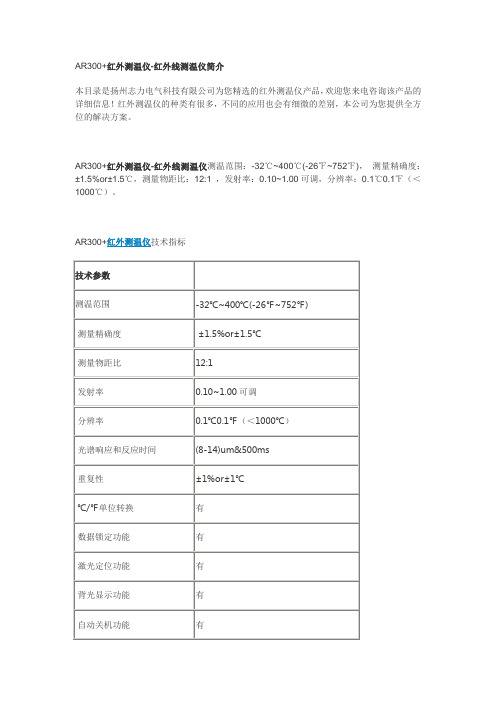
AR300+红外测温仪-红外线测温仪测温范围:-32℃~400℃(-26℉~752℉),测量精确度:±1.5%or±1.5℃,测量物距比:12:1 ,发射率:0.10~1.00可调,分辨率:0.1℃0.1℉(<1000℃)。
AR300+红外测温仪技术指标
非接触红外测温仪和传统的接触类测温仪有何不同
产品别名:红外线测温仪,红外线测温仪型号,远红外线测温仪,手持式红外线测温仪,高温红外线测温仪,便携式红外线测温仪,工业红外线测温仪,红外线测温仪价格,红外测温仪,便携式红外测温仪,红外线体温计,人体红外线测温仪,非接触式红外线测温仪,红外测温仪-红外线测温仪,红外测温仪-红外线测温仪。
本着用户第一的宗旨,扬州志力公司积极做好售前、售中、售后服务,我们郑重承诺:用心做产品、满意在服务。
尊敬的客户:
感谢您关注我们的产品,本公司除了有此产品介绍以外,还有红外线测温仪,变频串联谐振试验装置,大电流发生器,真空滤油机厂家,耐电压测试仪,无线高压核相仪等等的介绍,您如果对我们的产品有兴趣,欢迎来电咨询。
谢谢!。
2021年多功能电力仪表产品使用手册
多功能电力仪表产品使用手册- 13 -一、概述多功能电力表是一种具有测量、显示、数字通讯和输入、输出等的多功能仪表。
能对电网中的电流、电压、功率、电能、频率、功率因数等多个电参数进行测量。
带电能脉冲输出和485通信。
大屏幕液晶显示。
有多种扩展功能可供选择:口4路开关量输入;口4路开关量输出;口4路变送量输出。
多功能电力表具有很高的性能价格比,能替代传统的多个测量仪表,方便现场布线,提高系统的可靠性。
Modbus通讯规约,方便计算机编程设置或读取数据。
广泛应用于各种配电、计量和各种电量采集、传输系统中。
二、技术参数:性能参数输入测量显示接线方式三相三线、三相四线电压额定值AC100V、400V过负荷测量:1.2 倍瞬时:2 倍 10s 功耗<1VA (每相)阻抗>300kΩ精度精度等级0.5电流额定值AC1A、5A过负荷持续:1.2 倍瞬时:10 倍 10s 功耗<0.4VA (每相)阻抗<20mΩ精度RMS 测量,精度等级0.5频率40~60Hz,精度0.1Hz功率有功、无功、视在功率,精度0.5% 显示可编程设置、切换LCD 显示电能四象限计量,有功精度0.5%,无功精度1%电源工作范围AC DC 80~265V AC220V输出可编程功耗≤5VA数字接口RS-485、MODBUS-RTU 协议脉冲输出1或2 路电能脉冲输出模拟量输出4 路模拟量变送输出,4~20mA环境工作环境-10~55℃储存环境-20~75℃安全耐压输入和电源>2kV,输入和输出>2kV,电源和输出>1kV绝缘输入、输出、电源对机壳>5M1辅助电源:仪表电源采用AC220V和AC DC电源,建议采用AC 220V电源。
请保证所提供的电源适用于该系列的产品,以防止损坏产品。
注:采用交流供电时,建议在火线一侧安装1A保险丝。
电力品质较差时,建议在电源回路安装浪涌抑制器防止雷击,以及快速脉冲群抑制器。
RadStar RS300操作指南说明书

RS300FEATURESIndicator LightPower Jack PrinterPort •12or 24-hour start time delay option •Internal memory to retain data Print Button Clear Button Key Switch•Accurate measurement in a wide range of temperatures and relative humidity •Nominal sensitivity:16cph/pCi/LTable of Contents2.0TURNING UNIT ON :2.1Insert key into unit and turn it one click to the right to the [Keypad On ]position.The unit will beep.3.0ERASING STORED DATA:3.1Press and hold the [Hold to Clear ]button.There will be an audible tone coming from the unit when this is done.Release the [Hold to Clear ]button after the tone stops.There will be a short “beep”to signify that the memory has been erased.This is done to erase any prior test that has been stored in the memory so that the unit will test from the first hour.If this is not done,the unit will start testing from the hour that it was shut off on the last test.1.0SETTING UP THE RS300:1.1Plug power adapter that is marked “RadStar Power Supply”into any 120VAC outlet.1.2Plug free end of power adapter into left side of RS300-Green LED should come on.This tells you that the NiCad batteries are charging.Power cord should be left plugged in at all times during a radon test to ensure that the batteries remain charged.If there is no power available,such as in new construction,the unit may be run for a typical 48hr test on the batteries alone as long as the unit has been charging with the power adapter over night.4.0MONITORING FOR RADON GAS :4.1You may begin monitoring for radon gas by turning the keyswitch to the [Measure On ]position.The key may be removed in this position to prevent tampering with the unit.4.2The red LED next to the [Measure On ]logo will stay on for forty seconds then go out.This is a normal condition.Every thirty seconds after there LED will blink.This is a normal condition.Note:When the key is turned to the [Measure On ]position to start a new radon test and the unit “beeps”,it means that the data needs to be erased from the prior test.See section 3.0.Note:Test duration per EPA Protocols must be at least 48hours.5.0OBTAINING A READING FROM THE RS300:5.1Any time during or after a test turn the keyswitch to[Keypad On]position.Note:To continue testing at anytime when the keyswitch has been turned to the [Keypad On]or the[Off]position,simply turn the keyswitch to[Measure On] position.Note that the unit will“beep”to signify continued testing.Note:When a test is continued by going from[Keypad On]to[Measure On]the hour that you were testing in starts over again.Also note that if you try to look at the readings before the first hour is up the PC or printer will read:“No Data”.6.0SETTING UP THE OPTIONAL PRINTER:6.1Plug the AC/DC adapter(the one marked“Printer Power Supply”)into any120VAC outlet.Plug the power jack from the adapter into the back of the printer.6.2Connect the D-Sub cable supplied with the unit to the printer and the RadStar. 6.3Turn the printer on via the rocker switch.The red LED on the printer should come on.7.0OBTAINING A TEST REPORT PRINTOUT:7.1After completing a test turn the keyswitch to[Keypad On]position.7.2Press and hold down[Print]button until unit beeps.The unit will print the test report.See Fig.A(p.6)for an explanation of the printout.Note:If you try to get a printout within the first hour of testing,the printer will display“No Data to Print”.7.3To obtain multiple printouts,simply press the[Print]button again.9.0TRANSPORTING THE RADSTAR TO A PC OR PRINTER :9.1If desired,you may transport the RadStar to a PC or printer to retrieve the data.Turn keyswitch to [Off ]position remove key and disconnect power supply.When your destination is reached,simply insert key into unit and turn to [Keypad On ]and print or 8.0DOWNLOADING DATA FROM THE RADSTAR:The RadStar comes with a Data Capture Utility Program (Windows XP and Vista compatible),and a USB/Serial Adapter Cable with driver.The accompanying RadStar Documentation Library describes the set-up and operation of these items.You may also view the Documentation and download the Program from the AccuStar Labs website .8.1Install the RadStar Data Capture Utility Program and cable driver on your PC.In the Program,setup the correct RadStar model number and the correct COM port.Refer to the RadStar Documentation Library for specific instructions.8.2Connect the PC cable to the Print Port on the RadStar,and to your PC.Turn the RadStar keyswitch to [Keypad On ]position.8.3In the Data Capture Utility Program on your PC,click Download Data.The Set Delay menu will appear.No Delay,12-Hour Delay,or 24-Hour Delay must be selected.Note:To meet EPA protocols minimum test durations are 48,60and 72hours for No Delay,12-Hour Delay,or 24-Hour Delay respectively.On the RadStar,press the [Print]button once.The data will download to the PC.Note:Clicking Download Data on the PC after pressing Print on the RadStar Unit will result in incomplete data and an error message when exporting results to the Excel Chart.Note:If you try to download data from the RadStar within the first hour of testing,the PC will display "No Data".8.4The test data downloaded into the Data Capture Utility can then be exported into a text file,comma delimited file or Excel chart.README files with the software describe the set-up and operation of the Data Capture Utility.Data Exported depends on the Delay selected when the Data was downloaded.“No Delay”-All data from hour 001is exported.Hours 001-004are ignored when cal-culating Average,Min and Max.Plot on Excel chart starts at hour 005.“12-Hour Delay”-All data from hour 013is exported.Hours 013-016are ignored when calculating Average,Min and Max.Plot on Excel chart starts at hour 017.“24-Hour Delay”-All data from hour 025is exported.Hours 025-028are ignored when calculating Average,Min and Max.Plot on Excel chart starts at hour 029.FIGURE AEXAMPLE RS300TEST RESULT PRINTOUTManufactured byRadonAway3Saber Way Ward Hill,MA01835Mode:Continuous Monitor,Passive Diffusion Principle of Operation:Pulse Mode Ionization Chamber Minimum Sensitivity:0.27cpm/pCi/L (minimum 64alpha counts per hour @4pCi/L)Units:picoCuries per liter (pCi/L)Dynamic Range:0.5to 150pCi/L Linearity:+/-10%Best Straight Line Data Storage (Nonvolatile):Up to 240hourly readings,wrap on over-run.Power:120VAC 60Hz Transformer,8days rechargeable battery operation.Indicators:Green AC Power LED,Red Testing LED Key Switch:3Position,Removable Key [Off ][Keypad On ][Measure On ]Pushbuttons:Momentary [Print ][Hold to Clear ]Communications:RS-232port for printing or computer uploads Tamper Protection:Tilt switch,AC power fail detection,key switch lock-out.Operating Range:Temperature 50F –90F Humidity 0-80%,non-condensing Size:Height 7inches (includes Carrying Handle)Width 8inches Depth 4½inches Weight 2½pounds Color:Green/Black Mounting:(2)¼”x 20Threaded Tripod MountsRS300Instrument Specifications Manufactured by RadonAway 3Saber Way Ward Hill,MA01835Technical Support,Calibration and Repair Service.800-767-3703M-F 8:30am -5:30pm ET。
TWA—300K型低流量空气采样器操作指南及技术详情 空气采样器操作规程

TWA—300K型低流量空气采样器操作指南及技术详情空气采样器操作规程一、产品介绍TWA—300K型低流量空气采样器,不仅适用于多种吸取管的采样,更是固体吸附管的理想仪器。
固体吸附管(包括活性炭管和硅胶管等)即可用作长时间采样,又可用作短时间采样,即可用于定点采样,又可用于个体采样,既可用采集各种有机蒸汽,又可采集各种无机气体和蒸汽;既可用于卫生标准zui高容许浓度(MAC)的监测配套,又可用于时间加权平均浓度(TWA)监测配套。
因此,它已越来越广泛地用于劳动卫生和环境卫生的监测和评价。
二、技术参数1、抽气压力:13000Pa2、流量范围:20~500ml/min3、流量精度:5%4、稳定性:5%5、定时精度:1%6、环境温度:—5~50℃7、工作状态:断续或连续8小时采样8、电源:交直流两用,交流220V10V 50Hz 直流6节5号电池或者充电电池。
9、重量:0.5Kg10、外形尺寸:1378845(mm)四、操作指南1.按键功能说明:ON/OFF键开关键, H键小时设定键,M键分钟设定键,OK键开始/短时间停止键。
2.开机显示00:00:00闪亮,在没有按键操作的状态下闪亮3分钟后自动关机。
3.开机后按H键一次小时数字加一、按着不放小时数字累加,zui大可设定99小时。
4.按M键一次分钟加一、按着不放分钟累加,zui大可设定59分钟。
5.设定过程中,连续按OK键3秒可以清零。
6.设定好定时时间,按OK键开始采样,如没有按OK键运行时,过1分钟后自动关机。
7.采样过程中按OK键一次可以短时间停止,再按一次连续采样。
8.采过程中如发觉电池电压不足可直接插上充电器连续采样。
9.采样结束后关闭主电源开关,如需连续采样请在关闭主电源开关30秒后开机。
10.充电:仪器需要充电时插上充电器,充电器指示灯为红灯表示正在充电,充电时间大约8小时。
空气采样器的原理和应用空气采样器系统包括探测器和采样网管,探测器由吸气泵、过滤器、探测腔、掌控电路、显示电路等构成。
LQ-300KIII用户手册.
首先感谢您购买 Jolimark®打印机。本打印机是一部 24 针 80 列点阵打印机,能满足多功能打印的 要求,全面适用于税务、邮政、电信、公安、医院、保险、金融、证券、海关、酒店、航空和运输等 行业。
下面介绍本打印机的主要特点:
简易安装打印纸
本打印机的纸张安装设计使您能够轻松自如地操作,快速地安装打印纸,节省您的时间。
产品兼容性
命令兼容 Epson ESC/PK2。
增强的汉字字库
内置 GB18030-2000 汉字大字库。
ii
目录
目录
安全指引 ............................................................................................................................................................ I
注:本手册内容如有更改,恕不另行通知。
* 本产品所有部件均为可回收设计,当用户需要废弃本产品时,本公司负责无偿 回收,具体处理方法请联系本公司售后服务部。
i
前言
警告、告诫和注意
使用本手册时有如下约定: 警告: 必须照办,以免伤害人体。
告诫: 必须遵守,以免损坏打印机。
注意: 包含关于操作打印机的重要信息和有用提示。
第一章 安装打印机 .....................................................................................................................................1
1.1 打印机的拆封 .....................................................................................................................................1 1.2 选择打印机的安放位置 .....................................................................................................................1 1.3 安装打印机 .........................................................................................................................................2
CLASSIC 300D Kubota操作手册(适用于编码为11112、11113、11243等的
CLASSIC ®300DKUBOTAMANUALFor Machines with Code Numbers 11112,11113,11243,11244,11413,11414,11474,11475IM843-CNovember,2008Safety Depends on YouLincoln arc welding equipment is designed and built with safety in mind.However,your overall safety can be increased by proper installation ...and thoughtful operation on your part.DO NOT INSTALL,OPERATE OR REPAIR THIS EQUIPMENT WITHOUT READING THIS MANUAL AND THE SAFETY PRECAUTIONS CONTAINED THROUGHOUT.And,most importantly,think before you act and becareful.Copyright ©Lincoln GlobalInc.AUG06Jan,07vvfor selecting a QUALITY product by Lincoln Electric. We want you to take pride in operating this Lincoln Electric Company product ••• as much pride as we have in bringing this product to you!Page Installation.......................................................................................................Section A Technical Specifications........................................................................................A-1 General Description...............................................................................................A-2 Design Features....................................................................................................A-2 Pre-Operation Installation......................................................................................A-3 Safety Precautions..........................................................................................A-3Exhaust Spark Arrester...................................................................................A-3Location/Ventilation.........................................................................................A-3Machine Grounding.........................................................................................A-3Lift Bail............................................................................................................A-3Trailers............................................................................................................A-4Polarity Control and Cable Sizes....................................................................A-4 Pre-Operation Service...........................................................................................A-4 Oil....................................................................................................................A-4Fuel.................................................................................................................A-4Cooling System...............................................................................................A-4Battery Charging.............................................................................................A-5 ________________________________________________________________________ Operation.........................................................................................................Section B Engine Operation...................................................................................................B-1 Starting The Kubota V2203M Engine.............................................................B-1Cold Weather Starting.....................................................................................B-1High Altitude Operation...................................................................................B-1Stopping the engine........................................................................................B-1Break-In...........................................................................................................B-1 Welder Operation...................................................................................................B-2 Duty Cycle.......................................................................................................B-2Control of Welding Current..............................................................................B-2Idler Operation................................................................................................B-3Auxiliary Power...............................................................................................B-3Fuel Consumption Data..................................................................................B-3 ________________________________________________________________________ Accessories.....................................................................................................Section C Optional Features (Field Installed)........................................................................C-1 Wire Feed Options.................................................................................................C-2 ________________________________________________________________________ Maintenance....................................................................................................Section D Safety Precautions................................................................................................D-1 General Instructions..............................................................................................D-1 Cooling System.....................................................................................................D-1 Bearings................................................................................................................D-1 Commutator and Brushes.....................................................................................D-1 Idler Maintenance..................................................................................................D-2 Nameplates...........................................................................................................D-2 Purging Air from Fuel System................................................................................D-2 Engine Service Chart............................................................................................D-3 GFCI Receptacle Testing and Restting Procedure...............................................D-4 ________________________________________________________________________ Troubleshooting..............................................................................................Section E Safety Precautions.................................................................................................E-1 Welder Troubleshooting........................................................................................E-2 Electronic Idler Troubleshooting Guide...........................................................E-3,E-4 Engine Troubleshooting Guide ...............................................................E-5, E-6,E-7 ________________________________________________________________________ Diagrams..........................................................................................................Section F Wiring Diagrams.......................................................................................F-1 thru F-5 Dimension Print......................................................................................................F-6TECHNICAL SPECIFICATIONS - CLASSIC 300D KUBOTA*Based on a 10 min. period.(1)Output rating in watts is equivalent to volt-amperes at unity power factor. Output voltage is within ± 10% at all loads up torated capacity. When welding, available auxiliary power will be reduced.(2)Height to top of exhaust elbow.Larger machines with a capacity of 350 amperes and higher, which are operated at low or no-load condi-tions for extended periods of time are especially sus-ceptible to the conditions described above. To accomplish successful engine break-in, most diesel-powered equipment needs only to be run at a reason-ably heavy load within the rating of the welder for some period of time during the engineʼs early life. However, if the welder is subjected to extensive light loading, occasional moderate to heavy loading of the engine may sometimes be necessary. Caution must be observed in correctly loading a diesel/generator unit.1. Connect the welder output studs to a suitableresistive load bank. Note that any attempt to short the output studs by connecting the welding leads together, direct shorting of the output studs, or connecting the output leads to a length of steel will result in catastrophic damage to the generator and voids the warranty.2. Set the welder controls for an output current andvoltage within the welder rating and duty cycle.Note that any attempt to exceed the welder rating or duty cycle for any period of time will result in catastrophic damage to the generator and voids the warranty.3. Periodically shut off the engine and check thecrankcase oil level.IDLER OPERATIONStart the engine with the “Idler” switch in the “High”position. Allow it to run at high idle speed for several minutes to warm the engine. See Specifications for operating speeds.The idler is controlled by the “Idler” toggle switch on the welder control panel. The switch has two posi-tions as follows:1.In the “High” position, the engine control unit increases the engine to high idle speed.2. In the “Auto” / position, the idler oper-ates as follows:a.When welding or drawing power for lights or tools (approximately 100 watts minimum) from the recep-tacles, the engine operates at high idle speed.b.When welding ceases or the power load is turned off, a preset time delay of about 15 seconds starts.This time delay cannot be adjusted.c.If the welding or power load is not re-started before the end of the time delay, the engine control unit reduces the engine to low idle speed.AUXILIARY POWERStart the engine and set the “IDLER” control switch to the “High Idle” mode. Voltage is now correct at the receptacles for auxiliary power. This must be done before a tripped GFCI receptacle can be reset proper-ly. See the MAINTENANCE section for detailed infor-mation on testing and resetting the GFCI receptacle.The AC auxiliary power, supplied as a standard, has a rating of 3.0 kVA of 115/230 VAC (60 hertz).With the 3.0 kVA, 115/230 VAC auxiliary power, one 115V duplex and one 230V duplex, grounding type receptacle are provided. The circuit is protected with circuit breakers.The rating of 3.0 kVA permits a maximum continuous current of 13 amps to be drawn from the 230 volt duplex receptacle. Or a total of 26 amps can be drawn from the 115 volt duplex receptacle. The 115 volt duplex receptacle has a configuration which permits 20 amps to be drawn from either half. The total com-bined load of all receptacles is not to exceed 3.0 kVA.An optional power plug kit is available. When this kit is specified, the customer is supplied with a plug for each receptacle.When the High Speed Adjustment knob is in the MIN position, the frequency of the AC auxiliary output may be reduced to approximately 55 Hertz. It is recom-mended that the High Idle Speed Adjustment knob should be in the MAX position when using the AC auxiliary output.Remote Control Kit (K924-5) - Contains remote control rheostat and 100 ft. (30.5 m) cable for adjust-ing the OCV at the welding site. (For Codes 10911 and above.)Remote Control Kit (K2464-1) - Contains remote control rheostat (for adjusting the CC “STICK” OCV), and 100ft.(30.5m) cable. (See Wiring/Connection Diagram Section F)TIG OPTIONSTIG Module (K930-2) - Provides high frequency and shielding gas control for AC and DC GTAW (TIG) welding applications. Its compact case is designed for easy carrying, complete with a handle. High frequen-cy bypass is built in. The K936-4 control cable is required.PTA-26V TIG Torch (K1783-9) - Air cooled 200 amp-torch equipped with valve for gas flow control. 25Ft. length.Magnum Parts Kit For PTA-26V TIG TorchKP509Control Cable (K936-4) (required for TIG Module) -Control Cable for connecting the K930-2 Tig Module.Arc Start Switch (K814) (required for TIG Module) -Comes with a 25ft.(7.6m) cable. Attaches to the TIG torch for convenient finger control.Contactor Kit (K938-1) (required for TIG Module) -Provide “Cold” tungsten Tip when welding with the TIG Module.Control Cable Extension (K937-45) - Allows the TIG Module to be operated at distances up to 200 ft. from the power source.Available in 45 ft. (13.7m).Water Valve Kit (K844-1)- For use with a water-cooled TIG torch. Installs inside TIG Module.WIRE FEED OPTIONSWire Feed Module (K623-1) - Provides constant voltage (CV) output with improved arc stability for Innershield welding. Excellent for MIG welding. Recommended wire feeders are the LN-7, LN-23P and LN-25. (Factory installed on the K1643-6).LN-25 Wire Feeder (K449)-Portable CC/CV unit for flux-cored and MIG welding. Includes Gas Solenoid & Internal Contactor. Requires Wire Feed Module.Remote Voltage Control Kit for LN-25 (K444-2) Provides 25 ft. (7.5m) of remote output voltage control and output jumper (2 and 4) for machines having 14 pin MS-type connector.Magnum® 350 Innershield Gun (for LN-25)(K126-2)-For self-shielded wire with 15 ft. (4.5m) cable. For .062-3/32” (1.6-2.8mm) wire.Magnum® 300 MIG Gun for LN-25K1802-1 - With 15 ft. (4.5m) cable. For .035”-.045” (0.9-1.2mm) gas shielded (Includes Connector Kit).LN-23P Wire Feeder (K316L-1)-Portable CV unit for Innershield pipe welding. Control cable operates con-tactor inside Wire Feed Module for “cold” electrode. Requires LN-23P Adapter Kit (K350-1) and Gun and Cable Assembly.LN-23P Adapter Kit (K350-1)-Required to adapt LN-23P to any Lincoln power source. Makes 14 pin con-nection at power source.Magnum® 250 Innershield Gun (for LN-23P) (K355-10)-For lighter weight and easier handling. Rated 250 amps, 60% duty cycle. For .068 through 5/64” (1.7 through 2.0 mm) Innershield wire and includes reduced speed switch. For pipewelding, an M11476 62° gun tube is recommended.62° gun tube for PipeWelding (KP1909-1)-Recommended modification for K355-X or K345-X guns with 90° gun tubes. Compatible with K126-1,-2 K264-8 and K355-10.Magnum Spool Gun(K487-25)-Hand held semiauto-matic wire feeder requires SG Control Module. 25 ft.(7.6m)length.SG Control Module (K488) (For Magnum Spool Gun) -The interface between the power source and the spool gun. Provides control of wire speed and gas flow.Input Cable(K691-10) ( For SG Control Module) -For Lincoln engine drives with 14-pin MS-type con-nection provides separate 115V NEMA receptacle and output stud connections. 10 ft. (3.1m)length.Air Bleeding ValveGFCI RECEPTACLE TESTING AND RESET-TING PROCEDUREThe GFCI receptacle should be properly tested at least once every month or whenever it is tripped. To properly test and reset the GFCI receptacle:• If the receptacle has tripped, first carefully remove any load and check it for damage.• If the equipment has been shut down, it must be restarted.• The equipment needs to be operating at high idle speed and any necessary adjustments made on the control panel so that the equipment is providing at least 80 volts to the receptacle input terminals.• The circuit breaker for this receptacle must not be tripped. Reset if necessary.• Push the "Reset" button located on the GFCI recep-tacle. This will assure normal GFCI operation.• Plug a night-light (with an "ON/OFF" switch) or other product (such as a lamp) into the GFCI receptacle and turn the product "ON".• Push the "Test" button located on the GFCI recepta-cle. The night-light or other product should go "OFF".• Push the "Reset" button, again. The light or other product should go "ON" again.If the light or other product remains "ON" when the "Test" button is pushed, the GFCI is not working prop-erly or has been incorrectly installed (miswired). If your GFCI is not working properly, contact a qualified, certified electrician who can assess the situation, rewire the GFCI if necessary or replace the device.This Troubleshooting Guide is provided to help you locate and repair possible machine malfunctions.Simply follow the three-step procedure listed below.Step 1.LOCATE PROBLEM (SYMPTOM).Look under the column labeled “PROBLEM (SYMP-TOMS)”. This column describes possible symptoms that the machine may exhibit. Find the listing that best describes the symptom that the machine is exhibiting.Step 2.POSSIBLE CAUSE.The second column labeled “POSSIBLE CAUSE” liststhe obvious external possibilities that may contribute to the machine symptom.Step 3.RECOMMENDED COURSE OF ACTIONThis column provides a course of action for the Possible Cause, generally it states to contact your local Lincoln Authorized Field Service Facility.If you do not understand or are unable to perform the Recommended Course of Action safely, contact your local Lincoln Authorized Field Service Facility.HOW TO USE TROUBLESHOOTING GUIDEService and Repair should only be performed by Lincoln Electric Factory Trained Personnel.Unauthorized repairs performed on this equipment may result in danger to the technician and machine operator and will invalidate your factory warranty. For your safety and to avoid Electrical Shock, please observe all safety notes and precautions detailed throughout this manual.__________________________________________________________________________T E : T h i s d i a g r a m i s f o r r e f e r e n c e o n l y . I t m a y n o t b e a c c u r a t e f o r a l l m a c h i n e s c o v e r e d b y t h i s m a n u a l . T h e s p e c i f i c d i a g r a m f o r a p a r t i c u l a r c o d e i s p a s t e d i n s i d e m a c h i n e o n o n e o f t h e e n c l o s u r e p a n e l s . I f t h e d i a g r a m i s i l l e g i b l e , w r i t e t o t h e S e r v i c e D e p a r t m e n t f o r a r e p l a c e m e n t . G i v e t h e e q u i p m e n t c o d e n u m b e r .N O T E : T h i s d i a g r a m i s f o r r e f e r e n c e o n l y . I t m a y n o t b e a c c u r a t e f o r a l l m a c h i n e s c o v e r e d b y t h i s m a n u a l . T h e s p e c i f i c d i a g r a m f o r a p a r t i c u l a r c o d e i s p a s t e d i n s i d et h e m a c h i n e o n o n e o f t h e e n c l o s u r e p a n e l s . I f t h e d i a g r a m i s i l l e g i b l e , w r i t e t o t h e S e r v i c e D e p a r t m e n t f o r a r e p l a c e m e n t . G i v e t h e e q u i p m e n t c o d e n u m b e r .JapaneseChineseKoreanArabicREAD AND UNDERSTAND THE MANUFACTURER’S INSTRUCTION FOR THIS EQUIPMENT AND THE CONSUMABLES TO BE USED AND FOLLOW YOUR EMPLOYER’S SAFETY PRACTICES.SE RECOMIENDA LEER Y ENTENDER LAS INSTRUCCIONES DEL FABRICANTE PARA EL USO DE ESTE EQUIPO Y LOS CONSUMIBLES QUE VA A UTILIZAR, SIGA LAS MEDIDAS DE SEGURIDAD DE SU SUPERVISOR.LISEZ ET COMPRENEZ LES INSTRUCTIONS DU FABRICANT EN CE QUI REGARDE CET EQUIPMENT ET LES PRODUITS A ETRE EMPLOYES ET SUIVEZ LES PROCEDURES DE SECURITE DE VOTRE EMPLOYEUR.LESEN SIE UND BEFOLGEN SIE DIE BETRIEBSANLEITUNG DER ANLAGE UND DEN ELEKTRODENEINSATZ DES HER-STELLERS. DIE UNFALLVERHÜTUNGSVORSCHRIFTEN DES ARBEITGEBERS SIND EBENFALLS ZU BEACHTEN.JapaneseChineseKoreanArabicLEIA E COMPREENDA AS INSTRUÇÕES DO FABRICANTE PARA ESTE EQUIPAMENTO E AS PARTES DE USO, E SIGA AS PRÁTICAS DE SEGURANÇA DO EMPREGADOR.。
一款1 4进阶流动性测量仪器AR2000、AR1000和AR500的使用指南说明书
A DVANCED R HEOMETERAR 2000, AR 1000 & AR 500Guide to Setting Up the RheometerPrepared byFred A. MazzeoOutline 1.Turn on the computer controller.2.Always make sure that the air supply is turned on to the rheometer.3.Remove the black bearing lock by holding it in place while turning thedraw rod knob at the top in a counter-clockwise direction. Once thebearing lock is removed, make sure that the spindle rotates freely.NOTE: When using the AR2000, please ensure that the drive-shaft slidelock is pulled-out.4.Turn on the power to the instrument and, if present, the ETC controller.NOTE: If step 4 is performed before step 3, an alarm will sound and theinstrument controller display will read ‘optical init. fail’. At this pointjust follow step 3 and the alarm will stop.5.Please ensure that the water supply is turned on.6.When instrument has finished the system check, turn on the instrumentcontrol software.7.Go to the I nstrument Status Page to make certain thatcommunication has been established between the computer and theinstrument.8.Instrument Inertia: Determine the instrument inertia by selectingOptions>Instrument>Inertia and run the ‘calibrate’ wizard.9.B e a r i n g F r ic t i o n:S e l e c tc t i o n C o r r eOptions>Instrument>Miscellaneous and make sure that the bearingfriction correction box has a value and the bearing friction correction isactivated.a.If there is no value, perform the bearing fiction correctionprocedure via the wizard, (Rheology Advantage 3.0), or using theHelp>Index under the phrase ‘friction: calibration>determiningbearing friction correction’. When using a version of softwareless than version 3.0, uncheck the bearing friction correction boxlocated within Options>Instrument>Miscellaneous before runningthe calibration procedure.10.Geometry: Attach test geometry by holding it in place while turning thedraw rod knob at the top in a counter-clockwise direction. Choose theappropriate geometry, if the file already exists (Geometry>Open…), orcreate a new geometry by selecting Geometry>New, and follow theguide.11.Geometry Inertia: Calibrate the geometry inertia by following thew i z a r d t h a t i s f o u n d i n t h e Geometry Page>Settings>Inertia: Calibrate.12.Mapping: Perform a mapping on the geometry by using the iconor use Instrument>Mapping. Select either the number of iterations ormapping type within the icon dialog window (Rheology Advantage 3.0)or under Options>Settings>Mapping and Options>Instrument>Miscellaneous: Mapping Type, respectively.a.M apping only needs to be performed when using a flowprocedure and when the lower two decades of torque isnecessary for data acquisition.b.The number of iterations should be set greater than one whentesting a very low viscosity material. When performing a Creepprocedure the number of iterations should be set to 4, if theRecovery step is set to zero. Otherwise, setting the number ofiterations greater than three has diminishing returns in themapping performance.c.The mapping type can be set to fast, standard or precision. It isrecommend that ‘standard’ should be selected for most materials,but for more critical measurements, ‘precision’ mapping is moresuited.13.Temperature System Selec tion: Select the temperature system andattach the appropriate bottom assembly.a.For AR1000/500/QCR instruments, the temperature read andcontrol must be set to the appropriate temperature system. Thisis accomplished by choosing Options>Instrument>Temperature:Temperature Read and Temperature Con trol setting both to‘Peltier’, if using the Peltier Plate, or ‘Temperature System’ if anyother system is being used.b.This selection is not necessary for the AR2000.14.Zero Gap: Zero the gap by choosing the zero gap icon , or byselecting In strumen t>Gap>Zero Gap and follow the directions on screen.a.If equipped with normal force, there are two options that onecan used to zero the gap, deceleration or normal force.Generally, the normal force method is recommended. Thischoice is made in the Options>Instrument>Gap>Gap Zero Mode:Normal Force. Set the value equal to 1 N.NOTE : The upper geometry should be at the testing temperature before zeroing the gap. This will account for the change in dimensions due to the coefficient of thermal expansion of the testing geometry/system.15.Gap Compensation: If you have the normal force option, you canobtain the gap compensation value by using the gap compensation wizard located in the Geometry Page >Settings (Rheology Advantage 3.0) or by performing an oscillation temperature ramp (torque of 0.1 µNm @a frequency of 1 Hz conducted at a ramp rate of 2°C/min) under globalnormal force control (1N +/- 0.1, 1000 µm up/down, compression, set initial value) with a conditioning step temperature equal to the starting value of the temperature range of the experiment with an equilibration time equal to 5 minutes. Plot the data and then fit a straight line to the graph of Gap vs. Temperature. The slope must be then entered in the Option s>In strumen t>Temperature: Temperature Calibration region within the cell located to the right of the appropriate temperature system. The gap compensation check box should be activated, which is located within the Options>Instrument>Temperature dialog window.If the normal force option is unavailable, then predetermined valuesmust be entered.NOTE: The gap compensation value must be set to zero before this step is performed.NOTE: If controlling normal force throughout an experiment, the gap compensation value is recommended to be activated.NOTE: Gap Compensation needs only to be used when testing over a temperature range.NOTE: Zero the normal force before running the gap compensation test.16.Procedure: Set up procedure by selecting the appropriate file, ifpreviously created, by choosing Procedure>Open or create a new procedure by selecting Procedure>New. The procedure can be adapted in the Procedure Page17.Notes: Enter sample information within the Notes Pageor by selecting Notes>New.18.Sample Loading: Load sample, lower geometry to appropriate gap andtrim if applicable (for additional help, go to Help>Video Clips: Loading and Trimming a Sample).a.The gap can be set by three different methods.i.Manually enter the desired gap by selecting the enter gapicon or by selecting Instrument>Gap>Enter Gap…ii.Automatically have the instrument go to the gap value entered in the Geometry Page >Dimensions by using thego to gap icon or select Instrument>Gap>Go ToGeometry Gap.iii.Manually raise or lower the gap by using theicons. NOTE: These icons are only available when in theInstrument Status Page.19.Run Test: Run test by selecting the run experiment icon .Instrument Inertia (see 8)Monthly Bearing Friction Correction (see 9)MonthlyGeometry Inertia (see 11)Once during the geometry setupVerification of value isrecommended daily, but notrequiredMapping (see 12 a, b, c)Once daily (if same geometry)Every time the geometry ischangedZero Gap (see 14)Every time geometry isremoved/replacedGap Compensation (see 15)Once if using samegeometry/heating systemRun Standard OilMonthly Table 1.CalibrationGuide。
光华K300说明书
4. 传感器信号是一个与平均流速成精确线 性关系的电压。
5. 测量结果与流速分布及液体的压力、温 度、密度、粘度、电导率(不小于最低电导率)等物 理参数无关, 所以测量精度高, 工作可靠。
K300
安装使用说明书
目录
0 产品编码说明 1 综述
1.1 概述 1.2 测量原理 2 技术数据
2.1 K300的品种 2.2 机械数据 2.3 电气参数 2.4 测量精度 2.5 外形尺寸与重量 2.6 铭牌 3 电路方框图和工作原理 4 结构 4.1 传感器部分 4.1.1 传感器 4.1.2 电极 4.1.3 接地环 4.2 转换器部分 5 安装 5.1 安装要求 5.2 PTFE村里传感器的安装 5.3 接地 5.4 电源连接 5.5 名接24V交流电源 5.6 电源电压的选择历 5.7 信号输出 5.8 V/R测量 6 调试与运行
触点形式)
24
10 7.4 电隔离电流信号输出GT300
25
10 7.5 具有频率输出的电隔离的电流输出
11 GTF30026
26
11 8 功能测试
29
12 8.1 测试转换器方法
29
12 8.2 励磁电流检查方法
30
13 9 维护和故障查找
31
14 9.1 日常维护
31
14 9.2 调换电路板
31
衬里材料
电极材料
硬橡胶 H 不锈钢0Cr18Ni12Mo2Ti
V4A
氯丁橡胶 Ne 哈氏合金B
HB
聚四氟乙烯 T
哈氏合金C
HC
CCI K.K. 用户手册

指导手册AB300型控制阀AB300型阀指导手册索引编号. 目录页1. 控制阀的安装 (1)1.1 与安装有关的一般注意事项 (1)1.2 阀的安装(焊接到管路上) (1)1.3 管路的清洗 (1)2. 阀体的检修 (2)2.1 阀体与阀帽的拆卸 (2)2.2 阀帽的检修过程 (2)2.3 阀帽的安装过程 (2)3. 内部阀的检查过程 (3)4. 内阀的检测与维护过程 (3)4.1 内阀间隙的控制 (3)5. 安装内阀的过程 (4)5.1 压盖填料的安装过程 (4)6. 排除故障的措施 (5)7. 控制阀的操作 (6)1. 控制阀的安装在安装之前,请通读本安装手册。
1.1 与安装有关的一般注意事项(1) 安装阀的管路应该足够大,足以承受阀中产生的较高的压力损耗。
(2) 阀应垂直朝上安装,且应在阀的入口和出口处加以支撑,以承受阀和管路的重量。
(3) 不要固定执行机构如隔膜片、盖等。
(4) 在将阀安装到管路上之前,首先应通过阀体上雕刻的印记或铸造印记确定液体流动方向,然后才将阀安装到管路上。
1.2 阀的安装(焊接到管路上)就焊接热或焊后热处理而言,在实施这种作业时应该注意下列事项。
·如果要进行焊后热处理作业,则只在阀体的入口和出口处使用隔热材料,而不要对整个阀体进行隔热。
1.3 管路的清洗(1) 内阀的阀塞和阀笼之间的间隙是很小的,所以阀中夹杂非常小的杂质都会引发故障。
因此,应仔细清洗管道。
(2) 由于阀体的底部是空的,因此杂质容易聚集于此。
应充分地冲洗管道。
(3) 冲洗一般在阀完全打开的情况下进行,然而,最好的清洗方法是在卸下内阀后再进行清洗。
如果在卸下内阀后再进行清洗,则应遵循以下措施。
要非常小心地进行这种作业,不要损坏阀笼和阀体之间的接触面。
2. 阀体的检修2.1 阀体与阀帽的拆卸(1) 在拆卸阀帽之前,应先拆卸掉固定压盖填料的螺母。
同时,还应拆卸掉密封压盖随动件以及填料函。
(2) 用填料夹具将压盖填料拆下。
宾得R-300全站仪操作手册
PowerTopoLite 的屏幕可以由“选项设定”进行变换,这里显示 了出厂缺省设置 R-300 仪器有一个“PENTAX”的项目名,除非用户启用新的项 目名,所测得的数据均存储在“PENTAX”项目名的文件夹中。 输 入 X , Y , Z 坐 标 的 范 围 是 “ 00000000.000 ” — — “999999999.998” 输入仪器和目标高的范围是“0000.000”——“9999.998” PC 是点代码列表附加于 PN、XYZ 坐标和 IH,可输入你所希望 的点属性描述。如果点代码在“列表中” ,你可以轻易地从中选 取,再回车[确认],并对其进行编辑,如果点代码存在其它项目 中,则不能用列表调用。 有直角坐标和极坐标两种坐标类型, 与选择直角坐标系时, X0、 T0 偏心与遥测均可进行。 当在 EDM 的粗跟踪设置之下时,R-300 显示的量测距离值为二 位小数, 而在极坐标测距的编辑功能下可显示 3 位小数, 并以 4 位小数发送: 例如:显示值:123.45 编辑时显示:123.450 发送极坐标数据:123.4500 无论是粗跟踪或在精测模式下,直角坐标的显示存储和发送均 为三位小数 在测量和 VPM 功能的作业过程中,可以按 EDM 键改变测量模 式 相同点名的极点可以被存储。
F4
PREF
选定设订
水平角 列表 全部缩放 比例放大 比列缩小 显示 删除
返回测站点水平角设置屏 显示点的选择列表 回到原始大小 放大图形 缩小图形 显示点和点、点和图形、点名或全部信息 显示点的删除屏 显示点号许找屏可以输入点号 自由建站时允许增加更多点 开始计算自由设点 显示下一已知点坐标设置屏 显示目标点屏 选择目标状态 选择 EDM 的设置 选择当前项目所有点 对选择的点进行排序
浙江中控记录仪AR3100
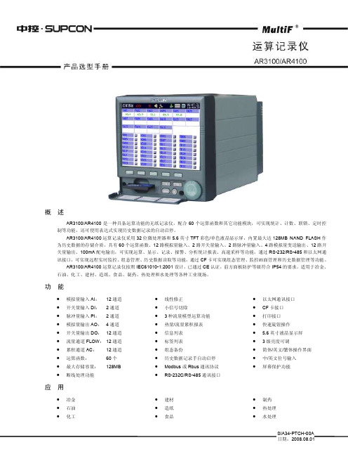
SIA34-PTCH-00A 日期:2008.08.01概 述AR3100/AR4100是一种具备运算功能的无纸记录仪,配合60个运算函数和其它功能模块,可实现统计、计数、联锁、定时控制等功能,还可使用表达式实现历史数据记录的自动启停。
AR3100/AR4100运算记录仪采用32位微处理器和5.6英寸TFT 彩色/单色液晶显示屏,内置最大达128MB NAND FLASH 作为历史数据的存储介质,具有60个运算函数、12路模拟量输入、2路开关量输入、2路脉冲量输入、4路模拟量变送输出、12路开关量输出、100mA 配电输出,可实现运算、显示、记录、报警、分析统计报表、高速采样等功能,通过RS-232/RS-485和以太网通讯接口,可实现远程实时监控、组态管理、历史数据读取等功能,通过CF 卡可实现组态管理、监控画面管理和历史数据管理等功能。
AR3100/AR4100运算记录仪按照IEC61010-1:2001设计,已通过CE 认证,前方面板防护等级符合IP54的要求。
适用于冶金、石油、化工、建材、造纸、食品、制药、热处理和水处理等各种工业现场。
功 能∙ 模拟量输入AI :12通道∙ 开关量输入DI : 2通道 ∙ 脉冲量输入PI :2通道∙ 模拟量输出AO : 4通道 ∙ 开关量输出DO : 12通道 ∙ 流量通道FLOW : 12通道 ∙ 累积通道AC : 12通道 ∙ 运算函数: 60个 ∙ 最大存储容量: 128MB∙断线处理功能∙ 线性修正 ∙ 小信号切除∙ 3种流量模型运算功能 ∙ 热量/流量累积报表 ∙ 信息列表 ∙ 标签列表 ∙ 组态备份∙ 历史数据记录手自动启停 ∙ Modbus 或Rbus 通讯协议 ∙RS-232C/RS-485通讯接口∙ 以太网通讯接口 ∙ CF 卡接口 ∙ 打印接口 ∙ 快速旋钮操作 ∙ 5.6英寸液晶显示屏 ∙ 3级亮度可调∙ 简体/英文/繁体操作界面 ∙ 中/英文位号输入 ∙屏幕保护功能应 用∙ 冶金 ∙ 石油 ∙化工∙ 建材 ∙ 造纸 ∙食品∙ 制药 ∙ 热处理 ∙水处理产品选型手册2 选型代码AR31/ AR41□□-A □-R □□-DI □-PI □-PW □-M □-C □-E □-FC □-FL □-/SP □-/V □□-/V □-/Z □-/□□□ AR31/AR41-型号模拟量输入A-模拟量输出1R-开关量输出2DI-开关量/PI-脉冲量输入3 AR31AR3100彩色01 1路 A0 无 R00 无 DI00 无 运算记录仪 02 2路 A1 1路 R02 2路 DI01 1路开关量输入 AR41AR4100单色03 3路 A2 2路 R04 4路 DI02 2路开关量输入运算记录仪 04 4路 A3 3路 R06 6路06 6路 A4 4路R08 8路 PI00 无 08 8路 R10 10路 PI01 1路脉冲量输入 10 10路 R12 12路PI02 2路脉冲量输入12 12路PW-配电输出 M-存储容量 C-通讯接口4 E-以太网 FC-基本运算PW0 无 M0 32MB C0 无 E0 无 FC0 无 PW1 30mA,24VDC M2 64MB C2 RS-232C E1 有以太网 FC1 表达式 PW2 60mA,24VDC M4 128MB C4 RS-485 PW3 100mA,24VDCCP 串行打印FL-流量运算 /SP-采样模式5 /V-供电电源/V-真空度 /Z-碳势FL0 无 /SP0 1s /VAC (100~240)VAC /V0 无/Z0 无 FL1 流量累积/SP1 500ms /VDC 24VDC /VC 有真空度 /ZC 有碳势 FL2温压补偿/SP2 250ms 与流量累积/SP2L 250ms/SP3 125ms /SP3L 125ms/-语言/SCH 简体中文 /ENG 英文 /TCH 繁体中文注意事项: 1. 当选用模拟量输出时,最多支持8通道模拟量输入;2. 开关量输出默认为常开触点,若需常开常闭触点请另行说明。
300系列操作手册600-1200A
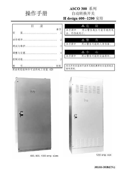
操作手册ASCO 300 系列 自动转换开关H design 600--1200安培目 录 章节 安 装........................... 1 动作顺序........................... 2 测试与维护......................... 3 调整与设置......................... 4 控制功能........................... 5 索 引........................ 封底 须由有经验和许可证的电工安装ATS本手册中危险用以警告高压可能导致的电击、灼伤或死亡。
本手册中警告用以警告可能的人身伤害。
本手册中小心用以警告可能的设备损坏。
有关所有安装细节请参见随机携带的安装图纸及接线图纸。
铭 牌 转换开关铭牌包含每一台ASCO 300系列ATS的参数。
只能在铭牌所示的极限值范围内使用ATS。
目录号标识 典型的目录号如下所示,其中包括各个单元的解释。
例中所示:4极、600安、480伏、I类外箱的ASCO 300系列ATS目录号。
中性线B-转换C-叠加空白-固定相线极数2-单相3-三相电 流60080010001200控制器1-标准1X-带有附件外 箱C-I类F-3R类G-4类*L-12类*空白-无外箱中性线连接电源连接转换开关端子排TB,发电机启动端子及状态接点电源连接薄膜操作面板控制器*只对600-1000安培有效中性线连接ASCO 300系列自动转换开关(ATS)符合UL1008有关ATS的标准。
ASCO 300系列自动转换开关同样符合CSA C22.2第178条有关自动转换开关的标准。
所有控制功能均为UL认可部件,来保证ASCO自动转换开关符合OSHA安全需求,并被电气核查员接受。
ASCO 300系列自动转换开关适用于应急和备用电源系统。
它们符合NEC Article 700 和 UL 1008有关应急系统规定的条件。
Nighthawk Gaming-Router XR300 用户指南说明书
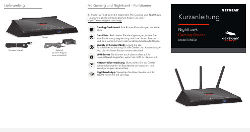
Lieferumfanga. Richten Sie die Antennen aus.Positionieren Sie die Antennen wie in der Abbildunggezeigt, um die beste WLAN-Leistung zu erreichen.wieder an.c. Verwenden Sie das Netzwerkkabel, um Ihr Modem anden gelben Internet-Port an Ihrem Router anzuschließen.Hinweis: Wenn für Ihre Internetverbindungkein Modem erforderlich ist, schließen Sie IhrHauptnetzwerkkabel am gelben Internetanschluss amRouter an.a. Vergewissern Sie sich, dass die WLAN-LED weißleuchtet.mit einem Mobilgerät.d. Starten Sie einen Webbrowser.Der NETGEAR Installationsassistent wird automatischangezeigt.e. Wenn der Installationsassistent nicht angezeigt wird,Einrichten Ihres NetzwerksEinrichten Ihrer Hardware145°SupportVielen Dank, dass Sie sich für dieses NETGEAR Produktentschieden haben. Besuchen Siehttps:///support/, um Ihr Produkt zuregistrieren, Support und Zugriff auf die neuesten Downloadsund Benutzerhandbücher zu erhalten oder unserer Communitybeizutreten. Wir empfehlen, ausschließlich offizielle NETGEARSupport-Ressourcen zu nutzen.Informationen zur Einhaltung der rechtlichen Vorschriften,einschließlich der EU-Konformitätserklärung, finden Sie unter:https:///about/regulatory/.Lesen Sie das Dokument zur Einhaltung rechtlicher Vorschriften,bevor Sie das Gerät an die Stromversorgung anschließen.Verlängern Sie die Garantie und den technischen Support IhresRouters mit NETGEAR ProSupport für Home-Produkte (nur USA).Weitere Informationen finden Sie unterhttps:///home/.。
Topcon RE 300单 objective单焦相机说明书
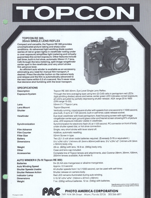
Additive, automatic resetting. 52mm Screw in type.
Two (2) 1.5 volt silver oxide batteries required. (Eveready S-76 or equivalent.) 5W'x35/a"x3W' (141mmx91.5mm x90mm)with lens. 5W'x35fa"x2" (141mm x 91.5mm x 50mm) body only. 28 oz. (820g) with lens. 19.9 oz . (565g) body only.
Lens Lens Mount Shutter
Viewfinder
Synchronization
Film Advance Film Counter Filter Size Battery Dimensions
Weight Other Accessories
Topcon RE 300 35mm, Eye Level Single Lens Reflex.
TOPCON RE 300, 3Smm SINGLE LENS REFLEX
Compact and versatile, the Topcon RE 300 provides uncomplicated picture taking and sharp color renditions. An advanced light emitting diode system (series of red or green lights in viewfinder noting under or over exposure) simplifies light metering and virtually guarantees the correct exposure. Other features include self timer, built-in hot shoe, automatic 55mm f/l.7Iens, CdS through the lens metering, split image rangefinder center spot in the viewfinder, and very short stroke film advance lever.
- 1、下载文档前请自行甄别文档内容的完整性,平台不提供额外的编辑、内容补充、找答案等附加服务。
- 2、"仅部分预览"的文档,不可在线预览部分如存在完整性等问题,可反馈申请退款(可完整预览的文档不适用该条件!)。
- 3、如文档侵犯您的权益,请联系客服反馈,我们会尽快为您处理(人工客服工作时间:9:00-18:30)。
绪 言承蒙惠顾,购得 AR-300K+打印机。
操作手册详细阐述了本机的性能及操作方法,能指导您正确使用。
当您遇到疑问或机器发生故障时,此手册会带给您很大的帮助。
AR-300K+打印机是得实集团与日本西铁城公司合作开发、生产的多功能超高速24针80列通用打印机。
AR-300K+采用高速打印头设计,打印速度高达169汉字/秒,打印针寿命4亿次,600万字符长寿命耐用色带,GB18030中文大字符集硬字库及多款防改写数字、半角英数字及八款条形码打印,使AR-300K+在硬件方面别具特色。
在软件方面,AR-300K+秉承了得实系列打印机的高性能、高兼容性,可兼容所有STAR、EPSON和OKI 打印机,方便的自动撕纸功能及参数设置功能是得实打印机的特色。
打印机针调整和断针自动补偿功能是得实打印机的专利技术。
AR-300K+外观时尚,性能卓越,功能强大,性价比特高,是金融、酒店、医院、连锁药店、大型超市、专卖店等各行业用户的极佳选择。
本产品信息如有更改,恕不另行通知。
本资料仅供参考。
除中国现行法律法规规定,得实集团不承担任何由于使用本资料而造成的直接或间接损失的责任。
得实集团保留最终解释权。
目录第1章安装打印机...................................1-11.1放置打印机......................................1-11.2开箱和检查......................................1-21.3打印机部件......................................1-31.4安装和拆卸色带盒................................1-51.5打印机和主机连接................................1-71.6连接电源........................................1-91.7安装打印驱动程序...............................1-10第2章纸的安装和使用...............................2-12.1选纸............................................2-12.2调校打印头间隙..................................2-12.3安装导纸板......................................2-32.4使用链式纸......................................2-42.5使用单页纸......................................2-8第3章控制面板.....................................3-13.1按钮及其指示灯..................................3-13.2开机功能........................................3-33.3组合功能........................................3-6第4章参数设置.....................................4-14.1如何进行参数设置................................4-24.2系统设置........................................4-34.3纸张设置........................................4-64.4接口设置.......................................4-104.5ESC/P和LQ仿真参数设置..........................4-124.6OKI仿真参数设置................................4-154.7双向测试及纵向校正.............................4-164.8打印针自动调整设置.............................4-204.9打印针补偿设置.................................4-214.10如何恢复出厂设置...............................4-23第5章用户调整设置.................................5-15.1链式装纸页首调整................................5-15.2摩擦装纸页首调整................................5-25.3撕纸位置调整....................................5-3第6章故障和保养...................................6-16.1故障处理........................................6-16.2保养与维护......................................6-6第7章规格.........................................7-17.1打印机规格......................................7-17.2接口接头引脚....................................7-47.3字符集.........................................7-117.4控制码摘要表...................................7-177.4.1 ESC/P和LQ仿真控制码摘要表......................7-177.4.2 OKI仿真控制码摘要表............................7-21附录1:电子信息产品污染控制的说明.....................8-1安全规范使 用 注 意 事 项为了避免受到电击和伤害及防止损坏打印机,在接上电源之前,务请注意以下重要事项:仔细阅读操作手册等说明文件。
打印机必须平放在固定的台面上。
避免震动、碰撞、高温和阳光直射、灰尘等。
请勿将打印机置于潮湿的环境中,请勿让雨水等任何液体沾湿打印机。
打印机应安放在接近插座的地方,方便操作者进行电源插头的拔插操作。
确保电源的电压值与打印机所规定的电压值一致,避免与电冰箱等大功率或有干扰的电器同一电源。
为保证安全操作,三脚插头必须插进三孔交流电源插座中,其中地线必须有效接地。
电源延长线必须为三芯并正确连接,以提供接地。
若交流电源插座与打印机插头不匹配,请更换合适的交流电源插座,以保证人员、设备的安全使用。
连接打印机通讯电缆时,请先关闭打印机和计算机的电源,选用适合的联机电缆将打印机和计算机连接起来,并锁定卡口和旋紧螺丝。
请勿接触打印头外壳,以防止高温伤害。
清洁打印机前,先关闭电源开关,从电源插座拔掉电源插头。
用软棉绒布沾少量中性清洁剂或酒精,轻抺打印机外部。
如遇打印机发生故障,除认可的合格技术员外,不可擅自进行维修工作。
企业公开信息:1.售后服务请致电全国各地得实服务网点电话,或拨打:400-810-9998(手机)800-810-9998(免费)2.产品工作、待机、休眠及关闭状态的最大及最小能耗如下:产品使用状态最大能耗最小能耗工作时 150W 10W待机 5.8W 5.6W休眠 5.7W 5.6W关闭小于0.1W 0 注:只有当产品无任何外接输入电源,才能实现零能耗。
3.如果用户需对产品性能升级或更换模块,请来电咨询,我们将给您详细解答。
4.当您弃置达到使用寿命年限的针式打印机产品时,我们建议您将废弃产品返还给本公司或全国各地得实服务网点,由得实集团作统一处理,以保护生态环境。
5.本产品能使用含50%回收纤维的打印纸进行打印。
第1章安装打印机本章描述如何安装一台新的打印机,步骤如下:放置打印机开箱和检查安装和更换色带盒连接接口电缆连接电源安装打印驱动程序1.1 放置打印机先将打印机放在将要使用的地方,清除打印机所有包装物件(这些包装物件用于保证打印机运输时不受损坏),并妥善保存包装物件及纸箱,以备后用。
在安装打印机之前,首先要确定一个合适的地方放置打印机。
这里“合适的地方”是指:请将打印机平放在工作台上。
避免将打印机置于过热、过度潮湿和灰尘过多的地方。
接上稳定电源,避免与电冰箱之类大功率或有干扰的电器同一电源。
关闭打印机电源开关后,才能拔插电源线,打印机应尽可能放置在接近插座的地方,便于使用。
打印机必须放置在走纸空间足够的地方。
如果用打印机并行接口连接,必须确保电缆长度在2米范围内。
1.2 开箱和检查打开纸箱,对照下图检查箱内部件和附件是否齐全。
如果有任何部件遗失,请与卖方联系。
注意:使用之前,请先取出打印头固定板等保护材料;请把有关保护材料与外箱一同妥善保管,以备以后使用。
1.3 打印机部件要熟悉打印机部件及功能,请参阅下一页。
间隙调杆:控制打印色度,调校打印头和滚筒之间的间隙,以配合纸张厚度。
导 纸 板:调整前摩擦式进纸(单页纸)的边缘位置,导向纸张正确送入。
打 印 头:24根打印针及其驱动部分组成。
面盖:保护打印头及其它内部部件并降低噪音。
控制面板:显示打印机状态,可对打印机功能进行多种简易操作。
送纸调杆:该调杆有两个位置, 为链式纸, 为单页纸。
送纸旋钮:手动送纸(仅在断电情况下使用)。
电源开关:电源接通或断开。
色 带 盒:内装打印色带芯。
色带导架:将色带芯固定于打印头的合适位置上。
链 轮:控制链式纸的传动、左右调整位置、锁定。
电源插座: 连接打印机和电源。
接 口:连接计算机与打印机,标准配置为并行接口,可选配置为USB接口。
1.4 安装和拆卸色带盒色带盒的安装1、关掉打印机电源。
2、把面盖按步骤1、2取开,如下图:3、将间隙调杆向前拨至最大档,以便打印头和滚筒的间隙处于最大宽度的位置。
4、用手小心地将打印头移至中央位置处。
5、更换新色带盒之前,请先拿开旧色带盒。
(当第一次安装新色带盒时,应跳过此步骤,直接进行下一步骤)6、沿顺时针方向转动色带盒上的旋钮,确保色带已被拉紧:7、按下图所示安装色带盒,然后轻轻地按下色带盒,使色带盒两侧的卡扣卡紧在上壳两侧的凹槽中。
将色带盒上的色带导架往打印头罩上安装,安装时注意色带芯应先导入打印头下侧,然后再把色带导架上的卡位安装到打印头罩的对应卡位上。
