FTB-5240S操作指南201011
全自动衬衫冷折装袋机使用说明书
全自动衬衫冷折装袋机Automatic Shirt Pocket Setter (MB1002B -1-S7300A-603P)使用说明书Instruction Manual常州智谷机电科技有限公司CHANGZHOU WISDOM &VALLEY ELECTRICAL TECHNOLOGY CO.,LTD在使用本设备之前请先阅读本使用说明书Please read the operation manual of the touch screen interface before using the device 请将本使用说明书放在便于查阅的地方保管Please keep this operation manual of touch screen interface in convenient placeforreference2020.03版本信息/Version感谢购买IMB工业用缝纫机。
在使用此机器之前,请仔细阅读以下的说明,这样可以更好地帮到您了解此机器的相关操作。
这些说明是根据现行的条例明确阐述了正确的工作方法。
Thank you for purchasing this industrial sewing machine from IMBBefore using this automatic unit,please read the following instructions,which will help you tounderstand how the machine operates.These instructions illustrate the correct working methods to comply with current regulations.在没有得到IMB授权许可的前提下,此说明书的任何部分是不可以被复制或者转录的。
说明书的内容可能被修改,而不需预先通知。
FT 120 中文操作手册
MilkoScan FT-120乳品分析仪中文操作手册北京福斯杰科技有限公司F os s C hi na Se r vi c e Ce n te r目录第1章简介 (6)§1。
1FT—120乳品分析仪 (6)§1。
2关于这本手册 (6)§1.3福斯电子的校准模块 (7)§1。
4FT—120仪器可选择的模块 (7)§1。
4。
1自动清洗和调零模块(ACZ) (7)§1。
4。
2 应用模块 (7)§1。
4。
3 天平选项 (7)§1。
4。
4 高级性能模块 (8)§1。
4. 5高级校准模块 (8)§1. 4. 6 输入选择模块 (8)§1。
4。
7 数据交换选择模块(DDE) (8)§1。
4.8 品质确认模块 (8)§1.5窗口系统 (9)§1. 5. 1 菜单栏 (9)§1。
5。
2 功能键 (10)§1。
5。
3 按钮栏 (10)§1。
5。
4 滚动栏 (10)§1. 5。
5 状态栏 (10)§1。
6定义自己的窗口 (10)§1。
7仪器语言支持 (10)§1. 7。
1 怎样使用当地语言 (11)§1。
8激光的保险装置 (11)第2章FT—120乳品分析仪用户界面 (11)§2。
1FT—120乳品分析仪插图屏幕说明 (12)§2。
2按钮板 (13)§2。
3功能键 (13)§2.4快捷键 (14)§2.5其它菜单 (14)§2。
6菜单概要 (15)§2。
6。
1 菜单中的基本模块 (15)§2。
6。
2 应用模块菜单 (16)§2.7物理连接与转换 (17)第3章操作 (18)§3。
1调零和实验样品 (18)§3. 1。
WBT820系列备自投技术及使用说明书

2. 技术指标 ....................................................................................................................................2 2.1. 额定数据.........................................................................................................................2 2.2. 装置功耗.........................................................................................................................2 2.3. 环境条件.........................................................................................................................2 2.4. 抗干扰性能.....................................................................................................................2 2.5. 绝缘性能.........................................................................................................................3 2.6. 机械性能.........................................................................................................................3 2.7. 各元件工作范围.............................................................................................................3 2.8. 测量精度.........................................................................................................................3 2.9. 节点容量.........................................................................................................................4
EXFO FTB-5240_5240B光谱分析仪使用指导书-B

资料编码产品名称使用对象产品版本编写部门资料版本V1.0EXFO FTB-5240_5240B光谱分析仪使用指导书拟制:日期:审核:日期:审核:日期:批准:日期:华为技术有限公司版权所有侵权必究233136783.doc 文档密级:内部公开修订记录日期修订版本描述作者2007-11-19 1.0 根据厂家资料完成初稿吕振华目录1概述 (6)1.1功能 (6)2DWDM 常用维护测试项目 (6)2.1常用模式下支持的DWDM测试项目 (6)2.2操作指南: (7)3OTU板的边模抑制比测试 (10)3.1操作指导 (10)4EDFA测试 (12)4.1EDFA测试项目 (12)4.2操作步骤 (13)5合波器、分波器的测试: (16)5.1合分波器测量指标 (16)5.2操作步骤 (16)6RZ 码(CRZ,DRZ)测试 (20)6.1操作指导: (20)图目录图1 波长选择范围 (7)图2 SNR Setting (8)图3 测量结果 (8)图4 测试结果 (9)图5 测试结果 (10)图6 DFB模式 (11)图7 选择Trace4 (11)图8 Worst SMSR (12)图9 EDFA输入端光谱 (13)图10 EDFA输出端光谱 (13)图11 选择对应信号通道 (14)图12 选择EDFA (14)图13选择输入端输出端信号 (15)图14 EDFA测量结果 (15)图15 测试宽带光源测量结果 (17)图16 经被测单元后的测量结果 (18)图17 谱损测试模式 (18)图18 选择输入输出信号 (19)图19 谱损测量结果 (19)图20 结果显示 (19)图21 测量结果 (20)关键词:EXFO OSNR CRZ DRZ摘要:本文介绍了用EXFO FTB-52405240B光谱分析仪对常见指标测试的操作指导。
关于仪表的详细随机操作手册,请联系仪表供应商获取。
因涉及版权问题,本文不做引用。
罗克韦尔自动化 信任 40 通道 120 Vdc 数字输入 FTA 用户手册说明书

PD-T8821 TrustedTrusted 40 Channel 120 Vdc Digital Input FTA Product OverviewThe Trusted® 40 Channel 120 Vdc Digital Input Field Termination Assembly (FTA) T8821 is designed to act as the main interface between a field device generating a digital signal and the Trusted TMR 120 Vdc Digital Input Module T8423.Features:•40 input channels per FTA.•Industry standard field device connections (2-wire).•Standard DIN rail compatibility.•Simple installation and connection.•120 Vdc operation.•SmartSlot connection for ‘one to many’ hot replacement of input modules.•Fused field power supply per channel.•On-board Light Emitting Diode (LED) indication of field power supply integrity.Trusted PD-T8821Page intentionally left blankPREFACEIn no event will Rockwell Automation be responsible or liable for indirect or consequential damages resulting from the use or application of this equipment. The examples given in this manual are included solely for illustrative purposes. Because of the many variables and requirements related to any particular installation, Rockwell Automation does not assume responsibility or reliability for actual use based on the examples and diagrams.No patent liability is assumed by Rockwell Automation, with respect to use of information, circuits, equipment, or software described in this manual.All trademarks are acknowledged.DISCLAIMERIt is not intended that the information in this publication covers every possible detail about the construction, operation, or maintenance of a control system installation. You should also refer to your own local (or supplied) system safety manual, installation and operator/maintenance manuals.REVISION AND UPDATING POLICYThis document is based on information available at the time of its publication. The document contents are subject to change from time to time. The latest versions of the manuals are available at the Rockwell Automation Literature Library under "Product Information" information "Critical Process Control & Safety Systems".TRUSTED RELEASEThis technical manual applies to Trusted Release: 3.6.1.LATEST PRODUCT INFORMATIONFor the latest information about this product review the Product Notifications and Technical Notes issued by technical support. Product Notifications and product support are available at the Rockwell Automation Support Centre atAt the Search Knowledgebase tab select the option "By Product" then scroll down and select the Trusted product.Some of the Answer ID’s in the Knowledge Base require a TechConnect Support Contract. For more information about TechConnect Support Contract Access Level and Features please click on the following link:https:///app/answers/detail/a_id/50871This will get you to the login page where you must enter your login details.IMPORTANT A login is required to access the link. If you do not have an account then you can create one using the "Sign Up" link at the top right of the web page.DOCUMENTATION FEEDBACKYour comments help us to write better user documentation. If you discover an error, or have a suggestion on how to make this publication better, send your comment to our technical support group at SCOPEThis manual specifies the maintenance requirements and describes the procedures to assist troubleshooting and maintenance of a Trusted system. WHO SHOULD USE THIS MANUALThis manual is for plant maintenance personnel who are experienced in the operation and maintenance of electronic equipment and are trained to work with safety systems. SYMBOLSIn this manual we will use these notices to tell you about safety considerations.SHOCK HAZARD: Identifies an electrical shock hazard. If a warning label is fitted, it can be on or inside the equipment.WARNING: Identifies information about practices or circumstances that can cause an explosion in a hazardous environment, which can cause injury or death, property damage or economic loss.ATTENTION: Identifies information about practices or circumstances that can cause injury or death.CAUTION: Identifies information about practices or circumstances that can cause property damage or economic loss.BURN HAZARD: Identifies where a surface can reach dangerous temperatures. If a warning label is fitted, it can be on or inside the equipment.This symbol identifies items which must be thought about and put in place when designing and assembling a Trusted controller for use in a Safety Instrumented Function (SIF). It appears extensively in the Trusted Safety Manual.IMPORTANTIdentifies information that is critical for successful application and understanding of the product.NOTE Provides key information about the product or service.TIP Tips give helpful information about using or setting up the equipment.WARNINGS AND CAUTIONSWARNING: EXPLOSION RISKDo not connect or disconnect equipment while the circuit is live or unless the area is known to be free of ignitable concentrations or equivalentAVERTISSEMENT - RISQUE D’EXPLOSIONNe pas connecter ou déconnecter l’équipement alors qu’il est sous tension, sauf si l’environnement est exempt de concentrations inflammables ou équivalenteMAINTENANCEMaintenance must be carried out only by qualified personnel. Failure to follow these instructions may result in personal injury.CAUTION: RADIO FREQUENCY INTERFERENCEMost electronic equipment is influenced by Radio Frequency Interference. Caution should be exercised with regard to the use of portable communications equipment around such equipment. Signs should be posted in the vicinity of the equipment cautioning against the use of portable communications equipment.CAUTION:The module PCBs contains static sensitive components. Static handling precautions must be observed. DO NOT touch exposed connector pins or attempt to dismantle a module.ISSUE RECORDIssue Date Comments5 Sep 05 Format6 Feb 08 Voltage warning7 Jun 16 Rebranded and updated to incorporate IEEE standards with correction oftypographical errors and also standardise the Relative Humidity Rangeand Operating Temperature statements in the Specification Section.Page intentionally left blankTrusted 40 Channel 120Vdc Digital Input FTA Table of Contents Table of Contents1.Description (3)2.Installation (5)3.Associated Cable Selection (7)4.Assembly Pinout Connections (9)4.1. PWR TB Connections (9)4.2. TB3 (Auxiliary Input) (9)4.3. TB2 (Field Terminals) (9)4.4. SK1 and SK2 (11)5.Specifications (14)Table of Contents Trusted 40 Channel 120Vdc Digital Input FTAPage intentionally left blank1.DescriptionFigure 1 T8821 LayoutThe Trusted 40 Channel 120 Vdc Digital Input FTA T8821 provides termination for a maximum of 40 input channels from various types of field devices which generate a digital input. Figure 2 below shows the configuration of a single channel.Figure 2 Single Channel SchematicThe supply for the field is derived from dual 120 Vdc feeds which are ‘commoned’ via diodes on the FTA. Indication of the presence of the power supply is provided by a green LED. The supply is then fed to each channel.The supply voltage to the field is fed via the 50 mA fuse. This effectively limits the current in the field loop. The incoming signal (digital) from the field device is fed directly to the digital input module. Line monitoring components (if required) provide the necessary thresholds used by the input module to detect the field loop/device status, i.e. open/short circuit, alarm etc.The cable linking the 40 channels on the input module to the FTA is terminated at the96-way socket SK1. SmartSlot (Version 1) signals from the module are connected to SK1. The SmartSlot connector is SK2 and is also a 96-way socket. This connector is not used where SmartSlot Version 2 is employed within the Trusted System. The dual dc field power supplies are connected to the FTA via a 5-way terminal block PWR TB. The input signals from thefield (40-off) are connected by 2-wire arrangements terminated on 12-off 3-way terminal blocks and 2-off 2-way.2.InstallationTrusted 40 Channel 120 Vdc Digital Input FTA T8821 is designed to be mounted on either of the TS32 or TS35 DIN rails in the horizontal or vertical positions as required.Page intentionally left blank3.Associated Cable SelectionRefer to the product descriptions detailed below: PD-TC000 Trusted Power CablesPD-TC200 Trusted I/O Companion Slot Cables PD-TC500 Trusted I/O SmartSlot Cables Version 2Page intentionally left blank4.Assembly Pinout Connections 4.1.PWR TB ConnectionsPin Service1 120 V-A2 120 V-B3 0 V4 0 V5 120 V(auxiliary supply for use when required) Table 1 PWR TB Connections4.2.TB3 (Auxiliary Input)Pin Service1 Chan 0 (not configured)2 Chan 41(not configured)Table 2 TB3 (Auxiliary Input) Connections4.3.TB2 (Field Terminals)Pin Service Pin Service1 Chan 1 120 Vdc field supply2 Chan 1 signal from field3 Chan 2 120 Vdc field supply4 Chan 2 signal from field5 Chan 3 120 Vdc field supply6 Chan 3 signal from field7 Chan 4 120 Vdc field supply 8 Chan 4 signal from field9 Chan 5 120 Vdc field supply 10 Chan 5 signal from field11 Chan 6 120 Vdc field supply 12 Chan 6 signal from field 13 Chan 7 120 Vdc field supply 14 Chan 7 signal from field 15 Chan 8 120 Vdc field supply 16 Chan 8 signal from field 17 Chan 9 120 Vdc field supply 18 Chan 9 signal from field 19 Chan 10 120 Vdc field supply 20 Chan 10 signal from field 21 Chan 11 120 Vdc field supply 22 Chan 11 signal from field 23 Chan 12 120 Vdc field supply 24 Chan 12 signal from field 25 Chan 13 120 Vdc field supply 26 Chan 13 signal from field 27 Chan 14 120 Vdc field supply 28 Chan 14 signal from field 29 Chan 15 120 Vdc field supply 30 Chan 15 signal from field 31 Chan 16 120 Vdc field supply 32 Chan 16 signal from field 33 Chan 17 120 Vdc field supply 34 Chan 17 signal from field 35 Chan 18 120 Vdc field supply 36 Chan 18 signal from field 37 Chan 19 120 Vdc field supply 38 Chan 19 signal from field 39 Chan 20 120 Vdc field supply 40 Chan 20 signal from field 41 Chan 21 120 Vdc field supply 42 Chan 21 signal from field 43 Chan 22 120 Vdc field supply 44 Chan 22 signal from field 45 Chan 23 120 Vdc field supply 46 Chan 23 signal from field 47 Chan 24 120 Vdc field supply 48 Chan 24 signal from field 49 Chan 25 120 Vdc field supply 50 Chan 25 signal from field 51 Chan 26 120 Vdc field supply 52 Chan 26 signal from field 53 Chan 27 120 Vdc field supply 54 Chan 27 signal from field 55 Chan 28 120 Vdc field supply 56 Chan 28 signal from field 57 Chan 29 120 Vdc field supply 58 Chan 29 signal from field59 Chan 30 120 Vdc field supply 60 Chan 30 signal from field61 Chan 31 120 Vdc field supply 62 Chan 31 signal from field63 Chan 32 120 Vdc field supply 64 Chan 32 signal from field65 Chan 33 120 Vdc field supply 66 Chan 33 signal from field67 Chan 34 120 Vdc field supply 68 Chan 34 signal from field69 Chan 35 120 Vdc field supply 70 Chan 35 signal from field71 Chan 36 120 Vdc field supply 72 Chan 36 signal from field73 Chan 37 120 Vdc field supply 74 Chan 37 signal from field75 Chan 38 120 Vdc field supply 76 Chan 38 signal from field77 Chan 39 120 Vdc field supply 78 Chan 39 signal from field79 Chan 40 120 Vdc field supply 80 Chan 40 signal from fieldTable 3 TB2 Field Terminals4.4.SK1 and SK2C B A1 SmartSlot Link C SmartSlot Link B SmartSlot Link A23 Chan 28 (+) Chan 14 (+) Chan 0 (+)4 Chan 28 (+) Chan 14 (+) Chan 0 (+)5 Chan 29 (+) Chan 15 (+) Chan 1 (+)6 Chan 29 (+) Chan 15 (+) Chan 1 (+)7 Chan 30 (+) Chan 16 (+) Chan 2 (+)8 Chan 30(+) Chan 16 (+) Chan 2 (+)9 0 V 0 V 0 V10 Chan 31 (+) Chan 17 (+) Chan 3 (+)C B A11 Chan 31 (+) Chan 17 (+) Chan 3 (+)12 Chan 32 (+) Chan 18 (+) Chan 4 (+)13 Chan 32 (+) Chan 18 (+) Chan 4 (+)14 Chan 33 (+) Chan 19 (+) Chan 5 (+)15 Chan 33 (+) Chan 19 (+) Chan 5 (+)16 Chan 34 (+) Chan 20 (+) Chan 6 (+)17 Chan 34 (+) Chan 20 (+) Chan 6 (+)18 Chan 35 (+) Chan 21 (+) Chan 7 (+)19 Chan35 (+) Chan 21 (+) Chan 7 (+)20 0 V 0 V 0 V21 Chan 36 (+) Chan 22 (+) Chan 8 (+)22 Chan 36 (+) Chan 22 (+) Chan 8 (+)23 Chan 37 (+) Chan 23 (+) Chan 9 (+)24 Chan 37 (+) Chan 23 (+) Chan 9 (+)25 Chan 38 (+) Chan 24 (+) Chan 10 (+)26 Chan 38 (+) Chan 24 (+) Chan 10 (+)27 Chan 39 (+) Chan 25 (+) Chan 11 (+)28 Chan 39 (+) Chan 25 (+) Chan 11 (+)29 Chan 40 (+) Chan 26 (+) Chan 12 (+)30 Chan 40 (+) Chan 26 (+) Chan 12 (+)31 Chan 41 (+) Chan 27 (+) Chan 13 (+)32 Chan 41 (+) Chan 27 (+) Chan 13 (+)Table 4 SK1 and SK2 ConnectionsTrusted 40 Channel 120Vdc Digital Input FTA 4. Assembly Pinout ConnectionsPage intentionally left blankTrusted 40 Channel 120Vdc Digital Input FTA 5. Specifications 5.SpecificationsVoltage Range 90 Vdc to 140 VdcFuses 40-off 50 mAMaximum Current (Field Supply) 1 mAPower Consumption (Field Supply) 0.125 WOperating Temperature 0 °C to +60 °C (+32 °F to +140 °F)Non-operating Temperature -25 °C to +70 °C (-13 °F to +158 °F)10 % – 95 %, non-condensingRelative Humidity range(operating, storage and transport)Environmental Specifications Refer to Document 552517DimensionsHeight111 mm (4.4 in)Width335 mm (13.2 in)Depth51 mm (2 in)Weight 900 g (2 lb)。
多功能双体船舶操作手册

多功能双体船舶操作手册船舶操作手册主机操作规程一、主机起动前检查备车准备:1.检查并开启燃油系统,冷却水系统进出口阀(一般为常开)。
2.检查艉轴油箱油位,并用手摇泵泵油至回油管油流出为止。
3.启动为主机服务的油泵和水泵,并确认其工况良好(特别是寒冷季节)4.检查冷却水已完全排到各排出点;检查各压力表读数;检查各管路是否泄漏。
5.加油润滑各必须手动加注润滑点。
6.检查滑油压力,检查各运动部件轴承及其他润滑点已充足供油与良好润滑。
7.检查燃油压力及燃油系统是否泄漏。
8.通知驾驶台:车备好。
二、主机起动操作:1.严格按照驾驶台发出的车钟指令,启动操作主机。
2.主机运转后,立即检查各参数,纠正异常参数,如必要停车检修。
3.如是冷车,输出功率慢慢增加。
三、主机换向操作:1.按要求,操纵手轮从“向前”到“停止”位置,手轮被啮合在“停止”位置,停止供油。
2.向逆时针倒车方向转动操纵手轮,直到换向指示灯和换向指示显示“倒车”位置,即换向结束。
3.由“倒车”到“正车”换向操作与上述操作相反。
四、主机运行:1.轮机员根据主机实际负荷参数,适当调整主机转速和气缸注油量。
2.主机正常运行期间,应在不超过30分钟内,必须作巡回检查,用手背触摸主机曲柄箱道门判断主轴承、连杆大端轴承的工作情况;应把主机各运行参数和曲拐箱油位与主机说明书所规定的参数做比较;如有异常,应适当调整;如遇紧急情况,可先行停车,再报告驾驶台/轮机长。
五、主机停车:1.逐渐减小负荷,主机在低负荷下继续运转一段时间。
2.转动手轮至“停止”位置。
发电机操作规程一、启动前的准备1.检查柴油机各部件是否正常,各附件连接是否牢靠,是否有漏油、漏水现象,并排除不正常现象。
2.检查海水泵进出口阀、柴油机进油阀是否打开。
3.检查柴油日用柜油位、淡水冷却水箱水位是否正常。
二、柴油机启动1.把起动手柄再次推倒起动位置,等到发火转速后,迅速把起动手柄推至运行位置,启动后检查各仪表参数是否符合说明书要求(特别是滑油压力)。
超声波物位计使用说明书.doc

超声波物位计菜单简易设置操作说明本公司生产的超声波物位计,使用全中文的菜单,进行简易的设置,就能满足客户不同的需求。
正常情况下,按照说明书的安装要求,安装好设备后,只需要设置以下几个参数,设备就可以正常使用了。
面板上有三个按键,通过这三个按键可对仪表进行调试.调试后液晶屏幕上显示测量值.SET键键◇进入菜单项◇移动光标◇确认菜单项◇选择菜单项◇确认参数修改◇参数修改(1)仪表通电显示后,长按设置键(SET)两秒进入一级菜单。
菜单模式有:专家设置模式和简易设置模式。
简易设置模式的菜单查询表,如下表所示专家设置模式的菜单查询表,见“附录:超声波物位计工程师菜单查询表”.(2)选择测量模式:测量模式分距离测量和物位测量。
出厂默认为物位测量.(3)将探头的高度值输入到“参考零点”。
(探头高度为探头发射面到罐底或池底的距离)①距离测量模式下,参考零点设置没有意义,量程高点、量程低点的位置参见附图1.1。
②物位测量模式下,参考零点、量程高点、量程低点的位置参见附图1。
2。
附图1.1 距离测量示意图附图1。
2 物位测量示意图量程低点:参考平面到该位置的距离值。
当量程低点高于参考平面时数值为正,低于参考平面时数值为负.液位在该位置时输出4mA电流.量程高点:参考平面到该位置的距离值.当量程高点高于参考平面时数值为正,低于参考平面时数值为负。
液位在该位置时输出20mA电流。
(4)带继电器工作的:进入报警设置选项,设置三个参数:①报警模式:选择高位报警、低位报警或者关闭。
②报警值:高位报警:液位高于报警值时报警低位报警:液位低于报警值时报警③回差值:回差值是为了防止测量误差引起在报警点附近报警开关反复跳动.高位报警状态:液位低于(报警值-回差值)时解除报警低位报警状态:液位高于(报警值+回差值)时解除报警(5)探头选择、参数校正、算法选择项请在专业技术人员指导下进行设置。
(6)设备安装完毕,必须真正单独接地,不要与电气箱或者仪表箱的公用地接地.(7)建议:超声波物位计在与变频器、PLC等有干扰的设备连接时,电源部分要加隔离变压器,信号部分要加信号隔离器,并做可靠接地处理. ★信号线不可与动力线、电源线在同一个线槽内,要单独穿金属管安装,或者是远离动力线和电源线安装,在没有穿管安装的前提下,距离动力线、电源线距离至少1米以上。
浓度变送器中文操作说明书

5.1 测试菜单 ............................................................................. ..................................10 5.2 输入参数 ............................................................................. ..................................10 5.3 校正方法 ............................................................................. ..................................11 5.4 输入悬浮固体浓度 ............................................................... ..................................12 5.5 更改频率 ............................................................................. ..................................12 5.6 选择设置 ............................................................................. ..................................13 5.7 选择语言 ............................................................................. ..................................14 5.8 阅读故障代码 ...................................................................... ..................................15
PES-F100智能保护测显装置说明书V2.0.0

普尔盾电气(上海)有限公司PES-F100智能保护测显装置技术及使用手册【适用于110kv及以下电压等级电网的保护、控制、测量和监视。
可用于不同的主接线方式,如单母线,双母线及多母线方式接线;支持不同类型的电网,如中性点不接地系统,经消弧线圈接地系统和小电阻接地系统。
】感谢您选用PES-F100系列智能保护测显装置。
我们建议在安装和使用PES-F100系列智能保护测显装置之前请仔细阅读本手册。
请将本手册妥善存放,以备您将来的使用。
订货前,请垂询本公司或当地经销商以获悉本产品的最新规格。
本手册当前版本V2.0.0目录1 概述 (1)1.1 适用范围 (1)1.2 逻辑可编程功能 (1)1.3 友好的人机交互 (1)1.4 高可靠性设计 (2)1.5 高精度测量 (2)1.6 全面的事故分析记录 (2)1.7 精准的校时 (2)1.8 实时数据打印功能 (2)1.9 强大灵活的通讯 (2)2 技术参数 (3)2.1 环境条件 (3)2.2 工作电源 (3)2.3 控制电源 (3)2.4 交流电流回路 (3)2.5 交流电压回路 (3)2.6 开关量输入回路 (3)2.7 继电器输出回路 (4)2.8 测量及计量精度 (4)2.9 绝缘性能 (4)2.10 电磁兼容性 (4)2.11 机械性能 (5)2.12 装置接口资源 (5)2.13 通讯功能详述 (5)3 保护原理 (5)3.1 过流一段保护 (5)3.2 过流二段保护 (6)3.3 定时限过流三段保护 (7)3.4 反时限过流三段保护 (8)3.5 保护选项:方向闭锁 (9)3.6 保护选项:零序方向闭锁 (10)3.7 过负荷保护 (10)3.8 合环保护 (11)3.9 合环零序保护 (11)3.10 零序电流保护 (12)3.11 PT断线报警 (12)3.12 线路抽取电压异常 (13)3.13 母线接地保护 (13)3.14 低压侧零序过流保护 (13)3.15 低电压保护 (14)3.16 重合闸保护 (14)3.17 重合闸后加速保护 (16)3.18 低频减载保护 (17)3.19 过电压保护 (18)3.20 过热保护 (19)3.21 负序电流保护 (20)3.22 逆功率保护 (20)3.23 失步保护 (21)3.24 三段式磁平衡保护 (21)3.25 启动时间过长保护 (22)3.26 充电保护 (23)3.27 不平衡电压保护 (23)3.28 不平衡电流保护 (24)3.29 间隙过流保护 (24)3.30 非电量保护 (25)3.31 故障录波 (25)4 整定说明 (25)4.1 保护功能投退控制字表 (25)4.1.1 线路保护投退控制字 (25)4.1.2 配电变保护投退控制字 (26)4.1.6 变压器后备保护投退控制字 (29)4.1.7 同步电动机保护投退控制字 (29)4.2 保护定值整定表 (30)4.2.1 线路保护定值整定表 (30)4.2.2 配电变保护定值整定表 (31)4.2.3 异步电动机保护定值整定表 (32)4.2.4 电容器保护定值表 (33)4.2.5 母联保护定值整定表 (34)4.2.6 变压器后备保护定值整定表 (34)4.2.7 同步电动机保护定值整定表 (35)4.3 监控参数定值表 (36)4.4 事故记录表(SOE) (36)4.4.1 线路保护SOE (36)4.4.2 配电变保护SOE (37)4.4.3 异步电动机保护SOE (37)4.4.4 电容器保护SOE (38)4.4.5 母联保护SOE (38)4.4.6 变压器后备保护SOE (38)4.4.7 同步电动机保护SOE (39)5 安装与接线 (39)5.1 安装 (39)5.2 接线 (40)5.2.1 高亮度LED指示灯 (40)5.2.2 “确认”按键 (41)5.2.3 “复归”按键 (41)5.2.4 “方向”按键.............................................................................................................. 错误!未定义书签。
FTB-100系列流量计说明书
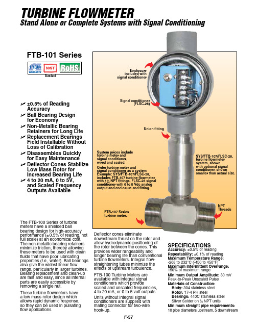
F-57The FTB-100 Series of turbine meters have a shielded ballbearing d esi gn for high-accuracy performance (±0.5% of reading, not full scale) at an economical cost. The non-metallic bearing retainers minimize friction, thereby allowing these meters to be used with clean fluids that have poor lubricatingproperties (i.e., water). Ball bearings also give the widest linear flowrange, particularly in larger turbines. Bearing replacement and clean-up are fast and easy, since all internal parts are easily accessible by removing a single nut.These turbine flowmeters have a low mass rotor design which allows rapid dynamic response, so they can be used in pulsating flow applications.TURBINE FLOWMETERStand Alone or Complete Systems with Signal ConditioningUnion fittingEnclosure with signal conditionerSYS/FTB-107/FLSC-28, turbine flowmeter system, shownwith optional signal conditioner, shownsmaller than actual size.U ±0.5% of Reading Accuracy U B all Bearing Design for Economy U N on-Metallic Bearing Retainers for Long Life U R eplacement Bearings Field Installable Without Loss of Calibration U D isassembles Quickly for Easy Maintenance U D eflector Cones Stabilize Low Mass Rotor for Increased Bearing Life U 4 to 20 mA, 0 to 5V, and Scaled Frequency Outputs AvailableFTB-101 SeriesSPECIFICATIONSAccuracy: ±0.5% of reading Repeatability: ±0.1% of reading Maximum Temperature Range: -268 to 232°C (-450 to 450°F)Maximum Intermittent Overrange: 150% of maximum rangeMinimum Output Amplitude: 30 mV Peak-to-Peak Unscaled Pulse Materials of Construction: Body: 304 stainless steel Rotor: 17-4 PH steelBearings: 440C stainless steel Silver Solder on 1⁄2 NPT unitsMinimum straight pipe requirements: 10 pipe diameters upstream, 5 downstreamsignal conditioner as a system Example: SYS/FTB-107/FLSC-28, includes FTB-107 turbine flowmeter NPT fittings, FLSC-28 signal conditioner with 0 to 5 Vdc analog output and enclosure and fitting.Signal conditioner(FLSC-28)Deflector cones eliminatedownstream thrust on the rotor and allow hydrodynamic positioning of the rotor between the cones. This provides wider rangeability andlonger bearing life than conventional turbine flowmeters. Integral flow-straightening tubes minimize the effects of upstream turbulence.FTB-100 Turbine Meters are available with integral signal conditioners which providescaled and unscaled frequencies, 4 to 20 mA, or 0 to 5 volt outputs Units without integral signal conditioners are supplied with mating connector for two-wire hook-up.F-58FEconomical Ball Bearing Design with NPT End FittingsComes complete with operator’s manual and 10-point NIST calibration certificate for water.Ordering Examples: FTB-101, 1⁄2 NPT turbine meter with standard NIST calibration for 1 cSt viscosity. FTB-106, 1 NPT turbine meter with NIST calibration for 5 cSt viscosity liquid.† Complete systems with signal conditioneravailable, consult sales.F-59OMEGA ® high accuracy integral signal conditioners are designed for direct mounting onto OMEGA FTB-100 and 200 Series turbine meters. The input circuitry of the signal conditioners has beendesigned to receive and condition low level turbine meter signalswhile rejecting unwanted noise and spurious signals. A signal threshold control is provided which allows the user to set the input sensitivity above the ambient noise level, thereby eliminating any false signal on the output. Signalconditioners are available that can provide 4 to 20 mA, 0 to 5V, and scaled frequency pulse outputs that run on unregulated power supplies. Other units which run off 115 Vac provide both an unscaled pulse output and a 0 to 5V or 4 to 20 mA output. A zero and a span potentiometer allow for simple field adjustment of the analog outputs from the signal conditioners.Maximum Input: 120V RMS Electrical Connections: Screw terminalsMaximum Lead Length: 305 m (1000') of 24 gage copper wire for pulse or mA; 30 m (100') for 0 to 5V output. Weight: 2.3 kg (5 lb)SPECIFICATIONSAccuracy: See “To Order” box Temperature Range: 0 to 70°C (32 to 158°F)Pulse Output: TTL/CMOS; open collector for FLSC-51BInput Frequency: 10-1000 Hz, 28 mV P-P; 1000-2500 Hz, 70 mV P-P. Can be used with any OMEGA ® Turbine MeterSignal conditioners are installed at no charge when purchased with turbine meter.Note: The use of explosion-proof heads does not imply that complete assembly is either explosion-proof or intrinsically safe. It is the user’s responsibility to determine the suitability of materials for a given installation.Comes complete with operator’s manual.Ordering Examples: SYS/FTB-101/FLSC-18B , turbine and signal conditioner system, SYS/FTB-201/FLSC-34, turbine and signal conditioner.INTEGRAL SIGNAL CONDITIONERSFor Frequency, Voltage, or Current OutputSignal Conditioner (Enclosure Mounted) OnlyU Up to 0.05% Accuracy U C hoose from Six Output TypesU CMOS/TTL Compatible U A djustable Low Level Signal Filter for Noise RejectionU E xplosion-Resistant Heads U F or FTB-100 and FTB-200 Turbine Flowmeters U I ntegral SignalConditioners Available for 4 to 20 mA, 0 to 5V, and Factored Pulse OutputsFLSC-18B SeriesFLSC-18B shown actual size.。
罗克韦尔自动化 Trusted 60 通道 24 Vdc 数字输入 FTA 非防爆 使用手册说明书

ICSTT-RM288C-EN-P (PD-T8805) Trusted Trusted 60 Channel 24 Vdc Digital Input FTA Non-IncendiveProduct OverviewThe Trusted® 60 Channel 24 Vdc Digital Input Field Termination Assembly (FTA) Non Incendive is designed to act as the main interface between a non-incendive field device in a hazardous area generating a digital signal and the Trusted Dual 24 Vdc Digital Input Module T8402.Features:•60 input channels per FTA.•Industry standard field device connections (2-wire).•Limited power for connection to non-incendive field wiring.•Standard DIN rail compatibility.•Simple installation and connection.•24 Vdc operation.Trusted ICSTT-RM288C-EN-PPage intentionally left blankPREFACEIn no event will Rockwell Automation be responsible or liable for indirect or consequential damages resulting from the use or application of this equipment. The examples given in this manual are included solely for illustrative purposes. Because of the many variables and requirements related to any particular installation, Rockwell Automation does not assume responsibility or reliability for actual use based on the examples and diagrams.No patent liability is assumed by Rockwell Automation, with respect to use of information, circuits, equipment, or software described in this manual.Allen-Bradley, LISTEN. THINK. SOLVE., Rockwell Automation, TechConnect, and Trusted are trademarks of Rockwell Automation, Inc.All trademarks are acknowledged.DISCLAIMERIt is not intended that the information in this publication covers every possible detail about the construction, operation, or maintenance of a control system installation. You should also refer to your own local (or supplied) system safety manual, installation and operator/maintenance manuals.REVISION AND UPDATING POLICYThis document is based on information available at the time of its publication. The document contents are subject to change from time to time. The latest versions of the manuals are available at the Rockwell Automation Literature Library under "Product Information" information "Critical Process Control & Safety Systems".TRUSTED RELEASEThis technical manual was updated for Trusted Release 4.0.LATEST PRODUCT INFORMATIONFor the latest information about this product review the Product Notifications and Technical Notes issued by technical support. Product Notifications and product support are available at the Rockwell Automation Support Centre atAt the Search Knowledgebase tab select the option "By Product" then scroll down and select the Trusted product.Some of the Answer ID’s in the Knowledge Base require a TechConnect℠ Support Contract. For more information about TechConnect Support Contract Access Level and Features, click on the following link:https:///app/answers/detail/a_id/50871This will get you to the login page where you must enter your login details.IMPORTANT A login is required to access the link. If you do not have an account then you can create one using the "Sign Up" link at the top right of the web page.DOCUMENTATION FEEDBACKYour comments help us to write better user documentation. If you discover an error, or have a suggestion on how to make this publication better, send your comment to our technical support group at SCOPEThis manual specifies the maintenance requirements and describes the procedures to assist troubleshooting and maintenance of a Trusted system. WHO SHOULD USE THIS MANUALThis manual is for plant maintenance personnel who are experienced in the operation and maintenance of electronic equipment and are trained to work with safety systems. SYMBOLSIn this manual we will use these notices to tell you about safety considerations.SHOCK HAZARD: Identifies an electrical shock hazard. If a warning label is fitted, it can be on or inside the equipment.WARNING: Identifies information about practices or circumstances that can cause an explosion in a hazardous environment, which can cause injury or death, property damage or economic loss.ATTENTION: Identifies information about practices or circumstances that can cause injury or death.CAUTION: Identifies information about practices or circumstances that can cause property damage or economic loss.BURN HAZARD: Identifies where a surface can reach dangerous temperatures. If a warning label is fitted, it can be on or inside the equipment.This symbol identifies items which must be thought about and put in place when designing and assembling a Trusted controller for use in a Safety Instrumented Function (SIF). It appears extensively in the Trusted Safety Manual.IMPORTANTIdentifies information that is critical for successful application and understanding of the product.NOTE Provides key information about the product or service.TIP Tips give helpful information about using or setting up the equipment.WARNINGS AND CAUTIONSWARNING: EXPLOSION RISKDo not connect or disconnect equipment while the circuit is live or unless the area is known to be free of ignitable concentrations or equivalentAVERTISSEMENT - RISQUE D’EXPLOSIONNe pas connecter ou déconnecter l’équipement alors qu’il est sous tension, sauf si l’environnement est exempt de concentrations inflammables ou équivalenteMAINTENANCEMaintenance must be carried out only by qualified personnel. Failure to follow these instructions may result in personal injury.CAUTION: RADIO FREQUENCY INTERFERENCEMost electronic equipment is influenced by Radio Frequency Interference. Caution should be exercised with regard to the use of portable communications equipment around such equipment. Signs should be posted in the vicinity of the equipment cautioning against the use of portable communications equipment.CAUTION:The module PCBs contains static sensitive components. Static handling precautions must be observed. DO NOT touch exposed connector pins or attempt to dismantle a module.ISSUE RECORDIssue Date Comments1 Aug 08 Initial Issue2 Jun 16 Rebranded and updated to incorporate IEEE standards with correction oftypographical errors and also standardise the Relative Humidity Rangeand Operating Temperature statements in the Specification Section.3 Jan 19 Update spec table. Added GA / pinout drawings.Updated to display Rockwell Automation publication numbers.Added trademarks statement.Page intentionally left blankTrusted 60 Channel 24 Vdc Digital Input FTA Non-Incendive Table of Contents Table of Contents1.Description (3)2.Installation (5)3.Associated Cable Selection (7)4.Assembly Pinout Connections (9)4.1. SK2 Connections (10)4.2. PL1 Connections (12)4.3. PL2 Connections (12)4.4. PL3 Connections (13)4.5. PL4 Connections (13)4.6. PL5 Connections (14)4.7. PL6 Connections (14)4.8. Table 7 PL6 ConnectionsPL7 Connections (15)4.9. PL8 Connections (16)4.10. PL9 Connections (16)4.11. PL10 Connections (17)4.12. PL11 Connections (17)4.13. PL12 Connections (18)5.Specifications (19)Table of Contents Trusted 60 Channel 24 Vdc Digital Input FTA Non-IncendivePage intentionally left blank1.DescriptionThe Trusted 60 Channel 24 Vdc Digital Input T8805 provides termination for a maximum of 60 input channels from various types of field devices which generate a digital input. Figure 1 below shows the configuration of a single channel.Figure 1 Single Channel SchematicThe field supply is derived from dual 24 Vdc feeds which are ‘commoned’ via diodes on the FTA. The supply is then fed to each channel.The supply voltage to the field is fed via the 220 Ω resistor. This effectively limits the current in the field loop allowing inputs from non-incendive field devices located in hazardous areas. The incoming signal (digital) from the field device is developed across the 5 kΩ resistor, then connected to the appropriate input circuit on the Input Module. Electrostatic discharge (ESD) transients are suppressed by a bi-directional Transient Voltage Suppresion diode (TVS) as shown. Line monitoring components (if required) provide the necessary thresholds used by the input module to detect the field loop/device status, i.e. open/short circuit, alarm etc. The connector linking the 60 channels on the input module to the FTA is terminated at SK2 which is a 96-way socket. The dual 24 Vdc power supplies are connected to the FTA via a single 4-way connector (PL1). Ten 12-way connectors are used for the field loops (PL2 to PL9, PL11 and PL12). PL10 is an auxiliary 2-way plug provided for power monitoring purposes (future use).Page intentionally left blank2.InstallationThe Trusted 60 Channel 24 Vdc Digital Input FTA T8805 Non-Incendive is designed to be mounted on either of the TS32 or TS35 DIN rails in the horizontal or vertical positions as required.Page intentionally left blank3.Associated Cable SelectionRefer to the product descriptions detailed below:ICSTT-RM311 (PD-TC200) Trusted I/O Companion Slot Cables ICSTT-RM314 (PD-TC600) Trusted I/O SmartSlot Cables 60-Channel ICSTT-RM315 (PD-TC700) Trusted I/O Companion Slot 60-ChannelPage intentionally left blank4.Assembly Pinout ConnectionsFigure 2 T8805 General assembly / pinout4.1.SK2 ConnectionsThe pin connections of SK2 are detailed below:PinRowA B C12 Not used Not used Not used3 CH_0_ABC CH_14_AB CH_28_BC4 CH_0_ABC CH_54_C CH_48_A5 CH_1_AB CH_15_AB CH_29_BC6 CH_41_C CH_55_C CH_49_A7 CH_2_AB CH_16_AB CH_30_BC8 CN_42_C CH_56_C CH_50_A9 0 V 0 V 0 V10 CH_3_AB CH_17_AB CH_31_BC11 CH_43_C CH_57_C CH_51_A12 CH_4_AB CH_18_AB CH_32_BC13 CH_44_C CH_58_C CH_52_A14 CH_5_AB CH_19_AB CH_33_BC15 CH_45_C CH_59_C CH_53_A16 CH_6_AB CH_20_AB CH_34_BC17 CH_46_C CH_60_C CH_54_A18 CH_7_AB CH_21_BC CH_35_BC19 CH_47_C CH_41_A CH_55_A20 0 V 0 V 0 VPinRowA B C21 CH_8-AB CH_22_BC CH_36_BC22 CH_48_C CH_42_A CH_56_A23 CH_9_AB CH_23_BC CH_37_BC24 CH_49_C CH_43_A CH_57_A25 CH_10_AB CH_24_BC CH_38_BC26 CH_50_C CH_44_A CH_58_A27 CH_11_AB CH_25_BC CH_39_BC28 CH_51_C CH_45_A CH_59_A29 CH_12_AB CH_26_BC CH_40_BC30 CH_52_C CH_46_A CH_60_A31 CH_13_AB CH_27_BC CH_61_ABC32 CH_53_C CH_47_A CH_61_ABCTable 1 SK2 ConnectionsNote: The pin assignments detailed above indicate the mapping of the input channel to the ‘slice’ on the Trusted Dual 24 Vdc Digital Input Module, e.g. channel 39 (pin 27, row C is mapped to ‘slices’ B and C.4.2.PL1 ConnectionsPin Service1 24 V-1 V2 0V3 0V4 24 V-2 VTable 2 PL1 Connections4.3.PL2 ConnectionsPin Service1 Channel 1 24 Vdc to field device2 Channel 1 return signal from field device3 Channel 2 24 Vdc to field device4 Channel 2 return signal from field device5 Channel 3 24 Vdc to field device6 Channel 3 return signal from field device7 Channel 4 24 Vdc to field device8 Channel 4 return signal from field device9 Channel 5 24 Vdc to field device10 Channel 5 return signal from field device11 Channel 6 24 Vdc to field device12 Channel 6 return signal from field deviceTable 3 PL2 Connections4.4.PL3 ConnectionsPin Service1 Channel 7 24 Vdc to field device2 Channel 7 return signal from field device3 Channel 8 24 Vdc to field device4 Channel 8 return signal from field device5 Channel 9 24 Vdc to field device6 Channel 9 return signal from field device7 Channel 10 24 Vdc to field device8 Channel 10 return signal from field device9 Channel 11 24 Vdc to field device10 Channel 11 return signal from field device11 Channel 12 24 Vdc to field device12 Channel 12 return signal from field deviceTable 4 PL3 Connections4.5.PL4 ConnectionsPin Service1 Channel 13 24 Vdc to field device2 Channel 13 return signal from field device3 Channel 14 24 Vdc to field device4 Channel 14 return signal from field device5 Channel 15 24 Vdc to field device6 Channel 15 return signal from field device7 Channel 16 24 Vdc to field devicePin Service8 Channel 16 return signal from field device9 Channel 17 24 Vdc to field device10 Channel 17 return signal from field device11 Channel 18 24 Vdc to field device12 Channel 18 return signal from field deviceTable 5 PL4 Connections4.6.PL5 ConnectionsPin Service1 Channel 19 24 Vdc to field device2 Channel 19 return signal from field device3 Channel 20 24 Vdc to field device4 Channel 20 return signal from field device5 Channel 21 24 Vdc to field device6 Channel 21 return signal from field device7 Channel 22 24 Vdc to field device8 Channel 22 return signal from field device9 Channel 23 24 Vdc to field device10 Channel 23 return signal from field device11 Channel 24 24 Vdc to field device12 Channel 24 return signal from field deviceTable 6 PL5 Connections4.7.PL6 ConnectionsPin Service1 Channel 25 24 Vdc to field device2 Channel 25 return signal from field device3 Channel 26 24 Vdc to field device4 Channel 26 return signal from field device5 Channel 27 24 Vdc to field device6 Channel 27 return signal from field device7 Channel 28 24 Vdc to field device8 Channel 28 return signal from field device9 Channel 29 24 Vdc to field device10 Channel 29 return signal from field device11 Channel 30 24 Vdc to field device12 Channel 30 return signal from field device 4.8.Table 7 PL6 ConnectionsPL7 ConnectionsPin Service1 Channel 31 24 Vdc to field device2 Channel 31 return signal from field device3 Channel 32 24 Vdc to field device4 Channel 32 return signal from field device5 Channel 33 24 Vdc to field device6 Channel 33 return signal from field device7 Channel 3424 Vdc to field device8 Channel 34 return signal from field device9 Channel 35 24 Vdc to field device10 Channel 35 return signal from field devicePin Service11 Channel 36 24 Vdc to field device12 Channel 36 return signal from field deviceTable 8 PL7 Connections4.9.PL8 ConnectionsPin Service1 Channel 37 24 Vdc to field device2 Channel 37 return signal from field device3 Channel 38 24 Vdc to field device4 Channel 38 return signal from field device5 Channel 39 24 Vdc to field device6 Channel 39 return signal from field device7 Channel 40 24 Vdc to field device8 Channel 40 return signal from field device9 Channel 41 24 Vdc to field device10 Channel 41 return signal from field device11 Channel 42 24 Vdc to field device12 Channel 42 return signal from field deviceTable 9 PL8 Connections4.10.PL9 ConnectionsPin Service1 Channel 43 24 Vdc to field device2 Channel 43 return signal from field device3 Channel 44 24 Vdc to field device4 Channel 44 return signal from field device5 Channel 45 24 Vdc to field device6 Channel 45 return signal from field device7 Channel 46 24 Vdc to field device8 Channel 46 return signal from field device9 Channel 47 24 Vdc to field device10 Channel 47 return signal from field device11 Channel 48 24 Vdc to field device12 Channel 48 return signal from field deviceTable 10 PL9 Connections4.11.PL10 ConnectionsPin Service1 Channel 02 Channel 61Table 11 PL10 Connections4.12.PL11 ConnectionsPin Service1 Channel 49 24 Vdc to field device2 Channel 49 return signal from field device3 Channel 50 24 Vdc to field device4 Channel 50 return signal from field device5 Channel 51 24 Vdc to field device6 Channel 51 return signal from field device7 Channel 52 24 Vdc to field devicePin Service8 Channel 52 return signal from field device9 Channel 53 24 Vdc to field device10 Channel 53 return signal from field device11 Channel 54 24 Vdc to field device12 Channel 54 return signal from field deviceTable 12 PL11 Connections4.13.PL12 ConnectionsPin Service1 Channel 55 24 Vdc to field device2 Channel 55 return signal from field device3 Channel 56 24 Vdc to field device4 Channel 56 return signal from field device5 Channel 57 24 Vdc to field device6 Channel 57 return signal from field device7 Channel 58 24 Vdc to field device8 Channel 58 return signal from field device9 Channel 59 24 Vdc to field device10 Channel 59 return signal from field device11 Channel 60 24 Vdc to field device12 Channel 60 return signal from field deviceTable 13 PL12 Connections5.SpecificationsField Supply 18 Vdc to 32 VdcPower Dissipation 0.2 W / channel; 12 W maximum IsolationField CommonField circuits to chassis ground (Slider clamp / DIN rail) 50 V Reinforced (continuous) (1) 250 V Basic (fault) (2)[Type tested at 2436 Vdc for 60 s].50 V Reinforced (continuous) (1) 250 V Basic (fault) (2)[Type tested at 2436 Vdc for 60 s].Fusing N/AMaximum Normal Output Current I sc(Field Supply)6.1 mA / channel; 366 mA totalMaximum Normal Output Voltage V oc(Field Supply)32 V as voltage range aboveMaximum External Capacitance C a 5 μF for methane0.3 μF for groups A and Bin accordance with AANSI/ISA 12.12.01-2000Maximum External Inductance L a100 mH for methane or group Bin accordance with AANSI/ISA 12.12.01-2000 Operating Temperature 0 °C to +60 °C(+32 °F to +140 °F)Storage Temperature -25 °C to +70 °C(-13 °F to +158 °F) Relative Humidity - Operating and Storage 10 % – 95 %, non-condensing Environmental Specifications Refer to Document ICSTT-TD003 DimensionsHeight 110 mm (4.44 in)Width 455 mm (17.9 in)Depth68 mm (2.67 in)(including mounting rail andconnectors)Weight 76 2g (1.68 lb)Note 1) 50 Vrms Secondary circuit derived from Mains, OVC II up to 300V.Note 2) 250 Vrms Mains circuit, OVC II up to 300V. Exposure to voltages at these levels shall be temporally constrained consistent with the system MTTR.。
FTB2000系列流量传感器产品说明书

Wetted Materials Accuracy: ±3% of reading Repeatability: 0.5% FS Body: Nylon 12 Turbine: Nylon 12 composite Bearings: PTFE/15% graphite Operating Pressure: 200 psig Operating Temperature: -20 to 100°C (-4 to 212°F ) Viscosity: 32 to 81 SSU (0.8 to 16 centistokes) Filter: <50 microns Input Power: 5 to 24 Vdc @ 8 mA Output: NPN sinking open collector @ 50 mA max (1 to 2.2 kΩ pull-up resistor required) (Hz output) Electrical Connection: Spade terminals 2.8/6.3 x 0.8 mm (0.110/.248 x 0.031") Inlet/Outlet Ports: 3⁄8 MNPT
ECONOMICAL FLOW RATE SENSORS
FTB2000 Series
$86
FTB2001, $86, shown larger than actual size.
ߜ Low Cost ߜ High Accuracy
(±3% of Reading) ߜ tes of 0.13 to 7.9 GPM ߜ FDA-Approved Materials ߜ Lightweight Plastic Design Permits Mounting in Any Position
FTB 系列仪表以太网测试指南

FTB-1 880 系列仪表使用指南FTB-880系列测试套件提供包括:Ether SAM, RFC-2544、Ether BERT、流量生成与监测、FC BERT, CPRI/OBSAI, 第二端口环回,以及连通性测试(VLAN, MPLS, QOS);也提供包括自动发现远程测试仪、智能环回、穿通测试、ping、路由跟踪等功能.使现场技术人员可轻松、迅速地进行从10 Mbit/s到10 Gbit/s的以太网服务开通、验证和故障诊断。
测试应用:一.EtherSAM:二:RFC-2544(单端测试):三:EtherSAM/ RFC-2544(双向测试):四:Ether BERT:五:流量生成与监测六:穿通模式七:FC BERT:八:CPRI/OBSAI BERT:九:第二端口LPBK环回:十:智能环回十一以太网工具:PING、路由跟踪、电缆测试(仅适用于电口)十二配置/保存、打开以及导入/导出测试报告测试端口:测试界面:1.设置:根据测试场景选择具体的测试应用;针对测试应用配置测试的接口,全局……参数;2.状态栏:在仪表最底端的状态栏会显示当前仪表的配置信息;3.控制栏:在仪表的右变是控制栏,包括启动测试的开始按钮,保存测试配置文件,加载测试配置文件,保存测试报告,查找远端设备,LPBK工具……控制工具都在控制栏里;4.结果:测试开始后,可以到结果界面查看测试结果;接口配置(所有测试工具接口测试都是通用的)1.选择以太网测试项或者以太网工具项。
2.选择接口,配置端口/网络层参数,如果应用了光口,可查看SFP/SFP+参数。
测试应用:一.EtherSAM:1.在测试应用选择EtherSAM(Y.1564);2.根据具体的测试场景,分别配置接口,全局,业务,阶梯选项卡:接口:接口配置主要包括指定测试使用的端口,配置端口类型,双工模式,MAC地址,IP地址等配置选项(截图见接口配置)全局:选择测试方式为单向测试(双向测试单独列了出来,见后文),另外可以配置子测试项;业务:主要配置测试所使用的信息流,包括业务信息流的数量,每一条流的类型,SLA阈值,是否带VLAN,MPLS……阶梯:配置测试流程;3.配置完成后,点击开始即可测试。
FTB-5240-S 带内OSNR简要操作步骤

EXFO FTB-5240S OSNR 测试测试简要简要简要操作步骤操作步骤1. 系统准备系统准备和测试基本流程和测试基本流程安装好相关模块,并根据仪器的端口选择合适的跳线,连接好设备,每次连接跳线之前,都仔细检查光纤端面,保证清洁。
如有必要,按正确方法取下EUI 后,用棉签仔细清洁内部。
测试基本流程如下:启动OSA 模块→设置取样参数→设置分析参数→开始测试→保存测试结果2.测试具体方法及步骤1)在FTB-500平台上启动Toolbox 软件,如图1:Fig 1点击OSA WDM ,启动FTB-5240S 模块的WDM 程序2)设置取样参数Fig 2a)取样类型测试40Gbps系统:选“带内(In band)”或i In-band取样计数Count设置:对于100GHz(通道宽度)系统,设置为200;50GHz系统设一般为500;50GHz+多ROADM的系统,则一般设为1000选择i In-band则不需要设置计数值测试10Gbps系统:选“单次”或“平均”,平均次数酌情而定,一般4-10次皆可。
b)设置取样的波长范围,可通过移动如图2所示的两个游标实现,或在起止波长框内手动输入波长数字。
3)设置分析参数点击主菜单的Analysis Setup,将弹出分析参数设置窗口,如图3Fig 3 在General 选项卡内a) 根据被测系统,设置channel 的宽度,50GHz 、100GHz 等。
b) Noise for OSNR ,这一项根据前面的取样类型来设定。
如果前面选择了“带内”,则这里设为“In Band ”(100GHz 间隔或50GHz 间隔的点对点系统);若被测系统是50GHz 并有ROADM ,(或者有除梳状滤波器之外其它的滤波器存在) 则该项选择“In Band narrow filter ” 如果前面选择了i In-band ,这里无需设置。
如果前面选择了“单次”或“平均”,则这里设为“IEC ”固定插值法c) Signal power 设置为“Integrated Signal Power ”注意:Channels 选项卡:此设置为高级分析用,如果此位置Channel 定义不对,测试结果将不准确。
FTB-810快速使用指南
FTB-810快速人门作者:江怀目录:∙仪表结构---------------------------------------------------------------------1-3 1.FTB-1-810结构介绍----------------------------------------------12.FTB-1平台结构及按键功能介绍-----------------------------1-23.FTB-810结构介绍-------------------------------------------------3∙仪表配置与测试-----------------------------------------------------------3-14 1.仪表启动与测试配置--------------------------------------------3-72.测试执行与结果--------------------------------------------------8-93.生成测试报告-----------------------------------------------------10-114.快速测试------------------------------------------------------------11-12 5.误码/告警----------------------------------------------------------12-136.RDT/复用段/指针/开销等功能测试------------------------13-14∙远程控制--------------------------------------------------------------------15 1.Telnet远程登陆--------------------------------------------------152.VNC远程控制-----------------------------------------------------15 ∙选件激活--------------------------------------------------------------------15-16 ∙软件升级,安装与激活------------------------------------------------16-17 ∙产品维护须知-------------------------------------------------------------17-18仪表结构:FTB-1/810仪表由FTB-1平台和FTB-810模块两部分组成,平台主要是提供基于不同应用模块的公共功能部分,模块则提供具体的测试功能。
一体式24V供电二线制超声波液位计说明书

温馨提示:安装调试前,请仔细阅读用户手册!!用户手册量程:0、5-5米额定电压: DC24V江苏美安特自动化仪表有限公司二线制超声波液位计超声波液位计……………………………………………………………………保修政策:●用户在维修时请出示保修卡。
在保修期内因正常使用出现的故障,可凭保修卡享受规定的免费保修。
●保修期限:本公司产品保修期由验收日期起算十二个月内。
以下情况不在免费保修范围内:●产品或其部件已超出免费保修期。
●因使用环境不符合产品使用要求而导致的硬件故障。
●因不良的电源环境或异物进入设备所引起的故障或损坏。
●由于未能按使用操作手册上所写的使用方法与注意事项进行操作而造成的故障。
●由于不可抵抗力如:雷电、水火灾等自然因素而造成的故障。
擅自拆机修理或越权改装或滥用造成的故障或损坏。
限制说明:●请用户妥善保存保修卡作为保修凭证,遗失不补。
本保修卡解释权限归本公司所有,本公司有权对本卡内容进行修改,恕不事先通知。
7超声波液位计目录1概述...................................................................................................、1 2 技术指标 (1)3仪表安装…………………………………………………………………………………、23、1仪表外形尺寸 (2)3、2仪表接线 (2)3、3安装参数含义 (3)3、4仪表安装原则 (3)3、5安装注意事项 (4)4仪表调试.............................................................................................、4 4、1键盘说明.....................................................................、......、 (4)4、2 参数的设置........................................................................、......、 (4)4、2、1 P01(液位标定) (4)4、2、2 P02、P03(输出电流设置) (5)4、2、3 P05(显示模式选择) (5)4、2、4 P06(探头高度设置) (5)4、2、5 P07() (5)4、2、6 P08(电流测试) (5)4、2、7 P09() (6)超声波液位计保修卡回执 (7)型超声波液位计1、概述衷心感谢您选购本公司超声波液位计!本仪表包含多项专利技术,具有安全、清洁、精度高、寿命长、稳定可靠、安装维护方便等特点,适用酸、碱、盐、防腐、高温等各种领域。
超滤操作说明书-百世10吨(含电气)

安全使用注意事项出于本装置的性能及使用安全性考虑,操作人员必须遵守以下使用原则:1.操作人员必须具备机械、电气以及化学的基本知识和常识。
2.操作人员必须熟悉本装置的性能、原理及使用方法等。
未经教育的其他人员禁止操作。
3.定期进行点检。
4.点检时发现设备有破损、漏水等不良现象,必须及时进行修复。
5.在进行点检或修理时,必须注意防止误动作。
6.药品的添加及储存时应注意安全,部分药品具有腐蚀性。
第一章:概要非常感谢百世环保科技开发XX对XX英特工业水处理工程XX的信任!请您认真的阅读本使用说明书,这将有助于您更好地了解及使用我们为贵公司提供的产品。
请妥善保存此使用说明书,以备查阅。
1.1简介本使用说明书详细阐述了为贵公司提供的超滤设备的全部操作方法及控制原理。
装置中所属的设备、仪表,如:泵类、减压阀、压力表、流量计、液位计等都附有各自设备、仪表的使用维护说明书及产品简介等资料,请参考阅读,并熟悉操作方法。
操作人员在操作本装置前务必要对本操作说明书及各设备、仪表的技术资料给予详细阅读并充分理解;要严格按照本操作说明书规X的内容执行系统的操作与维护,任何违反本操作说明书要求的操作都可能会造成系统的运行故障、设备损坏等问题,甚至会引发人身伤害事故。
1.2 处理工艺概要本处理装置包括滤芯过滤和膜分离等处理工艺。
1.2.1滤芯过滤处理工艺根据百世环保科技开发XX的用水要求以及原水的水质状况,设计该装置。
在原水进入超滤系统前,设置了保安过滤器,将可能造成膜损坏的、较大的机械性杂质过滤掉。
1.2.2膜分离处理工艺经保安过滤器处理后的水进入超滤膜,能有效的降低原水的浊度及细菌。
1.3处理设备概要①预处理设备┅┅保安过滤器。
②超滤设备┅┅超滤膜单元。
③清洗系统┅┅清洗设备。
④加药系统┅┅次氯酸钠加药设备。
第二章:处理系统原理2.1预处理2.1.1保安过滤器为防治原水中有异物进入微滤膜系统,对膜造成损坏,在原水进入膜系统之前,设置了过滤精度为10μ的保安过滤器,将可能造成膜损坏的、较大的机械性质过杂滤掉,保证了微滤的进水要求。
2光4电交换机使用说明书
2光4电交换机使用说明书型号:FT2400FE天津滨海新区三格电子科技有限公司一、概述本产品为带光口的交换机,在传统的五类六类线网络只有一百米的数据传输覆盖区域的基础上,本产品所带的光口可以将数据通过光口传输,以将数据传输范围扩展到千米的级别,最大的覆盖范围为25千米,具有一般的只有电口的交换机不具有的远距数据传输的优良特性。
短距离和长距离的数据传输范围的组合选择,使网络数据的传输的范围大小配置更为灵活。
还可与本公司的双纤双向100M光纤收发器配合使用,组网更为方便。
二、规格与特性标准:IEEE802.3az EEE,IEEE802.3,IEEE802.3u, IEEE802.3x100Base-FX,100Base-TX接口:电口,RJ45;光口,SC。
传输速率:光口155Mbps;电口10/100Mbps自适应。
光口:全双工距离:25KM电口:全双工/半双工网线:五类双绞线。
光纤:SC口,单模,双纤,1310nm。
电源:直流5V,1A。
附带节能方式:无连接时将自动进入省电模式,有连接但无数据会自动进入节电模式。
环境温度:-20---70°C存储温度:-65---150°C湿度:5%---90%三、安装方法1、连接光纤,光纤需要交叉连接,交换机光口A的RX接收发器(可以是交换机光口)B的TX,交换机光口A的TX接收发器(可以是交换机光口)B的RX。
2、接网线,网线可以是直连型,也可以是交叉型,电口可以自适应两种网线,可与其他的交换机相接。
注意:网线不能和其他的交换机构成环路。
3、上电。
四、LED指示灯Pow/off:板卡工作电源和耗能指示灯,在正常工作状态下灯亮,在强制掉电下灯灭;Fiber0、Fiber1:灯亮且长周期性闪烁表示光口有连接且连接成功,灯灭表示无连接或者连接失败;短周期性闪烁表示有数据正在传输。
TP0、TP1、TP2、TP3:灯亮且长周期性闪烁表示电口连接且连接成功,灯灭表示无连接或者连接失败;短周期性闪烁表示有数据正在传输。
博达产品用户手册
FEC-10/100S自适应以太网光纤收发器用户手册一、概述FEC-10/100系列以太网光纤收发器通过把原来在双绞线上传输的电信号转换为在光纤上传输的光信号,延伸了以太网的连接距离。
FEC-10/100系列光纤收发器的光接口满足IEEE802.3u 100BASE-FX标准,电接口满足IEEE802.3 10BASE-T和IEEE802.3u 100BASE-TX,可以灵活地满足局域网的用户和网络系统集成商的组网需求。
二、产品特性单模的光纤连接单模传输距离可达25公里光接口满足IEEE802.3u 100BASE-FX标准电接口满足IEEE802.3 10BASE-T、IEEE802.3u 100BASE-TX全双工和半双工模式自适应开关切换RJ-45平行接口(Straight)和交叉接口(Cross)完备的LED状态指示三、应用说明1、典型应用1图1为光纤收发器典型应用1的连接示意图。
一台配备有10/100BASE-TX接口的网络设备A通过双绞线连接到光纤收发器的RJ-45接口上,另一台网络设备B配备有100BASE-FX接口,它通过光纤连接到光纤收发器的100BASE-FX 接口,即可实现配有10/100BASE-TX接口的网络设备与配有100BASE-FX接口的网络设备互连。
网络设备A、B可以是以太网服务器、工作站、路由器、交换机、集线器等。
双绞线单/多模光纤接口100BASE-FX接口图1、典型应用12、典型应用2在图2中,网络设备A 与网络设备B 都配有10/100BASE-TX 接口,通过两台光纤收发器可实现网络设备A 与网络设备B 之间的远距离互连。
双绞线 单/多模光纤双绞线100BASE-FX 接口图2、典型应用210/100BASE-TX 接口 接口四、外观说明1、指示灯★ PWR :电源指示★ TXD :该灯亮表示RJ-45电接口已连接好,闪烁表示电口数据收发★ FXD :该灯亮表示光纤接口已连接好,闪烁表示光口数据收发★ 100:该灯亮表示电接口工作在100BASE-TX 状态,不亮表示工作在10BASE-T 状态2、MDI / MDI-X :RJ-45接口转换开关★ 置于“MDI-X ”位置:此时RJ-45为交叉接口(Cross ), 可与其它设备的平行接口(Straight )相连。
百特数显表操作方法精编版

百特数显表操作方法精编版百特智能数显表说明书工作状态下按SE T显示LOCY→按SET输入密码18→按SE T显示RAN9→按SE T通过△▽选择分度号→按SET显示Poin设置小数点→按SET显示r9.00设置量程下限→按SET显示r9.FS设置量程上限工作状态下按SET→通过△▽选择COrr按SET显示old.1→按SET 通过△▽修正温度值参数设定说明:Locy:菜单上锁操作入口;按SET键确认;按△▽键退出;开锁密码为18Ran9.:分度号和量程设置入口;按SET键确认;按△▽键退出0-10/…/y:分度号设置;按△▽键设置;按SET确认PoIn:小数点位置设置;按△▽键设置;按SET确认R9.00:量程零点设置;按△▽键设置;按SET确认R9.FS:量程满度设置;按△▽键设置;按SET确认Corr:量程迁移和滤波时间设置菜单入口;按SET键确认;按△▽键取消Old.1:修正温度值;按△▽键设置;按SET确认按键说明:△:变更参数设定时,用于增加数值SET:参数设定确认键▽:变更参数设定时,用于减少数值常见故障处理:仪表通电不亮:供电电源未接入,正确接入仪表电源;接触不良,取出表芯确认弹片接触是否良好。
LED屏显示:broy分度号选择错,选择与输入信号相符的分度号;输入信号太大,调节与输入信号保证在仪表范围内;信号短线,正确接入信号线。
H.oFL.分度号选择错,选择与输入信号相符的分度号;输入信号太大,调节与输入信号保证在仪表范围内;仪表标定错误,选择正确标定信号重新标定。
L.Ofl.: 选择与输入信号相符的分度号;输入信号太小,调节与输入信号保证在仪表范围内;仪表标定错误,选择正确标定信号重新标定昌辉SWP系列智能仪表说明书控制方式:1、正确的接线仪表卡入表盘后,请参照仪表随机接线图接妥输入、输入及电源线,并请确认无误。
2、仪表的上电本仪表与电源开关,接入电源即进入工作状态。
3、仪表设备号及版本号的显示仪表在投入电源后,可立即确认仪表设备号及版本号。
- 1、下载文档前请自行甄别文档内容的完整性,平台不提供额外的编辑、内容补充、找答案等附加服务。
- 2、"仅部分预览"的文档,不可在线预览部分如存在完整性等问题,可反馈申请退款(可完整预览的文档不适用该条件!)。
- 3、如文档侵犯您的权益,请联系客服反馈,我们会尽快为您处理(人工客服工作时间:9:00-18:30)。
加 拿 大 EXFO 公 司
EXFO INC.
目录
一.概览 二. DWDM 常用维护测试项目 三.漂移模式下的测试 四. OTU 板(波长转换器)的测试 五.合波器(OMU)、分波器(ODU)的测试 六.EDFA(光放大器)测试 七.软件的升级
EXFO EXFO
深北圳京代代表表处处::深北圳京市市福东田城区区金北田三路环4东0路28
51). 在如主何界生面成,报按告“?文件”
EXFO EXFO
深北圳京代代表表处处::深北圳京市市福东田城区区金北田三路环4东0路28
3号6 ,号经环贸球中贸心易中27心111室207邮室编邮:编51:8013050013
加 拿 大 EXFO 公 司
EXFO INC.
2)按“报告”
3)会弹出如下存储窗口,输入文件名,选择保存类型(.html 或.txt 格式)
3号6 ,号经环贸球中贸心易中27心111室207邮室编邮:编51:8013050013
一.概览
1. DWDM 系统接口参考图:
加 拿 大 EXFO 公 司
EXFO INC.
上述 DWDM 系统接口图中各参考点的定义如下: S 点为发送端的 OTU 输入光连接器前的光纤上的参考点; S1…Sn 点分别为通道 1…n 的发送端的 OTU 和作再生器用的 OTU 输出光连接器处的光纤上的参考点; RM1…RMn 点分别为通道 1…n 在合波器输入光连接器前的光纤上的参考点; S”点为合波器输出光连接器处的光纤上的参考点; MPI-R”为光放大器输入光连接器前的光纤上的参考点; MPI-S 点为光放大器输出光连接器后的光纤上的参考点; MPI-R 点为前置放大器输入光连接器前的光纤上的参考点; MPI-S”点为前置放大器输出光连接器后的光纤上的参考点; R”点为分波器输入光连接器处的光纤上的参考点; SD1…SDn 点为通道 1…n 在分波器输出光连接器处的参考点; RR1点…为Rn接点收为端接O收TU端输的出O光TU连和接作器再处生的器参用考的点O。TU 输入光连接器处的参考点;
EXFO EXFO
深北圳京代代表表处处::深北圳京市市福东田城区区金北田三路环4东0路28
3号6 ,号经环贸球中贸心易中27心111室207邮室编邮:编51:8013050013
加 拿 大 EXFO 公 司
EXFO INC.
61). 图查形看选W项D卡M下测的试界结面果如下图:
EXFO EXFO
深北圳京代代表表处处::深北圳京市市福东田城区区金北田三路环4东0路28
以上各测试应用的具体操作,各项设置、相关参数的意义,请参见下面的章 节。
EXFO EXFO
深北圳京代代表表处处::深北圳京市市福东田城区区金北田三路环4东0路28
3号6 ,号经环贸球中贸心易中27心111室207邮室编邮:编51:8013050013
加 拿 大 EXFO 公 司
EXFO INC.
二.15234..... D通通x信噪xW道道噪声dB积中比功D光(分心率M谱O功波宽S率长N常度/R频)用率及维偏护移 测试项目: 3同124.... 时平扫信平给均描号均出信功范系OS号率围统N功平内总R总率坦的功度参率数
加 拿 大 EXFO 公 司
EXFO INC.
六.EDFA 模式下的测量
加 拿 大 EXFO 公 司
EXFO INC.
4. 文件的保存,方法同 WDM 模式 5.报告的生成,方法同 WDM 模式
EXFO EXFO
深北圳京代代表表处处::深北圳京市市福东田城区区金北田三路环4东0路28
3号6 ,号经环贸球中贸心易中27心111室207邮室编邮:编51:8013050013
五.光谱透过率模式下的测量
进入光谱透过率模式的方法,在主界面,按“模式”→光谱透过率 1点. 分击“析分参析数的设置设”置,跟 WDM 模式下的分析设置基本一致 具2. 取体样方参法数同的W设DM置模式 测输试入端连接:示意图:
加 拿 大 EXFO 公 司
EXFO INC.
以上也可以是其他光源或 WDM 设备发光,即光谱仪在合波器或分波器的输入端。
3号6 ,号经环贸球中贸心易中27心111室207邮室编邮:编51:8013050013
2)“结果”选项卡
加 拿 大 EXFO 公 司
EXFO INC.
3能)够标查记看线各选个项通卡道的中心波长、功率、OSNR、噪声、带宽等数据
率4这)差里“、用通积户道分可结功以果率移”。动选标项记卡线,显示标记线所在位置的中心波长、对应功率以及两条标记线之间的波长差、功
2. WDM 系统常用维护测试中,需要用光谱分析仪测试的主要是: 中心频率(波长)及偏移、光信噪比、通道功率,这几个指标利用光谱仪的 “WDM”模式测试。
EXFO EXFO
深北圳京代代表表处处::深北圳京市市福东田城区区金北田三路环4东0路28
3号6 ,号经环贸球中贸心易中27心111室207邮室编邮:编51:8013050013
按“输入”然后按“开始”即可开始取样测试 完输成出后端改:变光谱仪的接入位置,如下图:
FLS-2300B
FTB-5ห้องสมุดไป่ตู้40
光谱仪在合波器或分波器的输出端,按“输出”然后按“开始”即可开始取样测试。
EXFO EXFO
深北圳京代代表表处处::深北圳京市市福东田城区区金北田三路环4东0路28
3号6 ,号经环贸球中贸心易中27心111室207邮室编邮:编51:8013050013
EXFO EXFO
深北圳京代代表表处处::深北圳京市市福东田城区区金北田三路环4东0路28
3号6 ,号经环贸球中贸心易中27心111室207邮室编邮:编51:8013050013
加 拿 大 EXFO 公 司
EXFO INC.
的延采持漂文如.迟样续移件果os::时文夹选aw进漂间件位择dm:行移名置了文漂::“第测件保保保移一量。存存存测次时重文漂历量取各大史件移的样次事取曲时文总的件线样使件持延是到起用的续迟指子始的位时时:文的文置间间给,件间件定应夹隔名通”用时道,程间上漂序某移会个测等值量待超过相过程应了中的阈发时值生间;重后给大开定事始通件取道时样上取没样有可信保号存功为率单独 4. 开始测试: 按主界面的“开始”即可 5. 测试文件的保存同 WDM 模式
加 拿 大 EXFO 公 司
EXFO INC.
EXFO FTB-5240S/5240BP 光谱仪使用指南 (FTB-200 V2 平台)
EXFO 公司 2010 年 11 月
EXFO EXFO
深北圳京代代表表处处::深北圳京市市福东田城区区金北田三路环4东0路28
3号6 ,号经环贸球中贸心易中27心111室207邮室编邮:编51:8013050013
操1L主.或作选界其指择面它南波波设:长长置范范起围围始)波长和终止波长 可以输入数字,也可以选择某个波段 如 1 图(根据系统情况选择 C 或
2主.分界析面参数分的析设设置置: 常规 如下图:
EXFO EXFO
深北圳京代代表表处处::深北圳京市市福东田城区区金北田三路环4东0路28
3号6 ,号经环贸球中贸心易中27心111室207邮室编邮:编51:8013050013
4主. 开界始面测试开,始记录结果随即得到如下结果:
EXFO EXFO
深北圳京代代表表处处::深北圳京市市福东田城区区金北田三路环4东0路28
3号6 ,号经环贸球中贸心易中27心111室207邮室编邮:编51:8013050013
加 拿 大 EXFO 公 司
EXFO INC.
4主. 界如面何存文储件数据另?存为 在弹出的窗口输入文件名,按保存即可。如果需要,可以更改保存路径
加 拿 大 EXFO 公 司
EXFO INC.
3. OUT 板(波长转换器)的主要测试指标:输出功率、边模抑制比、带宽, 利用光谱仪的“DFB”模式测试。 4. 合波器 (OMU)、分波器(ODU)的主要测试指标:插损、插损差异、通道隔 离度,利用光谱仪的“光谱透过率”模式测试。 5. EDFA(光放大器)的主要测试指标:输入功率、输出功率、通道增益, 利用光谱仪的“EDFA”模式测试。 6. 漂移模式主要用于连续一段时间监控系统,其测试指标和参数设置,同 WDM 模式相似,测试波长、频偏、信噪比、通道功率指标,但可以设置在 一定延迟后,开始取样,隔一定时间取样一次,一共持续多长时间。 其中 DFB、光谱透过率、EDFA、Drift 漂移三个模式,是选件,如果没有选 购,可以略过。
EXFO EXFO
深北圳京代代表表处处::深北圳京市市福东田城区区金北田三路环4东0路28
3号6 ,号经环贸球中贸心易中27心111室207邮室编邮:编51:8013050013
加 拿 大 EXFO 公 司
EXFO INC.
7)功率偏移:表示应用到功率的偏移量,通常设为 0 8)带宽(峰值下):计算带宽时所使用的功率电平(相对于通道峰值功率),通常设为 20dB 按“确定”保存设置。 列3W. D)设M置单平实带模取次均时内式样::::下参进根光对有数行据谱于一用测内4 种次户量置取光输将偏样谱入连振类测的续控型量扫进制:描行的单次直模次数到块、,进用平用行户均不光按、“同谱实停的测时止偏量和,”振带取态内平进(均行带值一内系仅列限扫于描F,T从B-而52实40现S-PO和SNFRT的B-I5n2-4B0aBnPd系测试 在主界面的“数据采集”选项卡的“类型”下拉菜单里选择取样类型,如下图:
加 拿 大 EXFO 公 司
EXFO INC.
1如)系通统道为宽5度0G和HOz 通SN道R间间隔距,: 根输据入系O统SN情R况间选隔择为,2如5G系H统z。为 100GHz 通道间隔,输入 OSNR 间隔为 50GHz; 2积峰的总)。分值通.信信信道号号号功功功功率率:率率表计::示算表表通:示示选道此通择宽通道度积道内内分的的包信通最含号道大的功界功功率限率率、,之值峰但间之值它的和信与功,号光率包功谱值括率上之噪或测和声总得减。通的去道峰相功值同率略边有界不内的同噪,声它是减去估计的噪声后得到 )3 OSNR 噪声: 根据所测量系统及 OSA 具体型号,选择 IEC、带内、带内窄带滤波器 4)峰值探测数值:表示可视为信号的波峰的最低功率电平,一般设为-45dBm )5 OSNR RBW:表示选定 OSNR 的分辨率带宽,通常设为 0.10 nm 6)波长偏移:表示应用到波长的偏移量,通常设为 0
