6 ADAMS_CAR模块详细实例教程(转向篇)
ADAMS CAR模块介绍

1.2.4驾驶员模块Driver
ADAMS/Driver 是一个可选模块,是 在德国的 IPG-Driver 基础上经过二次 开发形成的成熟产品。利用该模块, 可以提高车辆动力学仿真的真实感, 特别使用与装备有各种正负反馈的智 能系统(例如:ABS、4WS、CCS)的汽 车。
1.2.5 动力传动模块Driveline
1.2
ADAMS/CAR软件相关模块
SD EDM CSM Driver
3D Road Engine powered by FEV Durability Solver Controls
Driveline
CAR
MACHANISM/Pro
Exchange
1.2.1悬架设计软件包SD
Suspension Design 中包括以特征 参数(前束、定位参数、速度)表示 的悬架模型。通过这些特征参数,设 计师可以快速确定在任意载荷和轮胎 下的轮心位置和方向,在此基础上, 快速建立包括橡胶衬套在内的柔体悬 架模型。它采用的是全参数的面板建摸方式。借助悬架模 块,设计师可以提出原始的悬架设计方案。在此基础上, 通过调整悬架参数就可以快速确定满足理想悬架特性的悬 架方案。
立体平画法 曲面的多边形表示方法 和着色文件
波前文件 FEA载荷 储存模型几何形状和运动数据的输出文件 输出有关节点载荷的变化情况,供进一步的有 限元分析
电子数据表 以电子数据表格式输出的仿真分析结果
第4章 ADAMS/CAR在汽车操纵稳 定性中的应用
4.1 稳态转向试验仿真
2.2 仿真过程
Build
Test
Simulate &Review
PostProcessor
转向机建模(adams.car)
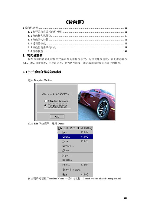
《转向篇》6转向机建模 (185)6.1打开系统自带转向机模板 (185)6.2修改转向机硬点 (187)6.3修改助力特性 (188)6.4通讯器修改 (188)6.5修改齿轮齿条传动比 (189)6.6保存模型 (191)6.转向机建模轿车常用的转向机结构形式基本都是齿轮齿条式,为加快建模速度,在此推荐修改Adams/Car自带模板,主要是硬点、助力特性曲线、通讯器和齿轮齿条传动比的修改。
6.1打开系统自带转向机模板Template Builder进入在出现的对话框Template Name一栏右击鼠标,Search><acar_shared>/template.tbl185在出现的文件夹里选择rack_pinion_steering.tbl。
点击“打开”。
点击OK,将自带转向机模板文件调入建模界面,如下图所示:186BMW X5转向机各硬点如下表所示:点击Build>Hardpoint>Table,打开自带模板的硬点表:187把上表内的各硬点值修改为X5的实际硬点值。
6.3修改助力特性点击Build下拉菜单,选择Steering Assist。
出现如下对话框:如果设置转向助力的话勾选Steering Assist Active,其特性文件是系统自带的,可根据实际情况做出修改。
6.4通讯器修改一般情况默认自带模板的通讯器命名,需要注意的是其中的Swich part选项。
188189在出现的对话框里右击鼠标,Switch Part>Guesses>sws_rack_house_mount 。
如下图所示:由于X5的转向机是固定在前副车架上,则要将Switch To Part 一栏选为._rack_pinion_steering.mts_rack_housing_to_suspension_subframe ,如下图所示:点击OK 。
6.5修改齿轮齿条传动比从下拉菜单选择Build>Gear>Reduction Gear>Modify 。
adamscar帮助文件实例教程6_template_builder_tutorial
adamscar帮助文件实例教程6_template_builder_tutorialTemplate Builder Tutorial171 Template Builder TutorialThis tutorial guides you through the process of building a template, creating a suspension subsystem based on the template, and then running various analyses on the subsystem. To build the template, you must use Adams/Car Template Builder.This chapter includes the following sections:What You Will Create and AnalyzeCreating Topology for Your TemplateCreating a Suspension SubsystemAnalyzing an Assembly Containing Your TemplateThis tutorial takes about two hours to complete.Getting Started Using Adams/Car What You Will Create and Analyze 172What You Will Create and AnalyzeTo learn how to create templates, you create a complete MacPherson front suspension template, as shown in Figure 21 (note that we toggled the icon visibility off and the shading on). You then build a suspension using the template you created. Finally, you run kinematic and compliant suspension analyses and compare their results.Figure 21 MacPherson Front Suspension Template Damper Control armWheelCarrierAttachmentbushingSpringTie rodHubTemplate Builder Tutorial173Creating T opology for Your Template Creating T opology for Your TemplateBefore you begin to build your template, you must decide what elements are most appropriate for your model. You must also decide which geometries seem most applicable to each part or whether you want any geometry at all. Once you’ve decided, you create a template and create the basic topology for it. Finally, you assemble the model for analysis.This section involves the following steps:Creating a TemplateBuilding Suspension PartsCreating and Defining Attachments and ParametersAssembling the Model for AnalysisFinishing UpCreating a TemplateYou must create a template in which to build suspension parts. You should assign to your template a major role as a suspension template, because a major role defines the function the template serves for the vehicle.To create a template:1.Start Adams/Car Template Builder as explained in Starting Adams/Car Template Builder.2.From the File menu, select New.Tip:For information on any dialog box, press F1 when the dialog box is active.3.In the Template Name text box, enter macpherson.4.Verify that Major Role is set to suspension.5.Select OK.A gravity icon appears in the middle of the Adams/Car main window as shown in the followingfigure. If you don’t see a gravity icon, display the main shortcut menu by right-clicking the mainwindow, and selecting Toggle Icon Visibility. You can also toggle the icon visibility on and offby placing the cursor in the main window and typing a lowercase v.6.From the main shortcut menu, select Front Iso and Fit - All. Fit your model to view wheneveryou create an entity outside the current view.The Adams/Car main window should look as follows:Getting Started Using Adams/Car174Creating Topology for Your TemplateFigure22 Main Window with Gravity Icon DisplayedBuilding Suspension PartsYou create parts in Adams/Car through a three-step process. First, you create hardpoints that define keylocations on the part. Then, you create the actual part. Finally, if you want, you add geometry to your newpart.You can use one of two methods to create parts in Adams/Car:User-entered method lets you manually enter mass properties and material type for a part.175Template Builder Tutorial Creating Topology for Your TemplateGeometry-based method lets you tell Adams/Car to automatically create mass properties using the geometry and material type that you specify.In the next sections, you create all the parts that make up the suspension template:Creating the Control ArmCreating the Wheel CarrierCreating the StrutCreating the Tie RodCreating the Toe and Camber VariablesCreating the HubCreating the Control ArmThe first part you define is the control arm. You begin by building its hardpoints. You can later modify these hardpoints to determine their effects on your vehicle.Next, you create the control arm part and specify its coordinate system location and mass properties.T o complete the creation of the control arm, you create geometry for it. You then define key locations for that geometry so Adams/Car can calculate its mass properties. In this tutorial, whenever you want Adams/Car to calculate mass properties, you select steel as the material type.When specifying orientations in Adams/Car, you can either enter Euler angles or specify two direction vectors. In this tutorial, you will just use Euler angles with respect to the global orientation marker, which is named origo .To build the hardpoints:1.From the Build menu, point to Hardpoint , and then select New .2.In the Hardpoint Name text box, enter arm_outer .3.Verify that Type is set to left .In this tutorial, you set all entities to left . Adams/Car automatically creates a symmetrical pair about the central longitudinal axis.4.In the Location text box, enter 0, -700, 0.5.Select Apply .6.Adams/Car creates the hardpoint, but leaves the Create Hardpoint dialog box open.Note:Depending on how you set up your environment variables, the longitudinal axis can be anyaxis. In this tutorial, the longitudinal axis is the x-axis. For information on setting your environment variables, see the Adams/Car online help.Getting Started Using Adams/Car Creating Topology for Your Template 1767.Repeat Steps 2 through 5 to build the two hardpoints specified in Table 2.8.When you’re done creating the hardpoints, close the dialog box.9.To see all six hardpoints in the main window, fit your model to view (type a lowercase f ). To create the control arm part:1.From the Build menu, point to Parts, point to General Part , and then select New .Hardpoint Name:Location:arm_front-150, -350, 0arm_rear 150, -350, 0Template Builder Tutorial177Creating Topology for Your Template2.Fill in the dialog box as shown next, and then select OK.Adams/Car creates a part coordinate system, also referred to as local part reference frame (LPRF, which is also known as the Body Coordinate System (BCS)), at the specified location, but it doesn’t create geometry.Getting Started Using Adams/Car Creating Topology for Your Template 178To create the control arm geometry:1.From the Build menu, point to Geometry , point to Arm , and then select New .2.Create the control arm as follows:Arm Name : control_armGeneral Part : ._macpherson.gel_control_armCoordinate Reference #1: ._macpherson.ground.hpl_arm_outerCoordinate Reference #2: ._macpherson.ground.hpl_arm_frontCoordinate Reference #3: ._macpherson.ground.hpl_arm_rearThickness : 103.Select Calculate Mass Properties of General Part .4.Set Density to Material .5.Select OK .Adams/Car displays the control arm part. If you want the control arm to be shaded, put the cursor in the main window and type an uppercase S . This toggles the rendering mode between shaded and wireframe.Creating the Wheel CarrierTo create the wheel carrier, you must first create three hardpoints that define the location of the wheel carrier. You then define the wheel carrier part using these hardpoint locations.Next, you add link geometry to the wheel carrier. When you add the link geometry, you enter parameters that are similar to those you specified for the arm geometry, except that a link only requires two coordinate reference points to define its geometry.To create the hardpoints:1.From the Build menu, point to Hardpoint , and then select New .Note:Based on the geometry, the option Calculate Mass Properties of General Part computes themass properties for the part, and adds that to the total mass of the part. (You can have morethan one geometry associated with a part.) Also, note that the mass of the part is notparameterized to its geometry. Therefore, if you want to base the mass of the part on new geometry, you must use the Calculate Mass functionality for the part.179Template Builder Tutorial Creating Topology for Your Template2.Create the wheel carrier hardpoints as specified in Table 1. Remember that you can select Apply to execute the command but leave the dialog box open, and select OK to execute the command and then close the dialog box.3.To display the hardpoints in the main window, fit your model to view.To create the wheel carrier part:1.From the Build menu, point to Parts , point to General Part , and then select Wizard .2.Create the wheel carrier part as follows:General Part Name : wheel_carrierGeometry Type : ArmCoordinate Reference #1: ._macpherson.ground.hpl_wheel_centerCoordinate Reference #2: ._macpherson.ground.hpl_arm_outerCoordinate Reference #3: ._macpherson.ground.hpl_strut_lowerThickness : 103.Select OK .The wizard creates both the part and the geometry.To add the wheel carrier link geometry:1.From the Build menu, point to Geometry , point to Link , and then select New .2.Create the wheel carrier part as follows:Link Name : carrier_linkGeneral Part : ._macpherson.gel_wheel_carrierCoordinate Reference #1: ._macpherson.ground.hpl_strut_lowerCoordinate Reference #2: ._macpherson.ground.hpl_tierod_outerRadius : 103.Select Calculate Mass Properties of General Part .4.Select OK .Table 1Wheel carrier hard points Hardpoint Name:Location:wheel_center 0, -800, 100strut_lower0, -650, 250tierod_outer 150, -650, 250Note:Remember that all these hardpoints are left-side hardpoints.Getting Started Using Adams/Car180Creating Topology for Your TemplateThe template now includes the wheel carrier part and the link geometry.Creating the StrutIn this section, you create the strut part for your suspension template. Just as you did for the control arm,you enter the location, orientation, and mass properties for the strut part.Because the strut geometry would not be visible from insidethe damper, you don’t need to give the strutany geometry.To define the strut part:1.From the Build menu, point to Parts, point to General Part, and then select New.2.Define the strut part as follows:General Part: strutLocation values: 0, -600, 600Euler Angles: 0, 0, 0Mass/Ixx/Iyy/Izz: 13.Select OK.Creating the Tie RodYou first create a hardpoint and then use it to define the tie rod part.To create a hardpoint:1.Create a hardpoint with the following specifications:Hardpoint Name: tierod_innerLocation: 200, -350, 2502.Select OK.To create the tie rod part:1.From the Build menu, point to Parts, point to General Part, and then select Wizard.2.Create the tie rod part as follows:General Part Name: tierodGeometry Type: LinkCoordinate Reference #1: ._macpherson.ground.hpl_tierod_outerCoordinate Reference #2:._macpherson.ground.hpl_tierod_innerRadius: 103.Select OK.The template now includes the tie rod part.181Template Builder Tutorial Creating Topology for Your TemplateCreating the Toe and Camber VariablesYou create variables defining toe and camber angles. Because these variables are commonly used for suspension analyses, Adams/Car creates both of them in one step.To create toe and camber variables:1.From the Build menu, point to Suspension Parameters , point to Toe/Camber Values , and then select Set .2.Fill in the dialog box as shown next, and then select OK .Creating the HubBefore you create the hub part for your template, you must create a construction frame. Construction frames are Adams/Car elements that you use whenever an entity requires that you specify an orientation in addition to a location.You create the hub based on the construction frame, and then create geometry for the hub.To create a construction frame:1.From the Build menu, point to Construction Frame, and then select New .2.Create a construction frame as follows:Construction Frame : hub_bearingLocation Dependency :Delta location from coordinateCoordinateReference : ._macpherson.ground.hpl_wheel_centerOrientation Dependency : Toe/CamberToe Parameter Variable : ._macpherson.pvl_toe_angleCamber Parameter Variable : ._macpherson.pvl_camber_angle3.Select OK.Note:When Adams/Car creates the toe and camber values, it also creates output communicators of the same name. For details on communicators, see Assembling the Model for Analysis.Getting Started Using Adams/Car182Creating Topology for Your TemplateTo create the hub part:1.From the Build menu, point to Parts, point to General Part, and then select New.2.Create the hub part as follows:General Part: hubLocation Dependency:Delta location from coordinateCoordinate Reference: cfl_hub_bearingLocation values: 0, 0, 0Orientation Dependency: Delta orientation from coordinate Construction Frame: cfl_hub_bearingOrientation: 0, 0, 0Mass/Ixx/Iyy/Izz: 13.Select OK.To create cylinder geometry for the hub:1.From the Build menu, point to Geometry, point to Cylinder,and then select New.2.Create the cylinder geometry as follows:Cylinder Name: hubGeneral Part: ._macpherson.gel_hubConstruction Frame: ._macpherson.ground.cfl_hub_bearing Radius: 30Length in Positive Z: 30Length in Negative Z: 0Color: magenta3.Select Calculate Mass Properties of General Part.4.Select OK.The template now includes the hub.Creating ForcesIn this section, you create a damper and a spring.Creating the DamperYou first create a hardpoint and then use it to define the damper. You then create a damper that is definedby a property file that we provide for you. Property files define force-displacement, force-velocity, andother kinds of characteristics for springs, dampers, bumpstops, reboundstops, and bushings. In this case, the property file defines the damper’s force-velocity curve.Template Builder Tutorial183Creating Topology for Your TemplateTo create a hardpoint:1.Create a hardpoint as follows:Hardpoint Name: strut_upperLocation: 0, -600, 6002.Select OK.To create the damper:1.From the Build menu, point to Forces, point to Damper, and then select New.2.Create the damper as follows:Damper Name: damperI Part: ._macpherson.gel_wheel_carrierJ Part: ._macpherson.gel_strutI Coordinate Reference: ._macpherson.ground.hpl_strut_lowerJ Coordinate Reference: ._macpherson.ground.hpl_strut_upper3.Select OK.Defining the SpringBefore you define the spring, you have to create a hardpoint that defines the position of the lower spring seat. Then, to define the spring, you must specify the following:Two bodies between which you want the force to act.Specific location on each body where you want the force to act.Installed length of the spring, which will be used to derive the design preload on the spring.Property file, which contains the free length information, as well as the force/deflection characteristics.Adams/Car calculates the force exerted by the spring using the following equations:C = FL - IL + DM’(i,j)Force = -k(C - DM(i,j))where:C is a constant.FL is the free length of the spring, as defined in the propertyfile.IL is the defined installed length.DM(i,j) is the change in the displacement between the i and j coordinate reference points as the simulation progresses.Getting Started Using Adams/Car184Creating Topology for Your TemplateDM’(i,j) is the initial displacement between the i and j coordinate reference points. If you enter a smaller value for DM(i,j), Adams/Car calculates an increased preload for the spring. Conversely,if you enter a larger value, Adams/Car calculates a decreased preload. In this tutorial, you enterthe value that Adams/Car automatically calculates for you.Force represents the spring force.k is the nonlinear spring stiffness derived from the property file.To create a hardpoint for the spring:1.Create a hardpoint as follows:Hardpoint Name: spring_lowerLocation: 0, -650, 3002.Select OK.To create the spring:1.From the Build menu, point to Forces, point to Spring, and then select New.185Template Builder Tutorial Creating Topology for Your Template2.Fill in the dialog box as shown next, and then select OK .The template now includes the damper and the spring.Creating and Defining Attachments and ParametersNow that you created all the Adams/Car parts, springs, and dampers, you are ready to define attachments and parameters.This section includes the following:Defining the Translational Jointand.Getting Started Using Adams/Car186Creating Topology for Your TemplateDefining Control Arm AttachmentsDefining the Strut AttachmentDefining Wheel Carrier AttachmentsDefining Hub AttachmentsDefining Suspension ParametersDefining the Translational JointYou first create a translational joint between the wheel carrier and the strut. You specify that this joint isactive regardless of the mode in which you simulate yourmodel.In Adams/Car, you can simulate your model in kinematic or compliant mode. A kinematic analysis usesconstraints, such as translational and revolute joints, to define the attachments between the parts. Duringa compliant analysis, Adams/Car replaces these joints with bushings. The joint-bushing swap only occursif the joint and/or bushing has been defined to be active and/or inactive, respectively, when defining theattachment.To define a translational joint:1.From the Build menu, point to Attachments, point to Joint, and then select New.2.Create the translational joint as follows:Joint Name: strut_jointI Part: ._macpherson.gel_wheel_carrierJ Part: ._macpherson.gel_strutJoint Type:translationalCoordinateReference: ._macpherson.ground.hpl_strut_upperOrientation Dependency: Orient axis along lineCoordinate Reference #1: ._macpherson.ground.hpl_strut_lowerCoordinate Reference #2: ._macpherson.ground.hpl_strut_upper3.Select OK.Defining Control Arm AttachmentsBefore you create bushings and joints for the control arm, you must create the mount parts that act asplaceholders for the attachments. A mount part is a masslesspart that is fixed to ground. The purpose ofa mount part is to be replaced by another part (for example, vehicle body, subframe, wheel, and so on) ifits associated input communicator(s) find matching output communicator(s), or to be replaced by groundif no matching output communicator is found.When you create a mount part, Adams/Car automatically creates an input communicator for it of classmount. The input communicator requests the name of the part to which the mount part should connect.If Adams/Car finds a matching communicator during assembly, it replaces the mount part with the partTemplate Builder Tutorial187Creating Topology for Your Templatethat the output communicator indicates. The replacement part is from another subsystem. If Adams/Car finds no matching output communicator, it replaces the mount part with the ground part.To create a mount part, you specify a hardpoint and mount part name. If the hardpoint has a left or right symmetrical twin, Adams/Car creates left and right mount parts and input communicators. Otherwise, it creates a single mount part and a single input communicator.After you create the mount parts, you create bushings for the control arm. You specify the parameters, such as preload and offset, that define bushings. In this example, you use the default values thatAdams/Car provides. If you want, you can modify the bushing properties. You also set its inactive statusto kinematic, so that during a kinematic analysis Adams/Car deactivates this bushing.Finally, you create the control arm revolute joint. This time, you set its active status to kinematic. This tells Adams/Car that during a kinematic analysis it should use the revolute joint, but it should replace the joint with a bushing during a compliant analysis.To create the mount parts:1.From the Build menu, point to Parts, point to Mount, and then select New.2.In the Mount Name text box, enter subframe_to_body.3.In the Coordinate Reference text box, enter ._macpherson.ground.hpl_arm_front.4.Verify that From Minor Role is set to inherit.5.Select OK.Adams/Car creates fixed joints between the mount parts and ground. By default, the visibility ofthe fixed joints is turned off.To create the front bushing for the control arm:1.From the Build menu, point to Attachments, point to Bushing, and then select New.Getting Started Using Adams/Car188Creating Topology for Your Template2.Fill in the dialog box as shown next, and then select Apply.Template Builder Tutorial189 Creating Topology for Your TemplateRemember to select Apply sothe dialog box remains open。
ADAMS_CAR模块详细实例教程
13柔性体介绍................................................ 错误!未定义书签。
柔性体引入ADAMS建模..................................... 错误!未定义书签。
打开原有的X5后悬架模板.............................. 错误!未定义书签。
将小连杆的模态中性文件导入ADAMS ..................... 错误!未定义书签。
利用Hyper Mesh及Motion View软件来生成模态中性文件MNF .. 错误!未定义书签。
创建小连接杆的CAD模型............................... 错误!未定义书签。
将iges格式文件导入到Hyper Mesh划分网格............. 错误!未定义书签。
创建材料............................................. 错误!未定义书签。
创建刚性单元......................................... 错误!未定义书签。
给刚性中心节点编号................................... 错误!未定义书签。
导出nastran模板格式文件............................. 错误!未定义书签。
创建h3d文件及MNF文件............................... 错误!未定义书签。
《柔性体篇》13柔性体介绍在模型中引入柔性体可以提高仿真的精度。
柔性体可采用模态中性文件(MNF)来描述。
该文件是一个二进制文件,包含了以下信息:几何信息(结点位置及其连接);结点质量和惯量;模态;模态质量和模态刚度。
可以利用ANSYS、NASTRAN、ABAQUS等限元软件包进行分析并将结果写成模态中性文件,输入到ADAMS/View或ADAMS/Car中,建立相应零件的柔性体。
ADAMS_CAR模块实例(整车仿真分析篇)
11整车仿真 (234)11.1整车装配模型 (234)11.2整车仿真 (235)11.3后处理曲线读取 (237)11.4动画演示 (237)11.4录制动画演示 (241)11.5整车仿真调试 (241)附例 (242)233《整车仿真分析篇》11整车仿真在Adams/Car环境下进行整车动力学仿真必须包含的子系统有:前/后悬架转向系统前/后轮胎车身此外Adams/Car还会包含一个Test Rig(测试台)。
在开环(Open-loop)、闭环(Close-loop)和准静态分析(Quasi-static)中必须选择._MDI_SDI_TESTRIG。
用户可以在整车模型中包含其它的子系统,如制动子系统、动力系统等。
11.1整车装配模型在Standard Interface界面菜单里选择File>New>Full_Vehicle Assembly。
在出现的对话框里输入自己取的整车装配体名称,在各个子系统栏目里右击鼠标,在自己的数据库里找到相应的各个子系统:234235点击OK ,如图所示:本例分析以双移线仿真为例,没有添加动力总成部分。
11.2整车仿真从菜单选择Simulation>Full_Vehicle Analysis>Course Events>ISO Lane_Change 。
设定对话框如图所示:点击OK,如果运算成功的话信息窗口如下:23611.3后处理曲线读取方法和步骤请参照悬架分析篇11.4动画演示动画演示有两种方式:Review>Animation Controls1)从菜单选择Array设定动画控制如下:237点击播放按钮,可以观看动画演示。
2)从后处理窗口去看,并可以保存动画演示为*.avi格式视频。
点击Review>Postprocessing Window或直接按F8,进入后处理窗口。
如图所示在后处理窗口点该下拉菜单,选择Animation。
ADAMS-CAR教程
MSC.SOFTWARE公司简介
有关 MSC.Software 公司的系列产品,请查阅:
/products/products.cfm
有关 MSC.ADAMS 的相关产品,请查阅:
/products/products_detail.cfm?PI=413
练习 14: 在 CAR 中使用 LINEAR
练习 15: 整车装配
分析的例子
分析类型 搜集有关模型的数据 悬架的包络空间分析 悬架的运动学分析 悬架的柔顺性分析 静载耐久性分析 动载耐久性分析 前悬架分析 整车的设计和分析
四轮台柱式垂向激励试验台 ADAMS/CAR 中的文件
0.0 简介 欢迎参加 MSC.ADAMS/CAR培训
知识库(KB)
浏览:/kb 漫游相关网页,请浏览:
/news/newsletter/vol3/kbtour.htm
咨询服务
/services/esg/
目录表(续)
第 15 章 第 16 章
附录 A
附录 B 附录 C
模板的调研
调研模板 理解模板 关于 Database Navigator
练习 13: 调研并完成模板 其它应用
即插即用功能 ADAMS/Car Ride——平顺性分析模块 ADAMS/Vibration——振动分析模块 ADAMS/Durability——耐久性分析模块 ADAMS/Driveline——传动系模块 ADAMS/Linear——线性化模块 ADAMS/Controls——控制模块 ADAMS/Insight ——试验分析模块
练习 1: 打开并运行一个装配 基本概念
数据的谱系关系 试验台 主要角色与次要角色 命名规则
练习 2: 模板 VS.子系统 生成并调整子系统
ADAMS_CAR模块实例(概述)
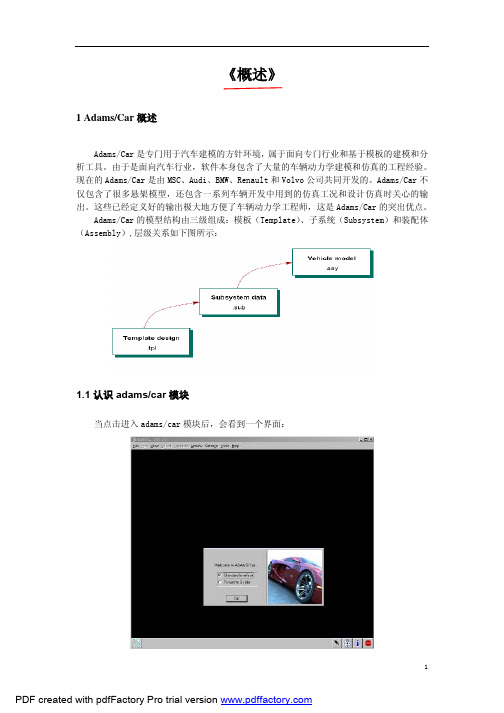
《概述》1 Adams/Car概述Adams/Car是专门用于汽车建模的方针环境,属于面向专门行业和基于模板的建模和分析工具。
由于是面向汽车行业,软件本身包含了大量的车辆动力学建模和仿真的工程经验。
现在的Adams/Car是由MSC、Audi、BMW、Renault和Volvo公司共同开发的。
Adams/Car不仅包含了很多悬架模型,还包含一系列车辆开发中用到的仿真工况和设计仿真时关心的输出。
这些已经定义好的输出极大地方便了车辆动力学工程师,这是Adams/Car的突出优点。
Adams/Car的模型结构由三级组成:模板(Template)、子系统(Subsystem)和装配体(Assembly),层级关系如下图所示:1.1认识adams/car模块当点击进入adams/car模块后,会看到一个界面:其中有Standard interface和Template Builder两个选项,默认的是选择Standard interface。
如果是初次安装和使用ADAMS2005,需要注意的是打开ADAMS/Car后并没有Template Builder选项,可以通过修改C:\Documents and Settings\管理者(用户名)文件下的acar.cfg文件来添加该选项。
用记事本打开该文件,如下图所示:系统默认的是standard用户类型,将其改为expert后重新打开ADAMS/Car后可以看到有Template Builder选项出现。
1.2 理解Standard interface(标准用户)和Template Builder(模板建立)的区别理解template builder和standard interface的区别是使用ADAMS/Car的关键一步。
1)Standard interface是建立和打开subsystem(子系统)、Assembly(装配体)的环境。
进入Standard interface后点击File>New可以看到在这个环境中可以建立子系统、悬架装配和整车装配。
基于Adams与Matlab的汽车电动助力转向系统的联合仿真
become
a
kind of technic in power steering system which is widely used nowadays.
The development of computer
technology and
the coming of virtual modeling
technology
system control simulation software were also introduced.
The
third chapter is devoted to modeling the process of this
article.That
is
described the simplification and assumptions
in detail.Modeling methods of various
subsystems
and vehicle
assembly were introduced too.
on
In chapter four,we focusing
the modeling process of electric power steering
in detail.Modeling methods of various
subsystems
and vehicle
assembly were introduced too.
on
In chapter four,we foccess of electric power steering
study and analysis
on
the
vehicle handing
6_ADAMS_CAR模块详细实例教程(转向篇)
6_ADAMS_CAR模块详细实例教程(转向篇) 6转向机建模...................................................................... . (186)6.1打开系统自带转向机模板 ..................................................................... .. (186)6.2修改转向机硬点 ..................................................................... (188)6.3修改助力特性 ..................................................................... . (189)6.4通讯器修改 ..................................................................... .. (189)6.5修改齿轮齿条传动比 ..................................................................... . (190)6.6保存模型...................................................................... .. (192)185《转向篇》6转向机建模轿车常用的转向机结构形式基本都是齿轮齿条式,为加快建模速度,在此推荐修改Adams/Car自带模板,主要是硬点、助力特性曲线、通讯器和齿轮齿条传动比的修改。
6.1打开系统自带转向机模板进入Template Builder点击File下拉菜单,选择Open:在出现的对话框Template Name一栏右击鼠标,Search><acar_shared>/template.tbl186在出现的文件夹里选择rack_pinion_steering.tbl。
基于adams汽车悬挂转向系统仿真与优化
基于adams汽车悬挂转向系统仿真与优化第一章引言Adams/Car模块简介:Adams/car模块是MSC公司与Audi,BMW等汽车公司合作开发的轿车设计模块,它能够快速建立高精度的车辆子系统模型和整车模型,它可通过高速动画直观的在线各个工况下车辆运动学和动力学相应,并与操纵稳定性,,制动性,平顺性有关的性能参数。
Adams/car的一个主要特点是基于模版。
建立模版即定义部件,部件之间的连接以及其他模版和试验台如何交换信息。
其中后者则是基于模版的产品所特有的。
Adams/car的共享数据库里提供了包括各种悬架,转向系,动力总成以及车身的模版,因此用户在建模时,无需从零开始,可调用已有的模版进行调整,从而大大简化建模过程。
如果在用户所要求的悬架模型或其他模型adams/car没有提供模版,这时就需用户在“template builder”中自行创建。
第二章正文2.1 悬架简介悬架是连接车轮与车架的弹性传力装置,它与汽车的操纵稳定性、平顺性及安全性等性能均有关。
悬架运动学主要研究内容是车轮定位参数与悬架变形量(或车轮跳动量) 的关系,随着各种形式的独立悬架的出现和应用,车轮定位参数在行驶过程中所引起的运动学变化对汽车操纵稳定性有着很大的影响。
双横臂悬架作为目前应用最广泛的独立悬架之一,其主要优点是:运动规律可以设计,对前轮定位参数的变化和侧倾中心位置的变化设定自由度较大,如果能适当地选择设计参数,可以使车辆得到很好的操纵性和平顺性。
本文针对某轿车行驶过程中所产生的过多转向问题,针对双横臂悬架的特性,利用ADAMS 软件对其进行建模分析,并根据仿真分析的结果确定优化目标对悬架运动学性能进行优化。
图2.2 基于双横臂前悬架子系统仿真2.2创建悬挂与转向系统轿车前后悬架为双横臂悬架。
主要结构由上下控制臂、转向节、转向横拉杆和减震器等组成。
其前悬架下控制臂为柔性体,如图 1 所示;而后悬架全部为刚体。
在建立悬架时,由于悬架左右是对称的,所以ADAMS/Car 中只需建立一侧的模型,另一侧会自动生成。
ADAMS_CAR模块详细实例教程
13柔性体介绍................................................ 错误!未定义书签。
柔性体引入ADAMS建模..................................... 错误!未定义书签。
打开原有的X5后悬架模板.............................. 错误!未定义书签。
将小连杆的模态中性文件导入ADAMS ..................... 错误!未定义书签。
利用Hyper Mesh及Motion View软件来生成模态中性文件MNF .. 错误!未定义书签。
创建小连接杆的CAD模型............................... 错误!未定义书签。
将iges格式文件导入到Hyper Mesh划分网格............. 错误!未定义书签。
创建材料............................................. 错误!未定义书签。
创建刚性单元......................................... 错误!未定义书签。
给刚性中心节点编号................................... 错误!未定义书签。
导出nastran模板格式文件............................. 错误!未定义书签。
创建h3d文件及MNF文件............................... 错误!未定义书签。
《柔性体篇》13柔性体介绍在模型中引入柔性体可以提高仿真的精度。
柔性体可采用模态中性文件(MNF)来描述。
该文件是一个二进制文件,包含了以下信息:几何信息(结点位置及其连接);结点质量和惯量;模态;模态质量和模态刚度。
可以利用ANSYS、NASTRAN、ABAQUS等限元软件包进行分析并将结果写成模态中性文件,输入到ADAMS/View或ADAMS/Car中,建立相应零件的柔性体。
adams car帮助文件实例教程car_tutorials
Tutorials and Examples For tutorials of overall product use, see:•Getting Started Using Adams/CarAdams/Car648Example Four-Post AnalysisExample Four-Post AnalysisAlthough this is an Adams/Car example, you can use the general concepts presented here to customizeany template-based product.•Setting Up and Running an Analysis: Teaches the expert user how to build and run a full-vehicle analysis with the four-post test rig.•Creating and Running a Macro: Introduces the concepts of creating and running a macro for the scenario given above.Tutorials and Examples649Example Event Files Example Event FilesIn Adams/Car, XML became the default file format for Driving Machine analyses. Although Adams/Car still supports driver control files (.dcf), it now automatically converts them to .xml. The .xml files are referred to as event files. Although the contents of the two files types look different, they contain the same event information. You work with .xml files through the Event Builder.In the shared Adams/Car database, we provide files in both .dcf and .xml format. These files are storedin the driver_controls.tbl directory/table.Adams/Car650Example .dcd FileExample .dcd FileThe following shows the architecture of a .dcd file and all the options you can set for a .dcd file. Itcontains options, logic, and general rules that you must follow when creating a .dcd file.[MDI_HEADER]FILE_NAME = filename.dcdFILE_TYPE = 'dcd'FILE_VERSION = 1.0 FILE_FORMAT = 'ASCII'(COMMENTS){comment_string}'Any comment'[UNITS]LENGTH = 'meter' || 'millimeter' || 'centimeter' || 'kilometer' || etc.FORCE = 'newton' || 'kilogram_force' || etc. ANGLE = 'deg' MASS = 'kg'TIME = 'sec'[CLOSED_LOOP]comment = stringsteering_control = 'none' || 'curvature' || 'path' || 'lat_acc'speed_control = 'none' || 'lon_vel' || 'lon_acc' || 'lat_acc' || 'path'ordinal = 'distance' || 'time'lon_vel_max = floatlon_vel_min = floatlon_acc_max = floatlon_acc_min = floatlat_acc_max = floatlat_acc_min = float(DATA)$ steering, speed$ 1 Case{none, none} -- null case, no data required!!$ 2 Case{none, lon_vel}$ 3 Case{none, lon_acc}$ 4 Case{none, lat_acc} -- NOT VALID$ 5 Case{none, path} -- NOT VALID{ ( distance || time ) && ( lon_vel || lon_acc ) }$ 6 Case{curvature, none} -- Must have distance with curvature { distance && curvature }$ 7 Case{curvature, lon_vel}$ 8 Case{curvature, lon_acc}$ 9 Case{curvature, lat_acc}$10 Case{curvature, path} -- NOT VALID{ ( distance || time ) && curvature && ( lon_vel || lon_acc|| lat_acc ) }$11 Case{path, none}$12 Case{path, lon_vel}$13 Case{path, lon_acc}$14 Case{path, lat_acc}{ x && y && ( lon_vel || lon_acc || lat_acc ) }$15 Case{path, path}{ x && y && time }$16 Case{lat_acc, none} -- NOT VALIDTutorials and Examples651Example .dcd File$17 Case{lat_acc, lon_vel}$18 Case{lat_acc, lon_acc}$19 Case{lat_acc, lat_acc} -- NOT VALID$20 Case{lat_acc, path} -- NOT VALID{ ( distance || time ) && lat_acc && ( lon_vel || lat_acc ) } [OPEN_LOOP]ordinal = 'time' || 'distance'{distance || time steering throttle brake gear clutch}*0.0 0.0 0.0 0.0 2 0.00.1 0.0 0.0 0.0 2 0.0*You can select distance or time and any combination of steering, throttle, brake, gear, and clutch.Example corresponding to $ 2 Case{none,lon_vel}:.....[CLOSED_LOOP]STEERING_CONTROL = 'NONE'SPEED_CONTROL = 'LON_VEL'ORDINAL = 'TIME'(DATA){ TIME, LON_VEL }0.0 27.7770.1 27.7770.2 27.7760.3 27.7750.4 27.7740.5 27.773.....Example corresponding to $ 7 Case{curvature,lon_vel}:.....[CLOSED_LOOP]STEERING_CONTROL = 'CURVATURE'SPEED_CONTROL = 'LON_VEL'ORDINAL = 'DISTANCE'(DATA){ DISTANCE, CURVATURE, LON_VEL }0.0 0.000 27.7771.0 0.002 27.7772.0 0.004 27.7773.0 0.006 27.7764.0 0.008 27.7755.0 0.010 27.7746.0 0.010 27.7737.0 0.010 27.7748.0 0.010 27.7749.0 0.010 27.77410.0 0.010 27.77411.0 0.010 27.77412.0 0.010 27.77413.0 0.010 27.774.....Adams/Car652Example Suspension Loadcase FileExample Suspension Loadcase FileIn Adams/Car, you can use loadcase files to specify different types of suspension analyses. The followingis an example loadcase file.$-----------------------------------------------MDI_HEADER[MDI_HEADER]FILE_TYPE = 'lcf'FILE_VERSION = 4.0FILE_FORMAT = 'ASCII'$-----------------------------------------------UNITS[UNITS]LENGTH = 'mm'ANGLE = 'degrees'FORCE = 'newton'MASS = 'kg'TIME = 'second'$$Generation Parameters: (Do Not Modify!)$ loadcase = 1$ nsteps = 10$ bump_disp = 100.00 rebound_disp = -100.00$ steering_input = angle$ stat_steer_pos = 0.00$$-----------------------------------------------mode[MODE]STEERING_MODE = 'angle'VERTICAL_MODE = 'length'$-----------------------------------------------data[DATA]$COLUMN: input type: type of input data: side:$ (c1) wheel z disp / force left$ (c2) wheel z disp / force right$ (c3) lateral force (y) left$ (c4) lateral force (y) right$ (c5 aligning torque (z-axis) left$ (c6) aligning torque (z-axis) right$ (c7) brake force (y) left$ (c8) brake force (y) right$ (c9) driving force (y) left$ (c10) driving force (y) right$ (c11) steering force / steer angle / rack travel{ whl_z_l whl_z_r lat_l lat_r align_l align_r brake_l brake_r drive_l drive_r steer}-100.0000 -100.0000 0.0000 0.0000 0.0000 0.0000 0.0000 0.0000 0.0000 0.0000 0.0000-80.0000 -80.0000 0.0000 0.0000 0.0000 0.0000 0.0000 0.0000 0.0000 0.0000 0.0000-60.0000 -60.0000 0.0000 0.0000 0.0000 0.0000 0.0000 0.0000 0.0000 0.0000 0.0000-40.0000 -40.0000 0.0000 0.0000 0.0000 0.0000 0.0000 0.0000 0.0000 0.0000 0.0000-20.0000 -20.0000 0.0000 0.0000 0.0000 0.0000 0.0000 0.0000 0.0000 0.0000 0.00000.0000 0.0000 0.0000 0.0000 0.0000 0.0000 0.0000 0.0000 0.0000 0.0000 0.00020.0000 20.0000 0.0000 0.0000 0.0000 0.0000 0.0000 0.0000 0.0000 0.0000 0.000040.0000 40.0000 0.0000 0.0000 0.0000 0.0000 0.0000 0.0000 0.0000 0.0000 0.000060.0000 60.0000 0.0000 0.0000 0.0000 0.0000 0.0000 0.0000 0.0000 0.0000 0.000080.0000 80.0000 0.0000 0.0000 0.0000 0.0000 0.0000 0.0000 0.0000 0.0000 0.0000100.0000 100.0000 0.0000 0.0000 0.0000 0.0000 0.0000 0.0000 0.0000 0.0000 0.0000653Tutorials and Examples Example Wheel-Envelope Input FileExample Wheel-Envelope Input FileThe following is an example of a wheel-envelope input file (.wen) that you can use to control a wheel-envelope analysis.$--------------------------------------------MDI_HEADER [MDI_HEADER]FILE_TYPE = 'wen'FILE_VERSION = 5.0 FILE_FORMAT = 'ascii'$--------------------------------------------UNITS [UNITS]LENGTH = 'mm'FORCE = 'newton'ANGLE = 'deg'MASS = 'kg'TIME = 'sec'$--------------------------------------------MODE [MODE]STEERING_MODE = 'angle'VERTICAL_MODE = 'length'$--------------------------------------------GRID [GRID] BOUNDARY_STEERING_GRID = 100.0 BOUNDARY_WHEEL_GRID = 20.0INTERIOR_STEERING_GRID = 100.0 INTERIOR_WHEEL_GRID = 20.0$--------------------------------------------DATA [DATA]$COLUMN: input type: type of input data: side:$ (c1) wheel z disp / force left $ (c2) wheel z disp / force right $ (c3) lateral force (y) left $ (c4 lateral force (y) right $ (c5) aligning torque (z-axis) left $ (c6) aligning torque (z-axis) right $ (c7) brake force (y) left $ (c8 brake force (y) right $ (c9) driving force (y) left $ (c10) driving force (y) right $ (c11) steering steer angle / rack travel $ {whl_z_l whl_z_r lat_l lat_r align_l align_r brake_l brake_r drive_l drive_r steer}-120.0 -120.0 0.0 0.0 0.0 0.0 0.0 0.0 0.0 0.0 -500.080.0 80.0 0.0 0.0 0.0 0.0 0.0 0.0 0.0 0.0 -500.090.0 90.0 0.0 0.0 0.0 0.0 0.0 0.0 0.0 0.0 -300.0120.0 120.0 0.0 0.0 0.0 0.0 0.0 0.0 0.0 0.0 -200.0120.0 120.0 0.0 0.0 0.0 0.0 0.0 0.0 0.0 0.0 200.0Note:For wheel-envelope input files, Adams/Car ignores columns three through ten: (left and right) lateral force, aligining torque, brake force, and driving force.Adams/Car654Example Wheel-Envelope Input File85.0 85.0 0.0 0.0 0.0 0.0 0.0 0.0 0.0 0.0 350.080.0 80.0 0.0 0.0 0.0 0.0 0.0 0.0 0.0 0.0 500.060.0 60.0 0.0 0.0 0.0 0.0 0.0 0.0 0.0 0.0 500.030.0 30.0 0.0 0.0 0.0 0.0 0.0 0.0 0.0 0.0 450.0-30.0 -30.0 0.0 0.0 0.0 0.0 0.0 0.0 0.0 0.0 450.0-75.0 -75.0 0.0 0.0 0.0 0.0 0.0 0.0 0.0 0.0 500.0-120.0 -120.0 0.0 0.0 0.0 0.0 0.0 0.0 0.0 0.0 500.0Tutorials and Examples655Example Wheel-Envelope Output File Example Wheel-Envelope Output FileA wheel-envelope output file (.wev) contains a header and a data table, as explained next.The first three lines comprise the header and contain the following information, in this order:•Type of file•Adams dataset title•Date and time of file creationThe table that follows the header contains the following information:•The first column shows the solution step number•Columns 2-4 show the data for the left wheel center x, y, z•Columns 5-7 show the data for the left wheel axis point x, y, z•Columns 8-10 show the data for the right wheel center x, y, z•Columns 11-13 show the data for the right wheel axis point x, y, zThe following is an example of a wheel-envelope output file:Adams/Car Wheel Envelope Analysis Output File - acar_v10.0Adams/Car Assembly2000-01-19 16:41:211-4.2702-673.57205.00-348.83-1611.7170.297.0293670.69205.00303.631620.7107.882-4.6463-681.45225.00-344.63-1621.7206.15 6.7629678.55225.00307.971628.3139.913-4.9532-687.82245.00-340.16-1630.0239.60 6.5706684.92245.00311.281634.4170.264-5.2433-692.82265.00-334.67-1637.0271.40 6.3755689.93265.00314.351639.0198.895-5.5240-696.55285.00-328.07-1643.0301.70 6.1779693.66285.00317.431642.1225.766-5.7905-699.08305.00-320.38-1648.0330.44 5.9864696.18305.00320.671643.8250.767-6.0372-700.45325.00-311.59-1652.1357.51 5.8099 697.55325.00324.251644.1273.768-6.2583-700.71345.00-301.72-1655.3382.78 5.6583697.79345.00328.311643.0294.559-6.4469-699.89 365.00-290.74-1657.8406.03 5.5424696.93365.00333.041640.3312.8810-6.5953-698.01385.00-278.64-1659.4426.98 5.4752695.00385.00338.631636.2328.39 ..........Adams/Car656Example Plot Configuration FileExample Plot Configuration FileThe following is an example of an Adams/Car plot configuration file:$----------------------------------------------------------------------PAGE[PAGE]PAGE_LAYOUT = 11.0NUMBER_OF_PLOTS = 1.0PAGE_NAME = page_1HEADER_LEFT_LINES = 1.0HEADER_LEFT_LINE_0_TEXT = 'Header Left'HEADER_LEFT_TEXT_FONT_SIZE = 9.0HEADER_LEFT_LINES = 1.0HEADER_LEFT_COLOR = 788529153.0FOOTER_RIGHT_LINES = 1.0FOOTER_RIGHT_LINE_0_TEXT = 'Footer Right'HEADER_LEFT_LINES = 1.0HEADER_LEFT_LINE_0_TEXT = 'Header Left'FOOTER_RIGHT_TEXT_FONT_SIZE = 9.0FOOTER_RIGHT_COLOR = 788529153.0$----------------------------------------------------------------------PLOT[PLOT]INDEX = 0.0NAME = 'plot_1'TIME_LOWER_LIMIT = 0.0TIME_UPPER_LIMIT = 0.0AUTO_DATE_STAMP = 1.0AUTO_ANALYSIS_NAME = 1.0AUTO_SUBTITLE = 0.0AUTO_TABLE_HEADER = 1.0(LEGEND){placement xloc yloc zloc fill }2 55.46 85.03 0.00 1(PLOT_BORDER){color line_style line_weight}788529153 1 1.0(PRIMARY_GRID){color line_style line_weight}788529165 1 0.5(SECONDARY_GRID){color line_style line_weight}788529165 1 0.5(LEGEND_BORDER){color line_style line_weight}788529153 1 1.0(NOTES)NUMBER_OF_NOTES = 3.0(NOTE_1){name font color autopos rotation alignment xloc yloc zloc isDate isAnalysisnumStrings}'analysis' 9 788529153 0 0.0 2 54.3200 4.7836 0.0000 0 1 0 1STRING_1_TEXT = 'Analysis: test1_parallel_travel'(NOTE_2){name font color autopos rotation alignment xloc yloc zloc isDate isAnalysisnumStrings}'date' 9 788529153 0 0.0 2 117.8513 4.7836 0.0000 1 0 0 1STRING_1_TEXT = '15:52:54 11-MAY-98'(NOTE_3)Example Plot Configuration File{name font color autopos rotation alignment xloc yloc zloc isDate isAnalysis numStrings}'NOTE_3' 10 788529163 1 0.0 4 82.6197 56.0575 0.0000 0 0 0 1STRING_1_TEXT = 'This is my note'(PLOT_AXES){axis_name type label scaling divisions low_limit up_limit color fontrotation alignment placement axis_offset axis_color label_autoposlabel_offset label_xloc label_yloc tic_color minor_divs auto_divs use_divs incs trailing_zeros dec_places sci_lower sci_upper num_font num_color}'vaxis' 'vertical' 'No Units' 'linear' 8 0 0 788529153 9 90.0 3 0 0.0 788529153 0 10.9 43.4 49.3 788529153 2 1 1 1.0 0 4 -4 5 9.0 788529153'haxis' 'horizontal' 'Time (sec)' 'linear' 3 0 0 788529153 9 0.0 2 3 0.0 788529153 0 6.5 86.1 4.8 788529153 2 1 1 5.0 0 4 -4 5 9.0 788529153$----------------------------------------------------------------PLOT_CURVE [PLOT_CURVE]NAME = 'curve_1'PLOT = 'plot_1'VERTICAL_AXIS = 'vaxis'HORIZONTAL_AXIS = 'haxis'HORIZONTAL_EXPRESSION = 'toe_angle.TIME'VERTICAL_EXPRESSION = 'toe_angle.right'Y_UNITS = 'no_units'X_UNITS = 'time'LEGEND_TEXT = 'Right'COLOR = 'red'STYLE = 'solid'SYMBOL = 'none'LINE_WEIGHT = 2.0HOTPOINT = 0.0INCREMENT_SYMBOL = 1.0Adams/Car Dynamic Suspension AnalysisThis example demonstrates the ability to carry out Dynamic Suspension Analysis . Earlier, the Suspension Assembly was limited to carry out only quasi-static simulation. Now, your suspension assembly is simulated with Adams/Solver Simulate/Dynamic command.This feature allows you to directly provide a RPCIII file or define View Functions to specify Jack and Steering motion as a function of displacement, force etc.Model DescriptionInvestigate the model and carry out a Dynamic AnalysisHere you first analyze a double wishbone suspension with rigid lower control arm1.Start Adams/Car , Select Standard Interface .2.Create a new Suspension assembly: File - New - Suspension Assembly . Fill the dialog box as indicated below. To select the subsystems, Right-click - Search - <acar_shared> to open the file browser.A Suspension Assembly consisting of adouble wishbone suspension and a rack and pinion steering system is provided.A dynamic suspension analysis is carriedout to actuate the wheel pads across arange of frequencies. We are interested inlooking at the lower control arm bushingforce and how the force changes byreplacing the rigid lower control arm bya flexible body. In addition, we use theflex body swap dialog box to switch arigid lower control arm with a flexibleone. We then plot the stress on theflexible body node and visualize it.Adams/Car Dynamic Suspension Analysis3.The suspension assembly should be displayed.4.To simulate using the Dynamic Solver Statements, go to Simulate - Suspension Analysis -Dynamic.5.You will use View Functions to define the vertical displacement of the Jack. The followingfunction steps up the bounce-rebound amplitude from 10 mm to 30 mm with a frequency of 2 Hz: step(time,2,10*sin(4*pi*time),8,30*sin(4*pi*time))(Tire Forces can be added using the function like Static Loads Analysis)6.To animate the results, from the Review menu, select Animation Controls. Animate the modeland observe the change in the suspension travel.Review the resultsPlot the bushing force in the lca_front bushing:1.Hit the F8 key in Adams/Car to switch to Adams/PostProcessor.2.Locate the bkl_lca_front_force and bkr_lca_front_force REQUEST under user-definedREQUESTs:Adams/Car Dynamic Suspension AnalysisThe fz_front component corresponds to magnitude of the force in the Z direction. Plot this quantity to obtain a figure similar to the following:Change Rigid Lower Control arm to be a Flexible BodyHere you use the Flex body Swap dialog box feature available in the Standard interface to replace the left rigid lower control arm with a flexible body. The MNF file used for representing this flex body is created in Nastran.To replace the lower control arm:1.Go to Adjust - General Part - Rigid to Flex. This displays the flex body swap dialog box.2.Right click the Current Part Field - Pick and select the Left Lower control arm. In the MNF Filefield, Right-click- Search - <acar_shared>\flexbodys.tbl and select the LCA_left_tet.mnf file.3.Click on the Connections tab next and highlight the Move column and click PreserveExpression button and click OK.Adams/Car Dynamic Suspension Analysis4.Now, the rigid lower control arm in red is replaced by the white flexible body.Simulate the ModelYou again carry out a dynamic analysis with this model now containing a flexible body.1.Go to Simulate - Suspension Analysis - Dynamic. the Output Prefix to be Rigid_Flex and keep the remaining dialog box unchanged. After the simulation is successful, animate the model to make sure it is behaving as expected. Review & Compare ResultsHere you plot the bushing force for the lower control arm and compare the force on left and right side. To review the results:1.Locate the bkl_lca_front_force and bkr_lca_front_force REQUEST under user-definedREQUESTs:2.Because of the left lower control arm being a flexible body, note the difference in the bushingforce.Optional: Load Durability Plugin to display Stresses and Identify the HotspotsHere you will load the Durability Plugin and identify the hot-spots on the flexible lower control arm and also plot the nodal stresses. For better visualization, in the Adams/Car Standard Interface change the background color from Black to Gray (Settings - View Background Color).To Display Stresses and animate the flex body:1.Change to Adams/Postprocessor and switch to Animation mode.2.Go to View - Load Animation - select Rigid_Flex_dynamic to load the animation.3.Go to Tools - Plugin Manager and check the load Adams/Durability option.Adams/Car Dynamic Suspension Analysis 4.In the Animation tab right click the Component field and select the flexible bodygel_lower_control_arm_flex. This only displays the flexible body and not the whole model.5.Select the Contour Plots tab; set Contour Plot Type to Von Mises Stress and check DisplayLegend.6.Select the Hot Spots tab; check Display HotSpots and fill the dialog box as shown below. Youare interested in looking at the top 2 hotspots on the flexible body.7.Play the animation; you would observe the change in stress with the hot spots being identified.8.From the above exercise, you can note that Node with ID 709 experiences the maximum VonMises Stress. You can now, plot the stress at this node. Go to Durability menu at the top and select Nodal Plots. The dialog for Nodal Plots pops up. In the Select Node List field, fill in 709, Check Von Mises and click OK.9.Switch back to Plotting mode in the Adams/PostProcessor, Set the Source to be Result Sets;select gel_lower_control_arm_flex_Stress and component to be node_709_Von_Mises. Your plot should look something like shown below.Tutorials and Examples667Adams/Car Dynamic Suspension AnalysisRemarks•The above example, demonstrates a simple use of applying a non standard excitation to a suspension assembly. You could use an RPCIII file from test data to actuate your suspension oruse other Adams/View functions. An example RPCIII file (roadprofile_lr_channels.drv) hasbeen provided in the shared car database with your Adams installation(install_dir\acar\shared_car_database.cdb\loadcases.tbl).•While animating or during plotting of the hot spots/stresses for the first time, you may see a progress bar. This is showing the caching of the Flex Cache Files for improving performance forfuture animation and post processing.Adams/Car Adding the vertical setup mode of Adams/Car Suspension Testrig 668Adding the vertical setup mode of Adams/Car Suspension TestrigThis example demonstrates the enhancement of MDI_SUSPENSION_TESTRIG for quasi-staticsuspension analysis. The vertical mode named "VERTICAL_MODE_FOR_SETUP" in loadcase file is added to the suspension testrig. "VERTICAL_MODE_FOR_SETUP" means the vertical control method at time=0. Early the user could select only the "VERTICAL_MODE" for the simulation. This feature allows you to set the vertical mode method at the both condition the setup phase(time=0) and the simulation phase.This new mode is very important for the model including adjustable force. Because when the usercorrelates with test data, it is important for users how the initial condition is setup in real world and in the simulation.Model DescriptionPerforming the analysis in order to investigate the vertical setup mode.Here you first analyze a double wishbone suspension including adjustable force.1.Start Adams 2013, Select Standard Interface .2.Create a new Suspension assembly: File - New - Suspension Assembly . Fill the dialog box as indicated below. To select the subsystems, Right-click - Search - <acar_shared> to open the file browser.A Suspension Assembly consisting of a double wishbone suspension includingadjustable force and a rack and pinionsteering system is provided.We carry out quasi-static suspensionanalysis with two setup mode forvertical control. One is"wheel_center_height". Other is"contact_patch_height. And we thenplot the toe angle in order to make surethe differences.Tutorials and Examples669Adding the vertical setup mode of Adams/Car Suspension Testrig3.The suspension assembly should be displayed.4.Go to Adjust - Adjustable Force. And select".frontsusp_acforce.TR_Front_Suspension_torsional.afl_toe_adjustment" for the "Adjustable Force" field. Then you can see the desired value (-0.5). This value means that the toe angle is adjusted to -0.5 at setup phase.5.Go to Simulate - Suspension Analysis - Parallel Wheel Travel…6.Set up the analysis as follows. In this case, the vertical travel of the wheel is controlled to keep0mm in setup phase.Adams/Car670Adding the vertical setup mode of Adams/Car Suspension Testrig7.Select OK.8.Go to Simulate - Suspension Analysis - Parallel Wheel Travel… again9.Set up the analysis as follows for the second analysis. In this case, the vertical travel of thecontact patch is controlled to keep 0mm in setup phase.671Tutorials and Examples Adding the vertical setup mode of Adams/Car Suspension Testrig10.Select OK.Review the resultsPlot the toe angle in two analyses:1.Hit the F8 key in Adams/Car to switch to Adams/PostProcessor.2.From the simulation list, select the two analyses.3.From the right of the dashboard, set Independent Axis to Data . (The Independent Axis Browser appears. You perform the next four steps in the browser.)4.From the Request list, select wheel travel . You might have to scroll down to see this entry.5.From the Component list, select vertical_left .6.Select OK.Note:"Absolute" at "Control Mode" means that the vertical displacement is controlled thedisplacement with absolute value. "Relative" means that the displacement is relative to the position at the setup phase.Adams/Car672Adding the vertical setup mode of Adams/Car Suspension Testrig7.Locate the testrig.toe_angle REQUEST under user-defined REQUESTs. And select left incomponent list.8.Select Add curve. You can see the plot of wheel_travel vs toe_angle.The toe angle in Red line(case1...) should be -0.5 by adjustable force when wheel_travel is 0.9.Create New page.10.From the right of the dashboard, set Independent Axis to Data. And select jfl_jack_force_datain request list and displacement in component list.11.Plot the toe angle again. You can see the plot of contact_patch_height vs toe_angle.The toe angle in Blue line(case2...) should be -0.5 by adjustable force when contact_patch_heightis 0.Tutorials and Examples673Adding the vertical setup mode of Adams/Car Suspension TestrigRemarks•"VERTICAL_SETUP_MODE" is available with all quasi-static suspension analysis. When you create the loadcase file, the setup mode is described as follows in loadcase file.[MODE]STEERING_MODE = 'angle'$ wheel_center_height/ contact_patch_heightVERTICAL_MODE_FOR_SETUP = 'contact_patch_height'VERTICAL_MODE = 'wheel_center_height'VERTICAL_TYPE = 'absolute'COORDINATE_SYSTEM = 'vehicle'•"Control Mode" is also described as follows in loadcase file.[MODE]STEERING_MODE = 'angle'$ wheel_center_height/ contact_patch_heightVERTICAL_MODE_FOR_SETUP = 'contact_patch_height'VERTICAL_MODE = 'wheel_center_height'VERTICAL_TYPE = 'absolute'COORDINATE_SYSTEM = 'vehicle'Adams/Car Adding the length mode for roll analysis of Adams/Car Suspension Testrig 674Adding the length mode for roll analysis of Adams/Car Suspension TestrigThis example demonstrates the enhancement of MDI_SUSPENSION_TESTRIG for quasi-staticsuspension analysis. The length mode is added to roll analysis of the suspension testrig. The length mode means that the user can define the vertical length of the center of the table for roll analysis. Early the user could set only vertical total force. This feature allows you to set the vertical mode the either of Force or Length for roll analysis.Model DescriptionPerforming the roll analysis in order to investigate the vertical mode.Here you first analyze a double wishbone suspension including adjustable force.1.Start Adams 2013, Select Standard Interface .2.Create a new Suspension assembly: File - New - Suspension Assembly . Fill the dialog box as indicated below. To select the subsystems, Right-click - Search - <acar_shared> to open the file browser.A Suspension Assembly consisting of adouble wishbone suspension including adjustable force and a rack and pinionsteering system is provided.We carry out roll analysis in quasi-static suspension analysis with twosetup mode for vertical control. One is"Force". Other is "Length". And wethen plot some requests in order tomake sure the differences.Tutorials and Examples675 Adding the length mode for roll analysis of Adams/Car Suspension Testrig3.The suspension assembly should be displayed.4.Go to Adjust - Adjustable Force. And select".frontsusp_acforce.TR_Front_Suspension_torsional.afl_toe_adjustment" for the "Adjustable Force" field. Then you can see the desired value (-0.5). This value means that the toe angle is adjusted to -0.5 at setup phase.5.Go to Simulate - Suspension Analysis - Roll & Vertical Force…6.Set up the analysis as follows. In this case, the vertical mode is controlled with Force modeduring the simulation.。
ADAMS_CAR模块实例(转向篇)
6转向机建模 (186)6.1打开系统自带转向机模板 (186)6.2修改转向机硬点 (188)6.3修改助力特性 (189)6.4通讯器修改 (189)6.5修改齿轮齿条传动比 (190)6.6保存模型 (192)185《转向篇》6转向机建模轿车常用的转向机结构形式基本都是齿轮齿条式,为加快建模速度,在此推荐修改Adams/Car自带模板,主要是硬点、助力特性曲线、通讯器和齿轮齿条传动比的修改。
6.1打开系统自带转向机模板Template Builder进入在出现的对话框Template Name一栏右击鼠标,Search><acar_shared>/template.tbl186在出现的文件夹里选择rack_pinion_steering.tbl。
点击“打开”。
点击OK,将自带转向机模板文件调入建模界面,如下图所示:187BMW X5转向机各硬点如下表所示:点击Build>Hardpoint>Table,打开自带模板的硬点表:188把上表内的各硬点值修改为X5的实际硬点值。
6.3修改助力特性点击Build下拉菜单,选择Steering Assist。
出现如下对话框:如果设置转向助力的话勾选Steering Assist Active,其特性文件是系统自带的,可根据实际情况做出修改。
6.4通讯器修改一般情况默认自带模板的通讯器命名,需要注意的是其中的Swich part选项。
189190在出现的对话框里右击鼠标,Switch Part>Guesses>sws_rack_house_mount 。
如下图所示:由于X5的转向机是固定在前副车架上,则要将Switch To Part 一栏选为 ._rack_pinion_steering.mts_rack_housing_to_suspension_subframe ,如下图所示:点击OK 。
6.5修改齿轮齿条传动比从下拉菜单选择Build>Gear>Reduction Gear>Modify 。
ADAMS_Car在汽车动力学仿真中的应用(简单过程介绍)
2
+ a yS FWs
右前轮法向力
FZR , i =
χ+ < - ax
W
χ[ L ( 1 - <) - x ] ay ρ 0
×
2
- a yS FWs ( 5)
左后轮法向力
FZR , o =
χ< - ax
W
χ[ L ( 1 - <) - x ] ay ρ 0
×
2
- a yS FWs ( 6)
右后轮法向力 式中 , < 为后轴静载荷除以总重 ;χ 为中心高度除以轴 距 ;ρ 0 为转弯曲率半径 ; ax 为纵向减速度 ; a y 为横向加 速度 ; L 为轴距 ; S F 为前悬架刚度 ; S R 为后悬架刚度 ;
工业出版社 ,2001.
[3] 雷雨成 1 汽车系统动力学仿真[M]1 北京 ,国防工业出版社 ,19971
第 23 卷增刊 王 利 等 : ADAMS/ Car 在汽车动力学仿真中的应用
157
Dynamics Simulation of Vehicle Using ADAMS/ Car
Car 模块与 Driver 模块相结合可以进行汽车整车的闭
环反馈控制仿真 。因此 ADAMS/ Car 在汽车动力学分 析和仿真上具有很好的应用前景 。 参 考 文 献
[ 1 ] 余志生 1 汽车理论 [M] 1 北京 : 机械工业出版社 ,2000171~1021 [ 2 ] 郑建荣 1ADAMS — — — 虚拟样机技术入门与提高 [M] 1 北京 : 机械
又由公式 Φ=
FXR FX F + FXR ( 1)
156
四川工业学院学报 2004 年 由图 7 所示数据得 ,制动时车辆半径变小 , 车身有侧 向位移量 ,经计算得 2105m 。 汽车在转弯制动时 , 由纵向制
adams_car
快捷键:F9:adams/car的standard和template界面进行切换;Admas/car进入adams view:Tools---command navigator---acar---interface---switch----aview;数据浏览:tools---database navigater;Ctrl+z:返回;Bug:创建part时选择center between two points时下面有三个坐标点,---先选between 3 …,再选between 2…即正常显示;一、build建模1.1 hardpointsLeft:在左侧创建点,同时在右侧自动创建对称的点;(正前方为x负方向)形状:六半雪花状,绿色;1.2 constructionframe结构框包含位置和方向信息,用于创建part时的定位;(1)如果定位在一个点,orient axis to point使用同一个点,则相当于定向时三个欧拉角为0,与大地坐标系一致;1.3 part1.3.1 general part1)一般部件指位置、方向、质量、惯量确定的刚体;2)创建方式①new创建的刚体不具有几何形态,但包括质量、位置、方向;创建不具有几何的体:直接创建即可;具有几何的体:先用new创建,然后再创建geometry,附属于该体即可;(这种情况new创建时可以随便设置质量和转动惯量,然后创建几何时勾选caculate …即可)②wizard创建的刚体有几何形态,连杆(需要两个硬点)、三角臂(三个硬点);效果等于:先创建new体,然后创建geometry,只是通过geometry创建的part种类多一些;3)属性(1)location dependency:定位体的位置:(2)orientation dependency:定位体的方向:Euler angles:313规则,即绕z轴转---绕x轴转---绕轴转;Orient to zpoint-xpoint:所选两个点的连线垂直于zx平面;1.3.2 安装件(mountpart)1)基本属性以一个硬点定义安装件的位置;无质量部件;用于确定本系统中什么部件与其他系统中哪个部件相连;安装部件可以和其他部件创建约束;2)命名如果选择了inherit,则会自动创建一个通讯器(用于和其他系统部件匹配);例:subframe_to_body - cil[r]_subframe_to_body(通讯器名称);3)修改在adams/car中对左右对称的mount进行修改,比如修改左件,则右件及通讯器都会进行相应修改;切换到adams/view中则不会;如果在adams/view中修改之后再在car1.3.3 转接件(switch)1)基本属性无质量部件;用于多个部件的拓扑连接,需要一个硬点和多个part;随着组装的完成,转接件会被自动删除;1.4 geometry1.4.1 armThickness(10):以三个点所确定的平面为中间平面,两边各5mm;1.4.2 颜色Maize:玉米黄;1.4.3 outline创建outline时,如果一个环无法生成自己所需的路线,可以沿着某条路径进行连接,需要返回时,沿原路线返回,估计画重复的线,软件能自动删除;1.5 force1.5.1 damper减震器:两个体,两个体上的两个点;1.5.2 spring弹簧:两个体,两个体上的两个点;DM可以计算当前两个点之间的长度,作为弹簧的安装长度;1.6 suspension parameters1.6.1 toe/camber创建前束和外倾角度:前束角度为正,外倾角度为负;一般创建了toe/camber之后,会创建一个frame框进行定位,方便之后创建轮毂等体;1.6.2 characterarray设置车轮转向中心线,即转向节主销轴线;Geometry通过两点创建线;(创建之后线是不可见的)1.7 attachment1.7.1 joint1)active激活状态Always:总是激活;Kinematic mode:激活状态为运动学;(1)使用kinematic时:常常创建两个连接副(都设置为激活状态),执行运动学分析时使用铰接副,进行顺应态分析时,用具有弹塑性的轴套取代铰接副;1.8 基本操作1.8.1 平移整体平移:转换到adams/view框选所有,进行平移操作;在adams/car中build---hardpoints---table,对所有硬点进行平移操作即可;因为adams/car是从下到上进行建模的;1.8.2模板进行切换12版没有模型树,模型切换:view---template;1.8.3 删除可以直接右键删除;多项删除:edit---delete;1.9 communicator1.9.1 communicator test输入两个模板,输入其属性(位置front\rear\body…);进行通讯器匹配检查,检查两个模板匹配的通讯器,以便进行通讯器修改;二、理论知识2.1 转向结构2.1.1adams/car结构件1)名称Steering gear:转向器;Steering wheel:转向盘、方向盘;!以下4个为模型中方向盘下的4个命名Steering column:转向柱管;Intermediate shaft:中间轴;Steering shaft:传动轴;Tierod:横拉杆;P.1itman arm:转向摇臂();Rack housing:齿条罩;Rack:齿条;Steering shaft:传动轴;Pinion:驱动齿轮;Subframe :副车架;Rack pinion Steering:齿轮齿条转向系;Idler arm:转向从动臂Pitmanarm:转向摇臂;Pivot:支点,center:中心点;Steering gear:转向机;2.1.2 结构图2.1.3转向系1)齿轮齿条转向系2)平行杆转向系2.1.4 问题1)._rack_pinion_steering转向盘和mts_steering_column_to_body(安装件)之间为旋转副,安装件为什么会是红色套筒;2.2 前悬架2.2.1前悬架结构件1)名称Control arm:控制臂;Upright:立柱;Strut:支柱;Spindle:主轴;Leaf spring:钢板弹簧;Wheel carrier:转向节三角臂;Carrier link:转向节立柱;Hub:轮毂;Knuckle:关节点;Tripot:玻璃珠;Differential:差动装置的;tripot_to_differential;Kingpin:转向立柱;Toe/camber :前束外倾;Hub_bearing:轮毂方位;Subframe:副架;2.2.4 问题MDI_Demo_Vehicle_lt.TR_Front_Suspension1)joint为什么会有.MDI_Demo_Vehicle_lt.TR_Front_Suspension.ger_lower_cont rol_arm2;低控制臂和低控制臂2之间为移动副,低控制臂2和立柱之间为球绞;高控制臂与立柱之间为球绞?;外横拉杆和内横拉杆之间为移动副;.MDI_Demo_Vehicle_lt.TR_Front_Suspension.bur_jounce_stop是什么?2.2.5 实例1)macpherson前悬挂(1)拓扑结构部件内外连接:控制臂:滑柱:转向节:2.3 车身body2.3.1 结构1)名称Chassis:底盘;2.4 稳定杆2.4.1 结构1)名称Antiroll bar:稳定杆;arb_...三、仿真3.1问题处理(1)Id为53号的joint有错误;查找该joint:设置icons---不显示parts---在约束上右键info即显示其编号(只有装配之后才有编号);。
基于ADAMS软件的转向梯形计算机辅助设计
α文章编号:100127445(2003)0320246203基于ADAM S 软件的转向梯形计算机辅助设计韦超毅1,蒋国平2,周从钜1,谢美芝1(1.广西大学林学院,广西南宁530001;2.江苏大学汽车与交通工程学院,江苏镇江212013)摘要:转向梯形机构是使汽车转向时实现内、外轮理想转角关系的核心部件.本文应用机械系统动力学分析软件ADAM S 建立前悬架-转向系统的统一仿真模型,同时对前悬架和转向系统的运动学特性进行仿真分析,综合考虑其实际梯形转向特性与理论转向特性的接近性、转向梯形与悬架运动的协调性问题,为转向梯形设计提供了高效、精确的实用方法.关键词:ADAM S 软件;悬架;转向梯形中图分类号:U 463.2 文献标识码:A数字化虚拟样机技术是缩短汽车研发周期,降低开发成本,提高产品设计和制造质量的重要途径.目前国外许多汽车企业都已经大规模应用多媒体分析程序来进行汽车的运动学和动力学仿真,并且利用系统仿真的概念,从设计-试验-改进设计-再试验-再设计的设计理念转为设计-仿真-试验,使设计中的主要问题利用数字化虚拟样机技术在设计初期得以解决.本文利用机械系统动力学分析软件ADAM S 建立某国产轿车的前悬架-转向系统动力学模型,将前悬架和转向系统作为一个整体来进行系统研究,探讨了ADAM S 软件在断开式转向梯形设计中的应用.1 汽车理论转向特性与转向梯形设计为了确保汽车在转弯时四轮作纯滚动而不产生滑移,必须使两转向前轮轴的延长线与后轮轴延长线的交点作为转向中心进行转向,即所谓的阿克曼(A ckerm an )理论转向特性[1、2].此时,转向内外轮转角应满足如下关系:ctg Ηo -ctg Ηi =K L ,式中Ηo 为转向外轮转角,rad ;Ηi 为转向内轮转角,rad ;K 为两主销中心线延长线到地面交点的距离,m ;L 为轴距,m .这就是在设计转向梯形时,正确处理内、外轮转角关系的理论依据.转向梯形机构的主要功能是实现汽车转向时内、外轮理想的转角关系,但现有的汽车转向梯形的设计是不可能在整个转向范围内与阿克曼理论完全吻合的,只是尽可能与理论转向特性相接近.目前转向梯形设计、计算和校核的主要方法是平面转向梯形设计法和空间转向梯形设计法.平面转向梯形设计法,即平面作图法和平面解析法,也就是把实际空间运动的转向梯形机构投影到平面上进行分析计算,误差是明显的,特别是独立悬架上采用断开式转向梯形,由于杆件数量多,机构复杂,更会产生较大的计算误差.空间转向梯形设计法是运用空间机构学理论对实际断开式转向梯形机构进行空间分析和计算,在此基础上对转向梯形机构进行综合设计使其实现较理想的内、外轮转角关系.2 前悬架-转向系统的仿真模型ADAM S CA R 模块是机械系统动力学分析软件ADAM S 软件包中的一个专业化模块,主要用于对轿车(包括整车及各个总成)的动态仿真与分析.应用ADAM S CA R 对悬架系统进行建模原理相对比较简单,模型原理与实际的系统相一致.考虑到汽车基本上为一纵向对称系统,软件模块已预先对建第28卷第3期2003年9月广西大学学报(自然科学版)Jou rnal of Guangx i U n iversity (N at Sci Ed )V o l .28,N o.3 Sep t .,2003 α收稿日期:20021103;修订日期:20030725基金项目:江苏大学企业博士后科研基金作者简介:韦超毅(1965),男,广西浦北人,广西大学林学院讲师,江苏大学在读博士生.742第3期韦超毅等:基于ADAM S软件的转向梯形计算机辅助设计5 结 论综上所述,本文得到如下研究结论:(1)目前转向梯形设计所采用的平面梯形设计法和空间梯形设计法,局限于解决实际梯形转向特性与理论转向特性的接近性问题,不能有效地解决转向梯形与悬架运动的协调性问题.(2)本文以系统研究的观点,建立能真实有效地反映该轿车前悬架和转向系统的实际运动学特性的统一仿真模型,避免传统转向梯形模型设计方法的不足.(3)基于所建立的前悬架-转向系统仿真模型,利用ADAM S 软件对前悬架-转向系统的运动学特性进行仿真分析,综合考虑其实际梯形转向特性与理论转向特性的接近性、转向梯形与悬架运动的协调性问题,从而确定转向梯形的断开点的位置,为转向梯形设计提供了高效、精确的实用方法.参考文献:[1] 龚微寒.汽车现代设计制造[M ].北京:人民交通出版社,1995.[2] 王望予.汽车设计[M ].吉林:机械工业出版社,2000.[3] 耶尔森.赖姆帕尔.汽车地盘基础[M ].北京:科学普及出版社,1992.[4] 阿达姆.措莫托.汽车行使性能[M ].北京:科学普及出版社,1992.Com puter -a ided design of steer i ng trapezo id ba sed on ADAM S sof twareW E I Chao 2yi 1,J I AN G Guo 2p ing 2,ZHOU Cong 2ju 1,X IE M ei 2zh i1(1.Co llege of Fo restry ,Guangx i U n iversity ,N ann ing 530001,Ch ina ;2.Co llege of A u tomob ile and T raffic Engineering ,J iangsu U n iversity ,Zhen jiang 212013,Ch ina )Abstract :T he A ckerm an steering trap ezo id is the key p art on veh icle ,w h ich can en su re the A ckerm an steer angle w hen steering .T he ADAM S softw are is u sed to bu ild the fron t su sp en si on and steering system si m u lati on m odel and si m u lati on analysis of steering trap ezo id .A n accu rate and u sefu l m ethod is p rovided fo r design ing the sp litting A ckerm an steering trap ezo id .Key words :ADAM S softw are ;su sp en si on ;steering trap ezo id(责任编辑 刘海涛)842广西大学学报(自然科学版)第28卷 。
