TP10
uiuc信——精选推荐
uiuc信uiuc信篇一:有心者获UIUC金融工程录取有心者获UIUC金融工程录取学生姓名:栋同学毕业院校:南京某211大学数学专业相关成绩:GPA:3.3, IBT:102;GRE:320 申请结果:UIUC金融工程;USC金融数学;罗格斯大学金融工程;波士顿大学金融工程;优势:1. 学生是数学专业,对于申请金融工程非常有利。
2. 栋同学辅修了金融课程,对于申请金融工程也十分有利。
3. 栋同学的GRE成绩还不错,按照之前学生案例有录取UIUC的可能。
劣势:1. 栋同学的实习经历不是很理想,因为同时辅修了金融课程,所以时间上不够,操作起来十分困难。
【明智慧德专家方案】栋同学是一个十分努力的女孩子,对于去美国读金融工程十分向往,因此很早就加入了我们慧德留学。
我们对于栋同学也十分的看好,她的数学专业背景和辅修金融课程对于申请美国的金融工程非常有利。
同时,由于栋同学准备的非常早,因此有充足的时间去提高语言成绩。
在我们的督促和帮助下,她的GRE成绩最后达到了320,IBT成绩到了102,已经达到了美国名校金融工程的申请标准。
为此我们也感到十分的欣慰。
我们给她选校的时候是按照专业排名+地理位置的思路。
在同一个学校存在两种类似专业的情况下,申请跟她背景最匹配的一个。
比如在申请USC的时候,有两种项目可以选:金融数学和金融工程,由于学生专业是数学,缺乏工科背景,所以我推荐了金融数学。
结果证明我们的选择是正确的,确实也申请上了USC金融数学。
申请金融工程最重要的一点就是文书和套磁(虽然大家都认为套磁在申请金融工程硕士中的意义不大)。
文书中,我们巧妙的把她的学术背景/小科研背景/对专业的理解/清晰的职业目标/对所申请学校的热情结合了起来。
这样让学校能一目了然地看到学生为申请该校所做的preparatin。
再加上我们为她精心写作的小essay,使栋同学几乎拿到了所有申请学校的录取。
栋同学自己也对这样的结果很满意。
说实话金工专业相当不好申请,要求你有很强的编程、数理和金融背景,还要有一定的实践经历。
阿泰克中文指导手册

17
4.1.2.运用 Tachtrol 以及 Tachtrol plus 前端的控制面板 这两个控制面板都有同样的配置和相同的操作。各面板都包括:一个 LCD 显示器、上/
指导手册 -关于-
TACHPAK® 10 & 30 TACHTROL® 10 & 30
plus
TACHTROL®
1
1、简介 AI-TEK TACHTROL 10 &30 (TT) 和 TACHPAK 10 & 30 (TP)系列,具有转速就地 输出、显示、测量、报警等功能,是汽轮机检测系统中的转速检测器,它也是汽轮 机检测系统的基本单元之一,和美国 BENTLY 公司等产品及国产产品,组成完整的 汽轮机检测系统。工业中通俗把部分旋转机械检测部件称为“表”, 本文仍然以俗称 转速表对转速检测器加以描述。 1.1 概述 ·交流(220VAC)或者直流电源(24VDC) ·大大提升仪表的准确性、处理速度以及响应时间 ·频率、周期或者计算器模式 ·根据用户定义输入的逻辑水平、平均值、报警设定值以及延时 ·通过信号标准化和数学运算功能可以操作输入的的信号。结果可以根据用户定义 的单位显示 ·接受正弦波和方波信号 ·接受双向探头输入 ·2 支固定式继电器(快速响应)和 2 支机械式继电器(大功率) ·模拟输出:0-20mA,4-20mA,-20mA-0-(+)20mA(用于双向探头) ·两种编程方式:就地显示器上的控制面板或者用 USB2.0 连接到 TACHLINK,一 个 PC/windows 基础的 GUI(用户界面)。这个 GUI 能被用于数据显示、组态、执 行安全功能、诊断、模拟输出调整和实时数据记录 ·至于转速表是装在防爆盒或 NEMA4X 外壳里, ·通用的 RS485 通信接口连接也满足全部的 GUI 功能以及更长的通信距离(达到 8000ft) ·驱动 8 个远程显示器(TT plus),一个独立的显示器可以通过简单的 RJ11(听筒 插口)连接距离可以达到 1000 ft。较长时间的运行、电缆型号和显示器数量都会影 响通信距离 ·安全模式下能阻止未经授权的编程访问或者报警重置(通过就地显示或 GUI) ·安装到 DIN 轨。当使用的是 AI-TEK 电源时需通过特殊的 DIN 总线(仅用于 TP) ·环境温度、振动和颤抖。EMC/CE 适合于当前的 BS EN 指令。 ·具有综合显示两个独立通道的速度的能力,计算周期或等式结果,报警状态/安全 模式,用户定义各通道的单位,128*64LCD 图像显示背光。(仅 TT) ·设计和制造都适合于 RoHS 1.2 工具 TACHPAK:1/8”(3.2mm)一字螺丝刀
TP特种邮资明信片目录

TP-30 革命烈士诗抄
2005/5/4 8 4.8
8 71.5 200
TP-31 中国船舶小本
2005/6/3 8 4.8 9.6
74 200
1996/9/9 4 4.9 5.9 82.3 500
TP8
名称:孔庙、孔府、孔 林
1998/9/28
4 9.2 10.4
120பைடு நூலகம்600
TP9 高山花卉
1999/6/22 4 6 7.2 426.71 500
TP10 长江三峡(A组)
1999/8/16 10 6
9 219.88 300
TP10
长江三峡(B组) 小本片 系列龙头
12
50 200
TP-19 兴城古城小本
2001/8/26 10 6
12
60 200
TP-20 美丽的鄂伦春小本
2001/9/1 4 2.4 3.6
50 500
TP-21 名称:李白诗选
2001/9/1 6 3.6 5.4
80 500
TP-22 开平碉楼小本
2002/4/12 10 6
12
50 200
志编号 名称
发行日期
全套 枚数
全套 面值
发行价
发行量 (万套)
套/箱
TP1A 哈尔滨冰雪风光(A组)
1994/1/5 6 0.9 2.4 53.2 100
TP1B 哈尔滨冰雪风光(B组)
1994/1/5 6 9.6 11.1
11 100
TP2 梅兰芳京剧艺术
1994/10/22 4 4.9 5.9 153.34 100
TP-23 王家大院小本
2002/5/18 10 6
ACCP6.0 TP10

物品
分类是人们认识世界的一个很自然的过程,在 日常生活中会不自觉地进行分类
身边的对象
张浩 李明
顾客 姓名—张浩 年龄—20 体重—60kg
收银员 员工号—10001 姓名—李明 部门—财务部 操作: 收款 打印账单
操作: 购买商品
对象的特征——属性
属性——对象具有的各种特征
每个对象的每个属性都拥有特定值
材制: 木质 支撑物品
类型:白炽灯 开 关 变亮 变暗
从对象抽象出“类”
2、抽取出下列对象的属性和方法的共同特征
顾客
类
顾客类 轿车类 …… ……
类是模子,确定对象将会拥有的 特征(属性)和行为(方法)
类
具有相同属性和方法的一组对象的集合
类是对象的类型
不同于int类型:具有方法
各种口味的球状冰淇淋
第十章
类和对象
回顾与作业点评
关于多重循环语句,下列说法正确的是( )
A.多重循环指一个循环体内包含另一个完整的循环结构 B.多重循环语句可以嵌套任意层次 C.while、do-while和for循环不可以相互嵌套 D.在内层循环中执行break语句,将跳出外层循环
AB
写出运行结果
int i = 0; for (i = 0; i < 10; i ++){ if (i % 2 == 0) continue; i = i + 1; if (i == 5) break; } System.out.println(i);
信息隐藏,提高了程序的可维护性和安全性
封装实现了模块化和信息隐藏 封装使得在对象外部不能随意访问对象的属性和方法
提高了程序的可重用性
一个类可以创建多个对象实例,增加了重用性
索尼全录
1985年3月:索尼WM-55
1985年5月:索尼WM-F55
1985年10月:索尼WM-101及WM-F101(收音版),第一批使用口香糖电池的机器!索尼WM-50。爱华推出HS-R8,第一款运用线控的随声听(线控和耳机是分开使用的)
1997年2月:索尼推出与WN-EX5造型和功能类似的WM-FX5
1997年11月:索尼推出WM-EX7。架构又重新回到了侧开门的老路上来了,做工扎实,及为省电!是决对的精典!
1998年10月:索尼推出耐力高手WM-EX9。号称时间是100H,一年后推出廉价版WM-EX900
时间缩短到78H。EX9的长时播放是牺牲了音质为代价的!
1979年7月:索尼TPS-L2正式上市。390克!原配耳机MDR-3L2。同时推出WALKMAN概念!
1980年:爱华TP-S30
1981年5月:索尼推出WM-2和TPS-L2改进版WM-3原配耳机MDR-4L2,输出功率20mW+20mW。使用A型电池使用时间近60小时。
1981年:爱华单放机HS-P1,也是爱华30周年纪念产品
爱华推出具有DBB音效的HS-PL50。索尼推出传奇单放机WM-DD9,该型号被认为是高性能,高音质,高品质的首选机。搭载改进DBB--EX DBB,原配耳机是索尼5系的旗舰型号MDR-E575。其后简化版WM-DX100推出
1990年:索尼推出EX系列的开山之作WM-EX80。它是第一次在磁带随身听上使用液晶线控,AB自动翻面。EX并不是单放的意思,而是EXTRA(特别的,非常的)字根的缩写,此后凡收放用FX,收录放用GX。
1983年2月推出WM-F5。售价33000日元。91.8x120.8x35.3mm。370g。2节电池。20mw。从构造上看似乎是WM-F2的防水改进型。是首台防水运动型随身听。
武汉体育学院图书馆信息素养大赛竞赛题库

武汉体育学院图书馆信息素养大赛竞赛题库1、我校图书馆的图书是按(D)进行排架的A 书名B 出版社C 出版时间D 学科分类2、《中国图书馆图书分类法》共分(D )大部类()大类。
A 5,21B 5,20C 6,22D 5,223、在文献检索中,ISBN的含义是 ( A )A 国际标准书号B 国内刊号C 国际标准刊号4、一本书没看完就到期了,还想再看,你应该办理( B )手续,才能满足你的需要。
A 预约B 续借C 借书D 预借5、在《中图法》的分类体系结构中,G8类代表( A )。
A 体育B 文学C 经济D 语言6、图书馆流通部非开放时间还能够还书吗?(B)A 不能,等流通部上班以后再来。
B 能,使用自助还书箱还书。
7、图书馆每本图书的书脊下端贴有(A)A 索取号B 条形码C 标签8、我校本科生和研究生的借阅册数分别是多少(D)A 3、5B 5、5C 5、10D 5、159、如果你想借阅文学小说,应该在(A)类图书里面查找。
A IB GC KD TP10、图书馆I类文学书能借( B )本A 1B 2C 3D 411、我馆采用的图书分类法是( A )。
A 《中国图书馆分类法》B 《科图法》C 《杜威分类法》12、下列任务中哪个人做过图书馆馆员的工作(A)A 毛泽东B 马克思C 恩格斯D 周恩来13、读者使用图书馆馆藏检索系统的用户名是学号,初始密码是(D)A 123456B 111111C 666666D 学号本身14、读者想查阅2005年的某种期刊,应该到图书馆哪个部门查阅(D)A 流通部B 咨询部C 现刊阅览室D 过刊阅览室15、中国于那个朝代有了正式的有文献可考的图书馆—“藏室”(A)A 周朝B 汉朝C 宋朝D 明朝16、我校图书馆期刊阅览室的期刊能外借吗?(B)A 能B 不能C 由馆藏数量决定17、图书馆的外借图书可以续借(A)次A 1B 2C 3D 418、计算机类的图书按《中图法》的分类结构,放在( A )类。
西玛德舵手 TP10、TP20 和 TP30 维修手册说明书

TILLERPILOT TP10, TP20 & TP30 SERVICE MANUALIssue 4.0 17/09/03SIMRADSimrad Margate LtdStar Lane, Margate, Kent CT9 4NP,UKTelephone +44 (0) 1843 290290Facsimile +44 (0) 1843 290471E-Mail:********************************CONTENTS1 INTRODUCTIONPCBs1.1 ElectronicComponents1.2 Mechanical2 OPERATIONINSTRUCTIONS3 ASSEMBLY4 MECHANICAL ASSEMBLY DRAWINGSDESCRIPTIONS5 CIRCUIT6 CIRCUITDIAGRAMSSchematics6.1 Circuit6.2 Component Lists and Layouts7 PROGRAMMING AND CONFIGURATIONFINDING8 FAULT8.1 Common User Faults8.2 Common Technical Faults9SPARE PARTS DETAIL9.1 SparesAids9.2 Service9.3 AccessoriesNOTES10 TECHNICAL© 2003 Simrad Margate LtdThe technical data, information and illustrations contained in this publication were to the best of our knowledge correct at the time of going to print. We reserve the right to change specifications, equipment, installation and maintenance instructions without notice as part of our policy of continuous development and improvement. No part of this publication may be reproduced, stored in a retrieval system or transmitted in any form, electronic or otherwise without prior permission from Simrad Margate Ltd. No liability can be accepted for any inaccuracies or omissions in the publication, although every care has been taken to make it as complete and accurate as possible.Tiller Pilot TP10, TP20 & TP30Section 1IntroductionIssue 4.0 17/09/03SIMRAD 1INTRODUCTION TO THE TP10, TP20 AND TP30 TILLERPILOTThe TP10, TP20 and TP30 Tillerpilots combine highly sophisticated electronics with advanced software and powerful mechanical drive to provide accurate and reliable steering performance under a variety of different conditions with minimal current consumption.TP10 – is suitable for tiller steered sailing yachts up to 10M (34 Ft) in length.TP20 – offers the same facilities as the TP10 and is fully compatible with the Navico Corus instrument system to provide a complete navigation system. Options offered include connection to an external compass, wind sensor or navigational receiver together with additional remote control facilities.TP30 – offers the same facilities as the TP20 with an improved re-circulating ball screw drive andis suitable for tiller steered sailing yachts up to 12.8M (42 Ft) in length.The main components of the Tiller Pilot are listed below:Electronics PCBsEarly versionsTP10 PCB (TP10 only)TP30 PCB (TP 20 & TP30)Current Versions. The same PCB is used for all products. The wiringloom carrying the NMEA data is left disconnected in the TP10.TP10 / 20 / 30 Re-engineered PCB (Common to all)Mechanical ComponentsGeneral Assy : TP10General Assy : TP20General Assy : TP30Tiller Pilot TP10, TP20 & TP30Section 2OperationIssue 4.0 17/09/03SIMRAD 2OPERATING SIMRADThis Service Manual only contains operating instructions for those features of the Simrad Tiller Pilot range that are not normally available to the end user. For details of normal operation please refer to the appropriate Simrad Instruction Manual.Tiller Pilot TP10, TP20 & TP30Section 3 Assembly Instructions3ASSEMBLY INSTRUCTIONSGeneral Assembly : TP10Motor and Drive Assembly. The Bottom Case Assembly is supplied fitted with appropriate cables. Refer to detail in Drawing Number E03504 and insert the Push Rod Seal E00747, which has a taper inner bore, into the case with the larger bore of the seal facing outwards. Fit “O” Ring 190026, spacer E02870 and End Cap E02495 and push home. Fit Retainer E03084 and secure with 2 screws 200002 to hold the end cap, ensuring it is pushed fully in when the two screws are tightened. Using a small brush, grease the ‘trough’ area and the bore which houses the seal, “O”ring and spacer. Insert the Drive Assembly E03264 ensuring that the bearing slots into the bearing housing and the drive belt 280027 is fitted around the pulley. Insert the Motor Assembly E02788 fitted with front and rear Motor Mounts E02502 and E02503 ensuring that the blue wire is uppermost, the motor sits snugly into the bottom of the retaining slot and the drive belt is engaged over the motor drive pulley. Check that the motor, belt and drive screw assembly move freely. Fit Bearing Clamp E02497 on two Nylon Spacers 200115, one on each screw 200137, into the case bottom and secure the bearing with the two screws. Refer to the sketch below and check that the belt tension is within +/- 3mm.Fit the Tiller Connector E02607 into the end of the Push Rod E02522 and screw in, finger tight.Hall Effect PCB. Fit the Hall effect PCB onto the 2 pillars using 2 nylon washers 200037 as spacers between the pillars and the PCB, and 2 screws 200139. Ensure that the separation distance between the Magnets (E03208), seated in the 71 Tooth Pulley (E02505), and the Hall Effect Devices (140010) does not exceed 1mm.Main PCB. Feed the power, motor and feedback leads through the 2 grommets 190036 and the appropriate grommet in the PCB Assembly cover and solder the connections to the PCB. Refer to drawing and push PCB Assembly firmly onto the four bosses in the PCB Cover E02680. Clip the compass Assembly E02637 into the Drilled PCB Cover E02680, it can only be fitted one way round, ensuring that the lugs on the compass assembly line up with the 2 holes in the PCB cover and push in. Refer to drawing E03504 and ensuring that the wires from the compass to the connector lay over the PCB, insert plug into the socket on the PCB. Ensure all wires are clear of, and not fouling the PCB cover seal, and position the PCB Cover complete with the PCB and compass into the Case Top Assembly E02612. Screw down the PCB cover with 6 screws 200139 and fully tighten. Position the two grommets into case top, and push home into the two slots. Wrap the ‘Wits” fixing 200196 around the cable loom, and using a screw 200139 fix into the top cover.Main Seal. Fit the pivot pin into the square section at the rear of the prepared bottom case ensuring that the pin hangs out of the case with the notch on the pivot facing towards the operating rod of the tillerpilot. Fold the metal pin into its recess in the lower case. Position the Case Seal E02498 onto the case bottom ensuring it is pushed fully into the grooved housing. Carefully lift the case seal from around the area of the pivot pin and using a cotton bud apply Dow Corning 1205 Primer 260029 to the case. Fill a small hypodermic syringe with Dow Corning 3140 Silicone sealant 260001 and run a small bead of sealant completely around the case seal in the area of the square as shown below.Refit the seal onto the case.Final Assembly. Carefully position the case top onto the bottom ensuring that the case seal is correctly located all round, squeeze the top and bottom halves of the case together, and fit the 10 screws 200088. Tighten down evenly all round in the sequence shown below:Post Assembly Test. Remove the Tiller Connector E02607 and push the Tillerpilot Test Syringe Part No. TP-SRY over the end of the Push Rod E02522. Depress the syringe piston and release, the piston should return to its original position indicating that the integrity of the case seal has not been compromised during fitting. Remove the Test Syringe and refit the Tiller Connector. General Assembly : TP20Refer to Drawing No. E03505. Assembly is identical to the TP10 with the following exceptions:Case Bottom. The case bottom includes a third wiring (communications) loom to carry NMEA and CANBUS data.PCB Cover E02681. The PCB Cover is drilled with a third access point and grommet to accept the NMEA and CANBUS data leads.Issue 4.0 17/09/03SIMRAD General Assembly : TP30Refer to Drawing No. E03506. Assembly is identical to the TP20 with the following exception:Drive Assembly E02618. The Drive Assembly employs a re-circulating ball screw. The assembly is held in place by the metal mounting plate sitting in the mounting slots in both top and bottom cases and drive belt tension is adjusted by the inclusion of spacing shims E02754 as required.Tiller Pilot TP10, TP20 & TP30Section 4Mechanical Assembly DrawingsIssue 4.0 17/09/03SIMRAD4MECHANICAL ASSEMBLY DRAWINGSGeneral Assembly : TP10E03504General Assembly : TP20E03505General Assembly : TP30E03506Tiller Pilot TP10, TP20 & TP30Section 5Circuit Descriptions5CIRCUIT DESCRIPTIONSTillerpilot Common PCB AssemblyIntroduction. The PCB Assembly is a common item to all Wheelpilots and Tillerpilots. However, when the PCB is used in the TP10 or WP10 those components concerned with NMEA and CANBUS data are present but not in use, these components are highlighted in Red on the Circuit Diagram Drawing No. E03372.Supply and Regulation. The Tiller Pilots are designed to work from a 12 V source. Protection against incorrect polarity is provided by D1 and D4. Capacitors C1and C3 are used as reservoirs to hold up the supply voltage and reduce any supply dips. Protection against over-voltage spikes is provided by Resistor R2 and Zener Diode ZD1 and Regulator REG1 provides a 5V regulated supply. Transient Voltage Suppresser TVS1 protects the MOSFET drive transistors, TR10 to TR13, from voltage spikes greater than +16V.Microprocessor. Light Emitting Diodes LED1 to LED4 are driven from the microprocessor IC2 Ports P0.0 and P0.2 to P0.4 and turn OFF when the line goes HIGH via the transistor switches TR2 to TR5. When the transistors are off, resistors R32, R34, R36 and R38 provide a low current path for the LEDs to provide low level night illumination. The Audio Resonator AR1 is self resonating and switches ON when Port P0.5 goes HIGH via the transistor switch TR1 and resistors R59 and R60. The control key lines on Ports P4.0 to P4.4, normally pulled to +5V via resistors R7 to R11, are “scanned” by the microprocessor to detect if any of the switches have been operated and pulled the line LOW.NMEA Data In. NMEA data is optically isolated by IC5 and then fed into Port P2.4 of the microprocessor. Transistors TR6, TR7 and TR8 and components D6, D7, D8, R17, R18 and R19 form a switch, protected from high voltages, driven from Port P0.1 of the microprocessor. The switch is used to apply the synchronisation pulse (HR200_SYNC) to the NMEA line for products employing a Hand (Remote) Controller.CANBUS Data. CANBUS data in and out is driven by IC3 directly to and from Ports P2.1 and P2.0 respectively.NB. Components shown in RED on the circuit diagram, Drawing No. E03372, are not in circuit when the PCB is used with WP10 or TP10. The cable loom to connect them is absent from these products.Configuration Links. The Links, L1, L2 and L3, are used to configure the Microprocessor to either Wheelpilot or Tillerpilot operation and to model versions 10, 20 or 30 in accordance with the table below:1 Model Link 1Link 2Link 3TP 10N / C N / C N / CWP 10N / O N /C N / CTP 20N / C N / C N / OTP 30N / C N / O N / OWP 30N / O N / O N / OLEGEND N / C Normally Closed (soldered)N / O Normally Open (unsoldered)Microprocessor Reset. Integrated Circuit IC6 is an integrated reset generator for the microprocessor which produces a reset LOW pulse of approximately 50mS duration at switch on and whenever a 5v supply failure occurs. In addition to the reset provided by IC6, the microprocessor has a built in watchdog timer which will create a reset if a software crash occurs for any reason.Non-Volatile Memory (NVM). Integrated Circuit IC3 provides 1Kbit of E2 memory for the retention of important data after power down.Fluxgate (Compass). Two anti-phase signals are provided from microprocessor Ports P1.7 andP1.6. These signals are buffered by TR15 and TR16 to provide a higher current drive to the excitation coil of the fluxgate. A reference voltage level of +2 volts is provided by R46 and R53 decoupled by C53. The 2 coils, mounted at right angles, provide output signals proportional to the sine and cosine of the Earth’s magnetic field. These signals are fed via the electronic switch IC9,to 2 dual slope integrating analogue to digital converters IC7 and IC 8 plus associated components. The outputs of the comparator IC7 are fed to the microprocessor Ports P1.4 andP1.5 which provide input capture facilities. Accurate timing of the conversion is kept by the microprocessor to provide simultaneous precision analogue to digital conversion of both sine and cosine signals to avoid errors created by multiplexing the inputs.Motor Drive. The motor drive signals (MDRIVE_A and MDRIVE_B) are generated from the microprocessor at Ports P0.7 and P0.6, these lines being LOW when there is no drive and HIGH to drive. The drive outputs control IC10 and IC11 which are comparators set at threshold levels of+4V and +1V produced by the resistor network R71, R72 and R73. The comparators invert the signals and provide the current to switch the MOSFETs in stages which prevents both P and N channel MOSFETs on the same side of the “H-bridge” configuration, (i.e. TR10 and TR11 or TR12 and TR13), being partially switched on at the same time. When there is no drive, both N-channel MOSFETs TR11 and TR13 are switched on giving a direct short across the motor to the 0V linethus providing active brakingEMC. Capacitors with values of 100pF, 100nF and 1nF are extensively used to decouple noise from switched data lines. Two A.C. coupled connections labelled “CHASSIS” , routed via capacitors C63 and C64, were provided for interconnection to the internal metalwork for EMC purposes. Tests have confirmed that connection is not required.Hall Effect PCB.Introduction. The Hall Effect PCB is a generic item which can be used for both Tillerpilots TP10, TP20 and TP30 and Wheelpilots WP10 and WP30. For Tillerpilots, the Hall Effect devices are mounted vertically into the PCB and horizontally for Wheelpilots. The circuit diagram for the Hall Effect PCB is given in Drawing No. E03182.Feedback.Two Hall Effect sensors HE1 and HE2 are mounted on the Hall Effect PCB and sense the rotation of 2 small bar magnets mounted 1800 apart in the pulley wheel. This produces a quadrature feedback output, at logic levels, FB1 and FB2. The PCB is powered from the host unit+5V regulated supply, the line being filtered by C1, and signals FB1 and FB2 are fed back to the microprocessor via pull-up resistors on the host unit PCB.Tiller Pilot TP10, TP20 & TP30Section 6Circuit DiagramsIssue 4.0 17/09/03SIMRAD 6 CIRCUIT DIAGRAMSCircuit SchematicsCommon PCB Circuit Diagram E03372Hall Effect PCB Circuit Diagram E03182Component Lists and LayoutsCommon PCB Assembly Detail E03178Hall Effect PCB Assembly Detail E03184Early Version WP10 / TP10 Assembly Detail E03181Early Version WP30 / TP20/30 Assembly Detail E03178 (Pre Iss. 6)22Tiller Pilot TP10, TP20 & TP30Section 7 Programming and ConfigurationIssue 4.0 19/09/03SIMRAD 7PROGRAMMING AND CONFIGURATIONThis Service Manual only contains programming and configuration information for those features of the autopilot which are not normally available to the end user. For details of normal programming and configuration please refer to the appropriate user manual.Tiller Pilot TP10, TP20 & TP30Section 8Fault FindingIssue 4.0 19/09/03SIMRAD8FAULT FINDINGCommon User Faults. Common user faults are included in the Diagnostics Guide included in the user manual.Common Technical Faults. None yet identified.Tiller Pilot TP10, TP20 & TP30Section 9Spare Parts Detail9SPARE PARTS DETAILSpares PacksTPPK1TP10 / 20 MECHANICAL ASSEMBLY TPPK2TP10 TOP CASETPPK3TP20/30 BOTTOM CASETPPK4TP10 PCB CASETPPK5WITHDRAWNTPPK6FLUXGATE ASSEMBLYTPPK7MOUNTING PIN, CUP AND CONNECTOR TPPK8MOTOR ASSEMBLYTPPK9FEEDBACK KITTPPK10DRIVE BELTTPPK11CASE SCREW PACKTPPK12PUSH ROD SEAL PACKTPPK13CASE SEAL PACKTPPK14TP100 TOP CASETPPK15GREY BOTTOM CASETPPK16TP20 TOP CASETPPK1 7TP20/30 PCB CASETPPK18WITHDRAWNTPPK19WITHDRAWNTPPK20TP30 TOP CASETPPK21COMMON PCB ASSEMBLYTPPK22TP30 MECHANICAL ASSEMBLYTPPK23TP300CX TOP CASETPPK24TP200CX TOP CASETPPK25TP10 BOTTOM CASE9.2AccessoriesTB30TILLER BRACKET 30mmTB60TILLER BRACKET 60mmTB90TILLER BRACKET 90mmTB120TILLER BRACKET 120mmPB30PEDESTAL BRACKET 30mmPB60PEDESTAL BRACKET 60mmPB90PEDESTAL BRACKET 90mmCB1CANTILEVER BRACKETPRE30PUSH ROD EXTENSION 30mmPRE60PUSH ROD EXTENSION 60mmPRE90PUSH ROD EXTENSION 90mmPRE120PUSH ROD EXTENSION 120mmPRE150PUSH ROD EXTENSION 150mmPRE300PUSH ROD EXTENSION 300mm9.3Service AidsTP-SRY TILLERPILOT TEST SYRINGETiller Pilot TP10, TP20 & TP30Section 10 Technical Notes10TECHNICAL NOTESPS 139Identification of Tillerpilot variantsPS 140Improved bonding of drive pulley to motor drive shaft PS 173Positioning of Feedback PCBPS 174Re-engineered Main PCBTechnical NoteFOR THE ATTENTION OF THE SERVICE MANAGER139NUMBER :PSPRODUCT :Tillerpilot – TP100 / TP200CX /TP300C / TP300CX / TP10 / TP20 /TP30SUBJECT:Identification of VariantsDATE: 1 October 1999There are a number of variants of Tillerpilots currently in use which, though similar in appearance, are built and operate differently. Positive identification is therefore essential when ordering spare parts to ensure that the correct item is dispatched.The main aids to identification are:ck of a Hall Effect PCB indicates Back emf, earliest, version.2.Hall Effect PCB with microprocessor mounted in socket indicatesintermediate version.3.Hall Effect PCB with surface mount microprocessor indicateslatest version.A table of variants identified by serial number and drawings, General Assembly, PCB Assembly and Circuit Diagram, to aid identification of the different PCBs, is given below:Issue 4.0 19/09/03 SIMRAD 36TILLERPILOT VARIANTS. The Tillerpilot variants can be conveniently divided into 3 groups:1. Feedback produced from the motor back emf.2. Feedback produced from a Hall Effect PCB.3. Introduction of Surface Mount microprocessor (SMu)TP100Back emf TP200CX Back emf TP300C Back emf TP300CX Back emf TP100Hall Effect TP200CX Hall Effect TP300CX Hall Effect TP200CX SM u TP300CXSM uu No.E02517E02520E02520E02520E03190E03189E03189E03398E03398Man from Start Start Start MK3143PE8818PB1484OD6415Not Yet In Production SerNo.to PE8818PB1483MI2954OD6414Continue Continue ContinueGen Assy E02587Not Issued E02616E02616E03299E03262E03300PCB Assy E02515E02518E02518E02518E03181E03178E03178Cct Diag E02549E02550E02550E02550E03179E03176E03176TP10SM u TP20SM u TP30SM uu No.E03398E03398E03398Man from OL7635OL1384OL7190SerNo.to Continue Continue ContinueGen Assy E03504E03505E03506PCB Assy E03181E03178E03178Cct Diag E03371E03372E03372Issue 4.0 19/09/03SIMRADTechnical NoteFOR THE ATTENTION OF THE SERVICE MANAGER140NUMBER :PSPRODUCT :Tillerpilot – TP100 / TP200CX /TP300C / TP300CX / TP10 / TP20 /TP30SUBJECT:Improved bonding of drive pulleyto motor drive shaft.DATE: 1 October 1999The 20 Toothed Pulley Part No. E02839 is a push fit onto the motor drive shaft, see sketch below, and the bonding is enhanced with Loctite 270 Part No. 260025. Instances have occurred where the bonding has weakened resulting in reduced drive efficiency or operational failure. An improved bonding adhesive Loctite 638 Part No. 260063 has been identified and approved for use. All Tillerpilot repairs should be carried out using the new adhesive.The new bonding agent has been used in the manufacture of all Tillerpilots with the alphabetic prefix PC, 1 March 1999, and subsequent serial numbers. The Product Support Department should be informed of any units found to be slipping post production date 1 March 1999.Issue 4.0 22/09/03SIMRAD。
TP7,10,15,18系列塑料拖链

15x20
23x31
28.38.48
30.2
1.3
TP15.20
15x20
20x30
40
30.2
1.3
TP15.30
15x30
23x43
28.38.48
30.2
1.3
TP15.40
15x40
23x53
28.38.48
30.2
1.3
TP15.50
15x50
23x63
28.38.40.48
23x47
28.38.48
30
1500
TP18.36
18x36
28x50
28.38.48
30
1500
TP18.40Байду номын сангаас
18x40
23x53
38.48
30
1500
TP18.50
18x50
23x63
TP系列工程塑料拖链
特点:耐磨、耐高温、不变形、低噪音、装拆灵活、寿命特长。
TP18系列工程塑料拖链联接器示意图
15x23
17
TP10.20
10x20
17x27
28
20
15
TP系列工程塑料拖链
特点:耐磨、耐高温、不变形、低噪音、装拆灵活、寿命特长。
TP15系列塑料拖链
型号
内腔(高X宽)
外腔(高X宽)
弯曲半径(R)
节距
不支撑长度(M)
型式
TP15.15
15x15
23x26
28.38.48
30.2
1.3
开口上盖可开
TP7系列HTTL塑料拖链
TP专项测试

A A
TP灵敏度 TP_17 TP_18 TP_19 TP_20 TP_21 TP_22 TP_23 TP_24 TP_25 TP_26 TP_27 TP线性度 TP滴水 TP指压 TP多点触摸 TP抗干扰 TP通话干扰 TP待机后解锁 TP开关机 TP电池低电 TP保护膜 A B A B A A B A A A A
编号 TP_01 TP_02 TP_03 TP_04 TP_05 TP_06 TP_07 TP_08 TP_09 TP_10 TP_11 TP_12 TP_13 TP_14 TP_15 TP_16
测试项目
用例等级 A B B
用例描述 1.正常点选,输入号码 1.快速连续点选,输入号码 1.周期性(10)点选,输出号码 1.POWER键睡眠,唤醒,解锁 1.多点触摸,伸缩图片 1.长时间使用手机,使用TP 1.长时间充电后,使用TP 1.点选全键盘 1.手写文字 1.虚拟按键正确响应 1.拖动小图标或部件 1.滑动切换主副屏界面 1.滑动切换Menu界面 1.设置界面上下快速甩动 1.打开虚拟键盘等界面,点击四周边缘区域菜 单项。 1.手指用较轻或很重的力度点击菜单。 2.用湿手指点击菜单。 1.开机后进入主菜单界面,将手机屏幕盖在书 本上滑动 1.在TP上快速划线,或进入画图APK中划线。 1.在TP滴几滴水后点击。 1.在TP不同的位置用手指压TP。 1.插上电源适配器 2.五指或三指排成一条横线(从上往下5个位置 测试) 1.插上电源适配器(要求不稳定的电源如电灯 忽明忽暗)或在电脑旁 1.免提通话 2.快速按全键盘 1.设置复杂图形密码解锁 2.进入待机状态 1.开关机点击菜单 1.电池电量低于3%(临近关机状态)。 1.将手机标配的保护膜贴在屏幕上 1.玩微信或QQ中的《全民飞机大战》 2.水果忍者BT版 3.超级玛丽 1.呼叫手机来电 2.挂断电话 1.点击进入各网页 2.上下滑动页面
爱华AIWA磁带随身听年鉴

爱华AIWA磁带随身听年鉴爱华AIWA磁带随身听年鉴单放:PX,P,PL,PS,GS,GM。
PX是单方的轻触电控机器,最高档的,P一般是机械铁机心,PS一般是最抵挡的塑料机心机器,PL 也非常老,也是电控轻触,但是他面板一般有点透明部分,而px一般看不到带,GS也非常抵挡的单方,GM很少,只是用点金属壳的抵挡机器。
收放:TX,RX,T,RL,TA。
RX是收方的轻触电控机器收音是数字,属高档机器,T是机械铁机器比较老,TX是一般带数字收音机,RL非常老,而且是超博的电控机器,但是收音是机械的,TA是非常抵挡的收方收录放:JX,J,JL,JS,EX(只有个EX50, EX3000都是针对日本的纪念)。
JX是收录放的轻触电控机器收音一般是数字,也少的是机械的,但是都不能看到磁带,J是机械铁机心,J S是J的接班,但是只有厚机器,JL也非常老,收音机械,轻触电控,能看到带子。
1980年推出TP-S30。
是世界首台最轻最小专业立体声录音随身听。
1981年推出HS-P1。
从外形看几乎与TP-S30如出一辙,但是取消了录音功能,耳机的型号也发生了变动。
是首台单放随身听。
是爱华成立3 0周年纪念机型。
1982年推出HS-M2。
外形非常漂亮。
是1982年时的世界最小最轻随身听,虽然从今天的眼光看它仍然是款“板砖机”,外形非常漂亮。
1983年推出HS-P5。
是一款很顶级的机器, 当时世界上最轻最小的磁带随身听,使用两节7号电池。
具有真实且华丽的强大解析力和浑厚有味妙不可言的音色能够轻易打败同时期的所有SO NY WALKMAN。
几乎是那时甚至后来的大部分机型所无法比拟的梦幻机型。
1985年推出HS-R8。
其线控跟耳塞是分开设计的。
是世界上第一款使用线控的随身听。
1986年推出HS-UV9。
是世界第一款具有TV(V HF/UHF)收音功能的随身听。
1986年推出HS-P9。
高频飘逸,音质超绝。
推出HS-F7。
是录音功能媲美SONY的专业W ALKMAN WM-D6C的AIWA录放随身听,音质大大超过D6C。
TP-LINK 功能说明
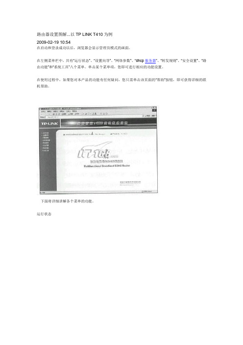
路由器设置图解...以TP LINK T410为例2009-02-19 10:54在启动和登录成功以后,浏览器会显示管理员模式的画面。
在左侧菜单栏中,共有“运行状态”、“设置向导”、“网络参数”、“dhcp服务器”、“转发规则”、“安全设置”、“路由功能”和“系统工具”八个菜单。
单击某个菜单项,您即可进行相应的功能设置。
在使用过程中,如果您对本产品的功能有任何疑问,您只需单击该页面的“帮助”按钮,即可获得详细的联机帮助。
下面将详细讲解各个菜单的功能。
运行状态本页显示路由器工作状态1)lan口状态此处显示当前lan口的mac地址、ip地址和子网掩码。
2)wan口状态此处显示当前wan口的mac地址、ip地址、子网掩码、网关和dns服务器。
同时右侧将显示用户上网方式(pppoe/动态ip/静态ip)。
如果用户的上网方式为pppoe(adsl拨号上网)的话,当用户已经连接internet 时,此处将会显示用户的上网时间和“断线”按钮,单击此按钮可以进行即时的断线操作,当用户尚未连接internet时,此处将会显示“连接”按钮,单击此按钮可以进行即时的连接操作。
3) wan口流量统计此处显示当前wan口接收和发送的数据流量信息。
网络参数在“网络参数”菜单下面,共有“lan口设置”、“wan口设置”和“mac地址克隆”三个子项。
单击某个子项,您即可进行相应的功能设置,下面将详细讲解各子项的功能。
LAN口设置本页设置lan口的基本网络参数。
1mac地址:本路由器对局域网的mac地址,此值不可更改。
2ip地址:本路由器对局域网的ip地址。
该ip地址出厂设置为192.168.1.1,您可以根据需要改变它。
ATTENTION:如果您改变了本ip地址,您必须用新的ip地址才能登录路由器进行web界面管理,并且局域网中所有计算机的默认网关必须设置为该ip地址才能正常上网。
3子网掩码:本路由器对局域网的子网掩码,可以在下拉列表中选择b类(255.255.0.0)或c类(255.255.255.0)地址的子网掩码。
TP10

接线图
二线式
三线式
PT100温度传感器 TP10系列
原理,结构
TP10包含一个PT100探头, PT100阻值会随温度变化而变化, PT100有二线 式, 三线式, 四线式几种规格可供选择.
特点
安装简单,多种量程可选,多种规格探头可选,全不锈钢外壳,结构紧凑 坚固。并可选配柜装式控制表。
应用
气液两用型,可用于供水系统,液压、气动系统,冷却系统,加热系统, 空调系统,自动化工程等。
上海百纳控制工程技术有限公司 E-mail:sales@
TP10.2/2 2
量程0…100℃
量程0…120℃
量程0…150℃
量程0…200℃
/6
探头直径为Ø6
/8
探头直径为Ø8
/ 25
探头长L为25mm
/ 50
探头长L为50mm
/ 75
探头长L为75mm
/ 100
探头长L为100mm
H 外螺纹连接
上海百纳控制工程技术有限公司 E-mail:sales@
TP10.1/2 1
温度
PT100温度传感器 TP10系列
选配附件2--DD001数显控制表
显示控制表 DT001: 该显示控制表与TP10系列PT100温度传感 器配合使用,作用是对温度值进行显示、控制。并可按设定值 输出开关量报警信号。
特点:
● 四位LED数字显示
● 输入规格: J, K,S,T,E,B,R,N,C,DIN-PT100
技术参数
△测量范围:
-50…0℃, -50…50 °C; 0...50 °C; 0...80 °C; 0...100 °C; 0...120°C, 0...150°C, 0...200°C,
2020年海康威视数字科技(中国)有限公司产品说明书

2020Hangzhou Hikvision Digital Technology Co.,Ltd.All rights reserved.About this ManualThe Manual includes instruc�ons for using and managing the Product.Pictures,charts,images and all other informa�on hereina�er are for descrip�on and explana�on only.The informa�on contained in the Manual is subject to change,without no�ce,due to firmware updates or other reasons.Please find the latest version of this Manual at the Hikvision website (h�ps:///).Please use this Manual with the guidance and assistance of professionals trained in suppor�ng the Product.Trademarksand other Hikvision's trademarks and logos are the proper�es of Hikvision in variousjurisdic�ons.Other trademarks and logos men�oned are the proper�es of their respec�ve owners.DisclaimerTO THE MAXIMUM EXTENT PERMITTED BY APPLICABLE LAW,THIS MANUAL AND THE PRODUCT DESCRIBED,WITH ITS HARDWARE,SOFTWARE AND FIRMWARE,ARE PROVIDED “AS IS”AND “WITH ALL FAULTS AND ERRORS”.HIKVISION MAKES NO WARRANTIES,EXPRESS OR IMPLIED,INCLUDING WITHOUT LIMITATION,MERCHANTABILITY,SATISFACTORY QUALITY,OR FITNESS FOR A PARTICULAR PURPOSE.THE USE OF THE PRODUCT BY YOU IS AT YOUR OWN RISK.IN NO EVENT WILL HIKVISION BE LIABLE TO YOU FOR ANY SPECIAL,CONSEQUENTIAL,INCIDENTAL,OR INDIRECT DAMAGES,INCLUDING,AMONG OTHERS,DAMAGES FOR LOSS OF BUSINESS PROFITS,BUSINESS INTERRUPTION,OR LOSS OF DATA,CORRUPTION OF SYSTEMS,OR LOSS OF DOCUMENTATION,WHETHER BASED ON BREACH OF CONTRACT,TORT (INCLUDINGNEGLIGENCE),PRODUCT LIABILITY,OR OTHERWISE,IN CONNECTION WITH THE USE OF THE PRODUCT,EVEN IF HIKVISION HAS BEEN ADVISED OF THE POSSIBILITY OF SUCH DAMAGES OR LOSS.YOU ACKNOWLEDGE THAT THE NATURE OF INTERNET PROVIDES FOR INHERENT SECURITY RISKS,AND HIKVISION SHALL NOT TAKE ANY RESPONSIBILITIES FOR ABNORMAL OPERATION,PRIVACY LEAKAGE OR OTHER DAMAGES RESULTING FROM CYBER-ATTACK,HACKER ATTACK,VIRUS INFECTION,OR OTHER INTERNET SECURITY RISKS;HOWEVER,HIKVISION WILL PROVIDE TIMELY TECHNICAL SUPPORT IF REQUIRED.YOU AGREE TO USE THIS PRODUCT IN COMPLIANCE WITH ALL APPLICABLE LAWS,AND YOU ARE SOLELY RESPONSIBLE FOR ENSURING THAT YOUR USE CONFORMS TO THE APPLICABLE LAW.ESPECIALLY,YOU ARE RESPONSIBLE,FOR USING THIS PRODUCT IN A MANNER THAT DOES NOT INFRINGE ON THE RIGHTS OF THIRD PARTIES,INCLUDING WITHOUT LIMITATION,RIGHTS OF PUBLICITY,INTELLECTUAL PROPERTY RIGHTS,OR DATA PROTECTION AND OTHER PRIVACYRIGHTS.YOU SHALL NOT USE THIS PRODUCT FOR ANY PROHIBITED END-USES,INCLUDING THE DEVELOPMENT OR PRODUCTION OF WEAPONS OF MASS DESTRUCTION,THE DEVELOPMENT OR PRODUCTION OF CHEMICAL OR BIOLOGICAL WEAPONS,ANY ACTIVITIES IN THE CONTEXT RELATED TO ANY NUCLEAR EXPLOSIVE OR UNSAFE NUCLEAR FUEL-CYCLE,OR IN SUPPORT OF HUMAN RIGHTS ABUSES.IN THE EVENT OF ANY CONFLICTS BETWEEN THIS MANUAL AND THE APPLICABLE LAW,THE LATER PREVAILS.Data Protec�onDuring the use of device,personal data will be collected,stored and processed.To protect data,the development of Hikvision devices incorporates privacy by design principles.For example,for device with facial recogni�on features,biometrics data is stored in your device with encryp�on method;for fingerprint device,only fingerprint template will be saved,which is impossible to reconstruct a fingerprint image.As data controller,you are advised to collect,store,process and transfer data in accordance with the applicable data protec�on laws and regula�ons,including without limita�on,conduc�ng security controls to safeguard personal data,such as,implemen�ng reasonable administra�ve and physical security controls,conduct periodic reviews and assessments of the effec�veness of your security controls.Scan the QR code to get the user manual for detailed informa�on.When connec�ng door contact and exit bu�on,the device and the RS-485card reader should use the same common ground connec�on.The Wiegand terminal here is a Wiegand input terminal.You should set the device’s Wiegand direc�on to “input”.If you should connect to an access controller,you should set theWiegand direc�on to “Output”.For details,see the user manual.The suggested external power supply for door lock is 12V,1AThe suggested external power supply for Wiegand card reader is 12V,1AFor wiring the fire system see the user manul.Do not wire the device to the electric supply directly.Door ContactIR LightIR LightUSB InterfaceWhite LightCameraScreenCard Presen�ng Area Fingerprint ScannerThe figures are for reference only.Debugging Port(For debugging only)Power Interface Wiring TerminalPSAM Card Slot (Reserved)SIM Card Slot (Reserved)Dimension:BacklightDirect SunlightDirect Sunlight through WindowIndirect Sunlight through WindowClose to Light Installa�on Environment:Indoor and outdoor installa�on are supported.if installing the device indoors,the device should be at least 2meters away from the light,and at least 3meters away from the window or the door.If installing the device outdoors,you should apply Silicone sealant among the cable wiring area to keep the raindrop from entering.Make sure the environment illumina�on is more than 100Lux.Before you start:According to the baseline on the moun�ng template,s�ck the moun�ng template on the wall or other surface,1.4meters higher than the ground.Make sure the output of external power supply fulfils LPS.Steps:Drill holes on the wall or other surface according to the moun�ng template and install the gang e two supplied screws(4_KA4x22-SUS)to secure the moun�ng plate on the gang e another four supplied screws to secure the moun�ng plate on the wall.Route the cables through the cable hole of the moun�ng plate,and connect to the corresponding external device’s cables.Apply Silicone sealant among the cable wiring area to keep the raindrop from entering.Insert the fingerprint module to the holes at the bo�om of the main part.Align the device with the moun�ng plate and hang the terminal on the moun�ng plate.Make sure the two sheets on each side of the mount plate have been in the holes at the back of the device.Use two supplied screws (SC-M4x12TP10-SUS)to secure the device and the moun�ng plate.After installation,for the proper use of the device (outdoor use),stick the protection film (parts of models supplied)on the screen.The installa�on height here is the recommended height.You can change it according to your actual needs.You can also install the device on the wall or other places without the gang box.For details,refer to the User Manual.For easy installa�on,drill holes on moun�ng surface according to the supplied moun�ng template.You should purchase the gang box separately.Apply Silicone SealantUse only power supplies listed in the user instruc�ons:Model ManufacturerStandard C2000IC12.0-24P-DE MOSO Power Supply Technology Co.,Ltd CEE C2000IC12.0-24P-GB MOSO Power Supply Technology Co.,Ltd BS ADS-24S-121224GPG Shenzhen Honor Electronic Co.,LtdCEENetwork InterfaceGND87mm196.8mmMoun�ng TemplateDatum2006/66/EC This with standards 2014/30/EU,WarningIn the use of regula�onsdirect STRONG PASSWORD We highly 3.Set fingerprint contents on picture is picture.save icon。
TP中图分类号.doc
TP中图分类号TP 自动化技术、计算机技术[TP-9] 自动化技术经济TP1 自动化基础理论TP11 自动化系统理论TP13 自动控制理论TP14 自动信息理论TP15 自动模拟理论(自动仿真理论)TP17 开关电路理论TP18 人工智能理论TP181 自动推理、机器学习TP182 专家系统、知识工程TP183 人工神经网络与计算TP2 自动化技术及设备TP20 一般性问题TP202 设计、性能分析与综合TP202+.1 可靠性、稳定性、寿命TP202+.2 精确性、误差TP202+.3 灵敏度TP202+.4 随机过程、随机信号TP202+.5 过渡过程TP202+.7 最佳化、自适应性TP203 结构、构造TP204 材料TP205 制造、装配、改装TP206 调整、测试TP206+.1 试验、测试技术与方法TP206+.3 故障预测、诊断与排除TP207 检修、维护TP21/27 各种自动化元件、部件、装置、系统 TP21 自动化元件、部件TP211 一般自动化元件、部件TP211+.1 无触点元件、部件TP211+.2 机械元件、部件TP211+.3 流体元件、部件TP211+.31 液压元件、部件TP211+.32 气压元件、部件TP211+.4 机电元件、部件TP211+.5 电子元件、部件TP211+.51 半导体元件、部件TP211+.53 磁性元件、部件TP211+.6 光电元件、部件TP211+.7 射线元件、部件TP212/217 各种自动化器件、自动化仪表TP212 发送器(变换器)、传感器TP212.1 物理传感器TP212.13 磁性传感器TP212.14 光传感器TP212.2 化学传感器TP212.3 生物传感器、医学传感器TP212.6 智能化传感器TP212.9 传感器的应用TP213 分配器、配电器TP214 调节器、调节阀TP214+.1 线性调节器TP214+.2 非线性调节器TP214+.3 比例调节器(有差调节器) TP214+.4 积分调节器(无差调节器) TP214+.5 比例积分调节器TP214+.6 比例微分调节器TP214+.7 程序调节器TP214+.8 最佳调节器TP214+.9 极值调节器TP215 传动装置(执行机构)TP216 自动检测仪器、仪表TP216+.1 自动测量仪表TP216+.2 自动记录和指示仪表TP216+.3 自动分析器TP216+.4 计算仪器TP217 校正元件、校正装置TP217+.1 无源校正元件TP217+.2 交流校正元件TP217+.3 有源校正元件TP23 自动化装置与设备TP24 机器人技术TP241 机械手TP241.2 工业机械手TP241.3 专用机械手TP242 机器人TP242.2 工业机器人TP242.3 专用机器人TP242.6 智能机器人TP242.6+1 机器人触觉TP242.6+2 机器人视觉TP242.6+3 机器人听觉TP242.6+4 机器人嗅觉TP249 应用TP27 自动化系统TP271 一般自动化系统TP271+.1 无触点系统TP271+.2 机械系统TP271+.3 流体系统TP271+.31 液压系统TP271+.5 电子系统TP271+.6 连续系统TP271+.61 连续线性系统TP271+.62 连续非线性系统TP271+.7 变参数系统TP271+.71 线性变参数系统TP271+.72 非线性变参数系统TP271+.73 断续变参数系统TP271+.74 随机变参数系统TP271+.8 不连续(离散、断续)系统TP271+.81 采样(脉冲)系统TP271+.82 数字和程序系统TP271+.83 继电器系统TP271+.9 反馈系统TP272/278 各种自动化系统TP272 自动调节、自动调节系统TP273 自动控制、自动控制系统TP273+.1 最佳控制、最佳控制系统TP273+.2 自适应(自整定)控制、自适应控制(自整定)系统 TP273+.21 特性自适应控制系统TP273+.22 学习控制系统、自行组织系统TP273+.23 极值系统(自寻最佳系统)TP273+.24 自整定系统TP273+.3 复合控制、复合控制系统TP273+.4 模糊控制、模糊控制系统TP273+.5 计算机控制、计算机控制系统TP274 数据处理、数据处理系统TP274+.1 自动记录和指示系统TP274+.2 数据收集和处理系统TP274+.3 自动分类与质量检查系统TP274+.4 集中检测与巡回检测系统TP274+.5 采用各种新技术的自动检测系统TP274+.51 放射线检测及其设备TP274+.52 红外线检测及其设备TP274+.53 超声波检测及其设备TP275 自动随动、自动随动系统TP276 自动拖动、自动拖动系统TP277 监视、报警、故障诊断系统TP278 自动生产作业线TP29 自动化技术在各方面的应用TP3 计算技术、计算机技术TP3-0 计算机理论与方法TP3-05 计算机与其他学科的关系TP30 一般性问题TP301 理论、方法TP301.1 自动机理论TP301.2 形式语言理论TP301.6 算法理论TP302 设计与性能分析TP302.1 总体设计、系统设计TP302.2 逻辑设计TP302.4 制图TP302.7 性能分析、功能分析TP302.8 容错技术TP303 总体结构、系统结构TP303+.1 元件TP303+.2 插件、机架TP303+.3 电源系统TP304 材料TP305 制造、装配、改装TP305+.1 微小型化工艺TP305+.2 防潮、防霉、防腐工艺TP306 调整、测试、校验TP306+.2 调整、测试方法TP306+.3 故障诊断与排除TP307 检修、维护TP308 机房TP309 安全保密TP309.1 计算机设备安全TP309.2 数据安全TP309.3 数据备份与恢复TP309.5 计算机病毒与防治TP309.7 加密与解密TP31 计算机软件TP311 程序设计、软件工程TP311.1 程序设计TP311.11 程序设计方法TP311.12 数据结构TP311.13 数据库理论与系统TP311.131 数据库理论TP311.132 数据库系统:按类型分TP311.132.1 层次数据库TP311.132.2 网状数据库TP311.132.3 关系数据库TP311.132.4 面向对象的数据库TP311.133.1 分布式数据库TP311.133.2 并行数据库TP311.134.1 模糊数据库TP311.134.3 多媒体数据库TP311.135.1 文献型数据库TP311.135.3 事实型数据库TP311.135.4 超文本数据库TP311.138 数据库系统:按系统名称分 TP311.5 软件工程TP311.53 软件维护TP311.54 软件移植TP311.56 软件工具、工具软件TP312 程序语言、算法语言TP313 汇编程序TP314 编译程序、解释程序TP315 管理程序、管理系统TP316 操作系统TP316.1/.5 操作系统:按类型分TP316.1 分时操作系统TP316.2 实时操作系统TP316.3 批处理TP316.4 分布式操作系统、并行式操作系统 TP316.5 多媒体操作系统TP316.6/.8 操作系统:按名称分TP316.6 DOS操作系统TP316.7 Windows操作系统TP316.8 网络操作系统TP316.81 UNIX操作系统TP316.82 XENIX操作系统TP316.83 NOVELL操作系统TP316.84 OS/2操作系统TP316.86 WindowsNT操作系统TP316.89 其他TP316.9 中文操作系统TP317 程序包(应用软件)TP317.1 办公自动化系统TP317.2 文字处理软件TP317.3 表处理软件TP317.4 图像处理软件TP319 专用应用软件TP32 一般计算器和计算机TP321 非电子计算机TP321+.1 求积仪、曲线仪TP321+.2 积分器TP321+.21 机械积分器TP321+.22 液压积分器TP321+.23 气压积分器TP321+.24 电气、机电积分器TP321+.3 手动计算机TP321+.5 电动计算机TP322 分析计算机(穿孔卡片计算机)TP322+.1 穿孔机TP322+.2 验孔机TP322+.3 分类机TP322+.5 制表机TP323 电子计算器TP33/38 各种电子计算机TP33 电子数字计算机(不连续作用电子计算机) TP331 基本电路TP331.1 逻辑电路TP331.1+1 集成化逻辑电路TP331.1+3 金属-氧化物-半导体管逻辑电路 TP331.2 数字电路TP332 运算器和控制器(CPU)TP332.1 逻辑部件TP332.1+1 寄存器TP332.1+2 计数器TP332.2 运算器TP332.2+1 加、减法器TP332.2+2 乘、除法器TP332.3 控制器、控制台TP333 存贮器TP333.1 内存贮器(主存贮器)总论TP333.2 外存贮器(辅助存贮器)总论TP333.3 磁存贮器及其驱动器TP333.3+1 磁芯存贮器TP333.3+11 单孔磁芯存贮器TP333.3+12 多孔磁芯存贮器TP333.3+2 磁薄膜存贮器TP333.3+21 平面磁薄膜存贮器TP333.3+3 磁泡存贮器TP333.3+4 磁鼓存贮器TP333.3+5 磁盘存贮器TP333.3+6 磁带存贮器TP333.3+7 电磁继电器存贮器TP333.4 光存贮器及其驱动器TP333.4+1 磁光存贮器TP333.4+2 全息存贮器TP333.4+3 激光存贮器TP333.5 半导体集成电路存贮器TP333.5+1 双极性型半导体存贮器TP333.5+2 金属-氧化物-半导体(MOS)存贮器 TP333.5+3 电荷耦合型存贮器TP333.6 超导体存贮器TP333.7 只读(ROM)存贮器TP333.8 随机存取存贮器TP333.93 交换器TP333.95 延迟线存贮器TP333.95+1 水银柱延迟线存贮器TP333.95+3 石英晶体延迟线存贮器TP333.95+5 磁滞伸缩延迟线存贮器TP333.96 虚拟存贮器TP334 外部设备TP334.2 输入设备TP334.2+1 图形输入设备TP334.2+2 图像输入设备TP334.2+3 文字与数字输入设备TP334.2+4 语音输入设备TP334.3 输出设备TP334.4 输入输出控制器[TP334.5] 外存储器TP334.7 接口装置、插件TP334.8 打印装置TP334.8+1 针式打印机TP334.8+2 热敏打印机TP334.8+3 喷墨打印机TP334.8+4 激光打印机TP334.8+8 各种用途打印机TP334.9 其他TP335 信息转换及其设备TP335+.1 模拟-数字转换设备TP335+.2 文字-代码转换设备TP335+.3 图形-代码转换设备TP335+.4 数字-模拟转换设备TP336 总线、通道TP337 仿真器TP338 各种电子数字计算机[TP338.1] 微型计算机TP338.2 小型计算机TP338.3 中型计算机TP338.4 大型、巨型计算机TP338.6 并行计算机TP338.7 阵列式计算机TP338.8 分布式计算机TP34 电子模拟计算机(连续作用电子计算机) TP342 运算放大器和控制器TP342+.1 运算放大器TP342+.2 运算器TP342+.21 加、减法器TP342+.22 乘、除法器TP342+.23 平方器、开方器TP342+.25 积分器、微分器TP342+.3 控制器TP343 存贮器TP344 输入器、输出器TP346 函数发生器TP347 延时器TP348 各种电子模拟计算机TP348+.1 微分分析器与增量计算机TP348+.2 直流电子模拟计算机TP352 数字-模拟计算机TP352+.1 数字微分分析器TP353 模拟-数字计算机TP36 微型计算机TP368 各种微型计算机TP368.1 微处理机TP368.2 单板微型计算机TP368.3 个人计算机TP368.32 笔记本计算机TP368.33 超微型计算机TP368.5 服务器、工作站TP368.6 网络计算机(NC)TP37 多媒体技术与多媒体计算机TP38 其他计算机TP381 激光计算机TP382 射流计算机TP383 超导计算机TP384 分子计算机TP387 第五代计算机TP389.1 人工神经网络计算机TP39 计算机的应用TP391 信息处理(信息加工)TP391.1 文字信息处理[TP391.11] 汉字信息编码TP391.12 汉字处理系统TP391.13 表格处理系统TP391.14 文字录入技术TP391.2 翻译机TP391.3 检索机TP391.4 模式识别与装置TP391.41 图像识别及其装置[TP391.42] 声音识别及其装置TP391.43 文字识别及其装置TP391.44 光模式识别及其装置TP391.5 诊断机TP391.6 教学机、学习机TP391.7 机器辅助技术TP391.72 机器辅助设计(CAD)、辅助制图 TP391.73 机器辅助技术制造(CAM)TP391.75 机器辅助计算(CAC)TP391.76 机器辅助测试(CAT)TP391.77 机器辅助分析(CAA)TP391.8 控制机TP391.9 计算机仿真TP392 各种专用数据库TP393 计算机网络TP393.0 一般性问题TP393.03 网络互连技术[TP393.04] 通信规程、通信协议[TP393.05] 网络设备TP393.06 计算机网络测试、运行TP393.07 计算机网络管理TP393.08 计算机网络安全TP393.09 计算机网络应用程序TP393.092 网络浏览器TP393.093 文件传送程序(FTP)TP393.094 远程登录(Telnet)TP393.098 电子邮件(E-mail)TP393.1/.4 各种计算机网TP393.1 局域网(LAN)、城域网(MAN)TP393.11 以太网TP393.12 令牌网TP393.13 DQDB网(分布队列双总线网络) TP393.14 FDDI网(高速光纤环网)TP393.15 ATM局域网[TP393.17] 无线局域网TP393.18 校园网、企业网(Intranet)TP393.2 广域网(WAN){TP393.3} 洲际网络TP393.4 国际互联网TP399 在其他方面的应用TP6 射流技术(流控技术)TP60 一般性问题TP601 理论、研究TP602 设计及性能分析TP602+.1 静态特性TP602+.2 动态特性TP603 结构、构造TP604 材料TP605 制造、装配TP606 调整、测试TP606+.1 静态测试TP606+.2 动态测试TP607 检修、维护TP61/67 各种射流装置TP61 射流元件TP61+1 有源射流元件TP61+2 无源射流元件TP61+3 数字射流元件(逻辑元件)TP61+3.1 附壁式射流元件TP61+3.2 紊流式射流元件(紊流放大器)TP61+3.3 动量交换式元件TP61+4 比例射流元件(模拟元件)TP61+4.1 对冲元件TP62 射流附件TP62+1 升压器TP62+2 转换器TP62+3 延时器TP62+4 抽负器TP63 检测发信装置TP64 执行机构TP65 动力源TP65+1 气源净化系统TP65+2 气源附件TP65+2.1 过滤器TP65+2.2 减压阀TP65+2.3 定值器TP66 射流控制线路TP67 射流自动控制系统TP69 射流技术的应用TP7 遥感技术TP70 一般性问题TP701 理论TP702 设计和性能分析TP703 结构TP704 材料TP705 制造、装配TP706 调整、测试TP707 检修、维护TP72/75 各种遥感及装置TP72 遥感方式TP721 依传感器接受信号的来源分 TP721.1 被动式遥感TP721.2 主动式遥感TP722 依探测的波长范围分TP722.3 紫外遥感TP722.4 可见光遥感TP722.5 红外遥感TP722.6 微波遥感TP73 探测仪器及系统TP731 多光谱扫描仪TP732 遥感传感器TP732.1 微波遥感传感器TP732.2 红外遥感传感器TP733 反束光导管摄像机TP75 遥感图像的解译、识别与处理 TP751 图像处理方法TP751.1 数字处理TP751.2 光学处理TP752 图像处理设备TP752.1 数字处理设备TP79 遥感技术的应用TP8 远动技术TP80 一般性问题TP801 理论、研究TP802 设计和性能分析TP802+.1 可靠性、稳定性、寿命TP802+.2 精确性、误差TP802+.3 灵敏度TP802+.4 远动信号、信号发射、接收及转换TP802+.5 作用距离TP802+.6 干扰(噪声)、抗干扰TP802+.7 最佳化、自适应性TP802+.8 信道划分TP803 结构TP804 材料TP805 制造、装配TP806 调整、测试TP806+.1 试验、测试技术与方法TP806+.3 故障预测、诊断与排除TP807 检修、维护TP81/87 各种远动装置及系统[TP81] 远动元件、部件TP83 远动化装置TP84 远程信道TP84+1 有线信道TP84+2 无线电中继信道TP87 远动化系统TP871 远距离调节、远距离调节系统TP872 远距离控制和信号、远距离控制和信号系统 TP872+.1 近作用的遥控系统TP872+.2 断续遥控系统TP872+.21 频率制TP872+.22 时间制TP872+.3 连续遥控系统TP872+.31 频率制TP872+.32 时间制TP872+.33 脉码制TP873 远距离测量、远距离测量系统TP873+.1 单路遥测系统TP873+.11 频率制TP873+.12 时间制TP873+.13 脉码制TP873+.14 增量制TP873+.2 多路遥测系统TP873+.21 频率划分制TP873+.22 时间划分制TP873+.23 脉码划分制TP89 远动技术在各方面的应用。
情绪相关脑电信号的特征选取与导联优化
情绪相关脑电信号的特征选取与导联优化李彤;王永宗;张艺耀;彭宏;朱玲玲;赵永岐【摘要】目的探究与情绪密切相关的脑电特征,并藉此优化最少导联集合.方法 30名被试观看四类典型情绪图片(轻松、沮丧、愉悦、恐惧)并记录脑电信号.Fisher分数(F-score)算法筛选每导联脑电特征,使用支持向量机方法(SVM)分类四种情绪.结果 24名被试情绪诱发有效,四个特征组合(β频带、γ频带、信息熵、微分熵)的F-score均值作为情绪有效性评价指标,筛选出分类准确率高达81.15%的5个导联(FT7、T7、FC4、TP10、O1).结论利用校正后的F-score算法首次筛选出脑电信号的特征组合,获得与情绪密切相关的最优导联集合,极大地降低了运算时间,该结果对实现情绪的快速识别有重要价值.【期刊名称】《安徽医科大学学报》【年(卷),期】2018(053)010【总页数】5页(P1517-1521)【关键词】情绪;情绪识别;脑电信号;特征选取;F-score【作者】李彤;王永宗;张艺耀;彭宏;朱玲玲;赵永岐【作者单位】安徽医科大学研究生院,合肥230032;军事医学研究院军事认知与脑科学研究所,军事认知与应激医学实验室,北京 100850;兰州大学信息科学与工程学院,甘肃省可穿戴装备重点实验室,兰州730000;中国人民解放军空军总医院特诊科,北京100042;兰州大学信息科学与工程学院,甘肃省可穿戴装备重点实验室,兰州730000;军事医学研究院军事认知与脑科学研究所,军事认知与应激医学实验室,北京 100850;安徽医科大学研究生院,合肥230032;军事医学研究院军事认知与脑科学研究所,军事认知与应激医学实验室,北京 100850【正文语种】中文【中图分类】R318近年来,脑电(electroencephalogram, EEG)以其低伪装性及较高时间分辨率在情绪识别领域中脱颖而出。
研究[1]表明,EEG高频成分可以反映人的情绪和认知状态,其中γ和β频带比低频频带能更好地区分情绪状态的转换[2]。
幕墙外装成本分析与管理
幕墙外装成本分析与管理目前建筑幕墙使用越来越广泛,变化多样,根据自身工程经验对建筑幕墙成本进行的初步探讨,希望对幕墙外装成本管理工作有所裨益。
本文材料价格仅供参考。
一、玻璃幕墙01 玻璃幕墙分类玻璃幕墙常用大致分为明框玻璃幕墙、隐框玻璃幕墙、半隐框玻璃幕墙、点式玻璃幕墙、全波玻璃幕墙等;龙骨大致分为钢龙骨与铝龙骨等。
02 玻璃幕墙成本构成普通玻璃幕墙综合单价约700~1000元/㎡,根据玻璃种类及厚度、幕墙系列不一样,单价升降幅度较大。
如******外装项目,铝龙骨TP8mm中等透光热反射镀膜玻璃幕墙综合单价:809元/㎡;铝龙骨内衬3mm厚穿孔铝单板+TP8mm中等透光热反射镀膜玻璃幕墙综合单价:1084元/㎡。
****商业楼外装工程,TP19mm厚超白玻璃全玻璃幕墙综合单价:955元/㎡;单、双色TP8(LOW-E)+12A+TP8中空彩釉玻璃隐框玻璃幕墙综合单价:823元/㎡;异形TP10+1.52PVB+TP10mm厚夹胶彩釉玻璃点式玻璃幕墙:1917元/㎡;一般玻璃幕墙成本构成,如******外装工程:玻璃占比约10%;型材占比约39%;制作及安装占比约21%;五金件、工程胶等其他材料费占比约10%,管理、利润、规费及税费合计约占比20%。
******外装工程采用单片镀膜玻璃,如采用中空玻璃、超白玻璃、彩釉玻璃等,玻璃等成本会有所变化。
03 玻璃主材成本分析玻璃主材受品牌、品种、规格等因素影响,尽量提高玻璃原片的利用率,常规玻璃规格为:2440*3300、2440*3660、2100*3300、2100*3660。
-玻璃分类-钢化玻璃钢化玻璃破碎后成小颗粒,属于安全玻璃,但可能会自爆(自爆率为3‰),为使钢化玻璃降低自爆率,一般要做均质处理将钢化玻璃加热到290±10℃,并保温一定时间,促使在钢化玻璃中的硫化镍完成晶相转变,让原本使用后可能自爆的钢化玻璃人为地提前破碎在工厂中,从而降低出厂钢化玻璃的自爆率,处理后自爆率约1‰,成本约增3元/mm/m2。
- 1、下载文档前请自行甄别文档内容的完整性,平台不提供额外的编辑、内容补充、找答案等附加服务。
- 2、"仅部分预览"的文档,不可在线预览部分如存在完整性等问题,可反馈申请退款(可完整预览的文档不适用该条件!)。
- 3、如文档侵犯您的权益,请联系客服反馈,我们会尽快为您处理(人工客服工作时间:9:00-18:30)。
JDBC驱动 5-4
使用纯Java方式连接数据库
由JDBC驱动直接访问数据库 优点:100% Java,快又可跨平台 缺点:访问不同的数据库需要下载专用的JDBC驱动
Java 应用程序
JDBC API
JDBC 驱动
DB Server
JDBC驱动 5-5
… Connection conn = null; 加载驱动 try { Class.forName("com.microsoft.sqlserver.jdbc.SQLServerDriver"); } catch (ClassNotFoundException e) { 必须进行相关异常处理 logger.error(e); 建立连接 } try { conn = DriverManager.getConnection( "jdbc:sqlserver://localhost:1433;DatabaseName=epet", "jbit", "bdqn"); System.out.println("建立连接成功!"); } catch (SQLException e) { logger.error(e); } finally { 关闭连接 try { conn.close(); } catch (SQLException e) { logger.error(e); } 演示示例:使用纯Java方式连接数据库 }
JDBC驱动 5-3
… 使用JDBC-ODBC进行桥连 Connection conn = null; 加载驱动 try { 配置数据源:控制面板ODBC数据源系统DSN Class.forName("sun.jdbc.odbc.JdbcOdbcDriver"); } catch (ClassNotFoundException e) { 编程 必须进行相关异常处理 logger.error(e); 建立连接 } try { conn = DriverManager.getConnection("jdbc:odbc:ConnSQLServer", "jbit", "bdqn"); System.out.println("建立连接成功!"); } catch (SQLException e) { logger.error(e); } finally { 关闭连接 try { conn.close(); } catch (SQLException e) { logger.error(e); } }
JDBC驱动 5-2
使用JDBC-ODBC桥方式连接数据库
将对JDBC API的调用,转换为对另一组数据库连接API的调用 优点:可以访问所有ODBC可以访问的数据库 缺点:执行效率低、功能不够强大
DB Server Java 应用程序
JDBC API
JDBC-ODBC桥
ODBC API
ODBC层
共性问题集中讲解
常见调试问题及解决办法 代码规范问题
JDBC应用
对宠物和主人信息进行管理:
宠物和主人信息存储在SQL Server 2008中 通过JDBC对宠物和主人进行增、删、改、查
字段名 字段说明
id name 序号 昵称
字段类型
int varchar(12)
其 他
主键、自增
health
提供者:数据库厂商 作用:负责连接各种不同的数据库
JDBC API
JDBC API可做三件事:与数据库建立连接、执行SQL 语句、处理结果
Connection
2 4
数据库服务器
Байду номын сангаас
3
客户端
Statement ResultSet
DriverManager
1
DriverManager :依据数据库的不同,管理JDBC驱动 Connection :负责连接数据库并担任传送数据的任务 Statement :由 Connection 产生、负责执行SQL语句 ResultSet:负责保存Statement执行后所产生的查询结果
第十章
JDBC
回顾与作业点评
Collection 、List 、Set 、Map接口的联系和 区别有哪些? ArrayList和LinkedList有什么异同之处?
有哪些遍历集合的方法? 为什么要引入泛型集合?
预习检查
JDBC的英文全称是什么? JDBC的主要作用是什么? PreparedStatement与Statement相比,具有 什么优势?
Statement常用方法
方法名
ResultSet executeQuery(String sql) int executeUpdate(String sql) boolean execute(String sql)
JDBC工作模板
加载JDBC驱动 try { Class.forName(JDBC驱动类); } catch (ClassNotFoundException e) { System.out.println("无法找到驱动类"); 与数据库建立连接 } try { Connection con=DriverManager.getConnection(JDBC URL,数据库用户名,密码); JDBC URL用来标识数据库 Statement stmt = con.createStatement(); ResultSet rs = stmt.executeQuery("SELECT a, b, c FROM Table1"); 发送SQL语句, while (rs.next()) { 并得到返回结果 int x = rs.getInt("a"); String s = rs.getString("b"); float f = rs.getFloat("c"); } 处理返回结果 con.close(); } catch (SQLException e) { 释放资源 e.printStackTrace(); }
使用Statement更新宠物
声明Statement变量 Connection conn = null; Statement stmt = null; … // 建立连接 conn = DriverManager.getConnection( "jdbc:sqlserver://localhost:1433;DatabaseName=epet", "jbit", "bdqn"); 获取Statement对象 // 更新狗狗信息到数据库 stmt = conn.createStatement(); stmt.executeUpdate("update dog set health=80,love=15 where id=1");
JDBC驱动 5-1
JDBC驱动由数据库厂商提供
在个人开发与测试中,可以使用JDBC-ODBC桥连方式 在生产型开发中,推荐使用纯Java驱动方式
Java 应用程序 JDBC API JDBC Driver Manager JDBC–ODBC桥 ODBC 纯Java 驱动
DB Server
DB Server
JDBC是Java数据库连接技术的简称,提供连接 各种常用数据库的能力
Java应用程序 JDBC 客户端 JSP/Servlet JDBC 客户端 数据库服务器
应用服务器
数据库服务器
JDBC程序的工作原理
Java 应用程序
JDBC API
提供者:Sun公司 内容:供程序员调用的接口与类,集成 在java.sql和javax.sql包中,如:
练习——使用纯Java方式连接数据库
需求说明:
数据库为SQL Server 2008 数据库名“epet”,用户名“jbit”,密码“bdqn” 使用纯Java方式连接该数据库 如果连接成功,输出“建立连接成功!”,否则 输出“建立连接失败!” 进行相关异常处理
完成时间:20分钟
共性问题集中讲解
DriverManager类 Connection接口 Statement接口 ResultSet接口
JDBC API JDBC Driver Manager
JDBC 驱动
JDBC 驱动
DriverManager
提供者:Sun公司 作用:管理各种不同的JDBC驱动
Sql Server
Oracle
JDBC 驱动
love strain
健康值
亲密度 品种
int
int varchar(20) id
字段名
字段说明
序号 姓名 密码 元宝数
字段类型
int varchar(12) varchar(20) int
其 他
主键、自增
name password money
使用Statement添加宠物
… 声明Statement变量 Connection conn = null; Statement stmt = null; … // 建立连接 conn = DriverManager.getConnection( "jdbc:sqlserver://localhost:1433;DatabaseName=epet", "jbit", "bdqn"); 获取Statement对象 // 插入狗狗信息到数据库 stmt = conn.createStatement(); StringBuffer sbSql = new StringBuffer( "insert into dog (name,health,love,strain) values ( '"); sbSql.append(name + "',"); sbSql.append(health + ","); 执行SQL语句 sbSql.append(love + ",'"); sbSql.append(strain + "')"); stmt.execute(sbSql.toString()); … 演示示例:使用Statement添加宠物 stmt.close(); conn.close(); 关闭Statement对象
