美国ODIS公司将开发单片红外成像与读出电路
2023年继续教育集成电路作业(八)
2023年继续教育作业(八)集成电路一、单选题(共3题,每题20分)1、按()来份,集成电路分为双极型和单极型。
答案: D、导电类型2、光生伏特效应是由()发现的。
答案: D、法国科学家贝克雷尔3、EMIB理念跟基于硅中介层的2.5D封装类似,是通过()进行局部高密度互连。
答案: C、硅片4、()是指的在材料结构、工艺品质和精度、可靠性以及稳定性等性能方面,达到了半导体设备及技术要求的零部件。
答案: B、半导体零部件5、从区域分布情况来看,我国集成电路企业()密度最高。
答案: C、长三角二、多选题(共5题,每题8分)1、芯片核心设备主要有()。
答案: D、芯片封测设备 E、晶圆制造设备2、韩国三星属于集成电路垂直整合制造厂,具备()全流程能力。
答案: A、设计 B、制造 C、封装测试3、2020年国务院出台的《新时期促进集成电路产业和软件产业高质量发展的若干政策》中明确提出,进一步优化集成电路产业和软件产业发展环境,深化产业国际合作,提升产业()。
答案: A、创新能力 C、发展质量4、在加工芯片的过程中,光刻机通过一系列的光源能量、形状控制手段,将光束透射过画着线路图的(),经物镜补偿各种光学误差,将线路图成比例()后映射到硅片上,然后使用()方法显影,得到刻在硅片上的电路图。
答案: A、掩模 B、缩小 C、化学5、就半导体工艺整体而言,()和()两个环节的技术壁垒极高。
答案: A、硅片制造 B、芯片制造三、判断题(共5题,每题6分)1、硬核是用硬件描述语言或软件编程语言描述的功能块。
答案:错误2、据掺杂杂质不同,我们把半导体可以分为N型半导体与P型半导体,P型半导体主要掺杂的是五价元素,如磷、砷等。
答案:错误3、集成电路产业在国民经济中的关键性和战略性作用日益凸显。
答案:正确4、整体来看,汽车芯片产业链的重点企业基本为国内企业,国外的领先企业数量不多。
答案:错误5、社会各界对维权援助机构的了解度较高。
IEEEStdC57.124-1991
IEEE Std C57.124-1991Reconized as an American National Standard (ANSI)IEEE Recommended Practice for theDetection of Partial Discharge and the Measurement of Apparent Charge inDry-Type TransformersSponsorTransformers Committeeof theIEEE Power Engineering SocietyApproved June 27, 1991Reaffirmed February 6, 1997Institute of Electrical and Electronics EngineersApproved October 11, 1991Reaffirmed September 19, 1996American National Standards InstituteAbstract: IEEE Std C57.124-1991 covers the detection of partial discharges occurring in the insulation of dry-type transformers of their components and the measurement of the associated apparent charge at the terminals when alternating test voltage is applied. The wideband method is used. The detection system and calibrator characteristics are described, and the test procedure is established.Keywords: Apparent charge, corona, cost coil transformers, dry-type transformers, partial discharge, ventilated dry-type transformersThe Institute of Electrical and Electronics Engineers, Inc.345 East 47th Street, New York, NY 10017-2394, USACopyright © 1992 byThe Institute of Electrical and Electronics Engineers, Inc.All rights reserved. Published 1992Printed in the United States of AmericaISBN 1-55937-159-5No part of this publication may be reproduced in any form, in an electronic retrieval system or otherwise, without the prior written permission of the publisher.IEEE Standards documents are developed within the Technical Committees of the IEEE Societies and the Standards Coordinating Committees of the IEEE Standards Board. Members of the committees serve voluntarily and without compensation. They are not necessarily members of the Institute. The standards developed within IEEE represent a consensus of the broad expertise on the subject within the Institute as well as those activities outside of IEEE that have expressed an interest in participating in the development of the standard.Use of an IEEE Standard is wholly voluntary. The existence of an IEEE Standard does not imply that there are no other ways to produce, test, measure, purchase, market, or provide other goods and services related to the scope of the IEEE Standard. Furthermore, the viewpoint expressed at the time a standard is approved and issued is subject to change brought about through developments in the state of the art and comments received from users of the standard. Every IEEE Standard is subjected to review at least every five years for revision or reaffirmation. When a document is more than five years old and has not been reaffirmed, it is reasonable to conclude that its contents, although still of some value, do not wholly reflect the present state of the art. Users are cautioned to check to determine that they have the latest edition of any IEEE Standard.Comments for revision of IEEE Standards are welcome from any interested party, regardless of membership affiliation with IEEE. Suggestions for changes in documents should be in the form of a proposed change of text, together with appropriate supporting comments.Interpretations: Occasionally questions may arise regarding the meaning of portions of standards as they relate to specific applications. When the need for interpretations is brought to the attention of IEEE, the Institute will initiate action to prepare appropriate responses. Since IEEE Standards represent a consensus of all concerned interests, it is important to ensure that any interpretation has also received the concurrence of a balance of interests. For this reason IEEE and the members of its technical committees are not able to provide an instant response to interpretation requests except in those cases where the matter has previously received formal consideration.Comments on standards and requests for interpretations should be addressed to:Secretary, IEEE Standards Board445 Hoes LaneP.O. Box 1331Piscataway, NJ 08855-1331USAIEEE Standards documents are adopted by the Institute of Electrical and Electronics Engineers without regard to whether their adoption may involve patents on articles, materials, or processes. Such adoption does not assume any liability to any patent owner, nor does it assume any obligation whatever to parties adopting the standards documents.Foreword(This foreword is not a part of IEEE Std C57.124-1991, IEEE Recommended Practice for the Detection of Partial Discharge and the Measurement of Apparent Charge in Dry-Type Transformers.)This recommended practice for measuring partial discharge of dry-type transformers was conceived for the purpose of establishing a standardized method for conducting partial discharge tests of dry-type transformers. The results of the tests may be compared with various transformer designs and manufacturers to establish a partial discharge limit for dry-type transformers.This recommended practice follows the format of IEEE Std 454, IEEE Recommended Practice for the Detection and Measurement of Partial Discharge (Corona) During Dielectric Tests, and IEEE Std C57.113, IEEE Guide for Partial Discharge Measurement in Liquid-Filled Power Transformers and Shunt Reactors. Sections on current detection were purposely omitted, as this technique is normally not used for dry-type transformers.There is no recognized definition of “partial discharge-free"”when referring to partial discharge inception voltage or extinction voltage. An arbitrary sensitivity of 10 pC is suggested until such time as a more definitive standard is established.Various specifications are already written specifying partial discharge-free transformers from 1.1 p.u. operating voltage to 2.0 p.u. operating voltage. It is the intent of this recommended practice to encourage manufacturers of dry-type transformers and users of dry-type transformers to investigate and report the results of factory tests and field experience of partial discharge in dry-type transformers. It is recognized that Paschen's Law applies to the partial discharge intensity and extinction voltage of dry-type transformers. It is conceivable that a dry-type transformer would test partial discharge-free at 1.65 p.u. voltage at room temperature and be barely partial discharge-free at operating temperature for a Class 220C. system. This correlation should be verified with field experience and reported.The guide specifies no particular discharge testing instruments and systems. Several commercially available units are being used. A measuring system of discreet components readily available has been used for measuring partial discharge. Most manufacturers' laboratories have partial discharge-free HV test sets and oscilloscopes. The only additional components required to complete the detection circuit are a partial discharge-free coupling capacitor composed of two 60 kV, .002 mfd capacitors in series, and an inductance composed of a coil of magnet wire. Calibration is accomplished using a calibrated square wave generator and a calibrated coupling capacitor of .0001 mfd.The following two test procedures are proposed:1)To test partial discharge between the coil and ground, normally accomplished during the applied voltage test.2)The test procedure takes place during the induced voltage test to detect partial discharge within a coil. It issuggested that partial discharge measurements be made in both modes. The partial discharge measurement may be made during the normal sequence of tests, while the applied and induced voltage tests are being made.An alternative sequence is to conduct the partial discharge test immediately following the applied voltage test and induced voltage test.The high-voltage bus bars of high-voltage transformers sometimes cause nondestructive partial discharge. This partial discharge in no way affects the reliability of the transformer coils. It may be necessary to disconnect the bus bar from the coils before conducting the partial discharge test on only the coils in order to test for partial discharge in the transformer coils. A note should be added to any test reports stating that the bus bar was removed for the test.At the time this document was submitted to the Standards Board, the Working Group on Recommended Practice for the Detection of Partial Discharges and the Measurement of Apparent Charge in Dry-Type Transformers had the following members:A.D. Kline, (Chairman)B. F. Allen Roy Bancroft D. A. Barnard A. Bimbiris M. Cambre O. R. Compton J. FrankE. Gearhart R. Hayes R. H. HollisterJ. W. HuppA.M. IversenA. J. JonnattiS. P. KennedyE. KoenigM. L. ManningR. A. MarekM. I. MitelmanJ. J. NayW. F. PattersonR. L. ProvostJ. RoddenV. ThenappanR. E. Uptegraff, Jr.G. H. VaillancourtH. J. WindischThe following persons were on the balloting committee that approved this document for submission to the IEEE Standards Board:E. J. Adolphsen L. C. Aicher D. J. AllanB. AllenR. Allustriarti M. S. Altman J. C. Arnold J. AubinR. Bancroft D. Barnard D. L. Basel P. L. Bellaschi S. Bennon W. B. Binder J. V. Bonucchi J. D. Borst C. V. Brown O. R. Compton F. W. Cook J. L. Corkran D. W. Crofts J. N. Davis D. J. Douglas R. F. Dudley J. C. Dutton J. K. Easley J. A. Ebert D. J. Fallon F. L. Foster M. Frydman H. E. Gabel R. E. Gearhart D. W. Gerlach D. A. Gillies R. S. Girgis R. L. GrubbF. J. GryszkiewiczG. HallJ. H. HarlowF. W. HeinrichsW. R. HenningD. R. HightonP. J. HoeflerC. HoeselR. H. HollisterC. C. HoneyE. HowellsC. HurryG. W. IliffY. P. IijimaR. G. JacobsenD.C. JohnsonD. L. JohnsonA. J. JonnattiC. P. KappelerR. B. KaufmanJ. J. KellyW. N. KennedyJ.P. KinneyB. KlaponskiA.D. KlineE. KoenigJ. G. LackeyR. E. LeeH.F. LightS.R. LindgrenL.W. LongL. A. LowdermilkR. I. LoweM. L. ManningH. B. MargolisT. MassoudaJ. W. MatthewsJ. McGillC. J. McMillenW. J. McNuttS. P. MehtaC. K. MillerC. H. MillianR. E. MinkwitzM. MitelmanH. R. MooreW. E. MorehartR. J. MuselW. H. MutschlerE. T. NortonR. A. OlssonB. K. PatelW. F. PattersonH. A. PearceD. PercoL. W. PierceJ. M. PollittC. P. RaymondC. A. RobbinsL. J. SavioW. E. SaxonD. N, SharmaV. ShenoyW. W. SteinL. R. StenslandD. SundinL. A. SwensonD. S. TakachV. ThenappanR. C. Thomas J. A. Thompson T. P. Traub D. E. Truax W. B. Uhl R. E. Uptegraff, Jr.G. H. VaillancourtA. VeitchL. B. WagenaarR. J. WheartyA. L. WilksW. E. WrennA. C. WurdackE. J. YasudaAt the time this recommended practice was published, it was under consideration for approval as an American National Standard. The Accredited Standards Committee on Transformers, Regulators, and Reactors, C57, had the following members at the time this document was sent to letter ballot:Leo J. Savio, ChairJohn A. Gauthier, SecretaryOrganization of Representative Electric Light and Power Group...............................................................................................P.E. OrehekS. M. A. RizviF. StevensJ. SullivanJ. C. ThompsonM.C. Mingoia (Alt.) Institute of Electrical and Electronics Engineers......................................................................J. D. BorstJ. DavisJ. H. HarlowL. SavioH. D. SmithR. A. VeitchNational Electrical Manufacturers Association........................................................................G. D. CoulterP. DeweverJ. D. DouglasA. A. GhafourianK. R. LinsleyR. L. PlasterH. RobinR. E. Uptegraff, Jr.P. J. Hopkinson (Alt.)J. Nay (Alt.) Tennessee Valley Authority.......................................................................................................F. A. Lewis Underwriters Laboratories, Inc.................................................................................................W. T. O'GradyUS Department of Agriculture, REA........................................................................................J. BohlkUS Department of Energy, Western Area Power Administration.............................................D. R. TorgersonUS Department of the Interior, Bureau of Reclamation............................................................F. W. Cook, Sr.US Department of the Navy, Civil Engineering Carps.............................................................H. P. StickleyWhen the IEEE Standards Board approved this standard on June 27, 1991, it had the following membership:Marco W. Migliaro, ChairDonald C. Loughry, Vice ChairAndrew G. Salem, SecretaryDennis BodsonPaul L. BorrillClyde CampJames M. Daly Donald C. Fleckenstein Jay Forster*David F. Franklin Ingrid Fromm Thomas L. HannanDonald N. HeirmanKenneth D. HendrixJohn W. HorchBen C. JohnsonIvor N. KnightJoseph Koepfinger*Irving KolodnyMichael A. LawlerJohn E. May, Jr.Lawrence V. McCAllT. Don Michael*Stig L. NilssonJohn L. RankineRonald H. ReimerGary S. RobinsonTerrance R. Whittemore*Member EmeritusAlso included are the following nonvoting IEEE Standards Board liaisons:Fernando Aldana Satish K. AggarwalJames Beall Richard B. EngelmanStanley Warshaw Deborah A. CzyzIEEE Standards Project EditorCLAUSE PAGE1. Scope (1)2. Purpose (1)3. References (1)4. Definitions (2)5. Partial Discharge Detection System (3)5.1High-Voltage Coupling Circuit (3)5.2Measuring Impedance Unit (Z m) (4)5.3Filter Characteristics (5)5.4Display Unit (5)5.5Discharge Meter (6)5.6Basic Sensitivity (6)5.7Partial Discharge Detector Basic Sensitivity Test (6)6. Calibrator Characteristics (6)6.1Calibrating Capacitor Value (C q) (7)6.2Pulse Generator Rise Time and Decay Time (7)6.3Pulse Generator Amplitude (U o) (7)6.4Pulse Generator Output Impedance (Z o) (7)6.5Calibrator Output Level Adjustment (7)6.6Pulse Generator Frequency (7)7. Tests (7)7.1General Requirements (7)7.2Conditioning (8)7.3Requirements for the Test Voltage (8)7.4Transformer Connections (8)7.5Significance of Various Test Connections (8)7.6Choice of Test Procedure (9)7.7Disturbances (10)8. Bibliography (18)Annex (informative) Partial Discharge Recognition (24)IEEE Recommended Practice for the Detection and the Measurement of Partial Discharge in Dry-Type Transformers1. ScopeThis recommended practice applies to the detection of partial discharges occurring in the insulation of dry-type transformers or their components, and to the measurement of the associated apparent charge at the terminals when an alternating test voltage is applied.2. PurposePartial discharge measurements in dry-type transformers may preferably be made on the basis of measurement of the apparent charge. Relevant measuring systems are classified as narrow-band or wide-band systems. Both systems are recognized and widely used. Without giving preference to one or the other, it is the object of this document to describe the wide-band method. General principles of partial discharge measurements, including the narrow-band method, are covered in IEEE Std 454-19731 [8]2, IEC 270 (1981) [6]3and IEC 76-3 (1980) [5].3. ReferencesThe following publications should be used in conjunction with this document. When the standards referred to in this guide are superseded by a new revision approved by the relevant standards authority, the latest revision should apply.[1] ANSI C68.1-1968, Standard for Measurement of Voltage In Dielectric Tests.41This standard has been withdrawn, however, copies are available from the Institute of Electrical and Electronics Engineers, Inc., Service Center, 445 Hoes Lane, Piscataway, N.J. 08855, U.S.A.2The numbers in brackets refer to those listed in Section 4.3IEC publications are available from IEC Sales Department, Case Postale 131, 3 rue de Varembé, CH 1211, Genève 20, Switzerland/Suisse. IEC publications are also available in the United States from the Sales Department, American National Standards Institute, 11 West 42nd Street, 13th Floor, New York, NY 10036, USA.4ANSI publications are available from the American National Standards Institute, 11 West 42nd Street, 13th Floor, New York, NY 10036.IEEE Std C57.124-1991IEEE RECOMMENDED PRACTICE FOR THE DETECTION OF PARTIAL DISCHARGE [2] ASTM D1868-81 (1990-E01), Method for Detection and Measurement of Partial Discharge (Corona) Pulses in Evaluation of Insulation Systems.5[3] ASTM STP-669, Engineering Dielectrics, Vol. 1, Corona Measurement and Interpretation.[4] CIGRE Working Group 21-03, "Recognition of Discharges," Electra, No. 11, pp. 61-98, Dec, 1969.6[5] IEC 76-3 (1980), Power Transformers, Part 3: Insulation Levels and Dielectric Tests.7[6] IEC 270 (1981), Partial Discharge Measurements.[7] IEEE Std 436-1991, IEEE Guide for Making Corona (Partial Discharge) Measurements of Electronics Transformers (ANSI).8[8] IEEE Std 454-1973, IEEE Recommended Practice for the Detection and Measurement of Partial Discharge (Corona) During Dielectric Tests.[9] IEEE Std C57.113-1991, IEEE Guide for Partial Discharge Measurement in Oil-Filled Power Transformers and Shunt Reactors (ANSI).4. Definitionspartial discharge: A partial discharge within the terms of this document is an electric discharge that only partially bridges the insulation between conductors. The term “corona ” has also been used frequently with this connotation. Such usage is imprecise and is gradually being discontinued in favor of the term “partial discharge.”apparent charge (terminal charge): The apparent charge (q) of a partial discharge is that charge which, if it could be injected instantaneously between the terminals of the test object, would momentarily change the voltage between its terminals by the same amount as the partial discharge itself. The apparent charge should not be confused with the charge transferred across the discharging cavity in the dielectric medium. Apparent charge within the terms of this document is expressed in coulombs, abbreviated C. One pC is equal to 10-12 coulombs.repetition rate(n).: The partial discharge pulse repetition rate (n) is the average number of partial discharge pulses per second measured over a selected period of time.acceptable terminal partial discharge level: The acceptable terminal partial discharge level is that specified maximum terminal partial discharge value for which measured terminal partial discharge values exceeding the said value are considered unacceptable. The method of measurement and the test voltage for a given test object should be specified with the acceptable terminal partial discharge level.voltage related to partial discharges: Voltage within the terms of this document is the phase-to-ground alternating voltage for applied tests (Fig 1) or terminal to terminal alternating voltage for induced voltage tests (Fig 8). Its value is expressed by its peak value divided by the square root of two.partial discharge inception voltage: The lowest voltage at which partial discharges exceeding a specified level are observed under specified conditions when the voltage applied to the test object is gradually increased from a lower value. This voltage is expressed as the peak value divided by the square root of two.5ASTM publications are available from the American Society for Testing and Materials, Customer Service Dept., 916 Race Street, Philadelphia, P.A. 19103, U.S. A.6CIGRE publications are available from the International Conference on Large-Voltage Electric Systems, 112 Boulevard Haussman, F-75008 Paris, France.7IEC publications are available from IEC Sales Department, Case Postale 131, 3 rue de Varembé, CH 1211, Genève 20, Switzerland/Suisse. IEC publications are also available in the United States from the Sales Department, American National Standards Institute, 11 West 42nd Street, 13th Floor, New York, NY 10036, USA.8IEEE publications are available from the Institute of Electrical and Electronics Engineers, Inc., Service Center, 445 Hoes Lane, Piscataway, N.J. 08855, U.S. A.partial discharge extinction voltage: The voltage at which partial discharges exceeding a specified level cease under specified conditions when the voltage is gradually decreased from a value exceeding the inception voltage. This voltage is expressed as the peak value divided by the square root of two.partial discharge-free test voltage: The partial discharge-free test voltage is a specified voltage, applied in accordance with a specified test procedure, at which the test object should not exhibit partial discharges above the acceptable energized background noise level.energized background noise level: The energized background noise level stated in pC is the residual response of the partial discharge measurement system to background noise of any nature after the test circuit has been calibrated and the test object is energized at a maximum of 50% of its nominal operating voltage.acceptable energized background noise level: The acceptable energized background noise level present during test should not exceed 50% of the acceptable terminal discharge level, and in any case, should be below 100 pC (5 pC if an acceptable terminal discharge level of 10 pC is required.)5. Partial Discharge Detection System(Figs 9 and 10 taken from ASTM STP669)The partial discharge detection system comprises the following components:1) a high-voltage coupling circuit (C1, C v)2) a measuring impedance unit (Z m consisting of R m, C2 and L)3)an amplifier and filter circuit4) a display unit5) a discharge meter6) a calibrator (C q, V l)7) a source filter (Z optional)5.1 High-Voltage Coupling CircuitThe purpose of the high-voltage coupling circuit is to allow the connection of the measuring impedance (Z m) to the high-voltage terminal of the transformer under test. In other types of high-voltage equipment, a single, low-capacitance high-voltage capacitor is usually used for this purpose, but in transformers, the equivalent terminal capacitance is usually very low, so a substantial amount of signal is normally produced by partial discharge of only a few pC, and measurement sensitivity is not a problem. At the same time, due to standing waves within the winding, a certain amount of signal cancellation may occur if the bandwidth is not sufficiently wide. Therefore, to insure that the input circuit of the partial discharge detection system does not act as a differentiator and reduce the total bandwidth of the system, it has been found that a high value for the coupling capacitor is necessary to produce a long-time constant of the input circuit. Even then, however, the low equivalent terminal capacitance of the transformer, usually less than 500 pF, will limit this time constant and it may not be possible to make it sufficiently long. Therefore, the use of a single coupling capacitor is not recommended. On the other hand, a satisfactory time constant can always be obtained by using a second capacitor (C2) as part of the measurement impedance, and this is the recommended method.As shown in Figs 9 and 10, high-voltage capacitor C1, and low-voltage capacitor C2, will form a voltage divider. This voltage divider will reduce the sensitivity of the measurement. To make sure that both the sensitivity is still sufficient and the time constant is sufficiently long, the values of C1, C2, and L should respect the conditions below:(1)≥C1100pF(2)where R m is the parallel resistive part of the measuring impedance unit (Z m ). The value of R m should be determined from the particular partial discharge instrument that is used.Example:For f L = 70kHz ,R m = 2.5k Ω and C 1 = 100pFA value of 1000 pF may be chosen for C 2 since 1000 pF ≥ 909 pF and (3)In cases where an RLC measurement impedance is used, the value of L should satisfy the equation below. This will ensure that the measurement bandwidth is unaffected by the presence of L .(4)If the transformer to be tested is fitted with a capacitive bushing tap, then this can be used directly as the high-voltage coupling circuit, and a separate coupling capacitor C 1 is not needed.5.2 Measuring Impedance Unit (Z m )The measuring impedance unit (Z m ) is located physically close to the high-voltage coupling circuit and serves two main purposes:1)It attenuates the test voltage present on the high-voltage coupling circuit to a safe value for measurement of partial discharge signals;2)It matches the amplifier and filter circuit to the high-voltage coupling circuit in insuring a fiat frequencyresponse across the full measurement bandwidth.The measuring impedance unit (Z m )should be configured in such a way as to permit test voltage level monitoring and to observe the phase relationship between the test voltage and the partial discharge pulses; this technique helps to identify the nature of the discharges.As shown in Figs 9 and 10, capacitor C v , whose capacitance value should be chosen to be at least 500 times that of C 1,may be placed in either one of the following two positions:1)In series with inductor L (Fig 9 or 10), or 2)In series with the low-voltage side of high-voltage capacitor C 1 (Fig 10.)C 212llf L R m -------------------≥C 216.28x 70000x 2500,----------------------------------------------909pF ==1000100-----------1015≤=L 25006.28x 70000,------------------------------- 5.7mH ==C 2C 1------15≤L R m 2llf L -----------≥Figure 9 shows the preferred position for C v since the input impedance of the display unit does not shunt the measurement impedance and can be neglected. However, some voltage will reach the input of the amplifier and filter circuit and may cause it to saturate. This voltage can be decreased by increasing the value of C v until it is less than 5V . If saturation occurs, a 20 nF low-voltage capacitor may be placed in series with the input of the amplifier and filter circuit as shown to decouple voltage at the excitation frequency.In the cases where one can not be absolutely certain that saturation of the amplifier will not occur, it is then advised to place C v in the position shown in Fig 10. The impedance of the display circuit will now shunt the measurement impedance and its input capacitance will need to be considered to calculate the value of C 2, as it will add to it.5.2.1 Lower and Upper Cut-Off Frequencies (f L and f H )The lower and upper cut-off frequencies f L and f H , respectively, are the frequencies at which the response to a constant sinesoidal input voltage has fallen by 6 db from the maximum value occurring inside the recommended bandwidth.f L should be located in the range from 70 to 120 kHz to minimize the effect of winding attenuation on partial discharge signals, and at the same time, to provide adequate rejection of SCR-generated noise present in manufacturing plants.An upper limit on f H of 300 kHz is usually necessary to prevent broadcast stations from interfering with the partial discharge measurement.5.3 Filter CharacteristicsThe filter characteristics of the partial discharge detection circuit should be such as to provide attenuation of at least 50db at 25 kHz, of at least 60 db at 15 kHz and below, and of at least 20 db at 500 kHz and above, with respect to the response at the geometric mean frequency (f C ) of the system pass bandwidth that is given by:The filter may be combined with an amplifier to form an active filter. Care should be taken to prevent the saturation of the filter input by the presence of the applied test voltage.5.3.1 Bandwidth ∆fThe bandwidth ∆f is defined as:∆f = f H − f LThe bandwidth should not be less than 100 kHz. A wider bandwidth provides a response whose level is less sensitive to the location of a partial discharge pulse along a transformer winding and is, therefore, more uniform. A bandwidth wider than 100 kHz is preferable, but may lead to background noise problems.5.3.2 LinearityThe instrument circuit, display unit, and discharge meter should be linear within plus or minus 10% of full scale in the range of 50 to 1000 pC.5.4 Display UnitThe display unit should be a cathode ray oscilloscope with a linear, rectangular, or an elliptical time-base. In all cases,the time-base should be synchronized to the test voltage, and at least 98% of a full cycle should be displayed. The phase relationship of the partial discharges to the test voltage should be easy to determine. A suitable graticule should be provided.f c f L f H •().5=。
《半导体制造过程的批间控制和性能监控》随笔

《半导体制造过程的批间控制和性能监控》读书札记目录一、内容描述 (2)1.1 背景介绍 (2)1.2 研究目的与意义 (3)二、半导体制造过程概述 (4)2.1 半导体制造流程 (6)2.2 每个阶段的工艺要点 (7)三、批间控制的重要性 (9)3.1 影响产品质量的因素 (10)3.2 如何实现有效的批间控制 (11)四、性能监控在半导体制造中的作用 (12)4.1 性能监控的定义与目的 (13)4.2 监控方法与技术 (15)五、批间控制和性能监控的策略与技术 (16)5.1 控制策略 (18)5.2 监控技术 (19)5.2.1 预测性维护 (21)5.2.2 实时监控系统 (22)六、实际案例分析 (23)6.1 国内外半导体制造企业的案例 (25)6.2 案例分析 (26)七、挑战与未来趋势 (27)7.1 当前面临的挑战 (28)7.2 未来发展趋势与展望 (30)八、结论 (31)8.1 研究成果总结 (33)8.2 对未来研究的建议 (33)一、内容描述《半导体制造过程的批间控制和性能监控》是一本深入探讨半导体制造领域中质量控制与性能监测的重要著作。
本书通过对半导体制造过程的全面剖析,揭示了批间控制的关键性和性能监控的重要性。
本书共分为七个章节,详细阐述了半导体制造过程中从原材料到最终产品的全方位控制策略。
“批间控制”主要介绍了如何在生产过程中确保产品质量的一致性和稳定性,通过精确的工艺参数控制、严格的质量检测以及有效的设备维护,实现了对制造过程的全面监控和管理。
“性能监控”则侧重于评估半导体产品的性能指标,包括电学性能、光学性能和机械性能等,并通过实时数据采集和分析,及时发现潜在问题并采取相应措施,确保产品在满足性能要求的同时,也符合质量标准。
1.1 背景介绍随着信息技术的飞速发展,半导体作为现代电子产业的核心组成部分,其制造工艺和技术水平日益受到重视。
半导体制造是一个高度复杂且精细的过程,涉及多个环节和多种材料,任何环节的微小变化都可能影响到最终产品的性能和质量。
红外检测技术

红外探测器特性参数
美国Indigosystem公司生产的红 外探测器,材料为 InSb ,温度 分辨率为0.018 ℃。红外整机价 格在4万美元左右,而且对中国 大陆禁运。 法国Sofradir公司生产的民用红 外探测器,材料为多晶硅,温 度分辨率为0.08 ℃。价格在12 万人民币左右。可以直接进口。
2、红外检测系统框图
3、人体红外特性
人体红外波长的范围为10 μm左右。人 体为恒温,发出的红外波长只与温度有 关,与穿的衣服多少无关。
二、红外镜头
红外检测系统的镜头与普通的光学镜头不 同,其材料为金属锗。 镜头按其焦距大小可以分为三类:标准镜 头、短焦镜头、长焦镜头。
标准镜头的焦距约为20mm, 视角约为52度,而人眼的 视角约为51度,这样比较 符合人眼的视角。
四、信号处理电路
信号处理电路包含2部分:
数字图像数据读出电路
数据处理板电路
五、图像分析软件
图 像 压 缩 和 增 强
图 像 分 析
图 像 分 割
模 式 识 别
图 像 输 出
图像处理流程图
六、在安全部门的应用实例
除在军事领域中应用外,红外成像技术应 用在许多民用场合。例如:电力设备的运 营状况、化工反应过程、医疗中的病灶诊 断、微电子设备的检查等等。针对于安全 部门的应用,主要有以下方面。
1、远距离监测
2、夜晚保安检测
3、楼宇窗户侦查
4、恶劣环境搜救
5、消防营救
七、智能保安检测系统
设计特点
全天侯监控 多点巡回检测 可疑处声光报警
结 论
1、红外线检测的优点在于: 不受光线的限制,可在夜晚及浓雾中进行 观测 被动测量,易于隐蔽 容易辨别伪装 2、镜头焦距越长,观测细节越清晰,观测 距离也越远。
17春北交《智能交通系统》在线作业一

新年快乐北交《智能交通系统》在线作业一、单选题(共15道试题,共30分。
1. 美国的国家ITS体系结构的研究是由美国联邦运输部的()向运输部提出。
A. 科研机构B. 学校机构C. 咨询机构D. 社会团体正确答案:2. 计算机网络是一个()的计算机群。
A. 互相连接起来的、共同治理的B. 互不相连的、共同治理的C. 互相连接起来的、独立自治的D. 互不相连的、独立自治的正确答案:3. ()于1991年开始交通信息服务系统的建设,此系统是当今世界上相当成功的一个交通信息和通信服务系统。
A. 美国B. 德国C. 法国D. 日本正确答案:4. 国家智能交通系统工程技术研究中心和ISO/TC204中国秘书处承担的课题是()。
A. 中国智能交通研究B. 交通体系标准研究C. 中国标准体系研究D. 中国智能交通系统标准体系的研究正确答案:5. 传感器是由()组成。
A. 敏感元件、传感元件、信号调节与转换电路和辅助电路B. 敏感元件、传感元件C. 信号调节与转换电路和辅助电路D. 敏感元件、传感元件、信号调节与转换电路、辅助电路、电量正确答案:6. 我国第一条高速公路()。
A. 京广高速公路B. 兰石高速公路C. 京沪高速公路D. 京津塘高速公路正确答案:7. 智能公共交通系统所涉及的基础数据有()。
A. 车辆信息B. 客流信息C. 路况信息D. 以上都对正确答案:8. ()是基于电子、通信、计算机以及网络等现代技术,根据出行的起止点,向驾驶人动态提供最优路径引导指令和丰富实时的交通信息。
A. ITSB. UTFGSC. ATPD. GIS正确答案:9. 对于(),交通路口的电视图像是最直接的交通信息,同时也是最大的交通信息源。
A. 交通管理人员B. 驾驶人员C. 交警D. 交通协管员正确答案:10. 所谓()就是指通过标准的制定和认证,把放任自由的、复杂的、无秩序的规格和事项,通过有关者的一致同意,使之少数化、简单化、有序化。
美国Electrophysics公司研制出世界上最小的热成像组件

换 的相位为 0 = , k=(,, ,) 01… 7 和频率为
f = 01, , =02, , =03。 o . 】 . 2 .
1 1 - 3 2 3 7 12 .
间在 0 3 左右 ,可达到 实时性要求 。该 算法是 .s 0
一
『 郝颖 明,朱枫.二维 O s 9 ] t u自适应阈值的快速算法 [. J 中国图象图形学报 , 20 , O4: 8_8 . 】 05 1 () 44 48 1
『1 1 蔡梅 艳 ,吴 庆 宪 ,姜 长 生 .改 进 O s 的 目标 图 0 tu法
a e n t p l a i n t u o g sa d i a p i to o a t ma i d e d t c i n s c tc e g e e to
长方法进行 图像分割 时存 在的误分割现象 ;图 9 表 明,使用基 于 CV模 型 的水平 集的方法 不仅 _ 存在误分割现象 ,而且所需运 算时 间较 长 ( 需要
Te h o o y 0 3 c n l g ,2 0 .
7 结 束 语
在 整个算 法 中,先用分 形 处理 降低港 口背
景 图像 的复杂度 , 然后运用 G b r ao 变换滤除图像 干扰部分 , 最后使用 中值滤波滤 除 G br ao 变换产 生 的尖 锐 噪声 ,从 而 实现 对港 口背 景轮廓 的提 取。 试验 表明, 使用文 中图像分 割方法 的运行 时
IF A E M N HY / O .1 N .,A G2 1 N R R D( O T L)V L3 , o8 U 0 0
红外成像器 美国专利US7247850(2007年7月24日授权)
错控 制编 码技 术来提 高通 信 的可 靠 性 ,降低 系
统 的误码率。通过仿 真可 以看 出,将 T ro ub 码应
C mm nct nS s m [. pol t n s et s o u i i yt J 0 te cr i t r, ao e 1 e o cL e
2 0 , () 3- 3 . 0 6 22:1 3 1 5
解 大气 湍流效 应对 链 路 的影 响,从而 改 善通 信
链路 的性能 。
l c h n e J_E E T A S C I N C M— e eC a nl ]I E R N A T O S O n s[
MUNI AT ONS 2 0 , 08:19 — 3 0 C I , 0 2 5 () 2 3 1 0 .
景 图像 。
本 专 利说 明书 共 1 ,其 中有 6 插 图 。 2页 张
9
高 编译
IF A E M N HY N R R D( O T L)/V L2 , .0 O .8 NO1 ,OC 0 7 T2 0
S ce y Pr s ,2 0 ,1 5 - 1 6 . o it e s 0 2 3 8 3 3
[ oet G g ad, h r nK r, 根祥 , e a 4 ]R b r M al riS ema ap 陈 i t1 . 光通信技 术与应用 [ _ M] 电子 工 业 出 版 社 , 19 , 98
维普资讯
的情况 下 ,接 收机 的接 收光 功率 只需要 达到 约
一
用于 大气 无线 光通 信系 统可 以有 效地抑 制大 气 湍流, 降低发射功率 , 从而提高 系统 的可靠性 。
4d m,该条件 下的编码 增益 为 9 B 9B d m。在大
《生命探测仪》阅读题及答案解析

《生命探测仪》阅读题及答案解析①生命探测仪是一种探测生命迹象的仪器,是一种高科技救援设备。
目前常见的有红外生命探测仪、音频生命探测仪和雷达生命探测仪。
②红外生命探测仪主要用于地震、爆炸等引起建筑物倒塌、人员被困和埋在地下时,正确测定被困人员的准确位置。
它能经受住救援现场的恶劣条件,探测出遇难者身体的热量,利用红外探测器、光学成像物镜将红外辐射能转换成电信号,经处理后通过电视屏或监测器显示红外热像图,从而帮助救援队员很快确定被困者的位置。
③第二次世界大战后,美国某公司开发研制了第一代用于军事领域的红外成像装置,称之为红外寻视系统。
20世纪60年代早期,瑞典某公司增加了测温的功能,称之为红外热像仪。
60年代中期,瑞典研制出第一套工业用的实时成像系统,后经改良,1988年推出的全功能热像仪,将温度的测量、修改、分析、图像采集、存储合于一体,仪器的功能、精度和可靠性都得到了显著的提高。
④随着社会经济的开展,这种军用的侦察设备也被转变成了救援仪器——红外生命探测仪。
目前红外生命探测仪的技术比拟成熟,价格也相对较低,良好的性价比促使它普遍装备于各国的抢险救援部门,应用广泛。
随着图像转换技术和计算机技术的迅猛开展,红外生命探测仪在成像、定位等方面必然会有更大的提高。
⑤音频生命探测仪应用了音频声波(包括震动波)的根本原理,它采用先进高科技微电子处理器和灵敏的感测器,特殊的电子装置将非目标的噪音涉及其他背景干扰波过滤,保证摄取最需要的生命目标信号,迅速找出被困者的位置。
经过多年的和不断地研制,音频生命探测仪现已开展到第四代产品。
世界上已有美国、英国、法国、日本、新加坡、以色列等10多个国家的消防救援人员,正在使用音频生命探测器寻找被困的生命。
由于音频生命探测仪是一种被动接收音频声波的仪器,因此,它也存在了一定的局限性,如容易受到现场噪音的影响,探测速度较慢等。
⑥雷达生命探测仪主要是利用电磁波的反射原理制成的。
雷达信号发送器连续发射电磁信号,对一定空间进展扫描,接收器不断接收反射信号并对返回信号进展算法处理。
红外图像传感器技术及其在公共安全中的应用
CPS 中安网引言随着军用光电等高新科学技术的发展,以及经济与民用公共安全发展的需要,特种图像传感器技术已广泛地转为民用。
所谓特种图像传感器,即能采集或拾取人们视觉看不见的特殊图像,如红外、紫外、X射线等特殊频段的图像传感器。
红外图像传感器即红外光电成像器件,它主要是探测采集红外频段的图像传感器。
我们在安防视频监控系统中的摄像机,实际就是以半导体硅(Si)的光敏二极管面阵列构成的CCD或CMOS图像传感器为核心组成的摄像装置。
而半导体硅(Si)感应的光谱范围是400nm~1100nm的范围,即这种摄像机对可见光与780nm~1100nm的近红外光敏感,因而可做成日夜型摄像机,只不过在镜头与图像传感器间加一红外截止滤光片进行切换即可(注意:白天用它来阻断红外光进入,以排除其干扰形成好的彩色图像;夜晚将红外截止滤光片切换开,使红外光进入,只形成黑白图像)。
为增强该图像传感器探测的灵敏度,通常需加900nm的发光二极管LED或红外半导体激光管LD对监视场景照明。
这种红外图像传感器构成的红外摄像机,各种文章介绍的很多,这里就不再作介绍,本文这里只介绍特殊的红外图像传感器,即红外焦平面阵列器件IRFPA等。
紫外与x 射线频段的图像传感器,将另文发表。
红外图像传感器红外线存在于自然界的任何角落,一切温度高于0 K的有生命体和无生命体,时时刻刻都在不停地辐射红外线。
特别是活动在地面、水中和空中的军事装置,如坦克、车辆、军舰、飞机等,由于有高温部位,往往形成强的红外辐射源。
因此,红外辐射的探测在军事上和民生上有广泛的应用需求。
红外图像传感器或红外光电成像器件有两种主要形式:即致冷型的光(量)子型红外光电成像器件与非致冷型的量热型红外光电成像器件。
按成像方式的不同,可分为光机扫描型和凝视型两种。
而红外焦平面阵列器件(Infrared-ray Focus Plane Array,IRFPA)是一类用于凝视型热成像系统的面阵成像器件,它要求将高达106甚至更多的探测器单元紧凑地封装在焦平面上,即将两维探测阵列器件集成在带有多路传输的读出电路的焦平面上。
IR-III
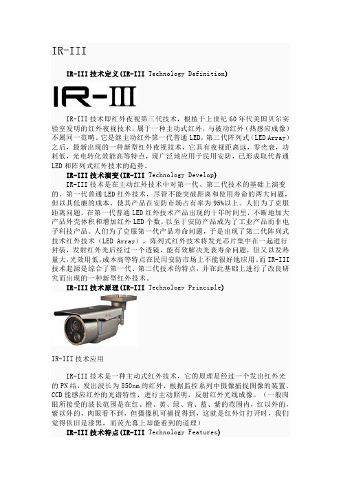
IR-IIIIR-III技术定义(IR-III Technology Definition)IR-III技术即红外夜视第三代技术,根植于上世纪60年代美国贝尔实验室发明的红外夜视技术,属于一种主动式红外,与被动红外(热感应成像)不属同一范畴。
它是继主动红外第一代普通LED,第二代阵列式(LED Array)之后,最新出现的一种新型红外夜视技术,它具有夜视距离远,零光衰,功耗低,光电转化效能高等特点,现广泛地应用于民用安防,已形成取代普通LED和阵列式红外技术的趋势。
IR-III技术演变(IR-III Technology Develop)IR-III技术是在主动红外技术中对第一代、第二代技术的基础上演变的。
第一代普通LED红外技术,尽管不能突破距离和使用寿命的两大问题,但以其低廉的成本,使其产品在安防市场占有率为95%以上。
人们为了克服距离问题,在第一代普通LED红外技术产品出现的十年时间里,不断地加大产品外壳体积和增加红外LED个数,以至于安防产品成为了工业产品而非电子科技产品。
人们为了克服第一代产品寿命问题,于是出现了第二代阵列式技术红外技术(LED Array),阵列式红外技术将发光芯片集中在一起进行封装,发射红外光后经过一个透镜,能有效解决光衰寿命问题,但又以发热量大,光效用低,成本高等特点在民用安防市场上不能很好地应用。
而IR-III 技术起源是综合了第一代、第二代技术的特点,并在此基础上进行了改良研究而出现的一种新型红外技术。
IR-III技术原理(IR-III Technology Principle)IR-III技术应用IR-III技术是一种主动式红外技术,它的原理是经过一个发出红外光的PN结,发出波长为850nm的红外,根据监控系列中摄像捕捉图像的装置,CCD能感应红外的光谱特性,进行主动照明,反射红外光线成像。
(一般肉眼所接受的波长范围是在红、橙、黄、绿、青、蓝、紫的范围内,红以外的,紫以外的,肉眼看不到,但摄像机可捕捉得到,这就是红外灯打开时,我们觉得依旧是漆黑,而荧光幕上却能看到的道理)IR-III技术特点(IR-III Technology Features)IR-III技术将第一、二代IR技术融合在一起,它仅由一个发光二极管组成,其发热量极小,其芯片部位仅为摄氏50度,曾一度被称为“冷光源”。
红外成像仪的基本原理及在地铁供电设备中的运用

红外成像仪的基本原理及在地铁供电设备中的运用一、红外成像仪的基本原理通过诸多科学家很多年的研究表明,红外线辐射是自然界存在的一种最为广泛的电磁波辐射,任何温度高于绝对零度(-273.16℃)就会不停地辐射出红外线,辐射出的红外线带有物体的温度特征信息,这就是红外技术探测物体温度高低和温度场分布的理论依据和客观基础。
红外线在大气中存在三个波长,分别在(1-2.5μm),(3-50 μm),(8-14μm)区域穿透比较好,衰减比较弱,一般红外线成像仪使用的波段为:短波(3-5μm);长波(8-14μm)。
红外成像仪可将不可见的红外辐射转换成可见的图像。
物体的红外辐射经过镜头聚焦到探测器上,探测器将产生电信号,电信号经过放大并数字化到成像仪的电子处理部分,再转换成我们能在显示器上看到的红外图像及温度。
红外成像检测基本原理是物体自身的红外辐射是各个方向的,辐射量取决于物体自身的温度以及它的表面辐射率,所有物体都有温度以及表面辐射率,所以所有物体都有红外辐射,物体温度越高,红外辐射越多,反之,物体温度越低,辐射越低;辐射率也一样,即使物体温度一样,高辐射率物体的辐射要比低辐射率物体的辐射要多。
所以物体的温度及表面辐射率决定着物体的辐射能力。
不同的材料、不同的温度、不同的表面光度、不同的颜色等,所发出的红外辐射强度都不同(辐射率不同)。
在检测过程中,由于辐射率对测温影响很大,因此必须选择正确的辐射系数,电力设备辐射率(ε)一般在0.85-0.95之间。
二、红外成像仪在地铁供电设备中的运用红外成像仪可以“面”的形式对目标整体实时成像,使操作者通过屏幕显示的图像热点追踪显示功能就能初步判断发热情况和故障部位,然后加以后续分析,从而高效率、高准确率地确认问题所在。
几乎所有利用或者发射能量的物体在发生故障前都会产生发热现象。
在一个电气接点发生故障之前及时发现并进行维修,可以节省或避免因此造成的生产停工、能源损耗、火灾甚至灾难性故障所带来的高昂代价,因此对地铁供电设备红外成像巡检是很有必要的,下面举一些地铁供电系统变电所典型设备案例进行描述。
休斯公司研制第三代红外凝视传感器

休斯公司研制第三代红外凝视传感器
佚名
【期刊名称】《船舶物资与市场》
【年(卷),期】1998(000)002
【摘要】美国海军陆战队最新式飞机——倾斜水平旋翼“海鹰”(Osprey)飞机将装备第三代前视红外(FLIR)夜视系统。
新一代 FLIR 系统为海军提供了导航能力,它不仅能够穿透云雾进行探测,还能够在恶劣的气候条件下工作。
与美军目前广泛使用的第二代 FLIR 系统相比,该系统的分辨率和探测距离都高于目前美军所使用的夜视系统,其目标瞄准和武器投射的远程距离都提高
【总页数】1页(P18-18)
【正文语种】中文
【中图分类】F416.6
【相关文献】
1.红外低轨星座凝视传感器的空间覆盖性能分析 [J], 邓勇;王春明;张中兆
2.低轨星座红外凝视传感器覆盖性能分析 [J], 王博;许丹;陈延军;安玮
3.休斯公司研制第三代红外凝视传感器 [J], 朱耘
4.欧洲第三代气象卫星选用法国Sofradir公司产红外传感器 [J], 高国龙
5.红外凝视传感器定量仿真及模型验证 [J], 张福娣;张建奇;徐茵
因版权原因,仅展示原文概要,查看原文内容请购买。
红外成像仪原理
红外成像仪原理红外成像仪是一种利用红外辐射进行成像的设备,它能够在夜间或低光条件下进行观测和监测,具有广泛的应用领域,包括军事、安防、消防、医疗、工业等。
其工作原理主要基于物体的红外辐射特性和红外探测技术。
首先,红外成像仪通过透镜系统收集被测物体发出的红外辐射,然后将红外辐射转换成电信号。
这些电信号经过信号处理电路进行放大、滤波和增强处理,然后传输给图像处理系统。
其次,图像处理系统将接收到的电信号转换成灰度图像,然后通过数字信号处理技术进行图像增强、增加对比度、去噪等处理,最终形成清晰的红外图像。
红外成像仪的工作原理主要依赖于物体的红外辐射特性。
所有物体都会发出红外辐射,其强度和波长分布取决于物体的温度和表面特性。
红外成像仪利用红外辐射特性可以实现对不同温度物体的探测和成像,因此在夜间或低光条件下也能够进行观测和监测。
红外探测技术是红外成像仪实现成像的关键。
目前主要有热释电探测器、焦平面阵列探测器和光学测温探测器等技术。
其中,热释电探测器是最常用的一种,它利用物体吸收红外辐射产生的热量来产生电信号,实现红外图像的获取。
红外成像仪在军事领域具有重要的应用价值,可以实现夜视观测、目标识别和导航定位等功能。
在安防领域,红外成像仪可以实现对夜间监控和防范,提高安全防护能力。
在医疗领域,红外成像仪可以用于热成像诊断,帮助医生进行疾病诊断和治疗。
总之,红外成像仪通过利用物体的红外辐射特性和红外探测技术,实现了对夜间或低光条件下的观测和监测。
其工作原理简单清晰,应用领域广泛,具有重要的应用价值和发展前景。
随着科技的不断进步,红外成像仪的性能和功能将会不断提升,为各个领域的应用带来更多的便利和可能性。
物联网技术与应用考试题库

物联网测试题目一、单选题(80)1、通过无线网络与互联网的融合,将物体的信息实时准确地传递给用户,指的是()。
CA、可靠传递B、全面感知C、智能处理D、互联网2、利用RFID 、传感器、二维码等随时随地获取物体的信息,指的是()。
BA、可靠传递B、全面感知C、智能处理D、互联网3、()给出的物联网概念最权威。
DA、微软B、IBMC、三星D、国际电信联盟4、(d)年中国把物联网发展写入了政府工作报告。
DA、2000B、2008C、2009D、20105、第三次信息技术革命指的是()。
BA、互联网B、物联网C、智慧地球D、感知中国6、IBM提出的物联网构架结构类型是().CA、三层B、四层C、八横四纵D、五层7、欧盟在()年制订了物联网欧洲行动计划,被视为“重振欧洲的重要组成部分”。
BA、2008B、2009C、2010D、20048、物联网的概念,最早是由美国的麻省理工学院在()年提出来的。
AA、1998B、1999C、2000D、20029、计算模式每隔()年发生一次变革。
CA、10B、12C、15D、2010、权威的物联网的概念是()年发布的《物联网报告》中所提出的定义。
DA、1998B、1999C、2000D、200511、2009年10月()提出了“智慧地球”。
AA、IBMB、微软C、三星D、国际电信联盟12、智慧地球是()提出来的. DA、德国B、日本C、法国D、美国13、三层结构类型的物联网不包括()。
DA、感知层B、网络层C、应用层D、会话层14、物联网的概念最早是()年提出来的。
BA、1998B、1999C、2000D、201015、我国开始传感网的研究是在()年。
AA、1999年B、2000年C、2004年D、2005年16、()年,正式提出了物联网的概念,并被认为是第三次信息技术革命。
BA、1998B、1999C、2000D、200217、物联网的概念最早是()提出来的。
智能网联1+X题库章节10(带答案)

1/42、在进行ACC功能测试时,目标车辆的宽度应在()m至()m之间。
A、 1.0 2.0B、 1.3 2.0C、 1.4 1.8D、 1.4 2.0正确答案:D2/42、在进行ACC功能测试时,环境温度可以在()℃至()℃范围内。
A、 -10 40B、 0 40C、 -10 30D、 0 30正确答案:B3/42、由于激光具有能量密度高、方向性好的特点,激光雷达的探测距离往往能达到()以上。
A、 100mB、 200mC、 300mD、 400m正确答案:A4/42、汽车上采用数据总线的原因是()。
A、提高技术含量B、降低生产成本C、降低维修难度D、便于用户使用正确答案:B5/42、舒适CAN总线系统数据传输速度是()。
A、 20Mbit/sB、 100kbit/sC、 500kbit/sD、 10Mbit/s正确答案:B6/42、用来控制智能雨刮、自动空调等系统的是()。
A、 A类网络B、 B类网络C、 D类网络D、 E类网络正确答案:A7/42、检测信号线电压、CAN线波形用到的仪器是()?A、万用表B、示波器C、诊断仪电脑D、网线检测仪正确答案:B8/42、车道保持辅助系统的开启速度是多少?()A、 55km/hB、 60km/hC、 65km/hD、 70km/h正确答案:C9/42、激光雷达传感器的供电线电压应为多少伏?()A、 0B、 5C、 12D、 24正确答案:C10/42、在测量视觉传感器搭铁线电阻时,点火开关应该置于什么位置?()A、 P档B、 S触点C、 ACCD、 ON正确答案:A11/42、在测量左前座椅通风风扇信号线波形时,应将示波器的()放在()上,()放在()上。
a.红表笔 b.黑表笔c.供电线 d.信号线e.搭铁线或蓄电池负极A、 acbeB、 adbeC、 aebeD、 adbd正确答案:B12/42、如果示波器中测量的CAN线波形太疏,无法显示一个周期,这时需要调节示波器的()A、振幅B、频率C、时间D、象限正确答案:C13/42、在进行视觉传感器标定时,将测试版放置在摄像头视野范围内,现需要将Y条变绿,需要()A、测试版左右移动B、测试版上下移动C、测试版前后移动D、测试版倾斜转动正确答案:B14/42、在进行激光雷达测试时,打开rviz的命令是?()A、 roslaunch velodyne_pointcloud VLP16_unch。
- 1、下载文档前请自行甄别文档内容的完整性,平台不提供额外的编辑、内容补充、找答案等附加服务。
- 2、"仅部分预览"的文档,不可在线预览部分如存在完整性等问题,可反馈申请退款(可完整预览的文档不适用该条件!)。
- 3、如文档侵犯您的权益,请联系客服反馈,我们会尽快为您处理(人工客服工作时间:9:00-18:30)。
这 种 成 像 偏 振 仪 的优 点是 , 由于 采 用 了微
测辐射 热计 探测 器 ,其成本 比基 于碲 镉汞 的传
感器低 了很 多,重量减 轻 了,功耗 也减少 了。还
IF A E M N H Y / O .1 NO6 U 0 0 N R R D( O T L )V L , .,J N2 1 3
一
,
,
’ ,。 ,
一
…
}
●
图 1 双 相 机 微 测辐 射 热计 斯 托克 斯 偏 振 仪 的示 意 图
异质 结场 效应 管 电光 逻 辑 电路 的单片 红 外像 红外技 术 通常 需要低 温致 冷 的工作条件 , 并采 用独 立 的读 出集 成 电路 。相 比之 下, O I DS
口 高 国 龙
和 () b 分别为该成像偏振仪 的内部 系统和 外形。
I .… 一 … 一
l 一 :毫下 - 1 {④^ 、 ● . / ’ j/ 0. /
r ‘、 , 。
o4 。
▲
-
L … .
P
;
-¨ ¨
美 国 O I 公 司 将 开 发 单 片 红 外 DS 成 像 与 读 出 电 路
元 结构。
公司 已经提高 了这种技 术, 他们 能够提供 一种将
红外 成像 与 晶体 管读 出 电路结合 在 一起 的集成
方ห้องสมุดไป่ตู้法。
该公 司 的首席科 学家 G o T y r 士介绍 ef al 博 o 说,通过在 同一个 外延 结构上 融合这些技术, 他 们 的 电光系 统将 可 以在 非致 冷的环 境 下进行 高 灵敏 度 的红 外成像 和 片外 通信 ,同 时它 的运 行 速度 也将得到 显著提 高。 O I D S公 司 的负 责人表 示,这 项技 术不 仅 有 潜力为 美 国空军 与 空间 导弹 防御 司令 部 节省 生产 成本 , 而且 还有 望在现有 的 以及 将来 的卫星 任 务 中获得 更 高 的可 靠 性和 更 高 的分 辨 率。另 外,该技 术将 可 以降低 一 些 民用 产 品的成本 并 提 高它们 的性能, 而使 民用产 品 的市场 更加充 从
振 仪 的外 形
光 电技 术, 们才实现 了包含 有源 / 他 无源光 学元
件 和 高性 能模拟 /数字元件 的集成 电路 的单片 制备 , 这也就让 许多光 学器件 、密集分布 高速模
拟元件 和低 功耗 高速 数 字元件在 单片 集 成 电路 上 的安装 工作显得 更加经 济。
口 岳 桢 干
h p / un1i . . /w t : j as p c nh t / or . a c t
清活 力 这 项 技 术 的核 心 部 分 是 基 于 一 种 新 颖 的 Ⅱ I
—
v族 材 料 结 构 的 半 导体 制 备 工 艺 ,这 是 一 种 已
取得 专利权 的平板光 电技 术 (O T 。通过平板 P E)
() b 图2 ( a )成像偏 振仪 的内部 系统, ()成像偏 b
消光比为 1 0,透 射 消 光 比 可 大 于 3 O。 图 1为该 成 像 偏 振 仪 的 系 统 示 意 图。图 2a ()
有,由于它无需使用低 温制冷部件 ,因而可 以在 那 些要 求成 像器 几 乎瞬 间启 动 的应用 场 合使用 ( 见 P o. f PE V 17 1,498 。 参 rc o S I , o. 49 7 10)
据 ww smi n u tr o a . r 网站报 w. c d co. d ycn e o t o 道, 作为军事和工业上运用 的通信 收发器、 电集 光 成平 台以及 红外传 感器类产 品的设 计厂家, 国 美 O I 司最近 从美 国空军研 究实 验 室 ( F L D S公 AR) 得到 一笔 70 0 美元 的资金, 5, 0 0 以开发基于 晶闸管
