上网伴侣:产品使用手册V1.2
宽带上网助手安装及使用手册
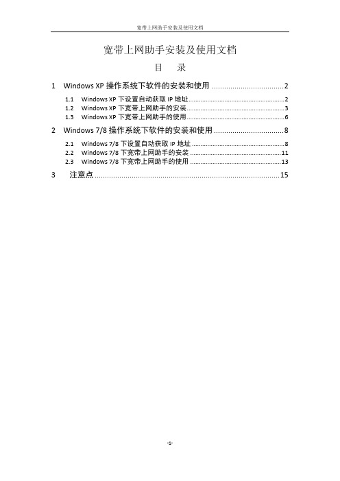
宽带上网助手安装及使用文档目录1Windows XP操作系统下软件的安装和使用 (2)1.1Windows XP下设置自动获取IP地址 (2)1.2Windows XP下宽带上网助手的安装 (3)1.3Windows XP下宽带上网助手的使用 (6)2Windows 7/8操作系统下软件的安装和使用 (8)2.1Windows 7/8下设置自动获取IP地址 (8)2.2Windows 7/8下宽带上网助手的安装 (11)2.3Windows 7/8下宽带上网助手的使用 (13)3注意点 (15)1Windows XP操作系统下软件的安装和使用安装及使用宽带上网助手前,将电脑设置为自动获取IP地址。
1.1Windows XP下设置自动获取IP地址(1).用鼠标右击电脑桌面上图标:选择属性,打开网络连接窗口。
(2).找到“网络连接”中的图标:一般电脑只会有一个本地连接,右键“本地连接”,选择“属性”。
(3).在弹出的“本地连接属性”窗口中,双击“Internet协议(TCP/IP)”(也可选中后点属性)。
(4).在“Internet 协议(TCP/IP)属性”对话框中,选择“自动获得IP地址(0)”和“自动获得DNS服务器地址(B)”两项,然后单击确定。
自动获取IP地址已配置完成。
自动获取IP地址后可以访问校园内网资源,如需要访问互联网请下载宽带上网助手后根据下列步骤安装、使用。
Windows XP下宽带上网助手的安装(1).解压下载的双击安装程序根据安装向导所示,单击“下一步(N)”;(2).选择要安装到的文件夹下,然后单击“下一步(N)”;(4).建议选择创建桌面快捷图标,单击“下一步(N)”;安装完毕后,单击完成。
1.2Windows XP下宽带上网助手的使用(1).双击桌面上快捷图标:打开上网助手,出现如下图所示:(2).输入正确的用户名及密码后,单击“连接”,在验证过程中:连接成功:同时电脑任务栏上会显示:到此已经连接成功。
上网伴侣:产品使用手册

东起骆下公路,西至富春江路,北至迎宾路,南至29国道
慈溪
东起东三环北路,西至西外环路,北至中横线,南至29国道
奉化
东至甬临线,西至西环路,北至大成东路,南至岳林东路
宁海
东起滨海中路,西至山河路,北起时代大道,南至纺织东路
象山
东起巨鹰路,西至城西路,北至靖南大街,南至滨海大道
余姚
东起城东路,西至西环路,北起丰山路,南至西环南路
仙居
仙居县城北至大庙前村,南至台金高速,东至永安公园,西至台金高速入口区域;仙居郊区,35省道城区至横溪镇主干道,以及各乡镇政府所在地连续覆盖
(7)【嘉兴地区3G网络整体覆盖图】
县区
覆盖区域
嘉禾
北起320国道,东至双溪路,南至二环南路,西至320国道区域内,周边新塍镇、城西工业园区、余新镇、城东大桥村的中心区域
浦江
东以永在大道为界;西毛亚线为界;北以月泉西路、月泉东路为界;南以以S047省道为界。
东阳
西以城南西路为界,东以迎宾大道为界,北以横店镇、南马镇为界,南以甬金高速公路为界,,横店镇,南马镇以覆盖本乡镇为主
永康
西以西塔路、环城西路为界,东以花园大道为界,北以城北路、330国道为界,南以城南路为界。
武义
建德
建德连续覆盖区域为建德主城区。东至环城北路与江滨路交叉口,以严州大道为界西北,以新安东路为界东南
淳安
主城区基本实现连续覆盖。东起S302与S302交叉口,西至新安北路;北起浪排线,南至南山大街。
(3)【宁波地区3G网络整体覆盖图】
县区
覆盖区域
主城区
宁波主城区东至学院路,西至盛莫路,北至江北连接线和北环西路,南起环城南路,上述封闭区域TD室外信号基本保证
WIFI伴侣路由器说明书CMCC

WIFI伴侣说明书目录目录 (2)物品清单 (4)第一章用户手册简介 (5)1.1用途 (5)1.2用户手册概述 (5)第二章产品概述 (6)2.1产品简介 (6)2.2产品特性和规格说明 (6)2.2.1产品特性 (6)2.2.2产品规格 (7)第三章硬件安装 (8)3.1面板布置 (8)3.1.1前面板 (8)3.1.2后面板 (8)3.2系统需求 (9)3.3安装环境 (9)3.4硬件安装步骤 (9)3.4.1有线网络安装 (9)第四章配置指南 (10)4.1登录便WIFI伴侣 (10)4.2无线扩展向导 (13)4.3无线设置 (14)4.3.1基础设置 (14)4.3.2高级设置 (15)4.3.3安全设置 (16)4.3.4无线访问策略 (16)4.3.5 WDS设置 (17)4.3.6 WPS设置 (18)4.3.7站点列表 (19)4.4 WAN设置 (19)4.4.1 WAN设置 (19)4.4.2 WAN高级 (20)4.5 LAN 设置 (21)4.5.1 LAN 设置 (21)4.5.2 静态DHCP 设置 (22)4.5.3 DHCP客户表 (22)4.6QOS设置 (23)4.6.1QOS设置 (23)4.7网络安全 (24)4.7.1端口过滤 (24)4.7.2 MAC过滤 (24)4.7.3 IP过滤 (25)4.7.4 URL过滤 (25)4.7.5防火墙 (26)4.8服务设置 (27)4.8.1 DMZ设置 (27)4.8.2虚拟主机 (27)4.8.3 DDNS (28)4.8.4 NTP设置 (28)4.9系统管理 (29)4.9.1工作模式 (29)4.9.2配置文件 (29)4.9.3 固件升级 (30)4.9.4 密码管理 (30)4.9.5 重启系统 (30)4.9.6 系统日志 (31)4.10系统状态 (32)4.10.1当前状态 (32)4.10.2数据统计 (32)无线概要 (33)无线模式 (33)常见问题 (34)物品清单小心打开包装盒,检查包装盒里应有以下配件:一台无线路由器一本用户手册一张保修卡一张合格证注意:如果发现产品有所损坏或者任何配件短缺的情况,请及时和当地经销商联系。
上网伴侣业务培训材料

反馈收集
通过各种渠道收集客户的反馈和建议。
反馈分析
对反馈进行分析和整理,找出问题所在和 改进方向。
改进措施
反馈回复
制定改进措施,优化服务流程和提升服务 质量。
向客户提供反馈回复,告知改进措施和结 果,提升客户满意度。
06
上网伴侣业务未来发展 展望
技术创新与升级
5G/6G网络技术应用
随着5G/6G网络的普及,上网伴侣业务将进一步优化网络连接速度和稳定性,提 供更高效、更流畅的网络服务。
跨界合作
与其他产业领域进行合作,如电商、 金融、游戏等,实现资源共享和互利 共赢。
国际市场拓展
积极开拓国际市场,提升品牌知名度 和影响力,吸引更多国际用户。
谢谢观看
家庭用户
需要为家庭成员提供共享 网络和丰富的内容服务。
业务优势
覆盖广泛
上网伴侣业务覆盖全国范 围,无论城市还是乡村, 都能享受到高速稳定的网 络服务。
价格实惠
相对于其他网络服务提供 商,上网伴侣业务的价格 更加实惠,性价比较高。
服务优质
提供24小时全天候客服服 务,解决用户在使用过程 中遇到的问题,提升用户 满意度。
上网伴侣业务培训材料
目录
• 上网伴侣业务简介 • 上网伴侣业务使用流程 • 上网伴侣业务常见问题解答 • 上网伴侣业务推广策略 • 上网伴侣业务客户服务 • 上网伴侣业务未来发展展望
01
上网伴侣业务简介
产品特点
高速稳定的网络连接
个性化定制服务
上网伴侣业务提供高速、稳定的网络 连接,满足用户在线浏览、下载、游 戏等需求。
AI与大数据技术融合
利用人工智能和大数据技术,实现个性化推荐、智能客服、精准营销等功能,提 升用户体验和业务效率。
上网伴侣产品使用手册终审稿)

东起骆下公路,西至富春江路,北至迎宾路,南至29国道
慈溪
东起东三环北路,西至西外环路,北至中横线,南至29国道
奉化
东至甬临线,西至西环路,北至大成东路,南至岳林东路
宁海
东起滨海中路,西至山河路,北起时代大道,南至纺织东路
象山
东起巨鹰路,西至城西路,北至靖南大街,南至滨海大道
余姚
东起城东路,西至西环路,北起丰山路,南至西环南路
安吉
北起上马岭,南至阴山脚,东起营盘山,西至东湾。
长兴
北起齐山路,南至潘家浜,东起经四路,西至梅花庄。
德清
北起三桥,南至俞家坑,东起双山路,西至职业高中
南浔
北起申苏浙皖高速,南至曹家湾,东起虹阳路,西至南浔大道。
(10)【衢州地区3G网络整体覆盖图】
县区
覆盖区域
主城区
东以上大线、东港三路为界;西以大桥支路、花大线、白云山路为界;北以杭金衢、清泰外国语学校;南以廿里、大洲为界。
建德
建德连续覆盖区域为建德主城区。东至环城北路与江滨路交叉口,以严州大道为界西北,以新安东路为界东南
淳安
主城区基本实现连续覆盖。东起S302与S302交叉口,西至新安北路;北起浪排线,南至南山大街。
(3)【宁波地区3G网络整体覆盖图】
县区
覆盖区域
主城区
宁波主城区东至学院路,西至盛莫路,北至江北连接线和北环西路,南起环城南路,上述封闭区域TD室外信号基本保证
刷微博:一般10-100K/个微博
挂股票:约10-50M/小时
在线视频:一般100-500M/部
8、套餐流量万一用完了怎么办会不会产生高额费用
9、
“上网伴侣”套餐外资费为0.05元/M,流量不足200M、50M和0M的时候都会通过短信进行提醒,同时,还提供按周使用提醒服务。
爱国者移动伴侣快速使用指南.CHS.V1.2

7 / 18
aigo 爱国者移动伴侣
B.白色闪烁:已连接 USB2.0 且正在读写。 C.蓝色常亮:已连接 USB3.0。 D.蓝色闪烁:已连接 USB3.0 且正在读写。 无线(WLAN)指示灯: 1. 蓝灯闪烁表示系统启动状态,系统启动完成 后,灯停止闪烁。 2. 蓝色常亮:WiFi 有信号。 3. LED 灯熄灭有下列情况: A. 设备开机,但已经关闭无线信号 B. 设备关机。 C. 设备在移动硬盘模式。 互联网(WAN)指示灯: 1. 无线连接(通过其他无线路由器的 WiFi 信号 连接到互联网): A. 绿色常亮:无线信号很好。 B. 绿色慢速闪烁:无线信号弱。
8 / 18
aigo 爱国者移动伴侣
C. 不亮:没有连接互联网。 2. 有线连接(通过 RJ45 接口有线接入互联网):
A. 蓝色常亮:互联网连接成功。 B.不亮:没有连接互联网。
多功能线使用方法
9 / 18
aigo 爱国者移动伴侣
1.3 产品参数及配置
A. 本机充电规格:5V,1A≦电流≦2.1A,充 电接口为 USB2.0 Micro B。关机状态下, 无线硬盘型使用 IPAD 充电器约 3 小时充 满,使用普通充电器约 5-6 小时充满。无线 固态硬盘型时间减少约 1 小时
aigo WiFi Disk 预置在本机存储空间中,请自行安装;也可到 苹果 APP Store、各大安卓应用市场自行下载。
第三方客 户端
Power7 Mobile Fun
Wifi-Disk
第三方
Oplayer、
SAMBA 播 Goodplayer
移动伴侣客户端软件使用说明V3.0

爱国者移动伴侣 客户端软件使用说明V3.0目录免责声明 (3)特别提示: (4)一、设备的准备与连接 (4)1.1开机 (4)1.2 WiFi信号的连接 (4)1.2.1 Windows 平台 (4)1.2.2 iOS 平台 (5)1.2.3 Android 平台 (9)1.3 移动网络存储服务器(移动NAS)模式 (14)二、客户端软件的安装 (14)2.1 Windows 平台 (15)2.2 iOS 平台 (16)2.3 Android 平台 (16)三、Windows客户端软件的界面说明 (19)四、iOS、Android客户端软件的界面说明 (21)4.1登录设备 (21)4.2 DLNA目录 (25)4.3 文件播放 (28)4.3.1 视频播放 (28)4.3.2 音乐播放 (30)4.3.3 图片浏览 (30)4.3.4文档浏览 (31)4.3.5 DLNA推送 (32)4.3.6 AirPlay功能 (34)4.4 文件管理 (36)4.4.1 分享按钮 (38)4.4.2 操作按钮 (38)4.4.3 传输按钮 (43)4.5设置界面 (45)4.5.1 设备设置 (47)4.5.1.1 无线设置 (47)4.5.1.2 局域网设置 (51)4.5.1.3 互联网设置 (53)4.5.1.4 系统设置 (57)4.5.2 来宾用户 (60)4.5.3 缓存设置 (61)4.5.4 语言设置 (62)4.5.5 关于 (62)4.5.6 注销 (63)五、使用第三方软件进行访问 (63)免责声明由于产品的更新,本手册中的图片和文字可能与您的设备中显示的图文略有不同,某些细微的变更将不会影响您的操作,请以实物操作为主。
一、感谢您购买爱国者移动伴侣产品。
在使用本产品之前,请认真阅读快速使用说明和本说明书。
当您开始使用爱国者移动伴侣产品时,爱国者电子认为您已经认真阅读了本说明书。
二、本产品为移动存储产品,用于用户数据的冗余备份,请用户在使用过程中及时对其中的数据进行备份。
LBT1 LoRaWAN Bluetooth Tracker 用户手册说明书
LBT1 LoRaWAN Bluetooth Tracker User Manual Document Version: 1.2.0Image Version: v1.2.01.Introduction (4)1.1What is LBT1 LoRaWAN Bluetooth Tracker (4)1.2Specifications (5)1.3Features (5)1.4Applications (6)1.5Hardware Change log (6)2.How to use LBT1? (7)2.1Activate LBT1 (7)2.2How it works? (7)2.3Quick guide to connect to LoRaWAN server (OTAA) (9)2.4Uplink Payload (12)2.4.1Payload Analyze (12)2.4.2Add Payload format in TTN (16)2.5Downlink Payload (17)2.5.1General Downlink commands: (17)2.5.2Commands special design for LBT1 (17)Set Payload Mode: (17)Set BLEMASK: (17)Set AT+SLEEP: (18)Disable/Enable Vibration: (18)Show All scanned UUID in console: (18)2.6LED Status (19)2.7Button Function (19)2.8USB Port Function (19)2.9Firmware Change Log (19)3.Case Study (20)3.1User Mapwize service for indoor positioning. (20)e AT Command (21)4.1Access AT Command (21)4.2Common AT Command Sequence (23)4.2.1Multi-channel ABP mode (Use with SX1301/LG308) (23)5.Upload Firmware (24)6.FAQ (25)6.1What is the frequency range of LT LoRa part? (25)6.2How to change the LoRa Frequency Bands/Region? (25)6.3What is the pin mapping for the USB program cable? (25)7.Trouble Shooting (25)7.1Why I can’t join TTN in US915 /AU915 bands? (25)7.2I see AT_ERROR when I type commands? (25)7.3Why I am getting Empty payload? (26)8.Order Info (26)9.Packing Info (26)10.Support (27)11.Reference (27)1.Introduction1.1What is LBT1 LoRaWAN Bluetooth TrackerLBT1 is a Long Range / low power consumption LoRaWAN Bluetooth tracker. LBT1 scans and find the nearest i-Beacon info and send to IoT server via LoRaWAN wireless network. IoT Server should have a pre-configure position mapping for beacons in order to trace the location of LBT1 tracker.LBT1 targets for indoor positioning for people and things.LBT1 has motion detect feature, it will also detect walk steps and uplink the value.LBT1 is powered by 1000mA rechargeable Li-on battery and charge circuit, which target for real time tracking with short tracking uplink interval.1.2SpecificationsMicro Controller:➢MCU: STM32L072CZT6➢Flash:192KB➢RAM:20KB➢EEPROM: 6KB➢Clock Speed: 32MhzCommon DC Characteristics:➢Supply Voltage: 5V via USB port or Internal 1000mAh battery➢Operating Temperature: -40 ~ 85°CLoRa Spec:➢Frequency Range,✓Band 1 (HF): 862 ~ 1020 Mhz➢168 dB maximum link budget.➢High sensitivity: down to -148 dBm.➢Bullet-proof front end: IIP3 = -12.5 dBm.➢Excellent blocking immunity.➢Built-in bit synchronizer for clock recovery.➢Preamble detection.➢127 dB Dynamic Range RSSI.➢Automatic RF Sense and CAD with ultra-fast AFC.➢LoRaWAN 1.0.3 SpecificationBattery:➢1000mA Li-on Battery powerPower Consumption➢Sleeping Mode: 25uA➢BLE Scanning Mode: 30mA➢LoRa Transmit Mode: 125mA @ 20dBm 44mA @ 14dBm 1.3Features✓LoRaWAN 1.0.3 Class A✓STM32L072CZT6 MCU✓Frequency bands KR920/US915/IN865/EU868/AS923/AU915✓Bluetooth iBeacon scanning✓Walking steps counter✓Power Monitoring✓Charging circuit via USB port✓Tri-color LED, Alarm button1.4Applications✓Logistics and Supply Chain Management✓Things / Asserts management.✓Human tracking1.5Hardware Change logLBT1 v1.0:Release.2.How to use LBT1?2.1Activate LBT1The LBT1 has three working modes:✓Deep Sleep Mode-1: LBT1 doesn’t have any LoRaWAN activate. This mode is used for shipping to save battery life and avoid faulty press during shipping. User need to use needle to press the side button to activate device.✓Deep Sleep Mode-0: LBT1 doesn’t have any LoRaWAN activate. This mode is used for storage to save battery life. User can double click Alarm button or use needle to press the side button to activate device.✓Keep Alive Mode: In this mode, LBT1 works as LoRaWAN Sensor to Join LoRaWAN network and send out iBeacon’s UUID & ADDR to LoRaWAN server, default interval is 7 minutes.Between each scanning/tx/rx periodically, LBT1 will be in STOP status (IDLE status), in STOP mode, device has the same power consumption as Deep Sleep mode.✓Walking Mode: In this mode, LBT1 sends the iBeacon’s UUID & ADDR to LoRaWAN server ina much shorter interval (10 seconds exclude scanning time).The LBT1 is set in Deep Sleep Mode-1 by default; the alarm button and reset button is used toNote: After device is activate, there are two ways to deactivate:a)Use AT Command (Need USB to TTL Adapter)b)Or through downlink command (0x0901).2.2How it works?The LBT1 is working as LoRaWAN OTAA Class A end node. Each LBT1 is shipped with a worldwide unique set of OTAA and ABP keys. User needs to input the OTAA or ABP keys in the LoRaWANnetwork server so to register. LBT1 will join the LoRaWAN network and start to transmit data. Thedefault period for each uplink is 7 minutes (AT+TDC timer).2.3Quick guide to connect to LoRaWAN server (OTAA)Here is an example for how to join the TTN LoRaWAN Server. Below is the network structure, in this demo we use LG308 as LoRaWAN gateway.The LG308 is already set to connect to TTN . What the rest we need to is register the LBT1 to TTN:Step 1: Create a device in TTN with the OTAA keys from LBT1.Each LBT1 is shipped with a sticker with the default device EUI as below:Input these keys in their LoRaWAN Server portal. Below is TTN screen shot: Add APP EUI in the applicationAdd APP KEY and DEV EUIStep 2: Double click alarm button to activate the LBT1Step 3: LBT1 will auto join to TTN network via the LoRaWAN coverage by LG308. After join success, LBT1 will start to scan nearby valid iBeacon and upload message to IoT server.If LBT1 can’t find a valid iBeacon in three scanning ( 3 times x 5second/scan), it will fill the uuid and addr with all 0x00 and upload2.4Uplink Payload2.4.1Payload AnalyzeDifferent MODE has different payload:0FC70000000145454646304C000215:0112233445566778899AABBCCDD EEFF0:01000400C3:E9270F1C27DA454631324544333344323135414530394C000215:A8400227025030114240282006DEEF12:01000400C3:ED33D215AE090FBF 00000003414242434344444545464630303034443030314243332D303734 4C000215:0112233445566778899A ABBCCDDEEFF0:004D 001B C3:C406AB5DC9D8:-074✓BAT: Ex1: 0x4B45 & 0x3FFF ⇒ 3901 (mV).✓Alarm: it is the highest bit of the 3rd byte of the payload, when this bit is 0, it is a normal uplink message, if this bit is 1, it is a uplink message triggered by Alarm.✓Steps: The 0 ~ 6 bits of 3rd byte and 4th , 5th byte compose the steps. It increases when walk.Range is fromMin: 0b(000 0000 0000 0000 0000 000) = 0Max: 0b(111 1111 1111 1111 1111 1111) = 0x(7F FF FF ) = 8,388,607✓MODE: Define the payload format.✓UUID: The uuid from the strongest iBeacon.✓ADDR: The ADDR from the strongest iBeacon✓MAJOR: The MAJOR from the strongest iBeacon.✓MINOR: The MAJOR from the strongest iBeacon.✓Measured Power: The Measured Power from the strongest iBeacon.✓RSSI: The RSSI from the strongest iBeacon.2.4.2Add Payload format in TTNIn TTN, use can add a custom payload so it shows friendly.In the page Applications --> Payload Formats --> Custom --> decoder to add the decoder from: /downloads/index.php?dir=LoRa_End_Node/LBT1_LoRaWAN_BLE_Track er/Decoder/2.5Downlink PayloadLBT1 supports configuration via LoRaWAN downlink command. See this link to check how to use them in different platform:/index.php?title=Main_Page#Use_Note_for_ServerThere are two parts of commands for downlink:2.5.1General Downlink commands:These commands are to configure:✓General system settings like: uplink interval.✓LoRaWAN protocol & radio related command.These commands can be found on the downlink command wiki:/index.php?title=End_Device_Downlink_Command2.5.2Commands special design for LBT1These commands are to design for the working LBT1:Set Payload Mode:➢AT Command:AT+MOD=2 // Set Payload MOD =2AT+MOD=? // Get current work MOD➢Downlink Payload:0xA101 // Same as AT+MOD=10xA102 // Same as AT+MOD=2Set BLEMASK:BLEMASK is to filter the unwanted BLE iBeacons during scan. For example, if BLEMASK is 123456. LBT1 will only uplink uuid info which include 123456. It will ignore all other iBeacons which doesn’t contact 123456 in the uuid.Note: BLEMASK range is 6 ~ 10 bytes. If AT+BLEMASK < 6 bytes, BLEMASK will be disable.➢AT Command:AT+BLEMASK=123456 // Set BLEMASK = 123456AT+BLEMASK=0 // disable BLEMASK➢Downlink Payload: (Prefix : 0xA5)Example:// Set BLEMASK to 123456Set AT+SLEEP:Set device to Deep Sleep Mode, if device is in Deep Sleep Mode, user need to double click the Alarm button to active it.➢AT Command:0x0901: AT+SLEEP=1 → Set to Deep Sleep Mode 1.0x0900: AT+SLEEP=0 → Set to Deep Sleep Mode 0.➢Downlink Payload: (prefix: 0x09)0x0900 // Same as AT+SLEEP=10x0901 // Same as AT+SLEEP=0Disable/Enable Vibration:Enable / Disable Vibration. (Since firmware v1.2.0)➢AT Command:AT+VIB=1 → Enable Vibration.AT+VIB=0 → Disable Vibration.➢Downlink Payload: (prefix: 0x09)0xA600 // Same as AT+VIB=00xA601 // Same as AT+VIB=1Show All scanned UUID in console:Show all scanned UUID in serial console. This command will not work after reset the device, need to re-enter again.➢AT Command:AT+SHOWID → Enable UUID scanned log.2.6LED StatusSee work flow2.7Button FunctionRESET button:Press this button will reboot the device. Device will process OTAA Join to network again.RED alarm button:See work flow2.8USB Port FunctionThe USB interface of LBT1 has below functions:✓Power on the device✓Recharge the LBT1 battery✓Access UART console of LBT1✓Upgrade the firmware of LBT12.9Firmware Change LogSee this link.3.Case Study3.1User Mapwize service for indoor positioning. Network Structure:Please check this URL for instruction:/index.php?title=Mapwizee AT Command4.1Access AT CommandLBT1 supports AT Command. User can use a USB to TTL adapter to connect to LBT1 for using AT command, as below.In PC, User needs to set serial tool baud rate to 9600 to access serial console for LBT1. LBT1 will output system info once power on and user will be able to send AT commands:Below are the available commands, a more detail AT Command manual can be found at AT Command ManualAT+<CMD>? : Help on <CMD>AT+<CMD> : Run <CMD>AT+<CMD>=<value> : Set the valueAT+<CMD>=? : Get the valueGeneral CommandAT: AttentionAT?: Short HelpATZ: MCU ResetAT+TDC: Application Data Transmission IntervalKeys,IDs and EUIs managementAT+APPEUI: Application EUIAT+APPKEY: Application KeyAT+APPSKEY: Application Session KeyAT+DADDR: Device AddressAT+DEUI: Device EUIAT+NWKID: Network ID(You can enter this command change only after successful network connection)AT+NWKSKEY: Network Session KeyJoining and sending date on LoRa? networkAT+CFM: Confirm ModeAT+CFS: Confirm StatusAT+JOIN: Join LoRa? NetworkAT+NJM: LoRa? Network Join ModeAT+NJS: LoRa? Network Join StatusAT+RECV: Print Last Received Data in Raw FormatAT+RECVB: Print Last Received Data in Binary FormatAT+SEND: Send Text DataAT+SENB: Send Hexadecimal DataLoRa network managementAT+ADR: Adaptive RateAT+CLASS: LoRa Class(Currently only support class AAT+DCS: Duty Cycle SettingAT+DR: Data Rate (Can Only be Modified after ADR=0)AT+FCD: Frame Counter DownlinkAT+FCU: Frame Counter UplinkAT+JN1DL: Join Accept Delay1AT+JN2DL: Join Accept Delay2AT+PNM: Public Network ModeAT+RX1DL: Receive Delay1AT+RX2DL: Receive Delay2AT+RX2DR: Rx2 Window Data RateAT+RX2FQ: Rx2 Window FrequencyAT+TXP: Transmit PowerAT+SLEPP: device is in Deep Sleep ModeInformationAT+RSSI: RSSI of the Last Received PacketAT+SNR: SNR of the Last Received PacketAT+VER: Image Version and Frequency BandAT+FDR: Factory Data ResetAT+PORT: Application PortAT+CHS: Get or Set Frequency (Unit: Hz) for Single Channel ModeAT+CHE: Get or Set eight channels mode, Only for US915, AU915, CN4704.2Common AT Command Sequence4.2.1Multi-channel ABP mode (Use with SX1301/LG308)If device has not joined network via OTAA:AT+FDRAT+NJM=0ATZIf device already joined network:AT+NJM=0ATZ5.Upload FirmwareUser can upload firmware for bug fix or new feature added.Firmware Location:/downloads/index.php?dir=LoRa_End_Node/LBT1_LoRaWAN_BLE_Track er/Image/Upgrade Instruction:/index.php?title=Firmware_Upgrade_Instruction_for_STM32_base_prod ucts#Hardware_Upgrade_Method_Support_List6.FAQ6.1What is the frequency range of LT LoRa part?Different LBT1 version supports different frequency range, below is the table for the working6.2How to change the LoRa Frequency Bands/Region?User can follow the introduction for how to upgrade image. When download the images, choose the required image file for download.6.3What is the pin mapping for the USB program cable?Pin Color USB Pin UART pin ST-Link Pin1Red VCC N/A+5V2White D- (N/A)LGT-RXD SWDIO3Green D+(N/A)LGT-TXD SWCLK4ID (N/A)N/A5Black GND GND GND7.Trouble Shooting7.1Why I can’t join TTN in US915 /AU915 bands?It is about the channels mapping. Please see this link for detail.7.2I see AT_ERROR when I type commands?When you type command, it is possible that the ibeacon scanning conflict with serial input so you see AT_ERROR. Especially in walking mode where this is in a short scanning period.To overcome this issue, you can:1)Try to type the command in a txt file and paste it to the console to shorter the input time forcommand.2)Try to run AT+FDR first to reset the device to factory default and type.7.3Why I am getting Empty payload?The LBT1 payload if include motion sensor will have 52 bytes, according to the LoRaWAN protocol. The LoRaWAN server will discard this payload on DR0 in AU915/US915 bands. So each packet sent in DR0 will be seen as empty payload8.Order InfoPart Number: LBT1-XXXXXX: The default frequency band✓AS923: LoRaWAN AS923 band✓AU915: LoRaWAN AU915 band✓EU433: LoRaWAN EU433 band✓EU868: LoRaWAN EU868 band✓KR920: LoRaWAN KR920 band✓US915: LoRaWAN US915 band✓IN865: LoRaWAN IN865 band✓CN470: LoRaWAN CN470 band9.Packing InfoPackage Includes:✓LBT1 LoRaWAN Bluetooth Tracker x 1✓USB program cable x 1✓USB recharge cable x 1✓Sling x 1Dimension and weight:✓Device Size: 85 x 48 x 15 cm✓Device Weight: 50g✓Package Size: 10 x 8.5 x 4 cm✓Package Weight: 111g10.Support➢Support is provided Monday to Friday, from 09:00 to 18:00 GMT+8. Due to different timezones we cannot offer live support. However, your questions will be answered as soon as possible in the before-mentioned schedule.➢Provide as much information as possible regarding your enquiry (product models, accurately describe your problem and steps to replicate it etc) and send a mail to*******************11.Reference✧Product Page , DataSheet✧Image Download。
网Labels 网络设备用户指南说明书
Installation GuideIf the Power LED does not light, check that the power cable is plugged incorrectly and that the power source is good. If this action does not resolve theproblem, see “Troubleshooting” in the hardware installation guide.3. Connect devices to the switch.• Use Category 5e (Cat5e) for copper ports at 1000 Mbps.• Use NETGEAR AGM731F or AGM732F for fiber ports at 1000 Mbps.• Use Category 6A (Cat6a) for copper ports at 10 Gbps.• Use NETGEAR AXM761, AXM762, or AXM763 for fiber ports at 10 Gbps.Note:Fiber SFP modules are shipped separately. For more information aboutinstalling an SFP module, see the hardware installation guide on the resource CD.Perform the Initial ConfigurationYou can manage this switch through its web interface, or by using the command-lineinterface (CLI) through a console port. This guide describes the web method. TheCLI method is also described to determine a DHCP-assigned IP address or to useezconfig to assign a static IP address. For web management, follow one of thefollowing procedures, depending upon how your computer is set up:• Computer in DHCP client mode without DHCP server• Computer with static IP address• Computer in DHCP client mode with DHCP serverComputer in DHCP Client Mode Without DHCP ServerWARNING!! If no DHCP server is present, the switch assumes a default IPaddress of 169.254.100.100 and a subnet mask of 255.255.0.0. Theswitch must be in the same subnet as the computer when in DHCP-client mode without a DHCP server present. Use this IP value to login to the switch (see “Login to the Switch from the Web”).Computer with Static IP AddressWhen the computer is in this mode, the switch must be assigned a static IP address.To assign a static IP address, connect a VT100/ANSI terminal or a workstation toone of the switch’s console ports. A cable for the mini USB port is supplied.1. Start a terminal emulation program (TEP):• Windows XP or earlier. Use HyperTerminal.• Windows Vista or later. Use a TEP from the Internet.• Macintosh. Use ZTerm.• UNIX. Use a terminal emulator such as TIP.2. Select a console port using the console switch on the rear panel:• Mini USB port (cable included).Note:You might need to install the USB serial port driver available on theresource CD before you can use the USB port on the computer to connect tothe switch.• DB9 (cable not included).3. Configure the TEP to use the following settings (written below the connector onthe switch rear panel):• Baud rate. 115200 bps• Data bits. 8• Parity. none• Stop bits. 1• Flow control. none4. At the command prompt User:, log in to the switch using the user nameadmin and press Enter.5. At the password prompt, press Enter again (no password is needed for initialconfiguration).6. At the next command prompt, type ezconfig and press Enter.The ezconfig utility is now running in the switch.7. Use the ezconfig utility to set up your static IP address and subnet mask asshown in the example.Make sure that the switch IP address is in the same subnet as the computer.ProSafe M7100 Managed SwitchStart HereBefore you begin installation of your switch, check the package contents listed in the hardware installation guide on the resource CD that came with your switch. If any item is missing or damaged, contact your place of purchase.The resource CD for your switch also includes the software administration guide and a command-line interface reference manual.Follow these quick steps to install your switch.Set up the SwitchPrepare the site so that the mounting, access, power source, and environmental requirements are met. If you have any questions about these requirements, see the hardware installation guide for your switch on the resource CD.1. Install the switch using one of the following methods:• On a flat surface. Put one of the rubber footpads that came with the switch on each of the four concave spaces on the bottom of the switch.• In a rack. Use the rack-mount kit supplied with your switch, following the installation instructions included with the kit.2. Apply AC power.When you apply power, the Power LED blinks yellow as it conducts a power-on self-test (POST). After the switch passes the POST, the LED turns green. The switch is now functional.If the POST fails, the Power LED remains yellow (see “Troubleshooting” in the hardware installation guide for assistance).October 2012This symbol was placed in accordance with the European Union Directive 2002/96 on the Waste Electrical and Electronic Equipment (the WEEE Directive). If disposed of within the European Union, this product should be treated and recycled in accordance with the laws of your jurisdiction implementing the WEEE Directive.©2012 by NETGEAR, Inc. All rights reserved. NETGEAR and the NETGEAR logo are registered trademarks of NETGEAR, Inc. in the United States and/or other countries. Other brand and product names are trademarks orregistered trademarks of their respective holders. Information is subject to change without notice.For the complete EU Declaration of Conformity, visit/app/answers/detail/a_id/11621/.For indoor use only in all EU countries and Switzerland.8. Use this IP value to log in to the switch.See Login to the Switch from the Web .For information about how to perform extensive CLI management, see both the CLI reference manual for your switch and the software administration guide.(switch) #ezconfigEZ Configuration Utility--------------------------------Hello and Welcome!This utility will walk you thru assigning the IP address for the switch management CPU. It will allow you to save the changes at the end. After the session, simply use the newly assigned IP address to access the Web GUI using any public domain Web browser.Admin password is not defined.Do you want to assign the admin password (password length should vary in a range of 8 - 64 characters)? (Y/N/Q)The 'enable' password required for switch configuration via the command line interface is currently not configured.Do you want to assign it (password length should vary in a range of 8 - 64 characters) (Y/N Q)? nAssigning an IP address to your switch management Current IP Address Configuration --------------------------------IP Address Assignment Mode: None IP Address: 0.0.0.0Subnet mask: 0.0.0.0Default Router IP: 0.0.0.0IP address is not assigned. What do you want to do?C - Configure IP address manually.D - Assign IP address for the switch using DHCP mode(current IP address will be lost).N - Do nothing and go to the next question.Q - Quit. - Help.(C/D/N/Q/?)? cIP Address: 10.10.10.1Network mask: 255.255.255.0Default Router IP: 10.10.10.254Assigning System Name, System Location and System Contact to your switch management Current Configuration--------------------------------System Name:System Location:System Contact:Do you want to apply and save the changes (Y/N)? y Config file 'startup-config' created successfully .The configuration changes have been applied and saved.Please enter 'show running-config' to see the final configuration.Computer in DHCP Client Mode with DHCP ServerBy default, the switch is configured as a DHCP client to obtain its IP address from a DHCP server in the connected network. You need to access the switch from the serial console port.1.Make sure that the switch is connected to a DHCP server.2. Find the switch IP address that the DHCP server assigned.a. Perform steps 1 through 3 of the procedure Computer with Static IP Address .b. Type the show network command, and press Enter . A screen displaysthat shows the active switch IP address.c. Use this IP address to log in to the switch through its web management interface (see Login to the Switch from the Web ).Login to the Switch from the WebUse the appropriate IP address for your configuration to manage your switch through its web interface.1. Type http://<ipaddress> into the URL field of your browser.A screen similar to the following displays.2. Type admin for the user name, leave the password field blank and clickLOGIN .The System Information screen displays. You can now navigate from this point to configure your switch.Technical SupportAfter installing your device, locate the serial number on the label of your product and use it to register your product at https:// .You must register your product before you can use NETGEAR telephone support. NETGEAR recommends registering your product through the NETGEAR website. For product updates and web support, visit .NETGEAR recommends that you use only the official NETGEAR support resources. You can get the product manuals online at or through a link in the product’s user interface.WARNING!!Do not stack equipment, or place equipment in tight spaces, in drawers, or on carpets. Make sure that your equipment has at least 2 inches (5 cm) of air space on all sides.。
手机伴侣产品手册-两栏打印
一、产品概述 (1)1 .产品设计方案 (1)2 .产品使用范围 .............................. 1 3 .产品的特色功能 . (2)⑵上下行增益自动联动功能 (2)⑶隔离度检测功能 .......................... 2 ⑷功率实时指示功能 ........................ 2 ⑸上行关断定时重启功能 .................... 2 ⑹自动安装指示一操作简单 (3)二、技术指标 (3)1 .产品图片 .................................. 42 .安装说明 ......................3 .智能微型宽带直放站具有的监控参数 三、常见问题解决及注意事项智能微型宽带直放站用户手册⑴数字ALC (2)一、产品概述智能微型宽带直放站专用于小面积区域室内天线分布系统,将基站的信号通过无线接入方式直接引入到室内的覆盖区域,再通过小型天线将基站信号发送出去,同时接收手机信号,通过分布系统上行到基站,能有效消除室内覆盖盲区,抑制干扰。
为室内的用户提供稳定、可靠的信号,使用户在室内也能享受高质量的个人通信服务。
该产品主要应用于室内点式小区域覆盖,覆盖室内信号盲区。
1.产品设计方案uplinkPA Filter ATT/ALCdownlinkDC +5V PSU AC 220V2.产品使用范围3.产品的特色功能(1)数字ALC智能微型宽带直放站内部具备数字ALC功能,增益动态自动调节范围超过20dB,保证系统高可靠性和高稳定性。
(2)上下行增益自动联动功能在智能微型宽带直放站安装完并上电后,系统将自动检测输入功率,并控制输出功率的大小,计算出系统的下行增益,几分钟后设备会自动调整系统的上行增益,保证系统的性能和放大平衡。
(3)隔离度检测功能在智能微型宽带直放站安装完以后,系统会自动检测天线的隔离度,如果天线隔离度不满足系统的安装要求,设备将会有指示灯提供实时指示,并自动控制设备降低增益,直到设备不产生放大自激为止,保护设备安全和网络不受干扰。
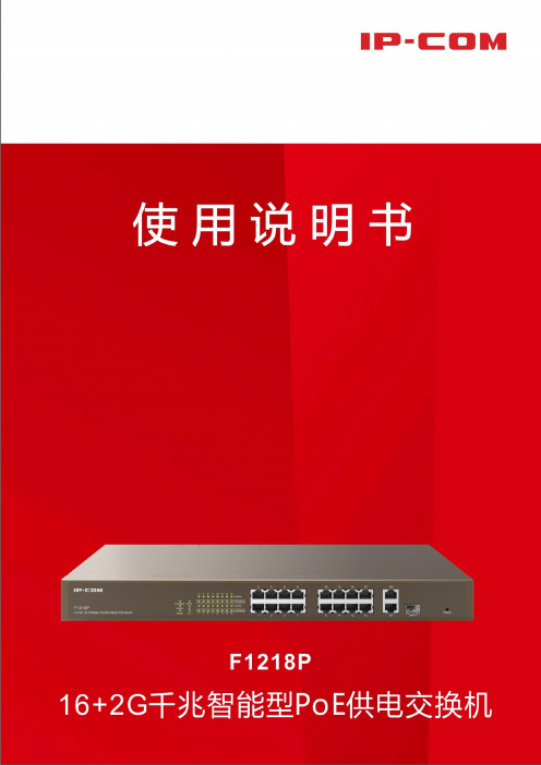
F1218PV1.0-C01说明书-电子档
iii
目录
1 产品介绍 ....................................................................................................................................... 1 1.1 简介 ............................................................................................................................................... 2 1.2 包装 ............................................................................................................................................... 2 1.3 外观 ............................................................................................................................................... 2 1.3.1 前面板.................................................................................................................................... 2 1.3.2 后面板.................................................................................................................................... 4 2 安装设备 ....................................................................................................................................... 5 2.1 安装注意事项 ............................................................................................................................... 6 2.1.1 安全措施................................................................................................................................ 6 2.1.2 环境要求................................................................................................................................ 6 2.1.3 工具准备................................................................................................................................ 7 2.2 设备安装 ....................................................................................................................................... 7 2.2.1 机架安装................................................................................................................................ 7 2.2.2 桌面安装................................................................................................................................ 8 2.3 连接保护地线 ............................................................................................................................... 9 2.3.1 安装环境中有接地排 ............................................................................................................ 9 2.3.2 安装环境中无接地排 .......................................................................................................... 10 2.4 连接电源 ..................................................................................................................................... 10 2.5 连接接口线缆 ............................................................................................................................. 11 2.5.1 连接 RJ45 端口 .................................................................................................................... 11 2.5.2 连接 SFP1 端口 .................................................................................................................... 12 2.6 上电启动 ..................................................................................................................................... 13 2.6.1 上电前检查 .......................................................................................................................... 13 2.6.2 给设备上电 .......................................................................................................................... 13
CDMA手机伴侣用户手册20101216

产品使用说明书网络连接指南

产品使用说明书网络连接指南【产品使用说明书】网络连接指南第一章:引言感谢您购买我们的产品。
本使用说明书旨在为您提供关于产品网络连接的详细指南。
请在使用产品之前仔细阅读本指南,并按照指示进行操作,以便您能够顺利连接产品到网络并享受其全部功能。
第二章:准备工作在开始网络连接之前,请确保您已经完成以下准备工作:1. 确认网络条件:产品需要连接到一个可用且稳定的网络环境,如家庭无线局域网(Wi-Fi)或以太网。
请检查您的网络是否能够满足产品的连接要求。
2. 获取网络信息:您需要准备好您的网络名称(SSID)和密码。
这些信息通常可以在您的无线路由器或网络提供商提供的文件或设备上找到。
第三章:无线网络连接大多数产品支持无线网络连接。
请按照以下步骤连接您的产品到无线网络:1. 打开产品:首先,请确保您的产品已经正常开机。
2. 进入设置菜单:在产品的主界面上找到“设置”选项,并点击进入。
3. 找到网络选项:在设置菜单中,您需要寻找类似于“网络设置”、“无线设置”或“Wi-Fi设置”的选项。
具体名称可能因产品型号不同而有所差异。
4. 扫描可用网络:在网络设置菜单中,您应该能够找到一个“扫描网络”或“搜索网络”的选项。
点击该选项,系统将为您列出附近可用的无线网络。
5. 选择您的网络:在扫描结果中,会显示出附近可用的无线网络列表。
请找到您的网络名称(SSID),并点击选择。
6. 输入密码:根据页面提示,输入您的网络密码。
请确保密码的准确性,并注意大小写。
7. 连接到网络:在输入正确的密码后,产品将尝试连接到您的无线网络。
请耐心等待片刻,直到连接成功。
8. 网络连接成功:一旦连接成功,您将会看到一个提示,确认您的产品已经成功连接到无线网络。
第四章:有线网络连接对于某些产品而言,您可以选择使用有线网络连接。
以下是连接到有线网络的步骤:1. 准备有线连接器:请找到产品包装中附带的网线(可能称为RJ-45电缆)。
2. 插入网线:将网线的一端插入产品的网络端口,另一端插入您的路由器或网络开关的可用端口。
中国万网 万网邮箱伴侣 说明书

万网邮箱伴侣用户使用手册通道加密+内容加密打造立体安全确保邮件收发无“泄”可击中国万网目录引言 (4)1.1编写目的 (4)1.2定义 (4)2简介 (4)2.1邮件伴侣产生的背景 (4)2.2邮件伴侣的功能及特点 (4)3兼容性 (5)3.1支持操作系统 (5)3.2支持的应用软件 (5)3.3支持的浏览器 (5)4使用过程 (5)4.1安装软件 (5)4.2启动软件 (9)4.3软件界面操作 (9)4.3.1新用户注册操作 (9)4.3.2下载用户密钥操作 (10)4.3.3用户功能启动 (11)4.3.4加密功能的使用 (12)4.3.5解密功能的使用 (13)4.3.6设置 (15)4.4Outlook界面操作 (18)4.4.1Outlook加密功能 (18)4.4.2Outlook解密功能 (19)4.4.3Outlook设置功能 (19)4.5页面界面操作 (19)4.5.1临时在线解密功能 (19)4.5.2Webmail网页功能操作 (21)4.6关于邮件伴侣 (22)4.7退出 (22)图表目录图1安装初始化界面 (5)图2邮件伴侣安装语言选择界面 (6)图3软件开始安装界面 (6)图4邮件伴侣系统注册信息及安装选项界面 (6)图5安装目录选择界面 (7)图6正在安装界面 (7)图7邮件伴侣证书安装界面 (8)图8证书验证确认安装界面 (8)图9安装结束界面 (9)图10软件登录界面 (9)图11软件注册新用户界面 (9)图12下载用户密钥界面 (10)图13下载用户密钥完成界面 (11)图14用户功能界面 (12)图15加密功能界面 (13)图16正文加密后图示 (13)图17正文解密界面 (14)图18正文解密后图示 (14)图19常规设置项界面 (15)图20备份设置项界面 (16)图21密钥口令修改设置项界面 (17)图22软件登录界面 (18)图23 OUTLOOK自动加密状态(左图)、取消自动加密后状态(右图) (18)图24 OUTLOOK邮件伴侣设置界面 (19)图25临时在线解密登录页面 (20)图26临时在线解密图示 (21)图27万网企业邮箱自动加密图示 (21)引言1.1编写目的本文档主要介绍了邮件伴侣的功能用途、运行环境、安装与初始化,同时也详细地描述了系统每个功能点的运行操作的具体过程。
爱国者移动伴侣客户端软件使用说明CHSV21
爱国者移动伴侣客户端软件使用说明V2.1目录免责声明: (3)特别提示: (4)一、设备的准备与连接 (4)1.1开机 (4)1.2 WiFi信号的连接 (4)1.2.1 Windows 平台 (4)1.2.2 iOS 平台 (6)1.2.3 Android 平台 (9)1.3 移动网络存储服务器(移动NAS)模式 (14)二、客户端软件的安装 (14)2.1 Windows 平台 (14)2.2 iOS 平台 (16)2.3 Android 平台 (18)三、Windows客户端软件的界面说明 (24)四、iOS、Android客户端软件的界面说明 (26)五、使用第三方软件进行访问 (51)免责声明:由于产品的更新,本手册中的图片和文字可能与您的设备中显示的图文略有不同,某些细微的变更将不会影响您的操作,请以实物操作为主。
一、感谢您购买爱国者移动伴侣产品。
在使用本产品之前,请认真阅读快速使用说明和本说明书。
当您开始使用爱国者移动伴侣产品时,爱国者电子认为您已经认真阅读了本说明书。
二、本产品为移动存储产品,用于用户数据的冗余备份,请用户在使用过程中及时对其中的数据进行备份。
我公司仅对产品的硬件部分承担售后责任。
如由于使用本产品造成数据丢失,我公司将依据售后相关规定进行提供相应的保换或保修服务,但是不负责恢复故障产品中保存的数据,不承担由此造成的任何恢复费用以及追加赔偿。
如果用户因保密要求需要保留或彻底销毁存储介质,应在享受保换或保修服务的同时支付相应的费用。
敬请用户谅解。
三、本文中涉及到的iOS、Android、Oplayer、Goodplayer等均为第三方公司所有。
四、硬件设备的生产厂家一般以1000为进制计算容量,即1KB=1000 Bytes, 1M=1000K, 1G=1000M;而微软操作系统是以1024为进制计算容量,1KB=1024 Bytes, 1M=1024K, 1G=1024M,格式化后的实际容量会少一些。
联想 移动伴侣 说明书
说 明警告:您可以使用移动伴侣中的“系统恢复”恢复整个硬盘(或C:盘)上的数据到出厂状态,包括出厂时的操作系统及为用户预装的各种软件。
此项操作一旦执行,将无法重新回到执行本操作前的状态。
执行完此项操作后,硬盘(或C:盘)上原先所有数据将全部丢失。
因此在此项操作执行前,请务必将有用的文件备份,比如备份到其他的硬盘或软盘、移动硬盘等。
如果是恢复C:盘,也可以将C:盘上的有用数据备份到其他分区。
注意:为了可靠有效地实现移动伴侣的各项功能,硬盘在出厂前已经划分出一块约为3G的分区,用以存放硬盘镜像文件以及移动伴侣程序文件。
出于安全考虑,这块分区是隐含的,在BIOS及操作系统中均不可见。
所以无论在BIOS中还是在操作系统中,您所看到的硬盘空间会比标准值小3G左右,具体数值取决于您的计算机出厂时的硬盘镜像文件的大小。
进入移动伴侣:情况一 开机或将计算机重启后,当屏幕上出现昭阳图标时,请按下F12键;情况二 如果PhoenixBIOS Setup Utility 里的Main菜单中的选项Boot-time Diagnostic Screen 设置为“[Enable]”,则在开机或将计算机重启后,当屏幕上出现开机信息时,请按下F12键。
多媒体文件在硬盘上的存放位置:移动伴侣可以播放硬盘上的电影、音乐、图片,请将您要欣赏的内容分别放在X:\Data\video、X:\Data\music、X:\Data\photo这三个文件夹下,其中X:指的是硬盘的根驱动器,可以为C:盘或者为D:盘,建议您选择D:盘。
影碟播放支持的视频文件格式:DVD、VCD、SVCD、MPG文件、VOB文件音乐播放支持的音频文件格式:CD、MP2、MP3图片浏览支持的格式:BMP、JPG、GIF、TIF、PCX、TGA、XPM、XBM、PPM简介让您不用进入Windows系统即可观看影片,欣赏音乐和浏览图片。
摆脱系统束缚,开机速度更快。
轻松一按,即进入影音播放状态。
联网产品使用指南

联网产品使用指南嵌入式设备联网解决方案版权©2008 上海卓岚信息科技有限公司保留所有权力ZL DUI 20081127.1.0版权©2008 上海卓岚信息科技有限公司保留所有权力版本信息对该文档有如下的修改:修改记录日期版本文档编号修改内容2008-11-27 Rev.1 ZL DUI 20081127.1.0 发布版本2009-8-16 Rev.2 ZL DUI 20081127.1.0 更新版本2014-5-24 Rev.3 ZL DUI 20081127.1.0 更新版本所有权信息未经版权所有者同意,不得将本文档的全部或者部分以纸面或者电子文档的形式重新发布。
本文档只用于辅助读者使用产品,上海卓岚公司不对使用该文档中的信息而引起的损失或者错误负责。
本文档描述的产品和文本正在不断地开发和完善中。
上海卓岚信息科技有限公司有权利在未通知用户的情况下修改本文档。
目录1.概述 (5)2.ZLV IRCOM的安装 (5)2.1.ZLVircom (5)2.2.工具软件 (5)3.硬件连接 (6)3.1.串口连接 (6)3.2.网口连接 (7)4.产品简单使用 (7)4.1.设备搜索 (7)4.2.参数设置 (8)4.3.透传通信 (9)4.4.虚拟串口 (11)5.型号与功能 (14)5.1.命名规则 (14)5.2.型号与功能 (16)10.参数设置 (17)10.1.参数含义 (17)10.2.修改参数方法 (22)10.2.1.ZLVirCom方式 (22)10.2.2.Web浏览器 (22)11.产品高级使用 (24)11.1.Modbus TCP转RTU (24)11.1.1.识别网关功能 (24)11.1.2.启用Modbus网关 (24)11.2.不同工作模式和参数 (25)11.2.1.UDP模式 (25)11.2.2.TCP模式 (26)11.2.3.对联方式 (27)11.3.跨Internet监控设置 (28)11.3.1.动态域名系统 (29)11.3.2.端口映射 (30)11.3.3.设备配置 (32)11.3.4.多串口的Internet配置 (34)11.4.多主机功能 (35)12.售后服务和技术支持 ................................................ 错误!未定义书签。
无线显示伴侣说明书

无线显示伴侣使用说明书目录产品介绍 (1)无线快速投影 (1)多种联网方式 (1)多种终端支持 (1)多向控制管理 (1)任意屏幕批注 (1)高清影音分享 (1)1 连接与启动 (2)2 产品设置 (3)2.1 通过产品使用界面设置 (3)2.1.1 基本设置 (4)2.1.2 显示设置 (4)2.1.3 网络设置 (5)2.1.4 语言设置 (8)2.1.5 系统信息 (8)2.2 通过Web管理页面设置 (9)2.2.1 系统状态 (9)2.2.2 系统设置 (10)2.2.3 重启设备 (10)3 无线实时投影 (10)3.1 在Windows下使用 (10)3.1.1 客户端下载 (10)3.1.2 开始投影 (11)3.1.3 使用批注 (14)3.1.4 任务栏菜单 (14)3.2 在Mac OSX下使用 (15)3.2.1 客户端下载 (15)3.2.2 开始投影 (17)3.3 从无线显示伴侣界面连接 (18)3.4 通过Web页面管理多人投影秩序 (19)4 无线媒体分享 (20)4.1 通过客户端软件使用 (20)4.2 通过第三方应用软件使用 (20)5 我的文件 (21)6 网页浏览 (21)疑难解答 (22)产品介绍无线显示伴侣实现了多用户以无线方式接入同一显示设备的应用需求。
配合产品提供的多向控制、屏幕批注、高清播放等功能特色,能够充分满足商务会议、教育培训等多个领域的应用场景。
无线快速投影产品通过独有的多媒体编解码和投影控制技术,实现了您的设备无线快速投影至显示设备的功能。
无需担心您的设备接口是否匹配线材,方便您在投影时自由就座。
多人切换使用时,免去了频繁插拔连线的困扰。
多种联网方式产品支持多种网络工作方式。
既可使用内置的无线热点独立工作,也可利用现有的网络接入,甚至还可以作为无线路由器使用,适用于各种不同的网络环境。
多种终端支持产品支持Windows、Mac OSX、Android、iOS等终端设备的投影接入,覆盖了主流的系统平台和设备类型。
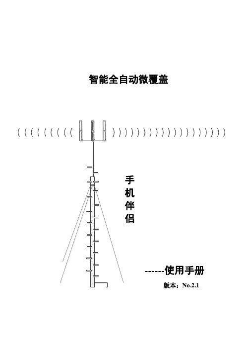
手机伴侣产品使用手册
b) 手机伴侣主机的可采用壁挂、平放、粘贴安装方式。先将天线设备上的线缆 按照施工规范引至主机要安装的位置,接在 BTS 口,重发外置天线接在 ANT 口,再接入电源。
技术创新 应用创新 3
全自动智能微覆盖
手机伴侣使用手册
6. 配件清单
名称 施主八木天线 手机伴侣主机 电源适配器 魔术贴
数量 1 1 1 2
技术创新 应用创新 4
全自动智能微覆盖
手机伴侣使用手册
4) 两天线之间尽量隔墙,距离拉开。禁止收发两天线在视距 10 米之内开启设备, 否则会工作不正常。 5) 在设备接入电源的 1 分钟内请勿使用手机在设备附近接打电话,否则会影响设 备正常工作。
————高速智能关断 高速伪自激筛选 高速自激自动消除 上行底噪抑制指示 支持输出分支通信
3. 指标
图一工作原理图 图二产品外观图
项目
技术指标
制式
CDMA/GSM/DCS/WCDMA/FDD
增益
65/70dB
噪声系数
≦6dB
带内平坦
≦6dB (p-p)
自动增益调整范围 >30dB
最大输出功率
17/20/23/27±2dBm
产品总重量
0.6 Kg
平均功耗
<5W
技术创新 应用创新 2
全自动智能微覆盖
4. 指示灯说明
手机伴侣使用手册
工作指示灯
状态
说明
灭
施主与重发天线之间的隔离度>62dB(±2dB)
隔离度指示灯
0.3 秒快闪
施主与重发天线之间的隔离度在 57~62dB(±2dB)
IOS (红)
1 秒慢闪
施主与重发天线之间的隔离度在 52~57dB(±2dB)
连接网络应用软件版本10.1.2发布说明书
Document Release Date:July2022 Software Release Date:July2022Legal noticesCopyright notice©Copyright2022Micro Focus or one of its affiliates.The only warranties for products and services of Micro Focus and its affiliates and licensors(“Micro Focus”)are as may be set forth in the express warranty statements accompanying such products and services.Nothing herein should be construed as constituting an additional warranty.Micro Focus shall not be liable for technical or editorial errors or omissions contained herein.The information contained herein is subject to change without notice.Documentation updatesThe title page of this document contains the following identifying information:l Software Version number,which indicates the software version.l Document Release Date,which changes each time the document is updated.l Software Release Date,which indicates the release date of this version of the software.To check for updated documentation,visit https:///documentation/connected/. SupportVisit the MySupport portal to access contact information and details about the products,services,and support that Micro Focus offers.This portal also provides customer self-solve capabilities.It gives you a fast and efficient way to access interactive technical support tools needed to manage your business.As a valued support customer,you can benefit by using the MySupport portal to:l Search for knowledge documents of interestl View software vulnerability alertsl Enter into discussions with other software customersl Manage software licenses and support contractsl Submit and track service requestsl Contact customer supportl View information about all services that Support offersMany areas of the portal require you to sign in.If you need an account,you can create one when prompted to sign in.To learn about the different access levels the portal uses,see the Access Levels descriptions.ContentsRelease Notes4 Enhancements4 Limitations5 Open issues6Installation8 List of Stable IPs8Release NotesConnected Web Application10.1.2This document is an overview of the changes made to Micro Focus Connected WebApplication10.1.2.It contains important information about the following items,which other documentation does not include:l Enhancementsl Limitationsl Open issuesl InstallationFor information about the installation requirements and compatibility of this release with other products,see the associated Micro Focus Connected Web Application Support Matrix.The support matrix may be updated between releases,so it is available only from the Connected documentation site.EnhancementsThis section describes the enhancements in this release.For more information about a specific one, see the Connected Help Center or contact Micro Focus Support.Customer branding.Provides the option to brand the Web Application application.To configure the customer branding,you need to provide the Product name and Company name.Currently,the branding changes are applied on notification emails(for example,welcome mail, password re-set mail,device migration,user status change and so on),emailed reports,and copyright information on the Web Application UI.New specialized roles.Two new specialized roles-Support Technician and Group Support Technician-manage groups,users and restores for users within their customer and group-level, respectively.The new roles cannot delete users and groups.Enhanced restore request option(Windows Only).Provides the option to select whether to inherit Access Control List(ACL)or not when restoring a file.By default,this option is enabled. Disabling this option will not restore original file ownership details nor the ACL impacting file security. Agent configuration policy.Provides new option to hide Exit and Access web console menu options in Agent.LimitationsThis section describes the limitations in this release.For more information about a specific one, contact Micro Focus Support.Issue:You cannot view H.264-encoded MPEG-4files using a Chrome browser.(TT-16665) Chrome browsers do not support these types of files.Workaround:Use a browser that supports H.264-encoded MPEG-4files to view the file.Issue:When viewing the web application in portrait mode using a Safari browser on an iPad running iOS9or later,the font in some dialog boxes appears too large.(TT-18185)Workaround:To reset the font to its correct size,rotate the iPad to landscape mode and use it in that orientation.Issue:Windows10:While managing backups,the web application displays an error if you select the drive that serves as the System Reserved Partition.(TT-19125)Although Connected does not support the backup of items on the System Reserved Partition,it displays the drive for selection.If you select this drive,the web application displays a message that it cannot connect to the Agent.Issue:You cannot create a user who has the same email address as a user whose status is pending delete.(TT-20565)Workaround:To reuse the email address of a user who is pending delete,reactivate the deleted user,change their email address,and then delete the user again.Now that the email address is no longer associated with a Connected user,you can assign it to someone else.Issue:The Connected internal IdP fails to authenticate users if the customer is assigned to a partner five levels deep in the Connected hierarchy.(TT-21521)Although Connected supports partners up to five levels deep,its internal IdP supports authentication for only four levels.Workaround:To ensure that Connected can authenticate users when using its internal IdP,create partners for those customers at a maximum of four levels deep from the top of the Connected hierarchy.Issue:Due to an issue with Microsoft Edge build38.14393and later,when you open a drop-down list and then scroll the page with the scrollbar,the list of items remains in its original position until you refresh the page.(TT-28469/EdgeHTML issue#14978262)Workaround:To ensure that the Edge browser moves the contents of an open drop-down list correctly,scroll the page with the mouse wheel instead of the scroll bar.Alternatively,use a different browser to view the application.Issue:Due to an issue with FireFox version65.0and later,the web application displays an empty text box followed by the text“lebowskilebowski”in the upper left corner under the header.(TT-28616) Workaround:To prevent these items from appearing,use a different browser to access the web application.Open issuesThis section describes the open issues in this release.For more information about a specific one, contact Micro Focus Support.Issue:When you click on user with On-Hold status,you get an error message:The user does not exist.(517026)Issue:You cannot share files with a recipient whose email address contains more than50 characters.(TT-10670)If you try to share files with a recipient whose email address contains more than50characters,the web application fails to share the files with any specified recipient and displays the error message: Invalid argument provided.Please verify that provided argument is valid. Workaround:Find out if the person has an alternative email address that contains less than50 characters.If so,use that address to share the file.Issue:Occasionally,closing the file view by pressing Esc prevents you from immediately viewing the same file again.(TT-10687)If you press Esc to close the file view and then immediately try to view the file again,the web application does not always redisplay the file.Workaround:To resolve the problem,either view another file before trying to view the first file again or refresh the page through the browser.Issue:The web application displays charts and graphs in Microsoft PowerPoint files upside down. (TT-16472)Issue:You cannot view large videos stored in Connected.(TT-16903)If you attempt to view a video file larger than approximately100MB,the web application displays an error message.Workaround:To view a large video stored in Connected,download the file,and then play the video locally.Issue:When using Internet Explorer11on touch-screen devices,you cannot resize custom images for collaboration files.(TT-17986)The zoom function in the Custom Image Selection wizard does not work on touch-screen devices when using Internet Explorer11.Workaround:Do one of the following:l Choose a custom image of32x32pixels,which you do not have to resize.l Use a different type of browser so that you can resize the image.Issue:The Policy Audit report sometimes identifies a policy as being applied to the Whole Company when it actually applies only to one or more specific groups.(TT-20519)Issue:Web Application displays"Internal Server Error"instead of a more descriptive message if it authenticates users against your own corporate identity provider(IdP)that is configured to prevent external access to the web application.(TT-20725)Issue:The Data Trends report does not include data from collaborations.(TT-21132)If you select multiple types of data for the report,including collaborations,the results do not contain collaboration data.If you select only collaborations,the results state"No data available".Issue:Under certain scenarios that are still to be determined,Connected generates a duplicate device for the same hardware.(TT-32379)When this occurs,the user cannot migrate the duplicated device.If you encounter this issue,contact Support for help to manually remediate it.InstallationTo access the Connected web application,use the URL to the server that hosts your Connected environment:l https://l https://l https://l https://l https://If you aren't sure which URL to use,contact your partner or the software fulfillment group that created your corporate Connected account.To install the Connected Key Management Server(KMS)software required in environments using customer-managed keys,see the Connected Key Management Server Install Guide,available from the Connected documentation site.List of Stable IPsThe following table lists the stable IPs:。
- 1、下载文档前请自行甄别文档内容的完整性,平台不提供额外的编辑、内容补充、找答案等附加服务。
- 2、"仅部分预览"的文档,不可在线预览部分如存在完整性等问题,可反馈申请退款(可完整预览的文档不适用该条件!)。
- 3、如文档侵犯您的权益,请联系客服反馈,我们会尽快为您处理(人工客服工作时间:9:00-18:30)。
附件4:中国移动“上网伴侣”产品使用说明书(文字版,设计版随宣传物料下发)1、“上网伴侣”是什么?“上网伴侣”是一个便携式宽带无线装置,大小仅相当于一张信用卡,它是可以将3G网络信号(将来的4G上网伴侣还支持4G网络)转换成您使用的手机、pad、笔记本电脑都通用的WIFI信号。
您走到哪里,WIFI宽带就跟您到哪里!2、“上网伴侣”适合什么样用户?适合于经常在各城区移动上网、有多个不同终端(包括手机、pad、笔记本电脑等)需要共享上网的用户。
3、“上网伴侣”和家庭有线宽带、3G网卡有什么区别?家庭宽带一般是有线固定形式、不能移动、不能带出去,较不方便。
“上网伴侣”是移动WIFI、无线宽带,非常方便。
3G网卡每次仅能针对一台笔记本电脑使用。
“上网伴侣”不仅支持多种终端接入,更支持多个终端同时接入。
“上网伴侣”依托广泛的3G高速网络,最快下载速度可达2.8M/S,最快上传速度达2.2M/S,您走到哪里、宽带就跟您到哪里。
此外,不仅您的电脑、ipad、手机可以同时上网,你也可以分享给周围的亲友。
4、我买了“上网伴侣”设备,该怎么使用?简单来说,完成以下三步即可开始上网冲浪:第一步:首先检查您的设备是否插入专属SIM卡。
第二步:按下电源键进行开机,约等30-60秒完成启动。
若无法启动请先检查是否已充好电。
第三步:设备启动成功后,打开支持WLAN的手机、平板电脑(如IPAD)、笔记本电脑,搜索到指定wifi信号并输入密码即可(一般WIFI信号名称及密码或在包装/设备背面、或在SIM插槽边)。
图示专属SIM卡插槽WIFI信号标识、密码在设备背面连接成功,其WIFI 2表示已连接2台设备按住电源启动,再等30-60秒5、三档套餐那个适合我?●30元含2G流量套餐,满足用户浏览新闻、玩微博、适量下载及在线视频的需求。
●60元含5G套餐,可满足用户较多游戏和软件下载、长时间在线视频。
●100元10G套餐,满足用户移动办公、视频聊天、长时间在线视频等各类上网。
6、上网流量是怎么算的?●1G=1024M●看网页、查资讯:一般0.1-0.2M/1个网页●刷微博:一般10-100K/个微博●挂股票:约10-50M/小时●在线视频:一般100-500M/部7、套餐流量万一用完了怎么办?会不会产生高额费用?“上网伴侣”套餐外资费为0.05元/M,流量不足200M、50M和0M的时候都会通过短信进行提醒,同时,还提供按周使用提醒服务。
若您需要去省外漫游,需要事先拨打10086开通,并选择全国漫游优惠包。
8、3G网络覆盖图郑重说明:我公司3G网络覆盖不断增多,具体以中国移动浙江公司网站信息为准/10086/td/hot/(1)【浙江省3G网络整体覆盖图】目前已覆盖11个地市的88个城区、县和发达乡镇地市覆盖区域杭州主城区、武林拱墅江干滨江下沙萧山余杭西湖临安富阳淳安桐庐建德湖州吴兴南浔德清安吉长兴嘉兴嘉禾嘉善平湖海盐海宁桐乡金华婺城区武义县浦江县磐安县兰溪市义乌市东阳市永康市金东区丽水莲都区青田龙泉缙云遂昌云和景宁松阳庆元衢州衢城开化常山龙游江山绍兴越城柯桥上虞诸暨嵊州新昌台州椒江黄岩路桥温岭临海三门玉环天台仙居城区和郊区35省道沿线乡镇舟山定海普陀宁波主城区、海曙江北江东鄞州北仑镇海宁海慈溪余姚奉化象山温州核心城区、苍南乐清龙湾鹿城瓯海平阳瑞安泰顺文成永嘉洞头(2)【杭州地区3G网络整体覆盖图】县区覆盖区域主城杭州主城区北以杭州绕城公路为界,南以狮闻线为界,东以风情大道为界,西以G2501为界区包括:拱墅区、武林区、西湖区、江干区、滨江区、下沙区六个区,北靠余杭区、东临萧山区,西接富阳、临安市萧山北以观十五线为界,南以S019为界,东以信益线为界,西以风情大道为界余杭南以高桦线为界,西以霞大线为界,北以S13为界,东以临东路为界临安东以汪宫线为界,西以吉浙线为界,南以洪里线为界,北以S013为界,,昌化镇、太阳龙岗镇、于潜镇富阳北以S002为界,西以S016为界,南以Y窈塔线为界,东以戴尖线为界桐庐主要覆盖为桐庐县城主城区包括古城和新城区,杭新景高速荻蒲到桐庐城区路段连续覆盖。
新城区:G320为界西北至富春江,桐庐宝新路为界西南,桐庐乔林路为界东北;古城区:西以305为界以东,东北以天目路为界西南方向,东南以开元街为界西北方向。
建德建德连续覆盖区域为建德主城区。
东至环城北路与江滨路交叉口,以严州大道为界西北,以新安东路为界东南淳安主城区基本实现连续覆盖。
东起S302与S302交叉口,西至新安北路;北起浪排线,南至南山大街。
(3)【宁波地区3G网络整体覆盖图】县区覆盖区域主城宁波主城区东至学院路,西至盛莫路,北至江北连接线和北环西路,南起环城南路,上述封闭区区域TD室外信号基本保证北仑东起骆下公路,西至富春江路,北至迎宾路,南至29国道慈溪东起东三环北路,西至西外环路,北至中横线,南至29国道奉化东至甬临线,西至西环路,北至大成东路,南至岳林东路宁海东起滨海中路,西至山河路,北起时代大道,南至纺织东路象山东起巨鹰路,西至城西路,北至靖南大街,南至滨海大道余姚东起城东路,西至西环路,北起丰山路,南至西环南路镇海东起沿江东路,西至环城西路,北至雄镇路,南至沿江西路(4)【温州地区3G网络整体覆盖图】县区修改主城区北至望江东路,南至南白象,西至戴宅路,东至涌江路为界盖。
瑞安北至温瑞大道罗梅线,南至飞云江大桥滨海大道,东至G104瑞安大桥线,西至甬台温高速沿线为界乐清西到龙湾大桥头,南到黄华,北到雁荡山灵峰搬迁,东到南塘为界平阳北至平阳104国道孙楼村,南至鳌江瓯南大道,西至高铁沿线,东至瑞平北路为界苍南东到宜山区域,南到灵溪路段,北到龙港区域瓯南大桥,西到104国道龙湾北至灵昆高速路口,南至海城人民北路,东至滨海大道,西至会展路大学城南至茶山镇,东至南柳,北至南大线,西至南白象为界永嘉南到阳光大道,北到永嘉北渡头,西到五星大道,东到乌牛码道为界(5)【绍兴地区3G网络整体覆盖图】县区覆盖区域越城区南至二环南路、东至二环东路、北至群贤路、西至二环西路区域内柯桥104国道以北、轻纺城大道以北、华齐路以南,滨海洋江路以北、越兴路以西、三江路以南区域齐贤镇镇中心诸暨环城南路以北、东二环路以西、北二环路以南、杭金衢高速以东区域,枫桥镇、山下湖镇、店口镇、次坞镇嵊州甬金高速以北、北艇路以南区域区域内新昌环城南路、西昌南路、104国道、东昌路封闭区域(6)【台州地区3G网络整体覆盖图】县区覆盖区域椒江西至黄椒路东至机场路,北至江滨路,南至开发大道,区域内,周边三家、洪家、下陈主干道和中心区域黄岩西至甬台温高速,东至二环东路,北至104国道,南至二环南路区域内,黄岩郊区、西至开发区,新前,东至江口镇,南至院桥,主干道和中心区域路桥路桥城区,西至财富大道,东至路泽太一级公路,北至双水路,南至路院一级公路,路桥郊区,西至桐屿,南至峰江,横街,东至金湑三门三门县城南至224省道,北至环城中路,东至环城东路,西至环城南路,健跳,六敖基本覆盖镇中心,镇中心天台天台县城北至上山高速公路,南至104国道,东至工人路区域内,天台郊区,省道062至平桥镇主干道,以及平桥镇中心玉环北至迎宾路,西至玉大线,南至海港路,东至富港路;沙门工业区,陈屿开发区基本覆盖镇中心温岭西至沈海高速公路,南至南环路,北至泽新线,东至椒新线;新河,箬横,松门,石塘基本覆盖镇中心临海临海城区西至江滨西路,南至104国道,北至东方大道,东至临近甬台温高速公路区域;临海郊区,杜桥镇,杜桥化工区,四岔基本覆盖镇中心仙居仙居县城北至大庙前村,南至台金高速,东至永安公园,西至台金高速入口区域;仙居郊区,35省道城区至横溪镇主干道,以及各乡镇政府所在地连续覆盖(7)【嘉兴地区3G网络整体覆盖图】县区覆盖区域嘉禾北起320国道,东至双溪路,南至二环南路,西至320国道区域内,周边新塍镇、城西工业园区、余新镇、城东大桥村的中心区域海宁北起兴隆路,东至海昌路,南至海宁城南菜场,西至嘉海公路区域内,许村、盐官海盐北起海兴路、东至新桥北路、南至河滨西路,西至城西路区域内,秦山嘉善北起外环东路,东至施家南路,南至人民大道,西至体育南路区域内西塘基本覆盖镇中心平湖北起福臻路,东至东湖大道,南至当湖西路,西至平湖大道区域内桐乡北起体育路,东至世纪大道,南至环城南路,西至环城西路区域内,濮院镇中心乌镇基本覆盖镇中心,镇中心其他崇福、王店镇、王江泾基本覆盖镇中心,镇中心(8)【金华地区3G网络整体覆盖图】县区覆盖区域金华市区东以东二环路为界;西以西二环路、白龙桥工业区为界;北以北二环路为界,外含孝顺镇、曹宅镇上的小量站点;南以330国道为界,义乌东以甬金高速高速公路、环城东线为界;西以沪昆高速公路、环城西路为界;北以城北路、商城大道为界;南以甬金高速公路为界。
浦江东以永在大道为界;西毛亚线为界;北以月泉西路、月泉东路为界;南以以S047省道为界。
东阳西以城南西路为界,东以迎宾大道为界,北以横店镇、南马镇为界,南以甬金高速公路为界,,横店镇,南马镇以覆盖本乡镇为主永康西以西塔路、环城西路为界,东以花园大道为界,北以城北路、330国道为界,南以城南路为界。
武义西以44省道与43省道连接处为界,东以东升东路、明招路为界,北以环城北路为界,南以中盛路为界。
磐安西以花月路为界,东以螺山路为界,北以文溪北路为界,南以月山路为界。
兰溪西以环城西路为界,东以环城东路为界,北以文溪北路为界,南以西山路为界。
(9)【湖州地区3G网络整体覆盖图】县区覆盖区域湖州市区北起杨丘线,南至南线公路,西至成业路,东至经七路区域内安吉北起上马岭,南至阴山脚,东起营盘山,西至东湾。
长兴北起齐山路,南至潘家浜,东起经四路,西至梅花庄。
德清北起三桥,南至俞家坑,东起双山路,西至职业高中南浔北起申苏浙皖高速,南至曹家湾,东起虹阳路,西至南浔大道。
(10)【衢州地区3G网络整体覆盖图】县区覆盖区域主城区东以上大线、东港三路为界;西以大桥支路、花大线、白云山路为界;北以杭金衢、清泰外国语学校;南以廿里、大洲为界。
龙游东以沪昆高速公路、学士路、城南路为界;西以环城西路为界;北以凤坤路、茂盛路为界;南以祥云路、人民南路为界。
常山东以白马路、文峰东路为界;西以新都西大道、新都东大道为界;北以文坊路为界;南以龙江路、定阳南路为界。
江山西以礼贤路、南门路、环城西路为界,东以江东大道、通达路为界,北以北环路为界南以江贺路为界。
开化西以桃下线、城华线为界,东以江滨北路、古溪路为界,北以芹北路为界,南以园三路、园一路为界。
(11)【丽水地区3G网络整体覆盖图】县区覆盖区域主城区北至环城北路,东至环城东路,南至环城南路、水阁区,西至括苍路、三岩寺景宁北至城北村,东至红星路,南至水三段808乡道,西至金仙路。
