AZ984-1C-12D中文资料
AZ943-1CH-12DE中文资料
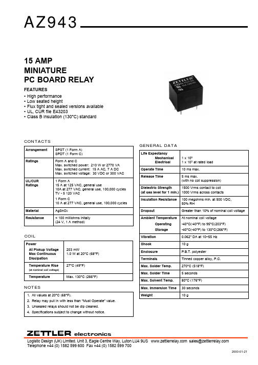
CONTACTSArrangement SPST (1 Form A)SPDT (1 Form C)RatingsForm A and CMax. switched power: 210 W or 2770 VA Max. switched current: 15 A AC, 7 A DCMax. switched voltage: 30 VDC or 300 VAC UL/CUR 1 Form ARatings15 A at 125 VAC, general use10A at 277 VAC, general use, 100,000 cycles TV - 5 120 VAC1 Form C10 A at 277 VAC, general use, 100,000 cyclesMaterial AgSnO 2Resistance< 100 milliohms initally (24 V, 1 A method)ZET TLERelectronicsTelephone +44 (0) 1582 599 600 Fax +44 (0) 1582 599 700Logistic Design (UK) Limited. Unit 3, Eagle Centre Way, Luton LU4 9US sales@ 2000-01-21GENERAL DATALife ExpectancyMechanical 1 x 10⁶Electrical 1 x 10⁵at rated load Operate Time 10 ms max.Release Time5 ms max.(with no coil suppression)Dielectric Strength 1500 Vrms contact to coil (at sea level for 1 min.)1000 Vrms across contacts Insulation Resistance 100 megohms min. at 500 VDC,50% RHDropoutGreater than 10% of nominal coil voltage Ambient TemperatureAt nominal coil voltage Operating -40°C(-40°F) to 95°C(203°F)Storage-40°C(-40°F) to 130°C(266°F)Vibration 0.062" DA at 10–55 Hz Shock10 gEnclosure P.B.T. polyesterTerminalsTinned copper alloy, P.C.Max. Solder Temp.270°C (518°F)Max. Solder Time 5 seconds Max. Solvent Temp.80°C (176°F)Max. Immersion Time 30 seconds Weight10 gCOILPowerAt Pickup Voltage 203 mWMax Continuous 1.0 W at 20°C (68°F)Dissipation Temperature Rise27°C (49°F)(at nominal coil voltage)TemperatureMax. 130°C (266°F)15 AMP MINIATUREPC BOARD RELAYFEATURES •High performance •Low seated height•Flux tight and sealed versions available •UL, CUR file E43203•Class B insulation (130°C) standardNOTES1.All values at 20°C (68°F).2.Relay may pull in with less than “Must Operate” value.3.Unsealed relays should not be dip cleaned.4.Specifications subject to change without notice.2000-01-21ZET TLERelectronicsTelephone +44 (0) 1582 599 600 Fax +44 (0) 1582 599 700Logistic Design (UK) Limited. Unit 3, Eagle Centre Way, Luton LU4 9US sales@ RELAY ORDERING DATASTANDARD RELAYSCOIL SPECIFICATIONSORDER NUMBERNominal CoilMax. ContinuousCoil ResistanceMust OperateUnsealed Sealed VDC VDC ±10%VDC 58.3703.8AZ943–1CH–5D AZ943–1CH–5DE 610.0100 4.5AZ943–1CH–6D AZ943–1CH–6DE 915.0225 6.8AZ943–1CH–9D AZ943–1CH–9DE 1220.04009.0AZ943–1CH–12D AZ943–1CH–12DE 1830.090013.5AZ943-1CH-18D AZ943-1CH-18DE 2440.01,60018.0AZ943–1CH–24D AZ943–1CH–24DE 4867.06,20036.0AZ943–1CH–48DAZ943–1CH–48DESubstitute “1AH” in place of “1CH” to indicate 1 Form A contact.Dimensions in inches with metric equivalents in parentheses. Tolerance: ± .010"。
中国日本美国钢材牌号对比表
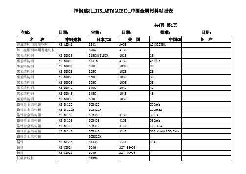
日期: 神钢建机
KS ASS41
审核: 日本JIS
SS41 SGDA S15C或S15CK SS41B S20C S25C S30C S35C S40C S45C S50C SCM420 SCM420H SCM430 SCM435 SCM440 SCM445 SCM822H SM443 SC46 SC49 SWRM6 SWRM10
日期: 美
A-36 A48CINo30A A48CINo35A A48CINo40A A48CINo45A A536 60-40-18 A536 65-45-12 A536 80-55-06 A536 80-55-06 1541 1541H
批准: 国 中国GB
Q235A或A3
日期: 备 注
日期: 神钢建机
KS TKM13A KS TOKS3 KS TOKT2
审核: 日本JIS
STKM13A STS35 STPG38 STPG38-E STPG38-S SGP-E SGP-L C1220T C2600T C2600P C3604BD C4641BD SUJ2 SK5 SUP3 SUP6 SUP7 SUP10 SUS 304 SWRH 42A SWP-A
日期: 美
A-36 A-36 1015 A-36 1020 1025 1030 1035 1040 1045 1050 20CrMo 15 A3或C3 20 25 30 35 40 45
批准: 国 中国GB
A3或Q235A
日期: 备 注
20CrMoA 4130 4135 4140 4145 1541 A27 65-35 A27 70-36 近似于Q195AF 30CrMo 35CrMo 40CrMoA 50CrMoA或12Cr3MoA 45Mn
9841碳控仪说明书
10 (1) 停电前仪表处于工作完成的复位状态时--------------------------------10 停电前仪表处于运行状态,现希望从停电前的中断点接续工作时--- 10 (2) 停电前仪表处于运行状态,现要重新选定工艺编号或从头开始 运行时-------------------------------------------------------------- 10 2 运行后各数码管显示的内容------------------------------------------------------ 11 (1) 自动控制(闭环)工作状态的调节方式------------------------------------11 (2) 手动控制(碳势开环)工作状态的调节方式------------------------------11
七、工艺及控制参数库的调用、检查、输入修改及存储-------------------- 12 1 各项参数代号及输入数据规格表------------------------------------------------ 12 (1) 选工艺编号(自动水平0)---------------------------------------------------- 12 (2) 编制自动控制工艺(自动水平1) ------------------------------------------ 12 (3) 设定自动控制控制参数 (自动水平2)----------------------------------- 13
EVAL-LT8641A-AZ Demo Manual

EVAL-LT8641A-AZ Demo Manual65V, 3.5A/5A Peak SynchronousStep-Down Silent Switcher© 2023 Analog Devices, Inc. All rights reserved. Trademarks and registered trademarks are the property of their respective owners.General DescriptionEvaluation circuit EVAL-LT8641A-AZ is a 65V, 3.5A/5A peak synchronous step-down Silent Switcher ® with spread spectrum frequency modulation featuring the LT ®8641A . The demo board is designed for 5V output from a 5.5V to 65V input. The wide input range allows a variety of input sources, such as automotive batteries and industrial supplies. The LT8641A is a compact, ultralow emission, high efficiency, high speed synchronous monolithic step-down switching regulator. Top and bottom power switches, compensation components, and other necessary circuits inside the LT8641A minimize external components and simplify design. The special Silent Switcher architecture minimizes EMI emissions. The selectable spread spectrum mode can further improve EMI performance. Ultralow 2.5μA quiescent current in Burst Mode ® operation achieves high efficiency at very light loads. Fast minimum on-time of 35ns enables high V IN to low V OUT conversion at high frequency. The LT8641A switching frequency can be programmed either through oscillator resistor or external clock over a 200kHz to 3MHz range. The default frequency of the evaluation board is 2MHz. The SYNC pin on the evaluation board is grounded by JP1 for low ripple burst mode operation. Move JP1 to PULSE SKIPPING positionto change the operation mode to pulse-skipping operation. Once JP1 is on SPREAD SPECTRUM position, V CC is applied to the SYNC pin for low EMI spread spectrum operation. To synchronize to an external clock, move JP1 to SYNC and apply the external clock to the SYNC turret. Figure 1 shows the efficiency of the circuit at 12V and 24V input in Burst Mode operation. Figure 2 shows EMI performances of the board (with EMI filter). The red lines in Figure 2 are CISPR25 Class5 peak limit. The figure shows that the circuit passes the test with a wide margin. To achieve EMI/EMC performance, as shown in Figure 2, the input EMI filter is required, and the input voltage should be applied at the V EMI turret.The LT8641A data sheet gives a complete description of the part, operation, and application information. Read the data sheet in conjunction with this user guide for EVAL-LT8641A-AZ. The LT8641A is assembled in a 3mm × 4mm plastic QFN package with exposed pad for low thermal resistance. The layout recommendations for low EMI operation and maximum thermal performance are available in the “Low EMI PCB Layout and Thermal Considerations” and “Peak Output Current” sections of the data sheet.Performance Summary Specifications are at T A = 25°C Analog Devices | 2Typical Performance CharacteristicsFigure 1. LT8641A Eval Circuit Efficiency vs. Load Current(2MHz Switching Frequency, Burst Mode)(V EMI = 14V, V OUT = 5V, I OUT = 3.5A, 2MHz Switching Frequency) Analog Devices | 3Quick Start ProcedureThe evaluation board EVAL-LT8641A-AZ is easy to set up to evaluate the performance of the LT8641A. See Figure 3for proper measurement equipment setup and follow this procedure.1.Set an input power supply capable of 65V/5A.2.With power off, connect the input power supplyto V EMI and GND.3.With power off, connect the loads from V OUT toGND.4.Place the voltmeters across the output voltagesense terminals V OUT_SENSE and GND to getaccurate output voltage measurements.5.Turn on the power at the input.Note: Make sure that the input voltage does not exceed 65V.6.Check for proper output voltages. Regulate theoutput at 5.0V (±4%).Note: If there is no output, temporarily disconnect the load to make sure the load is not set too high.7.Once the proper output voltage is established,adjust the load within the operating ranges andobserve the output voltage regulation, ripplevoltage, efficiency, and other parameters. Note: When measuring the input or output voltage ripple, take care to avoid a long ground lead on the oscilloscope probe. Measure the output voltage ripple by touching the probe tip directly across the output capacitor. See Figure 4 for the proper scope technique.8.An external clock can be added to the SYNCterminal when SYNC function is used (JP1 onthe SYNC position). Ensure the chosen RT setsthe LT8641A switching frequency to equal orbelow the lowest SYNC frequency. Refer to thedata sheet section “Synchronization and SpreadSpectrum”. Analog Devices | 4 Analog Devices | 5Figure 3. Proper Measurement Equipment SetupFigure 4. Scope Probe Placement for Measuring Input or Output Voltage RippleBill of Materials Analog Devices | 6Schematic Diagram Analog Devices | 7Revision HistoryInformation furnished by Analog Devices is believed to be accurate and reliable. However, no responsibility isassumed by Analog Devices for its use, nor for any infringements of patents or other rights of third parties thatmay result from its use. Specifications subject to change without notice. No license is granted by implication orotherwise under any patent or patent rights of Analog Devices. Trademarks and registered trademarks are theproperty of their respective owners.w w w.a n a l o g.c o m Analog Devices | 8。
CKFZR-12D负荷开关带接地刀带熔夹

CKFZR-12D真空式高压负荷开关产品信息:各种型号负荷开关
企业简介
•企业机构:上海红申(控股)电气有限公司
•法人代表:刘经理
•注册资本:人民币5000万
•经营模式:合资、生产加工、经销批发
•员工数量:800 -1200人
•主要市场:大陆;西欧;东南亚
•客户类型:国家电网公司、成套厂、大中型建筑工程•所属行业:配电输电设备、开关
•产品信息:成套大类(高低压电器、变压器、箱变)
产品信息:
•1、CKFZ-12D真空式负荷开关
•2、CKFZR-12D真空式负荷开关
•3、TEC-VSARC意大利技术真空式负荷开关•4、HS-VSARC意大利技术真空式负荷开关
1、CKFYR-12D压气式负荷开关---A
7、箱变(配电箱、配电柜、成套大类)-1
企业荣誉、企业文化。
CTA91AS12VDC4A资料
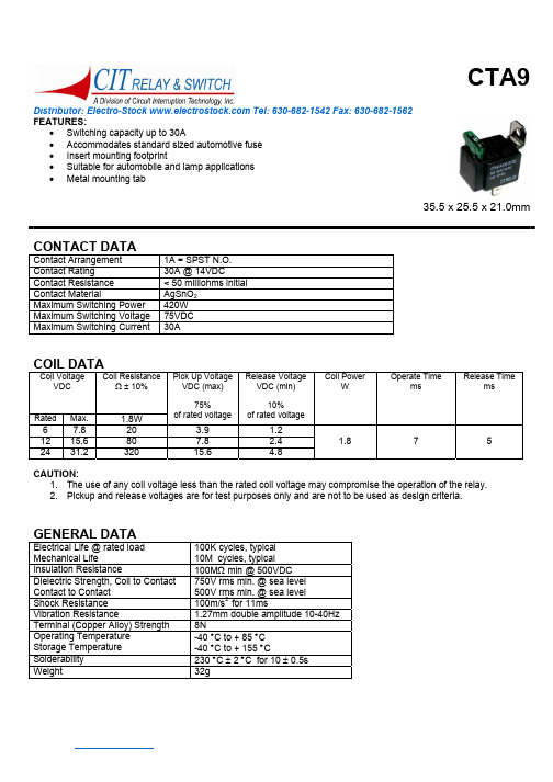
35.5 x 25.5 x 21.0mm
CONTACT DATA
Contact Arrangement Contact Rating Contact Resistance Contact Material Maximum Switching Power Maximum Switching Voltage Maximum Switching Current 1A = SPST N.O. 30A @ 14VDC < 50 milliohms initial AgSnO2 420W 75VDC 30A
元器件交易网
CTA9
Distributor: Electro-Stock Tel: 630-682-1542 Fax: 630-682-1562
ORDERING INFORMATION
1. Series: CTA9 2.Contact Arrangement: 1A = SPST N.O. 3. Sealing Options: S = Sealed 4. Coil Voltage: 6VDC 12VDC 24VDC 5. Fuse Options: 3A 4A 5A 7-1/2A 10A 15A 20A 25A 30A
GENERAL DATA
Electrical Life @ rated load Mechanical Life Insulation Resistance Dielectric Strength, Coil to Contact Contact to Contact Shock Resistance Vibration Resistance Terminal (Copper Alloy) Strength Operating Temperature Storage Temperature Solderability Weight 100K cycles, typical 10M cycles, typical 100MΩ min @ 500VDC 750V rms min. @ sea level 500V rms min. @ sea level 100m/s2 for 11ms 1.27mm double amplitude 10-40Hz 8N -40 °C to + 85 °C -40 °C to + 155 °C 230 °C ± 2 °C for 10 ± 0.5s 32g
阿特拉斯枪样本
气路附件
180
安装向导........................................................................... 181 安全原则........................................................................... 183 球阀.................................................................................. 184 空气处理单元.................................................................... 185 直接润滑单元.................................................................... 193 快速接头........................................................................... 195 爪形接头........................................................................... 207 旋转接头........................................................................... 208 转接头............................................................................... 209 气管爆裂保护器.................................................................211 气管.................................................................................. 212 螺旋气管........................................................................... 214 吹尘枪............................................................................... 215 平衡器............................................................................... 216 卷管器............................................................................... 218 测试工具........................................................................... 222 安装建议........................................................................... 223
海士卡基立方冰块机零配件清单说明书
No.4253 No.248
CONT Plug UK & MIDDLE EAST OCEANIA CHINA
DCM-120KE-P DCM-120KE-P
FT10416F0 FT20416F0 FST0508F0 P02552-01 263224M01 264001M01 376454M01 377811M01 376455M01 420470-06 427902-05 427902-04 FSK0408S0 259891P01 P02697-01 P02698-01 P02760-01 P00193-01 448949-01 121899M01 121900M01 121901M01 FSG0408S0 121228P01 341489G01 376725M01 121230P02 379018M01
50Hz 50Hz / 60Hz
50Hz 50Hz 50Hz 50Hz 50Hz 50Hz / 60Hz 50Hz 50Hz
Auxiliary Codes
Auxiliary Code Breakdown
The auxiliary code is the first two characters in the serial number. The first character indicates the year. Years progress or regress in alphabetical order. The series runs from "A" through "V" and the letters "I" and "O" are skipped. The second character indicates significant part changes within a year. Base is "0" and this number advances for each change. In cases where there is a letter in parentheses, this designates the month. This is the last character in the serial number. The series runs from "(A)" through "(M)" and the letter "(I)" is skipped. This designation is only included when identifying a parts change within an auxiliary code.
AZ、DC零件号对照表3

224 1700N-057
25 1700N-063
26 1700N-064
27 1700N-066
28 1700N-067
29 1700N-071
30 1700N-072
31 1700N-086
32 1700N-093
33 1700N-117
34 1700N-138
AZ9003906001 AZ9003876312 AZ2229210601 AZ2229016007 AZ9003346430 AZ9003340401 AZ2229286001 AZ9003076002
AZ9003072018 AZ2203220201 AZ2229220014 AZ2229220015
活塞回位弹簧 气动助力器总成
输出轴球轴承6317X3N 行星架推力轴承AXK91113 输出轴油封
三倒挡齿轮滚针轴承座圈 主轴锁紧螺母 二三挡齿座
一倒挡齿座 键
变速器中间壳体
副轴 倒挡常啮合齿轮 杯形倒挡垫圈
倒挡从动齿轮 主轴低挡齿轮 低倒挡拨叉
2/3挡导块 4/5挡导块 小盖壳体(双杆)
换档头
选档杆总成
130 DC16J200T-137
AZ2229030115 AZ2210100201 AZ2210100202 AZ2210100206 AZ2203100233 AZ2203100235 AZ2210100208 AZ2210100210 AZ2210100207 AZ2210020332 AZ2210030338 AZ2210030337 AZ2210040719 AZ2229020020 AZ2229036002 AZ9003997003 AZ2229050005 AZ2229010013 AZ2229100206 AZ2229010011 AZ2229210602 AZ2229220013
AZ2150-1A-12DE中文资料
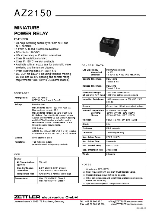
ZET TLERelectronics GmbHFax +49 89 800 97 200 office@ 0 97 800 89 +49 Tel. GermanyPuchheim, D-82178Junkersstrasse 3, 2003-03-12GENERAL DATALife ExpectancyMinimum operations Mechanical 1 x 10⁷Electrical 1 x 10⁵at 30 A 120 VAC Res. (N.O.)Operate Time (max.)Max. 12 ms Typical: 8 ms Release Time (max.)Max. 5 ms Typical: 3.5 msDielectric Strength 2500 Vrms contact to coil(at sea level for 1 min.)1500 Vrms between open contacts Insulation Resistance 1000 megohms min. at 500 VDC, 20°C 50% RHDropoutGreater than 10% of nominal coil voltage Ambient TemperatureAt nominal coil voltageOperating -55°C (-67°F) to 85°C (185°F)Storage -55°C (-67°F) to 105°C (221°F)Vibration 0.062" (1.5 mm) DA at 10–55 Hz Shock 20 gEnclosure P .B.T. polyester TerminalsTinned copper alloy Max. Solder Temp.270°C (518°F)Max. Solder Time 5 seconds Max. Solvent Temp.80°C (176°F)Max. Immersion Time30 seconds Weight25 gramsMINIATURE POWER RELAYFEATURES•30 Amp switching capability for both N.O. and N.C. contacts•1 Form A, B and C contacts available •DC coils to 120 VDC•Life expectancy to 10 million operations •Class B insulation standard•Class F (155°C) version available•Available with an epoxy seal for automatic wave soldering and immersion cleaning •Proof Tracking Index (PTI/CTI) 175•UL, CUR file E44211 including versions meeting UL 508 and UL 873 spacing and contact rating requirements; VDE 132710 ÜG (some models)CONTACTSArrangement SPDT (1 Form C)SPST (1 Form A and 1 Form B)RatingsResistive load:Max. switched power:900 W or 7200 VA Max. switched current: 30 AMax. switched voltage: 30 VDC or 300 VAC UL Rating:See chart for UL contact ratings.AZ2150 Series meets UL 508 Group A spacing and UL 873 refrigeration and safety control requirements. AZ2151 Series meets UL 508Group B spacing requirements.VDE Rating:AZ2150-1A - 25 A at 250 VAC, 1 x 10⁴, resistive AZ2150-1C - 20 A at 250 VAC, 1 x 10⁴, resistiveMaterial Silver cadmium oxideResistance< 20 milliohms initially(at rated current, voltage drop method)COILPowerAt Pickup Voltage 500 mW(typical)Max. Continuous 2.2 W at 20°C (68°F) ambient Dissipation 1.8 W at 40°C (104°F) ambient Temperature Rise 43°C (77°F) at nominal coil voltage TemperatureMax. 130°C (266°F) Class B Max. 155°C (311°F) Class FNOTES1.All values at 20°C (68°F).2.Relay may pull in with less than “Must Operate” value.3.Unsealed relays should not be dip cleaned.4.Other coil resistances and sensitivities available upon request.Please call the factory.5.Specifications subject to change without notice.2003-03-12ZET TLERelectronics GmbHFax +49 89 800 97 200 office@ 0 97 800 89 +49 Tel. GermanyPuchheim, D-82178 Junkersstrasse 3, RELAY ORDERING DATASTANDARD RELAYS: 1 Form A (SPST); 508 Group A; UL 873 VersionCOIL SPECIFICATIONS ORDER NUMBER*Nominal Max.CoilMust Coil Continuous Resistance Operate Unsealed SealedVDC VDC±10%VDC57.327 3.75AZ2150–1A–5D AZ2150–1A–5DE 68.940 4.5AZ2150–1A–6D AZ2150–1A–6DE 913.997 6.75AZ2150–1A–9D AZ2150–1A–9DE 1217.51559.0AZ2150–1A–12D AZ2150–1A–12DE 1522.525611.25AZ2150–1A–15D AZ2150–1A–15DE 1827.438013.5AZ2150–1A–18D AZ2150–1A–18DE 2436.166018.0AZ2150–1A–24D AZ2150–1A–24DE 4868.42,56036.0AZ2150–1A–48D AZ2150–1A–48DE 70104.45,50052.5AZ2150–1A–70D AZ2150–1A–70DE 110163.213,45082.5AZ2150–1A–110D AZ2150–1A–110DESTANDARD RELAYS: 1 Form A (SPST); UL 508 Group B VersionCOIL SPECIFICATIONS ORDER NUMBER*57.327 3.75AZ2151–1A–5D AZ2151–1A–5DE 68.940 4.5AZ2151–1A–6D AZ2151–1A–6DE913.997 6.75AZ2151–1A–9D AZ2151–1A–9DE1217.51559.0AZ2151–1A–12D AZ2151–1A–12DE1522.525611.25AZ2151–1A–15D AZ2151–1A–15DE1827.438013.5AZ2151–1A–18D AZ2151–1A–18DE2436.166018.0AZ2151–1A–24D AZ2151–1A–24DE4868.42,56036.0AZ2151–1A–48D AZ2151–1A–48DE70104.45,50052.5AZ2151–1A–70D AZ2151–1A–70DE 110163.213,45082.5AZ2151–1A–110DAZ2151–1A–110DE * Substitute “1B” or “1C” in place of the “1A” to indicate 1 Form B and 1 Form C respectively.To indicate Class F version, add suffix “F”.MECHANICAL DATA。
BZX84C12V中文资料
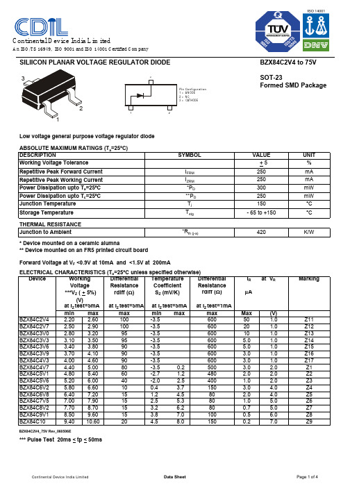
SILIICON PLANAR VOLTAGE REGULATOR DIODEBZX84C2V4 to 75V SOT-23Formed SMD PackageLow voltage general purpose voltage regulator diode ABSOLUTE MAXIMUM RATINGS (T a =25°C)UNIT %Repetitive Peak Forward Current mA Repetitive Peak Working Current mA mW mW °C °CTHERMAL RESISTANCE K/W* Device mounted on a ceramic alumna** Device mounted on an FR5 printed circuit boardELECTRICAL CHARACTERISTICS (T a =25°C unless specified otherwise) Device Temperature DifferentialI R at V RMarkingCoefficient ResistanceS Z (mV/K)rdiff (Ω)µAat I Z test=5mA at I Z test=1mAmin max min max max Max (V)BZX84C2V4 2.20 2.60 -3.560050 1.0Z11BZX84C2V72.50 2.90 -3.560020 1.0Z12BZX84C3V0 2.80 3.20 -3.560010 1.0Z13BZX84C3V3 3.10 3.50 -3.5600 5.0 1.0Z14BZX84C3V6 3.40 3.80 -3.5600 5.0 1.0Z15BZX84C3V9 3.70 4.10-3.56003.0 1.0Z16BZX84C4V34.00 4.60 -3.5600 3.0 1.0Z17BZX84C4V7 4.40 5.00 -3.5 0.2500 3.0 2.0Z1BZX84C5V1 4.80 5.40 -2.7 1.2480 2.0 2.0Z2BZX84C5V6 5.20 6.00 -2.0 2.5400 1.0 2.0Z3BZX84C6V2 5.80 6.60 0.4 3.7150 3.0 4.0Z4BZX84C6V8 6.407.20 1.2 4.580 2.0 4.0Z5BZX84C7V57.007.90 2.5 5.380 1.0 5.0Z6BZX84C8V27.708.70 3.2 6.2800.7 5.0Z7BZX84C9V18.509.60 3.8 7.01000.5 6.0Z8BZX84C109.4010.604.5 8.01500.27.0Z9BZX84C2V4_75V Rev_060506E*** Pulse Test 20ms < tp < 50ms1515152060401015909090801001009595 + 5VALUE max I ZRM Storage Temperature T stg Junction to Ambient*R th (j-a)DESCRIPTIONI FRM Working Voltage Tolerance Power Dissipation upto T a =25ºC SYMBOL *P D ***V Z ( + 5%)(V)at I Z test=5mA Resistance rdiff (Ω)at I Z test=5mA250420300- 65 to +150250Forward Voltage at V F <0.9V at 10mA and <1.5V at 200mAVoltage 150250Differential Working Power Dissipation upto T c =25ºC **P D Junction Temperature T j Pin Configuration1 = A N ODE2 = N C3 =CATHODE12Continental Device India LimitedAn ISO/TS 16949, ISO 9001 and ISO 14001 Certified CompanySILIICON PLANAR VOLTAGE REGULATOR DIODEBZX84C2V4 to 75V SOT-23Formed SMD PackageELECTRICAL CHARACTERISTICS (T a =25°C unless specified otherwise) Device Temperature DifferentialI R at V RMarkingCoefficientResistanceS Z (mV/K)rdiff (Ω)µAat I Z test=5mAat I Z test=1mA min max min max max Max (V)BZX84C1110.4011.60 5.4 9.01500.18Y1BZX84C1211.4012.70 6.0 101500.18Y2BZX84C1312.4014.10 7.0 111700.18Y3BZX84C1513.8015.60 9.2 132000.0510.5Y4BZX84C1615.3017.10 10.4 142000.0511.2Y5BZX84C1816.8019.10 12.4 162250.0512.6Y6BZX84C2018.8021.20 14.4 182250.0514.0Y7BZX84C2220.8023.30 16.4 202500.0515.4Y8BZX84C2422.8025.60 18.4 222500.0516.8Y9at I Z Test=2mA at I Z Test=0.5mABZX84C2725.1028.90 21.4 25.33000.0518.9Y10BZX84C3028.0032.00 24.4 29.43000.0521.0Y11BZX84C3331.0035.00 27.4 33.43250.0523.1Y12BZX84C3634.0038.00 30.4 37.43500.0525.2Y13BZX84C3937.0041.00 33.4 41.23500.0527.3Y14BZX84C4340.0046.00 37.6 46.63750.0530.1Y15BZX84C4744.0050.00 42.0 51.83750.0532.9Y16BZX84C5148.0054.00 46.6 57.24000.0535.7Y17BZX84C5652.0060.00 52.2 63.84250.0539.2Y18BZX84C6258.0066.00 58.8 71.64500.0543.4Y19BZX84C6864.0072.00 65.6 79.84750.0547.6Y20BZX84C7570.0079.0073.4 88.65000.0552.5Y21BZX84C2V4_75V Rev_060506E*** Pulse Test 20ms < tp < 50ms2002152402551301501701808080908025303070at I Z test=5mA at I Z test=5mA max at I Z test=2mAat I Z Test=2mA4045555520Resistance ***V Z ( + 5%)rdiff (Ω)(V)Forward Voltage at V F <0.9V at 10mA and <1.5V at 200mAWorking Differential Voltage Pin Configuration1 = A N ODE2 = N C3 =CATHODE12BZX84C2V4 to 75V SOT-23Formed SMD PackageSOT-23 Package Reel InformationReel specification for W" Packing (13" reel)BZX84C2V4_75V Rev_060506ESOT-23 Formed SMD PackageTape Specification for SOT-23 Surface Mount DeviceS O T -23 T &R3K /reel 10K /reel136 g m /3K p c s 415 g m /10K p c s3" x 7.5" x 7.5"9" x 9" x 9"13" x 13" x 0.5"12 K 51 K 10 K17" x 15" x 13.5"19" x 19" x 19"17" x 15" x 13.5"192 K 408 K 300 K12 k g s 28 k g s 16 k g sPACKAGEN e t W e i g h t /Q t y DetailsS T A N D A R D PACKI N N E R C A R T O N B O XQ t y O U T E R C A R T O N B O XQ t y G r W t SizeSizePacking Detail±0.0114.47.9 – 10.9T R A I L E RF I X I N GT A P EL E A D E R9.2±0.5MAXNOTES:No. of Devices8mm Tape Size of Reel 330 mm (13")10,000 Pcs 8mm Tape Size of Reel 180 mm (7")3,000 Pcs1.The bandolier of 330 mm reel contains at least 10,000 devices.2.The bandolier of 180 mm reel contains at least 3,000 devices.3.No more than 0.5% missing devices / reel. 50 empty compartments for 330 mm reel.15 empty compartments for 180 mm reel.4.Three consecutive empty places might be found provided this gap is followed by 6 consecutive devices.5.The carrier tape (leader) starts with at least 75 empty positions (equivalent to 330 mm).In order to fix the carrier tape a self adhesive tape of 20 to 50 mm is applied. At the end of the bandolier at least 40 empty positions (equivalent to 160 mm) are there.3.15Customer Notes BZX84C2V4 to 75VSOT-23Formed SMD Package1. CDIL Semiconductor Devices are RoHS compliant, customers are requested to pleasedispose as per prevailing Environmental Legislation of their Country.2. In Europe, please dispose as per EU Directive 2002/96/EC on Waste Electrical andElectronic Equipment (WEEE).BZX84C2V4_75V Rev_060506E DisclaimerThe product information and the selection guides facilitate selection of the CDIL's Semiconductor Device(s)best suited for application in your product(s)as per your requirement.It is recommended that you completely review our Data Sheet(s)so as to confirm that the Device(s)meet functionality parameters for your application.The information furnished in the Data Sheet and on the CDIL Web Site/CD are believed to be accurate and reliable.CDIL however,does not assume responsibility for inaccuracies or incomplete information.Furthermore,CDIL does not assume liability whatsoever,arising out of the application or use of any CDIL product;neither does it convey any license under its patent rights nor rights of others. These products are not designed for use in life saving/support appliances or systems.CDIL customers selling these products(either as individual Semiconductor Devices or incorporated in their end products),in any life saving/support appliances or systems or applications do so at their own risk and CDIL will not be responsible for any damages resulting from such sale(s).CDIL strives for continuous improvement and reserves the right to change the specifications of its products without prior notice.CDIL is a registered Trademark ofContinental Device India LimitedC-120 Naraina Industrial Area, New Delhi 110 028, India.Telephone + 91-11-2579 6150, 4141 1112 Fax + 91-11-2579 5290, 4141 1119email@ 。
三极管参数表
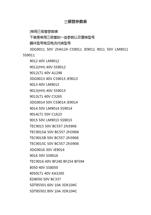
三极管参数表|常用三极管参数表下表是常用三极管的一些参数以及替换型号器件型号电压电流代换型号3DG9011 50V 2N4124 CS9011 JE9011 9011 50V LM9011 SS90119012 40V LM90129012(HH) 40V SS90129012LT1 40V A12983DG9013 40V CS9013 JE90139013 40V LM90139013(HH) 40V SS90139013LT1 40V C32653DG9014 50V CS9014 JE90149014 50V LM9014 SS90149014LT1 50V C16239015 50V LM9015 SS9015TEC9015 50V BC557 2N3906TEC9015A 50V BC557 2N3906TEC9015B 50V BC557 2N3906TEC9015C 50V BC557 2N39063DG9016 30V JE90169016 30V SS9016TEC9016 40V BF240 BF254 BF5948050 40V SS80508050LT1 40V KA3265ED8050 50V BC337SDT85501 60V 10A 3DK104CSDT85502 80V 10A 3DK104CSDT85503 100V 10A 3DK104DSDT85504 140V 10A 3DK104ESDT85505 170V 10A 3DK104FSDT85506 60V 10A 3DK104CSDT85507 80V 10A 3DK104CSDT85508 100V 10A 3DK104DSDT85509 140V 10A 3DK104EED8550 50V BC3378550 40V LM8550 SS85508550LT1 40V KA32652SA1015 50V BC177 BC204 BC212 BC213 BC251 BC257 BC307 BC512 BC557 CG1015 CG673 2SC1815 60V BC174 BC182 BC184 BC190 BC384 BC414 BC546 DG458 DG18152SC1815L 60V BC550 2SC2240 2S26742SC2675 2SC33782SC1815LT1 60V 9014LT12SC945 60V BC107 BC171 BC174 BC182 BC183 BC190 BC207 BC237 BC382 BC546 BC547 BC582 DG945 2N2220 2N2221 2N2222 3DG120B 3DG4312 MMBT3904 40V BCW72 3DG120C MMBT3906 40V BCW70 3DG120CMMBT2222 未知BCX19 3DG120CMMBT2222A 75V 3DK10CMMBT5401 160V 3CA3FMMBTA92 300V 3CG180HBC807 50V BC338 BC537 BC635 3DK14BBC807R 50V BCX17 BCX17R BCW68 BCW68R BC807-W 50V BCX17 BCW68 2SB1219ABC817 50V BCX19 BCW65 BCX66BC817R 50V BCX19 BCX19R BCW65 BCW65R BCX66 BCW66RBC817-W 50V BCX19 BCW65 BCW66 2SD1820 2SD1949BC846 80V BCV71 BCV72BC846R 80V BCV71 BCV71R BCV72 BCV72RBC846-W 80V BCV71 BCV72 BCV72RBC847 50V BCW71 BCW72 BCW81BC847R 50V BCW71 BCW71R BCW72 BCW72R BCW81 BCW81RBC847-W 50V BCW71 BCW72 BCW81 2SC4101 2SC4102BC848 30V BCW31 BCW32 BCW33 BCW71 BCW72 BCW81 BC848R 30V BCW31 BCW31R BCW32 BCW32R BCW33 BCW33R BCW71 BCW71R BCW72 BCW72R BCW81 BCW81R BC848-W 30V BCW31 BCW32 BCW33 BCW71 BCW72 BCW81 2SC4101 2SC4102 2SC4117BC856 50V BCW89BC856R 80V BCW89 BCW89RBC856-W 80V BCW89 2SA1507 2SA1527BC857 50V BCW69 BCW70 BCW89BC857R 50V BCW69 BCW69R BCW70 BCW70R BCW89 BCW89RBC857-W 50V BCW69 BCW70 BCW89 2SA1507 2SA1527BC858 30V BCW29 BCW30 BCW69 BCW70 BCW89BC858R 30V BCW29 BCW29R BCW30 BCW30R BCW69 BCW69R BCW70 BCW70R BCW89 BCW89RBC858-W 30V BCW29 BCW30 BCW69 BCW70 BCW89 2SA1507 2SA15272SA733 60V BC177 BC204 BC212 BC213 BC251 BC257 BC307 BC513 BC557 3CG120C 3CG4312 MMUN2111 50V UN2111 MUN2111 50V MMUN2111UN2111 50V FN1A4M DTA114EK RN24022SA1344MMUN2112 50V UN2112MUN2112 50V MMUN2112UN2112 50V FN1F4M DTA124EK RN24032SA1342MMUN2113 50V UN2113MUN2113 50V MMUN2113UN2113 50V FN1L4M DTA144EK RN24042SA1341MMUN2211 50V UN2211MUN2211 50V MMUN2211UN2211 50V DTC114EK FA1A4M RN14022SC3398MMUN2212 50V UN2212MUN2212 50V MMUN2212UN2212 50V DTC124EK FA1F4M RN14032SC3396MMUN2213 50V UN2213MUN2213 50V MMUN2213UN2213 50V DTC144EK FA1L4M RN14042SC33952SC3356 20V 2SC3513 2SC3606 2SC38292SC3838K 30V BF517 BF799 2SC3015 2SC3016 彩显中易损大功率三极管主要参数表型号功率(W) 反压(V) 电流(A) 功能BU208A 50 1500 5 电源开关管BU508A 75 1500 8 电源开关管BU2508AF 45 1500 8 行管*BU2508DF 125 1500 8 行管*BU2508D 125 1500 8 行管BU2520AF 45 1500 10 行管BU2520AX 45 1500 10 行管*BU2520DF 125 1500 10 行管BU2522AF 45 1500 10 行管*BU2522DF 80 1500 10 行管* BU2525DF 45 800 12 行管BUH515 60 1500 8 行管C1520 10 250 视放C1566 250 视放C1573 250 视放C1875 50 1500 电源开关管C3153 100 900 6 电源开关管C3026 50 1700 5 行管C3457 50 1100 3 电源开关管C3459 90 1100 电源开关管C3460 100 1100 6 电源开关管C3461 140 1100 8 行管*C3683 50 1500 5 行管C3686 50 1400 8 行管C3687 150 1500 8 行管C3481 120 1500 5 电源开关管C3688 150 1500 10 行管*C3883 50 1500 5 行管C3885 50 1400 7 行管C3886 50 1400 8 行管C3887 80 1400 7 行管C3888 80 1400 80 行管C3889 80 1400 80 行管*C3891 50 1400 6 行管*C3892 50 1400 7 行管*C3893 50 1400 8 行管C3895 60W 1400V 7A 行管C3896 70 1400 8 行管*C3897 180 1500 12 行管C3897 250 1500 25 行管C3998 250 1500 25 行管*C4122 60 1500 6 行管*C4124 70 1500 8 行管*C4125 70 1500 10 行管C4237 150 800 10 行管*C4269 60 1500 7 行管*C4293 50 1500 5 行管*C4294 50 1500 6 行管*C4589 50 1500 10 行管*C4742 50 1500 6 行管*C4744 50 1500 6 行管C4747 50 1500 10 行管*C4769 60 1500 7 行管C4770 60 1500 7 行管C5048 50 1500 12 行管C5088 45 1500 8 行管C5129 50 1500 6 行管C5148 50 1500 8 行管C5250 50 1500 8 行管C5297 60 1500 8 行管C5299 60 1400 8 行管C5339 50 1500 7 行管C5418 120 1500 6 行管*D1396 50 1500 2 行管*D1398 50 1500 5 行管D1402 120 1500 5 电源开关管D1403 120 1500 6 电源开关管*D1426 80 1500 行管*D1427 80 1500 5 行管*D1428 80 1500 6 行管D1433 80 1500 7 行管D1434 80 1500 5 行管*D1554 40 1500 行管D1555 50 1500 5 电源开关管*D1878 60 1500 6 行管*D1879 60W 1500V 5A 行管*D1880 70 1500 8 行管*D1881 70 1500 10 行管D1886 70 1500 8 行管D1887 70 1500 10 行管*D2125 50 1500 5 行管*D870 50 1500 5 行管功率Pcm/W 反压BVCBO 电流ICM/A (*带阻尼)进口与国产显示器常用三极管代换表型号可代用型号用途价格2SA562 CG673B、2SB689 预视放2SA670 2SA1069、2SB513 电源调整管2SA673 2SA719、2SA697 帧激励2SA715 3CF3A、2SB529 场输出管2SA778A 3CG21C、CG75-1AB 开关电源误差放大2SA778AK C3CG21G、CG75-1A 开关电源误差放大2SA844D 3CG21C、CG75-1AB 视放2SA844E 3CG21G 视放2SA940 CD568B 场输出管2SA6395 2SA778、2SA858 行激励管2SB337 B337 电源调整管2SB407 3L780 电源调整管2SB548 3CF3B、2SA794 场输出管2SB566AK CD77-1A、3CF5A 电源调整管2SB556K CD77-1A、3CF5B 电源调整2SB621 3CG23B、2SB1035 电源推动管2SC458 3DG4A、2SC664 行振荡2SC536 3DG4A、2SC2320 电源推动管2SC562 G6738、B689 预视放2SC633 3DG6B、2SC1684 行振荡管2SC634 3DG12B 行振荡管2SC643A D2027、2SD818 行输出管2SC680A 3DD205B、2SC1025 场输出2SC681 3DD102B、2SC901 行输出2SC734 3DX200B、2SC2274 行振荡管2SC828 3DG56B、2SC3330 电源误差放大管2SC935 3DD102D、2SD320 电源调整管2SC8937 D2027、2SD818 行输出管2SC1034 2SD818、2SD299 行输出管2SC1162 FA433A、2SC2068 场输出枕形校正2SC1172 D2027、2SD820 行输出管2SC1209 3DG12A、2SD734 电源误差放大管2SC1213 3DG130A、2SC2120 电源误差放大管2SC1213A 3DG12B、2SC1247A 电源误差放大2SC12143DA151A、2SC2002 枕形校正2SC1308 D209、2SD820 行输出管2SC1318 3DG12A、2SC2274 行激励管2SC1364 3DX2038、2SC2320 行激励管2SC1505 DA1722B、2SC1757 行视放2SC1507 DA1722B、2SC1756、2SC1757 行激励管2SC1364 3DX2038、C23020 行激励管2SC1520 DA1722B、2SC2068 预视放2SC1566 3DA151D、2SC1514 视放2SC1573 3DA87C、2SC1762 视放2SC1672 3DD102B、2SC2433 电源调整管2SC1685 3DD180、2SC1570 脉冲开关2SC1819 3DA151D、2SC2425 视放2SC1890A 3DA878、2SC2363 视放2SC1905 3DA151D、2SD1163 视放2SC1942 D209、2SD1401 行输出管2SC2233 3DD12B、2SC2373 行输出2SD201 3DD102A、2SD125A 电源调整管2SD226 3DD207、2SD315 电源调整管2SD299 D2027、2SC1308 行输出管2SD350 D2027、2SD348 行输出管2SD380 D209、2SD348 行输出管2SD869 2SD993、2SD898B 行输出管C3150 C3151、C3152 开关管BU508A BU508D、C3893、C3895、C3897 开关管彩显中易损场效应管主要参数表型号功率Pcm/W 最大电流IDM/A D-S极间耐压价格2SK534 100W 5A 800V2SK538 100 3 9002SK557 100 12 5002SK560 100 15 5002SK566 78 3 800 2SK644 125 10 500 2SK719 120 5 900 2SK725 125 15 500 2SK727 125 5 900 2SK774 120 18 500 2SK785 150 20 500 2SK787 150 8 900 2SK788 150 13 500 2SK790 150 15 500 2SK872 150 6 900 2SK955 150 9 800 2SK956 150 9 800 2SK962 150 8 900 2SK1019 300 30 500 2SK1020 300 30 500 2SK1081 125 7 800 2SK1082 125 6 800 2SK1117 100 6 600 2SK1118 45 6 600 2SK1119 100 4 1000 2SK1120 150 8 1000 2SK1171 240 5 1400 2SK1198 75 3 800 2SK1249 130 15 500 2SK1250 150 20 500 2SK1271 240 15 1400 2SK1280 150 18 500 2SK1281 120 4 700 2SK1341 100 5 900 2SK1342 100 8 900 2SK1357 125 5 900 2SK1358 150 9 900 2SK1451 120 5 900 2SK1498 120 20 500 2SK1500 160 25 500 2SK1502 120 7 900 2SK1507 50 6 600 2SK1512 150 10 850 2SK1531 150 15 500 2SK1537 100 5 900 2SK1539 150 10 900 2SK1563 150 12 500 2SK1649 100 6 900 2SK1794 150 6 900 2SK2038 125 6 900。
AZ2110-1A-12D中文资料

CONTACTSArrangementSPDT (1 Form C)SPST (1 Form A and 1 Form B)RatingsResistive load:Max. switched power: 900 W or 10000 VA Max. switched current: 40 A (Form A)30 A (Form B)Max. switched voltage: 30 VDC or 300 VAC UL Rating:See chart for UL contact ratings.AZ2150 Series meets UL 508 Group A spacing and UL 873 refrigeration and safety controlrequirements. AZ2151Series meets UL 508 Group B spacing requirements.VDE Rating:AZ2110-1A - 25 A at 250 VAC, 10k cycles, resis tiveAZ2110-1C - 20 A at 250 VAC, 10k cycles, resistiveMaterial Silver cadmium oxideResistance20 milliohms initially(at rated current, voltage drop method)COILPowerAt Pickup Voltage 500 mW(typical)Max. Continuous 2.2 W at 20°C (68°F) ambient Dissipation 1.8 W at 40°C (104°F) ambientTemperature Rise 38°C (68°F) at nominal coil voltage - AZ211033°C (59°F) at nominal coil voltage - AZ2120TemperatureMax. 130°C (266°F) Class B Max. 155°C (311°F) Class FGENERAL DATALife ExpectancyMinimum operations Mechanical 1 x 10⁷Electrical 1 x 10⁵at 30 A 120 VAC Res. (N.O.)Operate Time (max.)Max. 12 ms Typical: 8 ms Release Time (max.)Max. 5 ms Typical: 3.5 msDielectric Strength2500 Vrms contact to coil(at sea level for 1min)1500 Vrms between open contacts Insulation Resistance 1000 megohms min. at 500 VDC, 20°C,50% RHDropoutGreater than 10% of nominal coil voltage Ambient TemperatureAt nominal coil voltageOperating-55°C (-67°F) to 100°C (212°F) Class B -55°C (-67°F) to 125°C (257°F) Class F Storage-55°C (-67°F) to 130°C (266°F) Class B -55°C (-67°F) to 155°C (311°F) Class F Vibration 0.062" DA at 10–55 Hz Shock20 gEnclosure (optional)P .B.T. polyesterTerminalsTinned copper alloy, P.C. & quick connects,.250" wide, on topNote: Allow suitable slack on leads when wiring, and do not subject the terminals to excessive force.Max. Solder Temp.270°C (518°F)Max. Solder Time 5 seconds Weight40 gramsPOWER RELAYFEATURES•40 Amp switching capability•1 Form A, B and C contacts available •DC coils to 120 VDC •Low cost•Life expectancy to 10 million operations •High dielectric strength version available •Class B insulation standard•Class F (155°C) version available•Versatility of both PC and “Trace Saver” quick-connect terminals on contacts offered on the AZ2120 version •Proof Tracking Index (PTI/CTI) 175•UL, CUR file E44211 including versions meeting UL 508 and UL 873 spacing and contact rating requirements; VDE 132710ÜG (some models)NOTES1.All values at 20°C (68°F).2.Relay may pull in with less than “Must Operate” value.3.Other coil resistances and sensitivities available upon request. Please contact the factory.4.Specifications subject to change without notice.STANDARD RELAYS: UL 508: 1/8” Clearance, 1/4” CreepageCOIL SPECIFICATIONS ORDER NUMBER* Nominal Max.Coil MustCoil Continuous Resistance Operate Form A (SPST)Form C (SPDT)VDC VDC±10%VDC57.327 3.75AZ2110–1A–5D AZ2110–1C–5D68.940 4.5AZ2110–1A–6D AZ2110–1C–6D913.997 6.75AZ2110–1A–9D AZ2110–1C–9D1217.51559.0AZ2110–1A–12D AZ2110–1C–12D1522.525611.25AZ2110–1A–15D AZ2110–1C–15D1827.438013.5AZ2110–1A–18D AZ2110–1C–18D2436.166018.0AZ2110–1A–24D AZ2110–1C–24D4868.42,56036.0AZ2110–1A–48D AZ2110–1C–48D70104.45,50052.5AZ2110–1A–70D AZ2110–1C–70D 110163.213,45082.5AZ2110–1A–110D AZ2110–1C–110D STANDARD RELAYS: 1/16” Clearance, 1/8” CreepageCOIL SPECIFICATIONS ORDER NUMBER*57.327 3.75AZ2111–1A–5D AZ2111–1C–5D68.940 4.5AZ2111–1A–6D AZ2111–1C–6D913.997 6.75AZ2111–1A–9D AZ2111–1C–9D1217.51559.0AZ2111–1A–12D AZ2111–1C–12D1522.525611.25AZ2111–1A–15D AZ2111–1C–15D1827.438013.5AZ2111–1A–18D AZ2111–1C–18D2436.166018.0AZ2111–1A–24D AZ2111–1C–24D4868.42,56036.0AZ2111–1A–48D AZ2111–1C–48D70104.45,50052.5AZ2111–1A–70D AZ2111–1C–70D 110163.213,45082.5AZ2111–1A–110D AZ2111–1C–110D* Substitute “1B” in place of the “1A” to indicate 1 Form B contact. To indicate Class F version, add suffix “F”. For quick connect terminals on contacts substitute “2120” or “2121” in place of “2110” or “2111”.UL/CUR File E44211 Approved Contact RatingsForm A Form B Form CLoad Type Cycles Volts(NO)(NC)NO NCGeneral Purpose100,000125 or 240 VAC30 A15 A30 A15 A(Inductive)30,000277 VAC30 A30 A30 A30 AResistive100,000125 or 240 VAC30 A15 A30 A15 A100,00030 VDC20 A10 A20 A10 A100,000277 VAC20 A———100,000240 VAC15 A———6,000250 VAC40 A—40 A—Ballast6,000277 VAC 6 A 3 A 6 A 3 APilot Duty6,000125 VAC800 VA290 VA800 VA290 VA30,000125 VAC800 VA—690 VA—100,000125 VAC690 VA—470 VA275 VA6,000240 VAC1152 VA768 VA1152 VA768 VA100,000277 VAC764 VA—764 VA—Motor Load6,000125 VAC 1 HP1/4HP 1 HP1/4HP6,000240 VAC 3 HP 1 HP 2 HP 1 HP30,000125 VAC 1 HP— 1 HP—100,000125 or 277 VAC3/4HP—3/4HP—Definite Purpose30,000125 VAC96 LRA33 LRA60 LRA33 LRA30 FLA10 FLA20 FLA10 FLA(LRA-Locked Rotor)100,000125 VAC82.8 LRA—82.8 LRA—27 FLA—27 FLA—(FLA-Full Load)30,000240 VAC80 LRA33 LRA60 LRA33 LRA30 FLA10 FLA20 FLA10 FLA100,000277 VAC60 LRA—60 LRA—20 FLA—20 FLA—Tungsten6,000125 VAC15 A—15 A 3 A6,000240 VAC 5 A— 5 A 3 A6,000120 VAC— 3 A——6,000240 VAC— 3 A——TV–525,000120 VAC TV–5—TV–5TV–3TV–325,000120 VAC—TV–3—TV–3Note: See AZ2100 Data Sheet for more complete UL and CUR approved contact ratings.MECHANICAL DATADimensions in inches with metric equivalents in parentheses. Tolerance: ± .010"Coil Temperature Rise - AZ2120Coil Temperature Rise - AZ2110Maximum Switching Capacity。
铝合金材质成分

ADC12AD12铝合金ADC12是什么材料日本的铝合金牌号,又称12号铝料,Al-Si-Cu系合金,是一种压铸铝合金,适合盖子、缸体类等,执行标准为:JIS H 5302-2000《铝合金压铸件》。
ADC12相当于中国国产的合金代号YL113,合金牌号是YZAlSi11Cu3,执行标嘉?篏B/T 15115-1994《压铸铝合金》(该标准2002年就列入国家标准修订计划,国标计划项目编号20021029-T-604,但不知为何至今尚未完成)。
美国合金牌号是383,执行标准为:ASTM B 85-03 Standard Specification for Aluminum-Alloy Die Castings (可能还有比ASTM B 85-03更新的版本)常识日本的ADC10及ADC12,基本上是用废旧铝再生的,日本还制订出废铝再生压铸铝合金的标准。
当前国内广泛应用压铸合金Y112,依据机械工业部的压铸合金标准,比较适宜于用废铝来熔炼,这无疑可缓解铝锭供不应求的矛盾。
成分ADC12含铝(Al) 余量,铜(Cu)1.5~3.5,硅(Si)9.6~12.0,镁(Mg)≤0.3,锌(Zn)≤1.0,铁(Fe)≤0.9,锰(Mn)≤0.5,镍(Ni)≤0.5,锡(Sn)≤0.3[1][2]ADC10ADC10压铸铝合金【化学成分】ADC10含铝(Al) 余量,铜(Cu)2.0~4.0,硅(Si)7.5~9.5,镁(Mg)≤0.3,锌(Zn)≤1.0,铁(Fe)≤0.9,锰(Mn)≤0.5,镍(Ni)≤0.5,锡(Sn)≤0.3.ADC10压铸铝合金【性能】ADC10的铸造性、耐压性好,适合制造大型压铸件。
力学性能和切削性良好,但耐蚀性稍差。
【含硅量】ADC12铝合金属于Al-Si-Cu系合金,该系列合金有ADC10、ADC12,ADC10的铸造性、耐压性好,适于制造大型压铸件。
其力学性能和切削性好,但耐蚀性稍差。
孕穗-抽穗期高温下有机肥配合氮肥调控对糯稻产量和品质的影响

854㊀㊀2024年第65卷第4期收稿日期:2024-01-23基金项目:浙江省 三农九方 科技协作计划(2022SNJF006);浙江省水稻新品种选育重大科技专项资助(2021C02063-3);浙江省自然科学基金资助项目(LTGN23D010001);嘉兴市科技计划(2021AZ10014,2023AZ11004)作者简介:王保君(1990 ),男,山西繁峙人,农艺师,硕士,主要从事耕作制度与农业生态研究工作,E-mail:wbj19901012@㊂通信作者:张红梅(1976 ),女,内蒙古赤峰人,高级农艺师,硕士,从事农产品安全及污染物在土壤 植物系统中的迁移转化机制等研究工作,E-mail:147969664@㊂文献著录格式:王保君,程旺大,沈亚强,等.孕穗-抽穗期高温下有机肥配合氮肥调控对糯稻产量和品质的影响[J].浙江农业科学,2024,65(4):854-858.DOI:10.16178/j.issn.0528-9017.20231185孕穗-抽穗期高温下有机肥配合氮肥调控对糯稻产量和品质的影响王保君1,程旺大1,沈亚强1,陈贵2,张红梅1∗(1.嘉兴市农业科学研究院生态环境研究所,浙江嘉兴㊀314016;2.嘉兴市农业科学研究院生物技术研究所,浙江嘉兴㊀314016)㊀㊀摘㊀要:为了明确孕穗-抽穗期高温下有机肥配合氮肥调控对糯稻产量和品质的影响,通过随机区组试验,设置有机肥配合常规氮肥运筹(基肥ʒ分蘖肥ʒ穗肥=4ʒ3ʒ3,CK)㊁有机肥配合蘖肥前移(基肥ʒ分蘖肥ʒ穗肥=5ʒ2ʒ3,T-CK)㊁有机肥配合穗肥前移(基肥ʒ分蘖肥ʒ穗肥=5ʒ3ʒ2,P-CK)3个处理,结合2022年浙江省极端高温天气情况(糯稻抽穗前15d 中最高气温达到35ħ以上的天数有13d,最高气温连续超35ħ的天数为12d,危害热积温为36ħ,热害强度等级为重度),研究孕穗-抽穗期高温下有机肥配合氮肥调控对糯稻产量和品质的影响㊂研究表明:糯稻的热害损失率同糯稻的结实率呈显著负相关㊂同CK 相比,T-CK 的穗粒数显著增加了88.0%,直链淀粉含量显著降低了50%;P-CK 籽粒蛋白质含量显著降低了2.10%㊂在热害损失率方面,P-CK 的热害损失率最低㊂综上所述,有机肥配合穗肥前移(基肥ʒ分蘖肥ʒ穗肥=5ʒ3ʒ2)可以缓解糯稻孕穗-抽穗期高温热害胁迫㊂关键词:糯稻;氮肥;高温热害;品质中图分类号:S512㊀㊀㊀文献标志码:A㊀㊀㊀文章编号:0528-9017(2024)04-0854-05Effect of organic fertilizer combined with nitrogen fertilizer regulation on yield and quality of glutinous rice during thebooting-heading stage under high temperatureWANG Baojun 1,CHENG Wangda 1,SHEN Yaqiang 1,CHEN Gui 2,ZHANG Hongmei 1∗(1.Institute of Eco-Environmental Sciences,Jiaxing Academy of Agricultural Sciences,Jiaxing 314016,Zhejiang;2.Institute of Biotechnology Research,Jiaxing Academy of Agricultural Sciences,Jiaxing 314016,Zhejiang)㊀㊀Abstract :In order to clarify the effects of organic fertilizer combined with nitrogen fertilizer regulation on the yieldand quality of glutinous rice during the booting-heading stage under high temperature,a randomized block experiment was conducted.Three treatments were set:organic fertilizer combined with conventional nitrogen fertilizer management (basefertilizer ʒtillering fertilizer ʒheading fertilizer =4ʒ3ʒ3,CK),organic fertilizer combined with early tillering fertilizer (base fertilizer ʒtillering fertilizer ʒheading fertilizer =5ʒ2ʒ3,T-CK ),and organic fertilizer combined with earlyheading fertilizer (base fertilizer ʒtillering fertilizer ʒheading fertilizer =5ʒ3ʒ2,P-CK ).The study also took intoaccount the extreme high temperature weather conditions in Zhejiang Province in 2022(with 13days of highest temperatureabove 35ħand 12consecutive days of temperature exceeding 35ħ,with a heat damage degree of 36ħand a severitylevel of severe).The aim was to investigate the effects of organic fertilizer combined with nitrogen fertilizer regulation on theyield and quality of glutinous rice during the booting-heading stage under high temperature.This study indicates that theheat damage loss rate of glutinous rice is significantly negatively correlated with the grain setting rate of glutinous rice. Compared with CK,T-CK significantly increased the number of grains per spike by8.80%,and significantly reduced the content of amylose by50%;The protein content in P-CK grains significantly decreased by2.10%.In terms of heat damage loss rate,P-CK has the lowest heat damage loss rate.In summary,the combination of organic fertilizer and panicle fertilizer(base fertilizerʒtillering fertilizerʒheading fertilizer=5ʒ3ʒ2)can alleviate high temperature and heat stress during the the booting-heading period of glutinous rice.Keywords:glutinous rice;nitrogen fertilizer;high temperature heat damage;quality㊀㊀联合国政府间气候变化专门委员会(IPCC)第六次评估报告‘综合报告“表明,一个多世纪以来,全球升温比工业化前水平高出1.1ħ㊂这不仅加剧了极端天气事件的频发,而且对国家粮食安全造成一定程度威胁[1]㊂据统计,2022年夏季局域性高温事件综合强度达到1961年完整气象观测记录以来最强[2]㊂糯稻是水稻黏性变种,近几年来随着市场需求的增加,其种植规模也在不断扩大[3]㊂浙北地区糯稻孕穗至抽穗期往往在7 8月份盛夏高温季节[4],也是水稻生长受高温危害最为集中㊁敏感的时期[5-6],如果该阶段遭受高温,势必对糯稻产量和品质形成一定程度的影响㊂有机肥富含大量的有机质㊁微生物和营养物质,对增强作物免疫力,增加作物抗逆性,增加作物产量和改善品质均具有重要的意义㊂合理地施用有机肥和氮肥是缓解水稻高温热害的有效栽培措施之一[7]㊂王文婷等[2]研究表明,增施肥料能够有效缓解花期高温对水稻结实率及千粒重的影响;赵决建等[8]研究表明,氮(N)㊁磷(P2O5)㊁钾(K2O)施肥比例为1.00ʒ1.23~2.27ʒ1.61~3.00抗高温热害能力显著提高㊂目前,有关水稻高温热害研究主要集中于对人工气候室的研究[9-10],本研究结合2022年浙江省极端高温天气情况,通过大田试验,研究糯稻孕穗-抽穗期高温下有机肥还田配合氮肥运筹对其产量和品质的影响,旨在为浙北水稻安全生产提供一定的技术支持㊂1㊀材料与方法1.1㊀试验地概况㊀㊀试验地位于嘉兴市农业科学研究院试验园区(30ʎ49ᶄ58ᵡN,120ʎ42ᶄ58ᵡE),该试验区域地属东亚季风气候,2018 2022年均气温为17.29ħ,常年年平均降水量为1193.3mm,年均日照时间1920.1h,无霜期为243d㊂试验园区内0~20cm 耕层土壤有机质含量为33.30g㊃kg-1㊁全氮含量为2.10g㊃kg-1㊁速效磷含量为6.53mg㊃kg-1㊁速效钾含量150mg㊃kg-1㊁铵态氮含量14.02mg㊃kg-1,硝态氮含量为5.33mg㊃kg-1,pH值6.82㊂1.2㊀试验设计与大田管理㊀㊀本试验于2022年5 12月进行,供试糯稻品种为祥湖13,当水稻叶龄为5叶时,于2022年6月23日进行人工移栽,行株距为25cmˑ16.7cm,每穴2株㊂水稻移栽前1d施用有机肥7500kg㊃hm-2㊂试验氮肥运筹设置3个处理:CK,常规施肥(基肥ʒ分蘖肥ʒ穗肥=4ʒ3ʒ3);T-CK,蘖肥前移(基肥ʒ分蘖肥ʒ穗肥=5ʒ2ʒ3);P-CK,穗肥前移(基肥ʒ分蘖肥ʒ穗肥=5ʒ3ʒ2),氮肥总用量为168kg㊃hm-2,其中基肥在水稻移栽前1d施用,分蘖肥于2023年7月4日施入,穗肥于2023年7月27日施入㊂各处理按随机区组排列, 3次重复,共9个小区,小区面积为20m2,不同处理之间做田埂隔离,田埂用塑料薄膜包裹,防止水肥互串㊂磷㊁钾肥全部作基肥,施用量分别为: 45kg㊃hm-2(以P2O5计)㊁135kg㊃hm-2(以K2O 计)㊂田间病虫草害防治㊁水浆管理同当地田间管理水平一致㊂1.3㊀相关指标测定和计算方法1.3.1㊀生育时期记载水稻的播种期㊁移栽期㊁抽穗期(小区50%的水稻植株开始抽穗)㊁齐穗期(小区80%的水稻植株开始抽穗)和成熟期㊂1.3.2㊀气象数据㊀㊀2022年的气象数据(最低温度和最高温度)由浙江省嘉兴市气象局提供㊂水稻高温热害强度,采用危害热积温法计算㊂1.3.3㊀水稻产量及其构成因素测定㊀㊀在水稻收获前1d,采用五点取样法,每个小区调查20穴水稻植株,统计小区水稻有效穗数㊂割取有代表性的3穴水稻,室内考查水稻穗粒数㊁结实率㊁千粒重等指标,并计算每个小区水稻理论产量㊂水稻收获时,各小区单独收割脱粒晒干,进行测产㊂1.3.4㊀水稻米质测定㊀㊀各小区水稻收割后,储藏3个月,送至农业农856㊀㊀2024年第65卷第4期村部稻米及制品质量监督检验测试中心(杭州)进行稻谷米质检测,其中,糙米率㊁精米率㊁胶稠度按照农业农村部行业标准NY /T 83 2017检测,整精米率按照农业农村部行业标准NY /T 23342013进行检测,糯米的直链淀粉含量按照农业农村部行业标准NY /T 2639 2014检测,糯米蛋白质含量按照农业农村部行业标准NY /T 2007 2011检测,食味品质按照GB /T 15682 2008进行检测㊂1.4㊀数据处理及分析㊀㊀试验数据用SPSS 20.0统计软件进行单因素方差分析(one-way ANOVA ),用Microsoft OfficeExcel 2010进行数据辅助处理和制表,用Origin2021进行作图㊂2㊀结果与分析2.1㊀抽穗前15d 气温变化及危害热积温㊀㊀如图1可知,糯稻抽穗前15d 最高气温维持在30~40ħ;最低气温维持在24~29ħ;日较差维持在4~13ħ㊂其中,最高气温达到35ħ以上的天数有13d,最高气温连续超35ħ的天数为12d,危害热积温为36ħ,热害强度等级为重度㊂图1㊀抽穗前15d 气温变化及危害热积温Fig.1㊀Temperature changes and harmful heat accumulation during the 15days before heading2.2㊀对糯稻产量及其构成因素的影响㊀㊀由表1可知,T-CK 的穗粒数较CK㊁P-CK 处理分别显著增加了8.80%㊁9.23%;P-CK 的结实率较T-CK 显著增加了9.00%㊂同CK 相比,P-CK 的穗数㊁穗粒数㊁实际产量分别降低了2.52%㊁0.40%㊁0.12%,差异不显著,P-CK 的千粒重和结实率分别增加了2.79%㊁4.30%,差异不显著;T-CK 的穗数㊁千粒重㊁结实率分别降低了2.21%㊁1.13%㊁4.31%,差异不显著,T-CK 的实际产量增加了2.60%,差异不显著㊂表1㊀不同处理对糯稻产量及其构成因素的影响Table 1㊀Effects of different treatments on glutinous rice yield and its component处理穗数/(万㊃hm-2)穗粒数千粒重/g结实率/%实际产量/(t㊃hm-2)CK 317ʃ0.13a163.25ʃ2.87b20.40ʃ0.95a88.13ʃ0.50ab8.46ʃ0.40aP-CK 309ʃ0.23a162.60ʃ9.09b20.97ʃ0.49a91.92ʃ2.28a8.45ʃ0.18aT-CK310ʃ0.08a177.61ʃ5.75a20.17ʃ0.31a84.33ʃ3.38b8.68ʃ0.30a㊀㊀注:同列数据后无相同小写字母表示处理间差异达显著水平(P <0.05)㊂表2同㊂2.3㊀对糯稻稻米品质的影响㊀㊀由表2可知,同CK 相比,T-CK 的糯稻直链淀粉含量显著降低了50%,且显著低于P-CK 处理㊂同CK 相比,P-CK 的糯稻蛋白质含量显著降低了2.10%,且显著低于T-CK 处理㊂在食味感官评分方面,P-CK 的糯稻食味感官评分最高,比CK㊁T-CK 处理分别高1.16%和0.58%㊂2.4㊀对糯稻热害损失率的影响㊀㊀由图2可知,同CK 相比,T-CK 的糯稻热害损失率增加,但差异不显著;P-CK 的糯稻热害损失率降低,但差异不显著㊂此外,同T-CK 相比,P-CK 的糯稻热害损失率显著降低㊂2.5㊀相关性分析㊀㊀相关性分析(表3)表明,糯稻热害损失率与㊀㊀表2㊀不同处理对糯稻稻米品质的影响Table2㊀Effects of different treatments on the quality of glutinous rice处理精米率/%整精米率/%直链淀粉含量/%蛋白质含量/%胶稠度/mm食味感官评分CK70.90ʃ0.00a69.80ʃ0.14a0.20ʃ0.014a7.13ʃ0.056a97.50ʃ3.54a86.00ʃ1.41a P-CK70.85ʃ0.35a69.85ʃ0.64a0.20ʃ0.028a 6.98ʃ0.021b98.00ʃ2.83a87.00ʃ1.41a T-CK70.75ʃ0.21a69.60ʃ0.14a0.10ʃ0.028b7.15ʃ0.014a96.50ʃ2.12a86.50ʃ0.71a柱上无相同小写字母表示处理间差异达显著水平(P<0.05)㊂图2㊀不同处理对糯稻热害损失率的影响Fig.2㊀Effect of different treatments on the heatdamage loss rate of glutinous rice糯稻结实率呈显著负相关关系,糯稻热害损失率与整精米率㊁直链淀粉含量㊁蛋白质含量㊁胶稠度㊁穗粒数㊁千粒重和实际产量的相关系数均超0.85以上,但均无显著相关性㊂表3㊀糯稻产量和米质指标与热害损失率的相关分析Table3㊀Correlation analysis between yield and quality indicators of glutinous rice and heat damageloss rate糯稻产量和米质指标热害损失率P值精米率0.7050.502整精米率0.9650.169直链淀粉含量0.8980.29蛋白质含量-0.8850.308胶稠度0.9930.077食味感官评分0.4400.710穗数0.1820.883穗粒数0.8510.352千粒重-0.9850.110结实率-0.998∗0.044实际产量0.8510.352㊀㊀注: ∗ 表示相关性达显著水平(P<0.05)㊂3㊀讨论㊀㊀水稻孕穗-开花期和灌浆期高温已经成为制约水稻产量和品质的主要因素之一[11]㊂有机肥配合氮肥运筹作为水稻生产重要的管理措施,对提高水稻抗逆性,促进水稻增产㊁改善米质均具有重要现实意义[7]㊂相关研究[12]表明,水稻孕穗期在35ħ以上的高温环境下穗器官发育不良,穗茎节伸长受限,花器官发育畸形,造成水稻穗粒数下降㊂韩展誉等[13]研究表明,高温条件下,增施穗肥可以增加水稻穗粒数和水稻结实率㊂段骅等[14]进一步研究表明,在高温胁迫下,穗肥施用中㊁高氮可以显著增加水稻穗粒数和结实率㊂本研究表明,在水稻孕穗-抽穗期高温条件下,有机肥配合氮肥分蘖肥前移可以增加水稻穗粒数,但是结实率低于有机肥配合氮肥穗肥前移处理㊂水稻第2次枝梗和颖花原基分化期(幼穗分化3期)是水稻粒数快速增加的重要时期[15],有机肥配合氮肥分蘖肥前移促进水稻幼穗分化前期发育,但是在幼穗分化中后期,特别是花粉母细胞减数分裂期(幼穗分化6期)是水稻枝梗和颖花易发生死亡或退化的关键时期[15],由于持续高温热害可能造成空壳增加,导致水稻结实率下降[16-17]㊂氮肥可以提高籽粒中蛋白质的积累,尤其在幼穗分化期施用氮肥更能起到显著的效果[18]㊂本研究表明,在有机肥还田条件下,糯稻在孕穗-抽穗期遭受高温热害时,同常规施肥和蘖肥前移相比,穗肥前移可以显著降低糯稻蛋白质含量,同前人研究[13]结果基本一致㊂在直链淀粉方面,袁帅等[19]研究表明,随着穗肥施用比例的增加,早㊁晚稻品种的直链淀粉含量呈下降趋势㊂程方民等[20]研究表明,中㊁低直链淀粉型水稻品种随着温度上升而降低㊂由此可见,温氮互作与水稻籽粒器官蔗糖合成㊁淀粉积累等密切相关[13]㊂本研究表明,在糯稻孕穗-抽穗期高温条件下,同有机肥配合蘖肥前移相比,有机肥配合穗肥前移糯稻直链淀粉含量增加,同前人研究[2]结果基本一致㊂孕穗期温度升高和持续热胁迫延缓穗发育和生长,降低籽粒结实率[21]㊂本研究表明,糯稻的热害损失率同糯稻的结实率呈显著负相关㊂糯稻在孕穗-抽穗期遭受高温热害条件下,同有机肥配合蘖肥前移相比,有机肥配合穗肥前移可以降低糯稻热858㊀㊀2024年第65卷第4期害损失率㊂参考文献:[1]㊀水煮花生.联合国政府间气候变化专门委员会第六次综合评估报告发布[J].科学,2023,75(3):10. [2]㊀王文婷,马佳颖,李光彦,等.高温下不同施肥量对水稻产量品质形成的影响及其与能量代谢的关系分析[J].中国水稻科学,2023,37(3):253-264.[3]㊀邢运高,刘艳,李健,等.粳糯稻抗稻瘟病基因检测与品种抗性鉴定[J].核农学报,2023,37(11):2134-2142.[4]㊀王保君,程旺大,沈亚强,等.浙江省粽子专用糯稻品种筛选及其综合评价[J].浙江农业学报,2022,34(12):2583-2593.[5]㊀朱世峰,王卫光,丁一民,等.基于CMIP6的长江中下游未来水稻高温热害时空变化特征[J].农业工程学报,2023,39(3):113-122.[6]㊀黄友明,曾晓春.茉莉酸甲酯对高温下抽穗扬花期水稻叶片生理特性的影响[J].江苏农业科学,2023,51(2):66-71.[7]㊀尤翠翠,贺一哲,徐鹏,等.高温胁迫对水稻生长发育的伤害效应及其防御对策[J].浙江农业学报,2023,35(1):10-22.[8]㊀赵决建.氮磷钾施用量及比例对水稻抗高温热害能力的影响[J].土壤肥料,2005(5):13-16.[9]㊀黄伦霄,吴佳宏,秦鱼河,等.穗期高温处理赣早籼58与周南稻杂交F2:3家系对农艺性状的影响[J].江苏农业科学,2023,51(5):103-109.[10]㊀徐鹏,贺一哲,黄亚茹,等.花期短时高温对不同品种水稻颖花开放动态及产量的影响[J].中国农业气象,2023,44(1):25-35.[11]㊀杨军,章毅之,贺浩华,等.水稻高温热害的研究现状与进展[J].应用生态学报,2020,31(8):2817-2830. [12]㊀王亚梁,张玉屏,朱德峰,等.水稻穗分化期高温胁迫对颖花退化及籽粒充实的影响[J].作物学报,2016,42(9):1402-1410.[13]㊀韩展誉,吴春艳,许艳秋,等.不同施氮水平下灌浆期高温对水稻贮藏蛋白积累及其合成代谢影响[J].中国农业科学,2021,54(7):1439-1454.[14]㊀段骅,傅亮,剧成欣,等.氮素穗肥对高温胁迫下水稻结实和稻米品质的影响[J].中国水稻科学,2013,27(6):591-602.[15]㊀李文秀,戴力,王礼煌,等.多穗型与大穗型超级稻品种幼穗分化期碳氮代谢与产量构成[J].华北农学报,2022,37(4):103-112.[16]㊀吴超,崔克辉.高温影响水稻产量形成研究进展[J].中国农业科技导报,2014,16(3):103-111. [17]㊀季平,柳浩,叶世河,等.不同生殖生长阶段高温胁迫对水稻产量和品质的影响[J].核农学报,2023,37(9):1872-1883.[18]㊀林义月,李阳,汪本福,等.氮肥运筹对机直播水稻产量㊁品质及氮素利用率的影响[J].华中农业大学学报,2023,42(2):93-98.[19]㊀袁帅,苏雨婷,陈平平,等.氮肥运筹对湘南双季杂交稻生长发育与稻米品质的影响[J].作物杂志,2023(2):91-99.[20]㊀程方民,丁元树,朱碧岩.稻米直链淀粉含量的形成及其与灌浆结实期温度的关系[J].生态学报,2000,20(4):646-652.[21]㊀ZHEN F X,WANG W,WANG H Y,et al.Effects of short-term heat stress at booting stage on rice-grain quality[J].Cropand Pasture Science,2019,70(6):486.(责任编辑:王新芳)。
第66讲-空间距离及其计算、折叠问题
又AA1=2a,所以A1C= 6 a,
所以AE= AC AA1 = 2 3 a.
A1C
3
6
2.在正三棱柱ABC-A1B1C1中,若AB=2, AA1=1,则点A到平面A1BC旳距离为
() B
A. 3
4
B. 3
2
C. 3 3
4
D. 3
取BC旳中点M,连接AM、A1M, 可证平面A1AM⊥平面A1BC.
=
29 .
5
又因为S△A1B1D=
1 2
A1D·B1E=
1 2
A1B1·B1D,
故B1E=
A1B1 B1D A1D
= 2 29
29
.
26
题型二 折叠问题 例2 在 直 角 梯 形 ABCD 中 ,
∠D=∠BAD=90°,AD=DC= A1 B=a(如图
2
①),将△ADC沿AC折起,使D到D′,记 平面ACD′为α,平面ABC为β,平面BCD′ 为γ(如图②).
所以∠D′EO是二面角α-AC-β旳平面角,
所以∠D′EO=60°.
在Rt△D′OE中,D′E= AC1= a,2
2
2
D′O=sin60°·D′E= a,6
4
所VD′-ABC= 13·S△ABC·D′O= × 13·A12C·BC·D′O,
=1
6
·2 a·2 a·6
4
a= 6
12
a3.
31
分析求解折叠问题旳关键是 辨别折叠前后旳不变量和不变关系, 在求解过程中充分利用不变量和不 变关系.
32
如图,已知四边形ABCD是上、下底 边长分别为2和6,高为3旳等腰梯形(如 图①).将它沿对称轴OO1折成直二面角 (如图②).
压铸用合金的机械性性质及物理性质

6.6
386.6
27.4
×10-6
26
6.7
386.1
27.4
×10-6
26
1.80
600
0.17
26×10-6
10
特色
耐融性和鑄造性良
機械性性質,切削性良好
機械性性質,鑄造性良好
耐壓性
良好
耐融性
最好
耐縫性
良好
薄肉而尺寸精度良好,電鍍性良好
耐壓性
良好
註:1.打*記號者為ASTM B85-61T的數值。
417
453
鋁合金壓鑄品的壓鑄性與其他特性
特性
JIS
合金記號
熔解
溫度範圍
(℃)
壓鑄物的鑄造性
其他特性
耐熱間龜裂性
氣密性
鑄模充填能力
非熔著性
對鑄模的
耐蝕性
機械加工性
研磿性
電鍍性
陽極處理觀
皮膜強度
化學氧化
高溫強度
一般用
ADC 1
ADC 10
ADC 12
570~580
540~590
520~580
122
122
(20~200)℃
電氣傳導率(以銅為標準﹪)
2.65
580
0.29
21.4
×10-6
31
2.71
590
0.23
21.8
×10-6
23
2.70
580
0.23
21.0
×10-6
23
2.63
600
0.27
22.0
×10-6
29
2.57
620
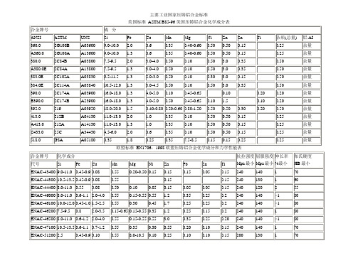
常用压铸用铝合金材料名称对照表
σ
ASTM
平均值
σ
ADC1
250
46
290
172
22
130
1.7
0.6
3.5
71.2
3.5
72
36.2
5.5
ADC3
279
48
320
179
35
170
2.7
1.0
3.5
71.4
1.8
76
36.7
2.2
ADC5
(213)
65
310
(145)
26
190
5.0
(66.4)
2.4
74
(30.1)
3.7
ADC6
0.15
0.25
余量
C433.0
S5C
A34430
4.5-6.0
2.0
0.6
0.35
0.10
0.50
0.50
0.15
0.25
余量
518.0
G8A
A05180
0.35
1.8
0.25
0.35
7.5-8.5
0.15
0.15
0.25
0.25
余量
欧盟标准EN1706:1998欧盟压铸铝合金化学成分和力学性能表
250
1
80
270
2
90
320
2
95
日本工业标准JIS H5302:2000日本压铸铝合金化学成分表
JIS牌号
ISO牌号
Cu
Si
Mg
Zn
Fe
Mn
Ni
Sn
Pb
Ti
- 1、下载文档前请自行甄别文档内容的完整性,平台不提供额外的编辑、内容补充、找答案等附加服务。
- 2、"仅部分预览"的文档,不可在线预览部分如存在完整性等问题,可反馈申请退款(可完整预览的文档不适用该条件!)。
- 3、如文档侵犯您的权益,请联系客服反馈,我们会尽快为您处理(人工客服工作时间:9:00-18:30)。
GENERAL DATA
Life Expectancy
Minimum operations Mechanical 1 x 10⁶
Electrical 1 x 10⁵at 20 A 14 VDC Res.Operate Time (max.) 4 ms max. at nominal coil voltage Release Time (max.)
1.5 ms max. at nominal coil voltage (with no coil suppression)
Dielectric Strength 500 VAC coil to contact
(at sea level for 1 min.)500 VAC between open contacts Insulation Resistance 100 megohms min. at 20°C, 500 VDC
50% RH
Dropout
Greater than 10% of nominal coil voltage Ambient Temperature
At nominal coil voltage
Operating -40°C (-40°F) to 125°C (257°F)Storage -40°C (-40°F) to 180°C (356°F)Vibration 0.062" DA at 10-55 Hz Shock
10 g
Enclosure P .B.T. polyester Terminals Tinned copper alloy Weight
21 grams
CONTACTS
Arrangement SPST (1 Form A)SPDT (1 Form C)Ratings
Resistive load:
Max. switched power:280 W Max. switched current: 20 A
Max. switched voltage: 150 VDC*
Rated load:20 A at 14 VDC (1 Form A)
20/10 A at 14 VDC (1 Form C)
* If switching voltage is greater than 30 VDC, special precautions must be taken. Please contact the factory.
Material Silver tin oxide
Resistance
< 50 milliohms initially
(6 V, 1 A voltage drop method)
20 AMP 280-ISO
AUTOMOTIVE RELAY
FEATURES
•Up to 20 Amp switching in a compact size •SPST (1 Form A), SPDT (1 Form C)•Vibration and shock resistant
•Designed for high in-rush applications (120 A)• Coil suppression available
• ISO/TS 16949, ISO9001, ISO14000 • Tested in accordance with SAE J2544
COIL
Power
At Pickup Voltage 534 mW
(typical)
Max. Continuous 3.8 W at 20°C (68°F) ambient Dissipation Temperature Rise 60°C (108°F) at nominal coil voltage Max Temperature
180°C (356°F)
NOTES
1.All values at 20°C (68°F).
2.Relay may pull in with less than “Must Operate” value.
3.Specifications subject to change without notice.
RELAY ORDERING DATA
STANDARD RELAYS
COIL SPECIFICATIONS ORDER NUMBER* Nominal Coil Must Operate Max. Continuous Coil Resistance Form A (SPST)Form C (SPDT)
VDC VDC VDC± 10%
127.220.4109AZ984–1A–12D AZ984–1C–12D *Add suffix “R” for a 680 ohm resistor in parallel with coil.
MECHANICAL DATA。
