TL66-6F-230中文资料
西安爱邦电气双钳相位表APWR13B
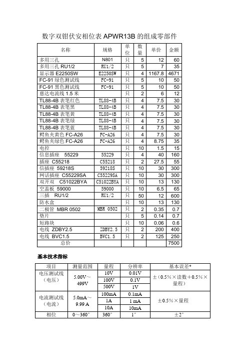
数字双钳伏安相位表APWR13B的组成零部件基本技术指标元器件组成的基本功能1 可同时测量2路电压;2 可同时测量2路钳形电流;3 测量电压间、电流间、电压与电流间的相位差;4 测量信号频率;5 双通道对称设计,相互绝缘;输入电路的安全设计,确保不会烧表组装成仪器的具体要求1 自动量程(APWR13B),无论测量电压、电流,还是测量相位,均无需人为判断量限;2 测量时可随时带电切换档位,不限制仅在测量前确定档位;3通断测试功能4 两节普通7号干电池供电,低功耗,可供持续工作50小时以上;5可准确测量低至5mA钳形小电流,适合低负荷现场和新变电站投运前的检修工作;.6 配套钳形电流互感器,钳头尖,适合在保护柜等排线密集的地方使用;7 软件校准,不需要在面板上调整电位器,支持自校准;8抗干扰能力强,在对讲机等高频信号干扰下数值跳变小,测量稳定可信;9 有数据保持功能;3.手持式,小巧便携,外带新型防震套售后服务承诺1 免费技术培训:内容包括:1.1、结构与工作原理;1.2、使用与日常保养;1.3、现场使用演示讲解;1.4、常见故障分析。
2 售后服务:2.1自交货之日起壹年内提供非用户责任的免费售后服务,更换配件费用(耗材除外),人员差旅费均由投标厂(商)承担。
2.2出现故障时,投标厂(商)可通过电话、传真等方式予以技术支持解决,若不能解决的在接到通知后72小时内赶到现场,短期不能修复,供方为用户提供一台同型号装置备用。
2.3 投标厂(商)应保证对产品的备品备件供应。
2.4 在规定的质保期内,供方应对由于设计工艺或材料的缺陷所造成的任何缺陷和故障负责。
SI2302-TP;中文规格书,Datasheet资料

Revision: A
/
3 of 5
2011/01/01
VGS, Gate to Source Voltage (V) ID, Drain Current (A)
VTH, Normalized Gate-Source Threshold Voltage
RDS(ON), Normalized RDS(ON), On-Resistance(Ohms)
IS, Source-drain current (A)
ID, Drain Current (A)
SI2302
10 25 C
Maximum Ratings @ 25OC Unless Otherwise Specified
Symbol VDS ID IDM VGS
PD R©JA
TJ
TSTG
Parameter Drain-source Voltage Drain Current-Continuous Drain Current-Pulsed a Gate-source Voltage
MCC
TM
Micro Commercial Components
5 VDS=10V ID=3.6A
4
3
2
1
0
0
2
4
6
Qg, Total Gate Charge (nC)
Figure 7. Gate Charge
VDD
RL VIN
D
VOUT
VGS
RGEN G
S
Figure 9. Switching Test Circuit
SLA6026中文资料
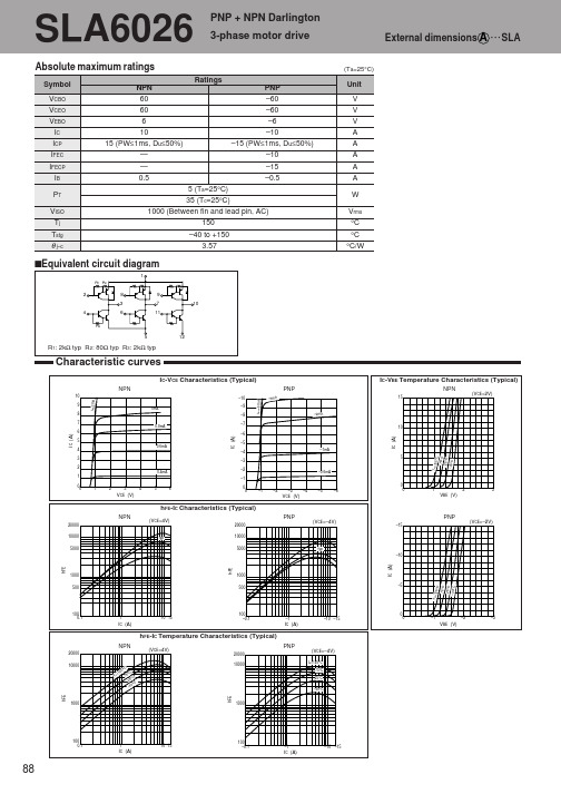
5 (Ta=25°C) 35 (Tc=25°C) 1000 (Between fin and lead pin, AC) 150 –40 to +150 3.57
sEquivalent circuit diagram
1
R1 R2
2
8 3
9 7 11 10
4
R3
6
5
12
R1: 2kΩ typ R2: 80Ω typ R3: 2kΩ typ
4.0 0.7 1.2 0.7 50 180
Characteristic curves
VCE(sat)-IB Temperature Characteristics (Typical)
NPN
3
θ j-a-PW Characteristics
PNP
(IC=–5A)
20
(IC=5A)
–3
2.5
75°C
–2.5
(Ta=25°C)
µA µA V
V V V µs µs µs µs MHz pF
µA mA V
V V V µs µs µs µs MHz pF
– – 0.6 2.0 1.5 50 100
VCC 24V, IC=6A, IB1=–IB2=12mA VCE=12V, IE=–1A VCB=10V, f=1MHz
VBE (V)
hFE-IC Characteristics (Typical)
NPN
20000 10000 5000
(VCE=4V)
20000
typ
PNP
(VCE=–4V)
PNP
–15
(VCE=–2V)
10000 5000
typ
TCS230中文资料
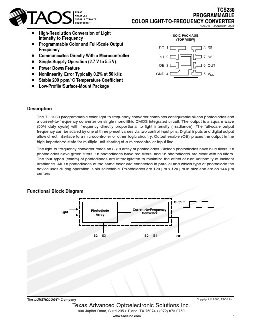
D High-Resolution Conversion of Light Intensity to FrequencyD Programmable Color and Full-Scale Output FrequencyD Communicates Directly With a Microcontroller D Single-Supply Operation (2.7 V to 5.5 V)D Power Down FeatureD Nonlinearity Error Typically 0.2% at 50 kHz D Stable 200 ppm/°C Temperature Coefficient DLow-Profile Surface-Mount PackageDescriptionThe TCS230 programmable color light-to-frequency converter combines configurable silicon photodiodes and a current-to-frequency converter on single monolithic CMOS integrated circuit. The output is a square wave (50% duty cycle) with frequency directly proportional to light intensity (irradiance). The full-scale output frequency can be scaled by one of three preset values via two control input pins. Digital inputs and digital output allow direct interface to a microcontroller or other logic circuitry. Output enable (OE) places the output in the high-impedance state for multiple-unit sharing of a microcontroller input line.The light-to-frequency converter reads an 8 x 8 array of photodiodes. Sixteen photodiodes have blue filters, 16photodiodes have green filters, 16 photodiodes have red filters, and 16 photodiodes are clear with no filters.The four types (colors) of photodiodes are interdigitated to minimize the effect of non-uniformity of incident irradiance. All 16 photodiodes of the same color are connected in parallel and which type of photodiode the device uses during operation is pin-selectable. Photodiodes are 120 µm x 120 µm in size and are on 144-µm centers.8 S37 S26 OUT 5 V DDSOIC PACKAGE (TOP VIEW)SO 1S1 2OE 3GND 4Terminal FunctionsTable 1. Selectable OptionsAvailable OptionsAbsolute Maximum Ratings over operating free-air temperature range (unless otherwise noted)†Supply voltage, V DD (see Note 1) 6 V . . . . . . . . . . . . . . . . . . . . . . . . . . . . . . . . . . . . . . . . . . . . . . . . . . . . . . . . . . . . . Input voltage range, all inputs, V I –0.3 V to V DD + 0.3 V . . . . . . . . . . . . . . . . . . . . . . . . . . . . . . . . . . . . . . . . . . . . . Operating free-air temperature range, T A 0°C to 70°C . . . . . . . . . . . . . . . . . . . . . . . . . . . . . . . . . . . . . . . . . . . . . . Storage temperature range –25°C to 85°C . . . . . . . . . . . . . . . . . . . . . . . . . . . . . . . . . . . . . . . . . . . . . . . . . . . . . . . . Lead temperature 1,6 mm (1/16 inch) from case for 10 seconds 260°C. . . . . . . . . . . . . . . . . . . . . . . . . . . . . . . †Stresses beyond those listed under “absolute maximum ratings” may cause permanent damage to the device. These are stress ratings only, and functional operation of the device at these or any other conditions beyond those indicated under “recommended operating conditions” is not implied. Exposure to absolute-maximum-rated conditions for extended periods may affect device reliability.NOTE 1:All voltage values are with respect to GND.Recommended Operating ConditionsElectrical Characteristics at T= 25°C, V = 5 V (unless otherwise noted)Operating Characteristics at V DD = 5 V, T A = 25°C, S0 = H, S1 = H (unless otherwise noted) (See Notes 3, 4, 5, 6, and 7).4.The 470 nm input irradiance is supplied by an I nGaN light-emitting diode with the following characteristics:peak wavelength λp = 470 nm, spectral halfwidth ∆λ½ = 35 nm, and luminous efficacy = 75 lm/W.5.The 524 nm input irradiance is supplied by an I nGaN light-emitting diode with the following characteristics:peak wavelength λp = 524 nm, spectral halfwidth ∆λ½ = 47 nm, and luminous efficacy = 520 lm/W.6.The 565 nm input irradiance is supplied by a GaP light-emitting diode with the following characteristics:peak wavelength λp = 565 nm, spectral halfwidth ∆λ½ = 28 nm, and luminous efficacy = 595 lm/W.7.The 635 nm input irradiance is supplied by a Al I nGaP light-emitting diode with the following characteristics:peak wavelength λp = 635 nm, spectral halfwidth ∆λ½ = 17 nm, and luminous efficacy = 150 lm/W.8.Irradiance responsivity R e is characterized over the range from zero to 5 kHz.9.Saturation irradiance = (full-scale frequency)/(irradiance responsivity).10.Illuminance responsivity Rv is calculated from the irradiance responsivity by using the LED luminous efficacy values stated in notes4, 5, and 6 and using 1 lx = 1 lm/m2.11.Nonlinearity is defined as the deviation of f O from a straight line between zero and full scale, expressed as a percent of full scale.TYPICAL CHARACTERISTICSFigure 1300500700900R e l a t i v e R e s p o n s i v i t y1100λ – Wavelength – nmPHOTODIODE SPECTRAL RESPONSIVITY0.10.20.30.40.50.60.70.80.910Figure 23005007009001100λ – Wavelength – nmPHOTODIODE SPECTRAL RESPONSIVITY WITHAPPLICATION INFORMATIONPower supply considerationsPower-supply lines must be decoupled by a 0.01-µF to 0.1-µF capacitor with short leads mounted close to the device package.Input interfaceA low-impedance electrical connection between the device OE pin and the device GND pin is required forimproved noise immunity.Output interfaceThe output of the device is designed to drive a standard TTL or CMOS logic input over short distances. If lines greater than 12 inches are used on the output, a buffer or line driver is recommended.Photodiode type (color) selectionThe type of photodiode (blue, green, red, or clear) used by the device is controlled by two logic inputs, S2 and S3 (see Table 1).Output frequency scalingOutput-frequency scaling is controlled by two logic inputs, S0 and S1. The internal light-to-frequency converter generates a fixed-pulsewidth pulse train. Scaling is accomplished by internally connecting the pulse-train output of the converter to a series of frequency dividers. Divided outputs are 50%-duty cycle square waves with relative frequency values of 100%, 20%, and 2%. Because division of the output frequency is accomplished by counting pulses of the principal internal frequency, the final-output period represents an average of the multiple periods of the principle frequency.The output-scaling counter registers are cleared upon the next pulse of the principal frequency after any transition of the S0, S1, S2, S3, and OE lines. The output goes high upon the next subsequent pulse of the principal frequency, beginning a new valid period. This minimizes the time delay between a change on the input lines and the resulting new output period. The response time to an input programming change or to an irradiance step change is one period of new frequency plus 1 µS. The scaled output changes both the full–scale frequency and the dark frequency by the selected scale factor.The frequency-scaling function allows the output range to be optimized for a variety of measurement techniques. The scaled-down outputs may be used where only a slower frequency counter is available, such as low-cost microcontroller, or where period measurement techniques are used.Measuring the frequencyThe choice of interface and measurement technique depends on the desired resolution and data acquisition rate. For maximum data-acquisition rate, period-measurement techniques are used.Output data can be collected at a rate of twice the output frequency or one data point every microsecond for full-scale output. Period measurement requires the use of a fast reference clock with available resolution directly related to reference clock rate. Output scaling can be used to increase the resolution for a given clock rate or to maximize resolution as the light input changes. Period measurement is used to measure rapidly varying light levels or to make a very fast measurement of a constant light source.Maximum resolution and accuracy may be obtained using frequency-measurement, pulse-accumulation, or integration techniques. Frequency measurements provide the added benefit of averaging out random- or high-frequency variations (jitter) resulting from noise in the light signal. Resolution is limited mainly by available counter registers and allowable measurement time. Frequency measurement is well suited for slowly varying or constant light levels and for reading average light levels over short periods of time. Integration (the accumulation of pulses over a very long period of time) can be used to measure exposure, the amount of light present in an area over a given time period.MECHANICAL INFORMATIONPACKAGE DPLASTIC SMALL-OUTLINE PACKAGEDETAIL AA2y 6y 1.8 +NOTES: A.All linear dimensions are in millimeters.B.Package is molded with an electrically nonconductive clear plastic compound having an index of refraction of 1.55.C.Actual product will vary within the mechanical tolerances shown on this specification. Designs for use of this product MUST allowfor the data sheet tolerances.D.Pin 4 (GND) is mechanically connected to the die mount pad.E.The 8 × 8 photodiode array area is 1.15 mm × 1.15 mm (1.33 sq. mm).F.This drawing is subject to change without notice.Figure 3. TCS230 Mechanical SpecificationsPRODUCTION DATA — information in this document is current at publication date. Products conform to specifications in accordance with the terms of Texas Advanced Optoelectronic Solutions, Inc. standard warranty. Production processing does not necessarily include testing of all parameters.NOTICETexas Advanced Optoelectronic Solutions, Inc. (TAOS) reserves the right to make changes to the products contained in this document to improve performance or for any other purpose, or to discontinue them without notice. Customers are advised to contact TAOS to obtain the latest product information before placing orders or designing TAOS products into systems. TAOS assumes no responsibility for the use of any products or circuits described in this document or customer product design, conveys no license, either expressed or implied, under any patent or other right, and makes no representation that the circuits are free of patent infringement. TAOS further makes no claim as to the suitability of its products for any particular purpose, nor does TAOS assume any liability arising out of the use of any product or circuit, and specifically disclaims any and all liability, including without limitation consequential or incidental damages.TEXAS ADVANCED OPTOELECTRONIC SOLUTIONS, INC. PRODUCTS ARE NOT DESIGNED OR INTENDED FOR USE IN CRITICAL APPLICATIONS IN WHICH THE FAILURE OR MALFUNCTION OF THE TAOS PRODUCT MAY RESULT IN PERSONAL INJURY OR DEATH. USE OF TAOS PRODUCTS IN LIFE SUPPORT SYSTEMS IS EXPRESSLY UNAUTHORIZED AND ANY SUCH USE BY A CUSTOMER IS COMPLETELY AT THE CUSTOMER’S RISK.LUMENOLOGY is a registered trademark, and TAOS, the TAOS logo, and Texas Advanced Optoelectronic Solutions are trademarks of Texas Advanced Optoelectronic Solutions Incorporated.。
力姆泰克-电动推杆

力 姆 泰 克®2012Perfect Linear Motion欧洲先进设计和东方智慧的融合,引领机械直线运动的全新发展方向。
电动推杆的丰富系列组合:推力从10公斤到50吨;驱动可以选择直流电机,交流电机,步进电机,伺服电机;丝杠可以是普通梯形齿,到滚珠丝杠,至行星滚柱丝杠任意选择;各式的防护附件,过载附件,闭环控制附件,安装附件等使电动推杆的系列可以满足客户的各式直线运动的要求。
螺旋升降机的专利外形设计,独特的方形壳体凹槽,加大外壳散热能力,提高润滑脂等产品综合寿命。
球墨铸铁的外壳材料选择,大幅提高壳体强度和性能,以及高温和恶劣环境下的应用。
方形尾罩设计,可控制丝杠的不自转功能。
安全螺母是设备安全的保障,及时监控丝杠螺母的磨损程度。
先进的加工设备和加工组装工艺,是高质量零部件的保证,先进的设计理念创造了抗冲击能力强,高强度,低噪音,长寿命,体积小的优质产品。
模块化组合丰富了产品的应用范围,推杆和电机/减速电机/特殊功能附件等的任意组合,为客户提供上千种不同的轻而易举选择。
目录LAM系列Fu%=(t2+t4+t6) / 10分钟Fu%=10分钟内工作时间百分比t2,t4,t6:工作时间t1,t3,t5:等待时间工作制计算过程分钟时间位移 st1 t2 t3 t4 t5 t6F1F2F3F4S1 S2 S3 S4行程 mm 负载随行程的变化曲线图电动推杆型号标注系列型号 基座号 减速比 标准行 m m L A P 系列22 H 1 50 L B P 系列25 H 2 100 28 V 1 200 32 V 2 30035N 1 400 40 N 2 500 56 L 1 600 63 L 2 700 80 X L 1 800 特殊系列型号 基座号减速比标准行m m L A M 系列1S 0 50 2 S 1 100 L B M 系列 3 S 2 150 4 S 3 200 5 S 4 250 6 300 7特殊 89注:电机的防护等级标准为I P 55(电机于300毫米时稳定性问题请与当地工程师确认。
ALTIVAR 66 调速电子变压器用户手册说明书

Bulletin No. 30072-450-73May 2002Raleigh, NC, USAALTIVAR ® 66Addendum to VD0C06S304E ATV66 Repair PartsAddendumRetain for future use.This Addendum replaces Appendix A of instruction bulletin VD0C06S304E, ALTIVAR 66® Adjustable Speed Drive Controllers for Asynchronous Motors User’s Manual, Constant and Variable T orque: 1 to 400 hp, 460 V and 1 to 50 hp, 230 V , Receiving, Installation, and Start-up . This addendum contains revised repair parts information.Replacement of repair parts requires the use of special tools and installation procedures not included with the repair parts kits. Before replacing any repair part, consult the ALTIVAR 66 Drive Controller Service and Troubleshooting Manual , bulletin number VD0C06S701 (1–75 hp, 100 hp VT) orVD0C06S702 (100–350 hp, 125–400 hp VT). These manuals can beordered from your local Square D distributor. Repair parts must be replaced only by qualified electrical personnel familiar with the service and troubleshooting manual.When ordering repair parts for the A TV66C10N4 to A TV66C19N4 drive controllers, check the drive controller serial number and follow theseguidelines. Refer to pages 3–5 of bulletin VD0C06S304E for assistance in finding the drive controller serial number.•If the serial number has a “1” as the seventh digit, select repair parts from the repair parts list beginning on page 2 of this addendum. All drivecontrollers shipped on or after June 1, 1998 have a “1” as the seventh digit of the serial number. See Figure 2 on page 2 for illustrations of these controllers. •If the serial number does not have a “1” as the seventh digit, consult bulletin VD0C06S702 for repair parts. These are drive controllers that shipped on or before May 31, 1998. They are illustrated in Figure e the repair parts list beginning on page 2 of this addendum for all other drive controller models (A TV66U41N4 to A TV66D79N4, A TV66U41M2 to A TV66D46M2, and A TV66C23N4 to A TV66C31N4).Figure 1:ATV66C10N4–C19N4: Shipped On or Before May 31, 1998INTRODUCTIONSELECTING REPAIR PARTS FOR ATV66C10N4 TO ATV66C19N4 DRIVECONTROLLERSFor controllers like this, select repair parts from bulletin VD0C06S702, Service and Troubleshooting Manual (100–350 hp, 125–400 hp VT).Addendum to VD0C06S304E Bulletin No. 30072-450-73ATV66 Repair Parts May 2002Figure 2:ATV66C10N4–C19N4: Shipped On or After June 1, 1998For controllers like these, select repair parts from the following Repair Parts List.Repair Parts ListDescriptionDrive Controller Part No.NoteALTIVAR 66 Adjustable Speed Drive Controllers Service and Troubleshooting ManualATV66 1–75 hp,100 hp VT VD0C06S701ATV66 100 hp CT, 125–400 hpVD0C06S702Control Kit — 460 VATV66U41N4 to D79N4ATV66C10N4 to C31N4VX4A66CK1VX4A66CK2Matched keypad display and control basket with latest firmwareControl Kit — 208/230 VATV66U41M2 to D46M2 (except ATV66D23M2S264U)VX4A66CK1 ATV66D23M2S264UVX4A66CK1S260Keypad DisplayRefer to the section “Identifying the FirmwareVersion” in Chapter 4 of bulletin VD0C06S304E and determine the firmware version of your drive controller.For drive controllers with firmware level 3.0 andlaterATV66 all sizesVW3A66206UFor drive controllers with firmware version earlier than 3.0Order the control kit listed above that is appropriate for your drive controller.Removable Control Terminal StripsATV66 all sizesVZ3N006J1, J12, and J13 on control basketBulletin No. 30072-450-73Addendum to VD0C06S304EMay 2002ATV66 Repair PartsPower Board — 460 VATV66U41N4VX5A66U41N4Includes IGBT block, rectifier diode, heatsink, and fan ATV66U54N4VX5A66U54N4ATV66U72N4VX5A66U72N4ATV66U90N4VX5A66U90N4ATV66D12N4VX5A66D12N4ATV66D16N4VX5A66D16N4Power board onlyATV66D23N4VX5A66D23N4ATV66D33N4VX5A66D33N4ATV66D46N4VX5A66D46N4ATV66D54N4VX5A66D54N4ATV66D64N4VX5A66D64N4ATV66D79N4VX5A66D79N4ATV66C10N4 VX5A661C10N4ATV66C13N4VX5A661C13N4ATV66C15N4VX5A661C15N4ATV66C19N4 VX5A661C19N4ATV66C23N4VX5A661C23N4ATV66C28N4VX5A661C28N4ATV66C31N4VX5A661C31N4Power Board — 208/230 VATV66U41M2VX5A662U41M2Includes IGBT block and rectifier diode ATV66U72M2VX5A662U72M2ATV66U90M2VX5A662U90M2ATV66D12M2VX5A66D12M2Power board onlyATV66D16M2VX5A66D16M2Power Board and Gate Driver Board — 208/230 VATV66D23M2VX5A66D234M2Matched set ATV66D33M2VX5A66D335M2ATV66D46M2VX5A66D466M2Gate Driver Board — 460 VATV66D16N4VX5A66103Gate driver board only ATV66D23N4VX5A66104ATV66D33N4VX5A66105ATV66D46N4VX5A66106ATV66D54N4VX5A66107ATV66D64N4VX5A66108ATV66D79N4VX5A66109Gate Driver Board — 208/230 V ATV66D12M2VX5A66112ATV66D16M2VX5A66113Inverter IGBT — 460 V[1] For units with a serial number starting with “6W”, or for units with a serial number starting with “86” and a date code of 0216 or earlier. [2]For units with a serial number starting with “86”and a date code of 0217 or later.Refer to pages 3–5 of bulletin VD0C06S304E for assistance in finding the serial number and date code.ATV66D16N4VZ3lM2050M1201 1 dual IGBT block ATV66D23N4VZ3lM2075M1201ATV66D33N4VZ3lM2100M1201ATV66D46N4, D54N4VZ3lM2150M1201ATV66D64N4VZ3lM2200M1201ATV66D79N4 [1]VZ3IM2300M1201ATV66D79N4 [2]VZ3IM2200M1202ATV66C10N4VZ3IM2300M1202 2 IGBT blocks, 2 snubber boards, 2 gate driver boards, 1 clamp moduleATV66C13N4 to C19N4VZ3IM2400M1202ATV66C23N4, C28N4VZ3IM1400M1207 4 IGBT blocks, 2 snubber boards, 2 gate driver boards ATV66C31N4VZ3IM1500M1207Repair Parts List (Continued)DescriptionDrive Controller Part No.NoteAddendum to VD0C06S304E Bulletin No. 30072-450-73ATV66 Repair Parts May 2002Inverter IGBT — 208/230 VATV66D12M2VZ3IM2075M0601 1 dual IGBT blockATV66D16M2VZ3IM2100M0601ATV66D23M2VZ3IM2150M0601ATV66D33M2VZ3IM2200M0601ATV66D46M2VZ3IM2300M0601Inverter IGBT Clamp Capacitor ATV66C23N4 to C31N4VY1ADC610 1 capacitorDynamic Braking IGBT — 460 VATV66D16N4, D23N4VZ3IM1025M1001 1 IGBT BlockATV66D33N4, D46N4VZ3IM2050M1201ATV66D54N4VZ3IM2100M1201ATV66D64N4, D79N4VZ3IM2150M1201ATV66C10N4 to C19N4VZ3IM1300M1202 1 IGBT block, 1 diode block,1 snubber board, 1 gate driver board ATV66C23N4VZ3IM1400M1208ATV66C28N4, C31N4VZ3IM1300M1208 2 IGBT blocks, 2 diode blocks,2 snubber boards, 1 gate driver boardDynamic Braking IGBT — 208/230 VATV66D12M2, D16M2VZ3IM1060M0601 1 IGBT blockATV66D23M2VZ3IM2075M0601ATV66D33M2VZ3IM2100M0601ATV66D46M2VZ3IM2150M0601Dynamic Braking Clamp Capacitor ATV66C10N4 to C19N4VY1ADC616 1 capacitorATV66C23N4 to C31N4VY1ADC614Line Filter Board — 460 VATV66D16N4, D23N4VX4A66103Board onlyATV66D33N4, D46N4VX4A66104ATV66D54N4 to D79N4VX4A66105ATV66C10N4 to C31N4VX4A66106Assembly with board and capacitors Line Filter Board — 208/230 VATV66D12M2, D16M2VX4A66103Board onlyATV66D23M2, D33M2VX4A66104ATV66D46M2VX4A66105Line Rectifier Diode — 460 VATV66D16N4, D23N4VZ3DM6075M16016-pack diode block ATV66D33N4VZ3DM2080M1606 1 dual diode block ATV66D46N4VZ3DM2100M1601ATV66D54N4 to D79N4VZ3DM2160M1606ATV66C10N4, C13N4VZ3DM2170M1602ATV66C15N4VZ3DM2260M1602ATV66C19N4VZ3DM2350M1602ATV66C23N4 to C31N4VZ3DM2600M1602Line Rectifier Diode — 208/230 VATV66D12M2, D16M2VZ3DM6075M16016-pack diode block ATV66D23M2VZ3DM2080M16061 dual diode block ATV66D33M2VZ3DM2100M1601ATV66D46M2VZ3DM2160M1606DC Bus Capacitor—460 VATV66D16N4, D23N4VY1ADC152V450 1 capacitorATV66D33N4, D46N4VY1ADC472V450ATV66D54N4VY1ADC605Assembly with capacitors and stirring fan ATV66D64N4, D79N4VY1ADC606ATV66C10N4 to C19N4VY1ADC615Assembly with capacitors ATV66C23N4 to C31N4VY1ADC608DC Bus Capacitor—208/230 VATV66D12M2, D16M2VY1ADC152V450 1 capacitorATV66D23M2, D33M2VY1ADC472V450ATV66D46M2VY1ADC605Assembly with capacitors and stirring fanRepair Parts List (Continued)DescriptionDrive Controller Part No.NoteBulletin No. 30072-450-73Addendum to VD0C06S304EMay 2002ATV66 Repair PartsDC Bus Capacitor Bank Plexiglass Shield ATV66C10N4 to C19N4VY1ADV611Shield with mounting screws Discharge Resistor — 460 VATV66D33N4 to D79N4VZ3R5K0W040 1 resistor ATV66C10N4 to C19N4VZ3R2K5W600 2 resistorsATV66C23N4 to C31N4VZ3R1K2W480 1 resistorDischarge Resistor — 208/230 V ATV66D23M2 to D46M2VZ3R5K0W040Precharge Resistor — 460 VATV66D16N4, D23N4VZ3R033W009ATV66D33N4, D46N4VZ3R010W025ATV66D54N4 to D79N4VZ3R010W481ATV66C10N4 to C31N4VZ3R010W270 2 resistors Precharge Resistor — 208/230 VATV66D12M2, D16M2VZ3R033J710 1 resistorATV66D23M2, D33M2VZ3R010W025ATV66D46M2VZ3R010W481Precharge Contactor — 460 VATV66D16N4, D23N4LP4D1801BW3 1 contactorATV66D33N4LC1D1801P7ATV66D46N4LC1D2501P7ATV66D54N4, D64N4LC1D4011P7ATV66D79N4LC1D6511P7ATV66C10N4, C13N4VY1A661C1010ATV66C15N4, C19N4VY1A661C1510ATV66C23N4 to C31N4VY1A661C2310Precharge Contactor — 208/230 VATV66D12M2, D16M2LP4D2500BW3ATV66D23M2LC1D3201P7ATV66D33M2LC1D5011P7ATV66D46M2LC1D4011P7Precharge Contactor Auxiliary Contact Block ATV66C10N4 to C31N4LA1DN04 1 contact blockPrecharge Circuit Protector ATV66C10N4 to C31N4GV2M10Heatsink Fan — 460 VATV66U41N4, U54N4VZ3V661Fan(s) and mounting bracketATV66U72N4VZ3V662ATV66U90N4, D12N4VZ3V663ATV66D16N4, D23N4VZ3V664ATV66D33N4 to D79N4VZ3V665 1 fanATV66C10N4 to C19N4VZ3V670Fan assembly and capacitor ATV66C23N4 to C31N4VZ3V666 1 fan and capacitorHeatsink Fan — 208/230 VATV66U41M2VZ3V662Fan(s) and mounting bracket ATV66U72M2, U90M2VZ3V663ATV66D12M2, D16M2VZ3V664ATV66D23M2 to D46M2VZ3V665 1 fanStirring Fan — 460 VATV66D33N4 to D79N4VZ3V6654Power board fan ATV66D54N4 to D79N4VZ3V6655Capacitor bank fan ATV66C10N4 to C19N4VZ3V671Power board fan ATV66C23N4 to C31N4VZ3V669IGBT fan Stirring Fan — 208/230 V ATV66D23M2 to D46M2VZ3V6654Power board fan ATV66D46M2VZ3V6655Capacitor bank fanFan Failure Detection Assembly ATV66C23N4 to C31N4VY1ADR100Resistor and temperature switch Fan Failure Relay AssemblyATV66C23N4 to C31N4VZ3SA66012Relay and retaining clip Power Supply for Overtemperature Detection CircuitATV66C23N4 to C31N4VY1A66200Power supply only Heatsink T emperature SensorATV66C10N4 to C31N4VZ3GN005NTC thermistor and cableRepair Parts List (Continued)DescriptionDrive Controller Part No.NoteAddendum to VD0C06S304E Bulletin No. 30072-450-73ATV66 Repair Parts May 2002T emperature SwitchATV66C10N4 to C19N4VZ3G007 1 switch—mounted on fuse bar ATV66C10N4 to C19N4VZ3G008 2 switches—mounted on heatsink and motor current sensorATV66C23N4 to C31N4VZ3G004 1 68 °C switch and 1 85 °C switch, heatsink mounted Motor Current Sensor — 460 VATV66D33N4, D46N4VY1A66104 2 sensorsATV66D54N4 to D79N4VY1A66105ATV66C10N4, C13N4VY1A66106 1 sensor ATV66C15N4, C19N4VY1A66107ATV66C23N4 to C31N4VY1A66108Motor Current Sensor — 208/230 VATV66D23M2VY1A66104 2 sensors ATV66D33M2, D46M2VY1A66105Ground Fault Sensor—460 V ATV66C10N4 to C19N4VY1A66109 1 sensor ATV66C23N4 to C31N4VY1A66110Control Power Transformer — 460 VATV66D33N4 to D79N4VY1ADA604T ransformer only ATV66C10N4 to C19N4VY1ADA606ATV66C23N4 to C31N4VY1ADA607Control Power Transformer — 230 V ATV66D23M2 to D46M2VY1ADA614Control Power Fuses ATV66C10N4 to C31N4DF3CF00501 2 fuses, F5 and F6DC Bus FuseATV66C10N4, C13N4VY1ADF250V700 1 fuseATV66C15N4, C19N4VY1ADF350V700ATV66C23N4 to C31N4VY1ADF400V700AC Line FuseATV66C23N4VY1ALF700V700ATV66C28N4VY1ALF800V700ATV66C31N4VY1ALF900V700Power T erminal Blocks — 460 VATV66D16N4, D23N4VZ3N603All output terminals and DIN rail for mounting ATV66D33N4, D46N4VZ3N604ATV66D54N4 to D79N4VZ3N605Power T erminal Blocks — 208/230 VATV66D12M2, D16M2VZ3N603ATV66D23M2, D33M2VZ3N604ATV66D46M2VZ3N605Box Lug Power T erminalATV66C10N4 to C19N4VZ3N008Three terminals for replacing power or ground terminalsA TV66C10N4–C13N4: L1, L2, L3, T1, T2, T3, +, –, GNDA TV66C15N4–C19N4: T1, T2, T3, +, –, GNDClam Shell Power T erminal ATV66C15N4 to C19N4VZ3N009Three terminals for replacing power terminals L1, L2, L3Power T erminal Plexiglass Shield ATV66C10N4 to C19N4VY1ADV612Dynamic Braking Flexible Bus ATV66C23N4 to C31N4VZ3N626Connects capacitor bank to PA terminal and DB IGBT moduleFlex Cables — 460 V(Control Board J3, J4, and J5)ATV66U41N4 to D12N4VZ3N601 3 flat ribbon cablesATV66D16N4, D23N4VZ3N613ATV66D33N4 to D79N4VZ3N615ATV66C10N4 to C31N4VZ3N616Flex Cables — 208/230 V (Control Board J3, J4, and J5)ATV66U41M2 to U90M2VZ3N601ATV66D12M2, D16M2VZ3N613ATV66D23M2 to D46M2VZ3N615Repair Parts List (Continued)Description Drive Controller Part No.NoteBulletin No. 30072-450-73Addendum to VD0C06S304EMay 2002ATV66 Repair PartsInternal Hardware Kit — 460 VATV66U41N4 to U72N4VY1ADV601Specialty hardware, mounting posts, etc.ATV66U90N4, D12N4VY1ADV602ATV66D16N4, D23N4VY1ADV603ATV66D33N4, D46N4VY1ADV604ATV66D54N4 to D79N4VY1ADV605ATV66C10N4 to C19N4VY1ADV613ATV66C23N4 to C31N4VY1ADV614Internal Hardware Kit — 230 VATV66U41M2VY1ADV601ATV66U72M2, U90M2VY1ADV602ATV66D12M2, D16M2VY1ADV603ATV66D23M2, D33M2VY1ADV604ATV66D46M2VY1ADV605Packaging Kits — 208/230/460 V(Order this kit if the control basket is not mounted to a white metallic ground plane within the drivecontroller)ATV66U41N4 to U72N4VY1A66101All plastic sides, covers, and front door ATV66U90N4, D12N4VY1A66102ATV66D16N4, D23N4VY1A66103ATV66U41M2VY1A66101ATV66U72M2, U90M2VY1A66102ATV66D12M2, D16M2VY1A66103Packaging Kits — 208/230/460 V(Order this kit if the control basket is mounted to a white metallic ground plane within the drivecontroller)ATV66U41N4 to U72N4VY1A66111ATV66U90N4, D12N4VY1A66112ATV66D16N4, D23N4VY1A66113ATV66U41M2VY1A66111ATV66U72M2, U90M2VY1A66112ATV66D12M2, D16M2VY1A66113Clip Pliers(T ool for removing voltage regulator heatsink clips)ATV66U41N4 to D23N4VY1ADV608Use when replacing power board, all IGBTs, filter board, precharge components, bus capacitors, and line rectifier diodes.ATV66U41M2 to D16M2Repair Parts List (Continued)DescriptionDrive Controller Part No.NoteElectrical equipment should be serviced only by qualified personnel. No responsibility is assumed by Schneider Electric for any consequences arising out of the use of this material. This document is not intended as an instruction manual for untrained persons.ALTIVAR ® 66 Addendum to VD0C06S304E ATV66 Repair Parts Bulletin No. 30072-450-73Instruction Bulletin May 2002Square D Company 8001 Hwy 64 East Knightdale, NC 275451-888-SquareD (1-888-778-2733)。
HT66FXX中文版详细资料
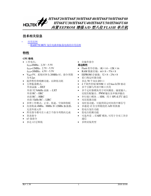
H T66F30 1 6 D IP -A /N S O P -A /S S O P -A
P A 0 /C 0 X /T P 0 _ 0 /A N 0 1 VSS&AVSS 2 P B 4 /X T 2 3 P B 3 /X T 1 4 P B 2 /O S C 2 5 P B 1 /O S C 1 6 VDD&AVDD 7 P B 0 /R E S 8
型号
外部 VDD ROM RAM EEPROM I/O 中断 A/D
TM 模块
接口 (SPI/I2C)
UART
堆栈
封装形式
HT66F20*
2.2V~ 5.5V
1K×14
64×8
32×8
18
2
12-bit×8
10-bit CTM×1 10-bit STM×1
√
√4
16DIP/NSOP/SSOP 20DIP/SOP/SSOP
在模拟特性方面,这款单片机包含一个多通道 12 位 A/D 转换器和双比较器功能。还带有多个 使用灵活的定时器模块,可提供定时功能、脉冲产生功能及 PWM 产生功能。内建完整的 SPI 和 I2C 功能,为设计者提供了一个易与外部硬件通信的接口。内部看门狗定时器、低电压复位和低电压检 测等内部保护特性,外加优秀的抗干扰和 ESD 保护性能,确保单片机在恶劣的电磁干扰环境下可靠 地运行。
fSYS=8MHz:2.2V~5.5V fSYS=12MHz:2.7V~5.5V fSYS=20MHz:4.5V~5.5V • VDD=5V,系统时钟为 20MHz 时,指令周期 为 0.2µs • 提供暂停和唤醒功能,以降低功耗 • 五种振荡模式: 外部晶振 -- HXT 外部 32.768kHz 晶振 -- LXT 外部 RC -- ERC 内部 RC -- HIRC 内部 32kHz RC -- LIRC • 多种工作模式:正常、低速、空闲和休眠 • 内部集成 4MHz,8MHz 和 12MHz 振荡器, 无需外接元件 • 所有指令都可在 1 或 2 个指令周期内完成 • 查表指令 • 63 条指令 • 多达 12 层堆栈
AXHV0002中文资料
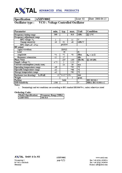
Specification AXHV0002Issue: 02 Date: 2008-04-15 Oscillator type : VCO – Voltage Controlled OscillatorParametermin. typ. max. Unit ConditionFrequency tuning range360 610 MHz @ 25°C Frequency adjustment rangeEFC voltage V C 1 11 V Tuning sensitivity 10 32 40 MHz/VEFC slope (∆f / ∆V C )positive RF outputSignal waveform SINUSLoad 50 ΩAmplitude +4 +5 +8 dBm R L = 50 Ω Harmonics attenuation 12 17 dBcPhase Noise-107 -103 dBc/Hz @ 100 kHz Supply voltage V S 4.75 5 5.25 V Current consumption (steady state) 24 26 mAOperating temperature range-40 +85 °C Operable temperature range-45 +90 °C Storage temperature range-45 +95 °C Enclosure (see drawing) LxWxH12.7 x 12.7 x 6.1 mm Weight5 gram Packingbulk IEC 60286-3 ESD Sensitivity1500 V HBM, IEC 61000-4-2 Notes:1. Terminology and test conditions are according to IEC standard IEC60679-1, unless otherwise statedOrdering Code:Model (Specification) Frequency Range [MHz] AXHV0002 360-610Enclosure drawingPin connectionsPin # Symbol Function P1 V C Control Voltage (EFC) P2 RF OUT RF Output P3 V S Supply Voltage P4 N.C. Not Connected All othersGND Ground Note:Drawing may not show appearance in detailEnvironmental conditionsTest IEC 60068 Part ... IEC 60679-1clause ...Test conditionsVisual inspection, dimensions 4.3 Enclosure styles as in IEC 60679-3 or 61837, if applicable Sealing tests (if applicable) 2-17 4.6.2 Gross leak: Test Qc, Fine leak: Test QkSolderability Resistance to soldering heat 2-20 2-58 4.6.3 Test Ta (235 ± 5)°C Method 1 Test Tb Method 1A, 5sShock* 2-27 4.6.8 Test Ea, 3 x per axes 100g, 6 ms half-sine pulseBump* 2-29 4.6.6 Test Eb, 4000 bumps per Axes, 40g, 6 msFree fall*2-324.6.9 Test Ed procedure 1, 2 drops from 1m height Vibration, sinusoidal* 2-6 4.6.7 Test Fc, 30 min per axes,10 Hz - 55 Hz 0,75mm; 55 Hz - 2 kHz, 10gRapid change of temperature 2-14 4.6.5 Test Na, 10 cycles at extremes of operating temperature rangeDry heat2-2 4.6.14 Test Ba, 16 h at upper temperature indicated by climatic category Damp heat, cyclic* 2-30 4.6.15 Test Db variant 1 severity b), 55°C/95% r.H., 6 cyclesCold2-1 4.6.16 Test Aa, 2 h at lower temperature indicated by climatic category Climatic sequence* 1-7 4.6.17 Sequence of 4.6.14, 4.6.15 (1st cycle), 4.6.16, 4.6.15 (5 cycles) Damp heat, steady state*2-3 4.6.18 Test Ca, 56 daysEndurance tests - ageing- extended aging4.7.1 4.7.230 days @ 85°C, OCXO @25°C 1000h, 2000h, 8000h @85°C。
TL226-2006(中文大纲)

标准中心关键词:油漆,喷漆,内饰件,电压印,热压印,避免有害物质按VW 911 01对于一次完整的实验,至少需要5件成品件或总面积为0.5 m2的零件。
成品件的性能以及要求的技术参数,在喷漆时要求将损伤控制在允许范围内。
涂层/喷漆,也许还有补漆,必须牢牢的黏附在基材或首次喷漆的漆层上。
补漆必须给予标明。
对于所有要检验的零件,供应商提供下面的信息:1. 基体材料的信息(制造厂商名称和VDA-标记)2. 颜色代码3. 前处理 a) 清洗,例如使用异丙醇 b) 表面活化,例如火焰处理 c) 其他表面处理,例如锌磷化4. 油漆结构(所有参数的定义) 例如双组分-软漆,也就是手感漆。
底漆XYZ,厂商XYZ,填料 XYZ 色漆XYZ,厂商XYZ,填料 XYZ MV(混合比):10:x,混合比必须符合(组系-)油漆的认可。
所使用的固化剂XYZ,厂商XYZ,填料XYZ 喷漆方,喷漆方的奥迪特评审证明5.喷漆设备6.喷漆地点7.喷漆时间3.2外观和手感零件在整个表面要有均匀的外观,同时认可试样的手感、光泽、颜色要与图纸要求相一致。
缩孔、裂纹、漆流挂以及其他明文规定的外观损伤都是不允许的。
有关色调和光泽度的文献见VW 501 90的首件试验报告。
3.3曝晒试验曝晒试验按VW 501 85试验过程中的抱怨由供应商来负责,这样有利于抱怨的消除和油漆系统的改善。
3.4喷漆过程喷漆过程必须由油漆使用方和油漆生产方协商确定。
双方共同参与首件认可报告,也就是说,双方要共同承担满足前述技术要求的责任。
现分述如下:— 油漆生产商要及时通报TL标准的遵循情况,提供加工细则和使用方面的技术支持。
— 油漆使用方要及时通报基材信息(塑料类型和供应商名称),尽可能早的按技术要求进行检验(还有对于预批量的零件:至少要检验他们的附着力),要接受并遵守油漆生产商提供的加工细则,并要求提供油漆使用技术支持。
3.5预处理所有提供的实验样件都要进行预处理:3.8 耐划伤试验按 PV 3952条件,存放240h。
电主轴62-60说明书
YG62-60L 使用说明书目录一、产品概述 (1)▷产品简介 (1)▷产品用途 (1)二、主轴外形图 (2)三、技术参数表 (3)四、电机特性曲线 (4)五、主轴安装说明 (5)▷测温传感器及其阻温特性对照表 (6)▷循环冷却系统说明 (8)▷换刀装置的控制 (8)▷空气密封及主轴吹尘的控制 (8)▷压缩空气气体质量要求 (9)▷跑合程序说明 (9)▷主轴驱动要求 (9)▷主轴安装要求 (10)六、使用注意事项 (11)▷主轴装机过程注意事项 (11)▷启动注意事项 (11)▷维护和保养注意事项 (12)一、产品概述▷产品简介1.本主轴为电机内装式主轴,内置三相交流异步感应电机,有变频器进行无级变速控制。
由于本主轴具有结构紧凑、重量轻、惯性小、振动小、噪声低等特点所以可以实现高转速,高精度及高运转稳定性。
2.本主轴轴承采用油脂润滑陶瓷复合球轴承,可在轴承的使用寿命周期内实现终生润滑3.本主轴使用强制冷却的方式对电机、前后轴承进行冷却。
冷却液流经主轴机体合理布置的循环水道带走主轴高速旋转产生的热量,达到热平衡,使电主轴的温度恒定在一定值内。
外置的冷却装置:保持冷却液的温度恒定。
4.本主轴内置PTC130测温传感器(其技术参数详见本说明书其它章节),如需进行对电机做温度保护时可以读取。
5.刀具加紧方式:本主轴内置自动换刀装置,刀柄形式为直接换刀,标配为ф6,可选配ф4,ф3.175.▷产品用途本产品为基础主轴,主要用于雕铣机或加工中心进行有色金属、黑色金属、玻璃、石墨等材料的加工。
二、主轴外形图三、技术参数表四、电机特性曲线▷功率、扭矩-转速曲线▷电压-频率曲线五、主轴安装说明▷测温传感器技术参数1.传感器类型:PTC(正温度系数),常温阻值R25≤255Ω2.开关特性:温控点Tk=130℃,Tk-5≤1650Ω,Tk+5≧4200Ω偏差△T=±5℃, Tk重复性△T=±0.5℃4.热动作时间:≤2S5.最大工作电压30V(DC),绝缘强度2.5KW6.最高允许存放温度180℃,最低允许存放温度-25℃▷循环冷却系统说明◆水冷要求:推荐使用蒸馏水,同时推荐使用费诺克斯(Femox)保护剂F1(使用配比1:200).冷却液的温度建议为24℃-28℃,当不能达到时,应该与环境温度基本一致,进水管、回水管温差不超过5℃◆通常在冷却系统的回水管中设置流量开关,以便控制冷却液的流量,确保主轴冷却液的正常供给。
耐候性扎线带

带
• Available in seven loop tensile strengths from 8 lbs. (36N).8KG up to 250 lbs. (1112N).114KG
特
to provide an economical selection
点
每英寸更多的齿 More Teeth Per In ch
• Reduces operator fatigue • Thin tapered tip facilitates threading, easier
initial insertion
. 数量较多的锁齿设计,提供更高的拉伸强度
和可靠性
. 自锁式和可退式扎带两种不同的设计应用于
不同场合的需求
• Multiple locking tooth design provides greater strength and reliability
G80MB G90MB G100MB G120MB G140MB G150MB G160MB G200MB G250MB G300MB G120IB G140IB G150IB G180IB G200IB G215IB G250IB G300IB G370IB G120STB G150STB G160STB G190STB G200STB G215STB G250STB G280STB G300STB G370STB G390STB G430STB G450STB G530STB G550STB G635STB G685STB G730STB G830STB G920STB
*Available in a wide range of materials.
*Internal serrations allowing for a positive hold onto cable and pipe bundles.
UL62中文版
UL 62-2001软线和装置线FLEXIBLE CORD AND FIXTURE WIRE上海电缆研究所信息中心译前言A.本标准包含美国保险商实验所(UL)产品追踪服务时所涉及的产品的基本要求,这些产品受下列条文的限制,且处于本标准适用范围之内.这些要求是以可靠的工程原理,研究成果,试验数据和现场经验以及对制造,安装和使用的问题的评估为依据而制定的,这些依据来自向制造商,用户,检测机构以及其它具有专业经验的人员的咨询或从他们处获得的情报.上述对产品的要求可能由于经验的丰富和研究的深入而必须或有必要进行修订.B.满足本标准对产品的要求是制造商产品继续获得UL认证的条件之一.C.符合本标准条文的产品如果经检验和测试发现还具有其它有损于本标准预期的安全水平的性能,则不一定认为符合本标准.D.采用与本标准规定不同的材料成品产品或具有本标准规定不同的结构的产品.可按本标准要求的含义进行检验和测试,如果性能基本相同,则认为该产品符合本标准.E.UL按其宗旨履行职能时,不为制造商或任何一方承担或开脱责任.UL的意见和调查结果是代表一种充分考虑到(UL)标准制定时实际运行的必要限制和工艺水平的专业性鉴定,UL不对任何使用UL标准或以其为依据的用户承担责任.如果因使用,解释UL标准或以其为依据而造成损失包括重大损失,UL不承担任何责任和义务.F.本UL标准规定的许多试验本身具有一定的危险性,因此在做这些试验时应采取恰当的人员和设备防护措施.序言有效日期在1997年10月15日与1998年7月2日期间,新送交的产品可使用本标准的所有要求进行鉴定,或(如果提出书面省情的话)使用UL62第15版(1992)的要求进行鉴定.自1998年7月2日起,所有产品(包括那些以前经过UL鉴定的产品)必须符合本标准.导论1 范围1.1本标准适用于按NEC(美国国家电气规程)规定使用的装置线,起重机电缆和软线.1.2含一根或两根光纤构件的电梯电缆限于(见8.6)传输经鉴定对人体无害的光能.1.3本标准不适用于铠装软线或带接头的软线或装置线或任何种类布线装置(例如软线组件,电源线和圣诞树线或装置性照明线,这些导线适用其它标准),也不适用于600V以上任何类型的电线和软线.1.4本标准不适用任何光纤构件或光纤构件组合的光学或其它性能.见8.6.1.5如果一种包含新型或本标准要求不同的性能,特性,部件,材料或体系的产品有引起火灾,电击或人员伤亡的危险,应按相应的部件或成品的附加要求进行评估;这是保持产品达到本标准预期的安全水平所必需的.性能,特性,部件,材料或体系与本标准特定的要求或规定矛盾的产品,不能鉴定为符合本标准.如果认为合适,可按照本标准的制定,修改和实施方法建议和进行标准的修改.2 测量单位2.1本标准的各项要求除了以美国通用的英制单位表述外,还以各种公制单位(实用国际单位和惯用国际单位制)表述,以便于采用各种公制单位的国家使用本标准.无论使用以英制单位表述还是以公制单位表述的某项要求,应得出相同(虽然不一定严格等同)的结果.如果某项要求以公制单位表述,应采用以公制单位校准的试验设备.3 说明3.1如果本标准中某处使用”UL1581”一词,应参阅”电线,电缆和软线参考标准”(UL1581)的指定条目.3.2装置线是单芯导线,而起重机电缆和软线为两根或以上线芯的组合体.装置线具有实心导体,或7股绞合结构或软绞合结构;而软线永远具有软绞合结构.但除了金属导体以外,对于装置线的要求基本上与软线相同.3.3值得注意的是软线永远是绞合导线,但绞合导线不一定柔软,例如7股绞合装置线与具有更多股较细单线结构的导线相比,不算软线.结构总则4 材料4.1软线,起重机电缆或装置线采用的每种材料,应与该软线或导线采用的所有其它材料相容.4.2苯乙烯类TPE材料由于潜在的不相容性可能不适宜用于可能直接与PVC接触的软线,采用隔离层是防止直接接触的一种可以接受的方法.其它可能有的不相容的材料组合,尚未探知.5 任何SPT-2W,SPT-1W,XTW,时钟,CXTW,TPT或TST型软线(无论其动力线芯尺寸如何)或16.3.1.2和16.3.2.1所述的任何软线,均不得含有接地线芯;但任何其它软线只要其动力线芯为18AWG或更粗,就可采用一根或多根接地线芯.(尺寸见8.3,8.4,和8.7).接地线芯不可分裂.6 索引表6.1软线,起重机电缆或装置线应属于表6.1-6.21所示一种型号,在结构和试验性能等方面应满足适用于该型号的所有要求.6.2表6.1-6.21是装置线,起重机电缆或软线的结构细则和试验性能的索引表.6.3表中每栏用于检索特定型号电线或软线的相关要求,相应电线或软线型号的字母出现在该栏顶部.圆括号中的数字表示应查阅的本标准的条目号,方括号中数字表示UL1581条目号.表6.1热固性绝缘装置线b可采用挤出的尼龙或其它热塑性护层代替编织或绕包层,若研究表明其厚度,柔软性,额定温度和其它对于使用至关重要的结构特性可提供类似的保护的话.涂覆腊克或侵渍的玻璃丝编织可代替棉纱或人造丝使用.c.各种物理性能要求列于UL1581 47.1和索引表47.1.试验方法见UL1581 40.2.表6.2PVC绝缘装置线a见表6.3b 各种材料物理性能列于UL1581中47.1和索引表47.1.试验方法见UL158140.2.表6.3FEP和PTEE绝缘装置线a见表6.3b 可使用蜡克或清漆浸渍玻璃丝编织以外的护套,若研究表明其厚度,柔软性,额定温度和其它对于使用至关重要的结构特性可提供类似的保护的话.C 各种材料物理性能列于UL1581中47.1和索引表47.1.试验方法见UL158140.2.表6.4a见表6.3b 可使用蜡克或清漆浸渍玻璃丝编织以外的护套,若研究表明其厚度,柔软性,额定温度和其它对于使用至关重要的结构特性可提供类似的保护的话.C 各种材料物理性能列于UL1581中47.1和索引表47.1.试验方法见UL158140.2.b.只有动力线芯,接地线芯不允许(见5.1)c.剃须刀软线与TPT型导线相似,区别在于导体结构(见11.4),任选的导体隔离层(见图16.5和表16.7)和任选的接地的线芯极性识别(见65.1),它限用于连接50瓦以下手提式理发剪和剃须刀的工厂装配可拆卸和不可拆卸电源线.见74.1(d)d.各种材料的物理性能要求列于本标准表15.2和27.2.试验方法见UL1581中40.2.表6.6b.如果时钟软线绝缘是2.11类聚乙烯,温度极限是105℃(221℉)c.各种材料物理性能在标准的表15.2中给出,试验方法见UL1581中40.2.表6.7b.若单根导体绝缘的平均厚度至少为45mil或1.14mm,则最高电压为600V。
MSM66P56-xx资料

¡ Semiconductor
FEDL6650-03 MSM6650 Family
• Option TaMode
Standalone Mode
Pin Name
Serial Input Parallel Input With Standby No Standby
The conventional "beep" tones and 2-channel playback are now easier to use. OKI has added additional functions such as melody play, fade-out, and random playback. OKI has improved external control by adding an Edit ROM. The Edit ROM can be used to form sentences by linking phrases.
• MSM6650 The MSM6650 device can directly connect external ROM or EPROM of up to 64 Mbits, which stores voice data. This device is ideally suited to an evaluation IC for the MSM6650 family because its circuit configuration is identical to those of the mask ROM-based and OTP version devices.
ROM size
288 Kbits 544 Kbits
照明灯具
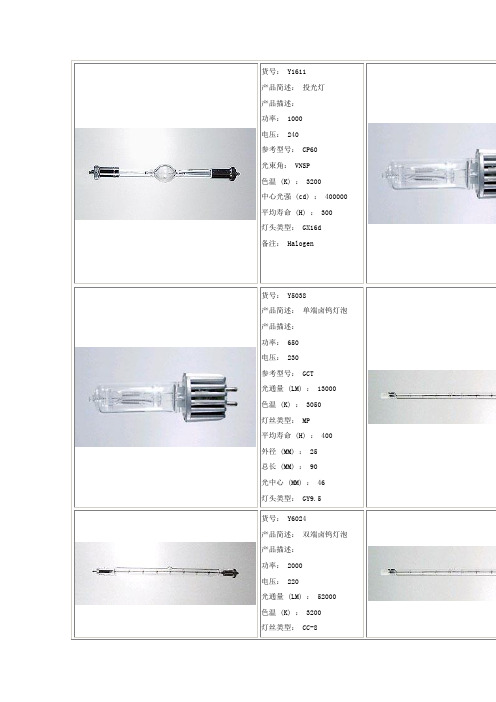
光通量(LM):52000
色温(K):3200
灯丝类型:CC-8
平均寿命(H):150
外径(MM):26.5
总长(MM):131
灯头类型:M6
货号:Y7002
产品简述:白炽灯泡
产品描述:
功率:2000
电压:220
光通量(LM):41000
燃点方式:S45
灯光类型:聚光
平均寿命(H):75
光通量(LM):49000
色温(K):5600
平均寿命(H):400
总长(MM):115
灯头类型:SFc10
货号:Y1611
产品简述:投光灯
产品描述:
功率:1000
电压:240
参考型号:CP60
光束角:VNSP
色温(K):3200
中心光强(cd):400000
平均寿命(H):300
灯头类型:GX16d
备注:Halogen
货号:Y5032
产品简述:单端卤钨灯泡
产品描述:
功率:500
电压:120
参考型号:FRG
光通量(LM):13000
色温(K):3200
灯丝类型:MP
平均寿命(H):150
外径(MM):25
总长(MM):90
光中心(MM):46.5
灯头类型:GY9.5
货号:Y5038
产品简述:单端卤钨灯泡
产品描述:
功率:650
电压:230
参考型号:GCT
光通量(LM):13000
色温(K):3050
灯丝类型:MP
外径(MM):152
总长(MM):215
光中心(MM):140
灯头类型:E40/45
避雷器-专用-66kV
国家电网公司集中规模招标采购(项目单位名称)kV (工程名称)变电站工程66kV金属氧化物避雷器招标文件(技术规范专用部分)设计单位:年月目录货物需求及供货范围一览 (1)1 图纸资料提交单位 (2)2 工程概况 (2)3 使用条件与技术参数要求 (2)4 技术差异表 (5)附录A 销售及运行业绩表 (7)附录B 技术参数通用部分条款变更表 (7)附录C 最终用户的使用情况证明 (7)附录D 投标人提供的试验检测报告表 (7)附录E 投标人提供的鉴定证书表 (8)表1货物需求及供货范围一览表2必备的备品备件、专用工具和仪器仪表供货表表3推荐的备品备件、专用工具和仪器仪表供货表1图纸资料提交单位经确认的图纸资料应由卖方提交表4所列单位。
表4卖方提交的须经确认的图纸资料及其接收单位2工程概况2.1项目名称:2.2项目单位:2.3工程规模:2.4工程地址:2.5交通、运输:3使用条件与技术参数要求3.1使用条件表5使用条件表投标人应认真逐项填写技术参数响应表中投标人保证值,不能空格,也不能以“响应”两字代替,不允许改动招标人要求值。
如有差异,请填写技术差异表。
“投标人保证值”应与型式试验报告及其他性能试验报告相符。
3.2技术参数表6.166kV交流系统用瓷套式无间隙金属氧化物避雷器基本参数表6.266kV交流系统用复合外套无间隙金属氧化物避雷器基本参数3.3技术参数补充除满足本技术规范3.2条要求的技术参数外,卖方还应如实填写下列的技术参数补充表。
表7技术参数补充表4技术差异表投标人提供的产品技术规范应与本招标文件中规定的要求一致。
若有差异投标人应如实、认真地填写差异值;若无技术差异则视为完全满足本技术规范的要求,且在技术差异表中填写“无差异”。
表8技术差异表附录A销售及运行业绩表附录B 技术参数通用部分条款变更表注本表是对技术规范通用部分的补充和修改,如有冲突,应以本表为准。
附录C 最终用户的使用情况证明注使用情况证明需有投运前后的测试数据附录D 投标人提供的试验检测报告表附录E 投标人提供的鉴定证书表。
VAL-MS 230 1+1-FM 类型2闸电压放电器说明书
VAL-MS 230/1+1-FMhttps:///gb/products/280443212/30/2019 Page 1 / 11Type 2 surge arrester - VAL-MS 230/1+1-FM - 2804432Please be informed that the data shown in this PDF Document is generated from our Online Catalog. Please find the complete data in the user's documentation. Our General Terms of Use for Downloads are valid (/download)Surge arrester for 3-conductor power supply systems (L1, N, PE), consisting of a base element with remoteindication contact and protective connectors, for mounting on NS 35.Your advantagesWith or without floating remote indication contact Mechanical coding of all slotsMulti-channel type 2 arrestersType 2 consistent plug-in surge arresters Disconnect device on each individual plugOptical, mechanical status indication for the individual arrestersKey Commercial DataTechnical dataDimensionsAmbient conditionshttps:///gb/products/280443212/30/2019 Page 2 / 11Type 2 surge arrester - VAL-MS 230/1+1-FM - 2804432Technical dataAmbient conditionsGeneralProtective circuithttps:///gb/products/280443212/30/2019 Page 3 / 11Type 2 surge arrester - VAL-MS 230/1+1-FM - 2804432Technical dataProtective circuitIndicator/remote signalingConnection datahttps:///gb/products/280443212/30/2019 Page 4 / 11Type 2 surge arrester - VAL-MS 230/1+1-FM - 2804432Technical dataConnection dataUL specificationsUL indicator/remote signalingUL connection dataStandards and RegulationsEnvironmental Product Compliancehttps:///gb/products/280443212/30/2019 Page 5 / 11Type 2 surge arrester - VAL-MS 230/1+1-FM - 2804432Technical dataEnvironmental Product ComplianceDrawingsCircuit diagramhttps:///gb/products/280443212/30/2019 Page 6 / 11Type 2 surge arrester - VAL-MS 230/1+1-FM - 2804432Dimensional drawingClassificationseCl@ssETIMUNSPSChttps:///gb/products/280443212/30/2019 Page 7 / 11Type 2 surge arrester - VAL-MS 230/1+1-FM - 2804432ClassificationsUNSPSCApprovalsApprovalsApprovalsCSA / CCA / UL Recognized / KEMA-KEUR / cUL Recognized / IECEE CB Scheme / ÖVE / EAC / EAC / cULus RecognizedEx ApprovalsApproval detailsCSA/services-industries/product-listing/ 13631CCA NTR-AT 1947-AUL Recognized /cgi-bin/XYV/template/LISEXT/1FRAME/index.htm FILE E 330181KEMA-KEUR 2170208.01cUL Recognized /cgi-bin/XYV/template/LISEXT/1FRAME/index.htm FILE E 330181IECEE CB Scheme / AT 2905/M1ÖVEhttps://www.ove.at/zertifizierung-pz/zertifizierungsregister/ 18583-001-14https:///gb/products/280443212/30/2019 Page 8 / 11Type 2 surge arrester - VAL-MS 230/1+1-FM - 2804432ApprovalsEACEAC-ZulassungEACRU C-DE.A*30.B01561cULus RecognizedAccessoriesAccessories BridgeWiring bridge - MPB 18/1- 2 - 2809209Wiring bridge for modules with connecting pitch 17.5 mm, 1-phase, 2-pos.Wiring bridge - MPB 18/1- 3 - 2809212Wiring bridge for modules with connecting pitch 17.5 mm, 1-phase, 3-pos.Wiring bridge - MPB 18/1- 4 - 2809225Wiring bridge for modules with connecting pitch 17.5 mm, 1-phase, 4-pos.https:///gb/products/280443212/30/2019 Page 9 / 11Type 2 surge arrester - VAL-MS 230/1+1-FM - 2804432AccessoriesWiring bridge - MPB 18/1- 6 - 2748564Wiring bridge for modules with connecting pitch 17.5 mm, 1-phase, 6-pos.Wiring bridge - MPB 18/1- 7 BU - 2856278Wiring bridge for modules with connecting pitch 17.5 mm, 1-phase, 7-pos., color: BlueWiring bridge - MPB 18/1- 8 BU - 2858470Wiring bridge for modules with connecting pitch 17.5 mm, 1-phase, 8-pos., color: BlueWiring bridge - MPB 18/1- 8 - 2748577Wiring bridge for modules with connecting pitch 17.5 mm, 1-phase, 8-pos.Wiring bridge - MPB 18/1- 9 - 2748580Wiring bridge for modules with connecting pitch 17.5 mm, 1-phase, 9-pos.12/30/2019 Page 10 / 11Type 2 surge arrester - VAL-MS 230/1+1-FM - 2804432AccessoriesWiring bridge - MPB 18/1-12 - 2748593Wiring bridge for modules with connecting pitch 17.5 mm, 1-phase, 12-pos.Device markingZack marker strip - ZBN 18:UNBEDRUCKT - 2809128Zack marker strip, Strip, white, unlabeled, can be labeled with: CMS-P1-PLOTTER, PLOTMARK, mounting type:snap into tall marker groove, for terminal block width: 18 mm, lettering field size: 18 x 5 mm, Number of individual labels: 5Feed-through terminal blockFeed-through terminal block - DK-BIC-35 - 2749880Feed-through terminal block for VAL and FLT applicationsLabeled device markerMarker for terminal blocks - ZBN 18,LGS:ERDE - 2749589Marker for terminal blocks, Strip, white, labeled, Horizontal: Grounding symbol, mounting type: snap into tall marker groove, for terminal block width: 18 mm, lettering field size: 18 x 5 mm, Number of individual labels: 5Marker for terminal blocks - ZBN 18,LGS:L1-N,ERDE - 2749576Marker for terminal blocks, Strip, white, labeled, Horizontal: L1, L2, L3, N, GND, mounting type: snap into tall marker groove, for terminal block width: 18 mm, lettering field size: 18 x 5 mm, Number of individual labels: 5Marker pen12/30/2019 Page 11 / 11Type 2 surge arrester - VAL-MS 230/1+1-FM - 2804432AccessoriesMarker pen - B-STIFT - 1051993Marker pen, for manual labeling of unprinted Zack strips, smear-proof and waterproof, line thickness 0.5 mmSpare partsType 2 surge protection plug - VAL-MS 230 ST - 2798844Surge protection connector type 2 with high-capacity varistor for VAL-MS base element, thermal monitoring, visual fault warning. Design: 230 V ACType 2 surge protection plug - F-MS 12 ST - 2817990Surge protection plug type 2, with N-PE total current spark gap for base element.Phoenix Contact 2019 © - all rights reserved VAL-MS 230/1+1-FM。
