AlSi10MnMg薄壁铝合金件压铸流动行为及其组织力学性能
薄壁铝合金压铸充型沿程的组织与力学性能

2 Col e f e h nc l n e il E gn eig Hu a nv r t, h n s a4 0 8 , hn ) . l g M c a i d hc n ie r , n nU ies C a g h 1 0 2 C ia e o aa V e n i y
Ab t a t h h n wa l S 1 M n g au n m l y s mp e r r p r d b g r s u e d ec si g T e e e t sr c :T e t i — l A1 i 0 M l mi u a l a l swe ep e a e y hih p e s r i a t . h f cs o n
h g e s e d e c si g c n ii n i h pr s ur l a tn o d to s Pr e i C a O a
Z HU — L u . i g 一, I Xio 一, A G h i i g 一, HANG iq a g ’ Bi Wu 一, IL o x n L U a W N S u— n Z p L —in l
me al g a h c tc n q e ,d n i a u e e ta d t n i e t . e r s l h w h t wi h o rn e e au e t l rp i e h i u s e st me s r m n n e sl t ss Th e u t s o t a , t t e p u i g t mp r t r o y e s h
d cessfsyadte cessb th ( ) ri s ei is nf a tT eu i t t ses e g n ln ao erae r l ni rae, u eaA1ga i i icn. h lma ni n t ade gt n it n h n t n z sn g i t ee l t r h o i
固溶处理过程中变质AlSi10MnMg压铸铝合金的组织演化及其对力学性能的影响
Trans. Nonferrous Met. Soc. China 29(2019) 919−930Microstructure evolution of modified die-cast AlSi10MnMg alloy during solution treatment and its effect on mechanical propertiesZi-hao YUAN1, Zhi-peng GUO1, Shou-mei XIONG1,21. School of Materials Science and Engineering, Tsinghua University, Beijing 100084, China;2. State Key Laboratory of Automobile Safety and Energy, Tsinghua University, Beijing 100084, ChinaReceived 7 May 2018; accepted 7 January 2019Abstract: To optimize the solution treatment process of a modified high-pressure die-cast AlSi10MnMg alloy, the influence of the solution treatment on the microstructure, mechanical properties and fracture mechanisms was studied using OM, SEM, EBSD and tensile test. The experimental results suggest that the solution treatment could be completed in a shorter time at a temperature much lower than the conventional practice. Surface blistering could be avoided and substantial strengthening effect could be achieved in the following aging process. Prolonging solution treatment time and elevating solution temperature would be meaningless or even harmful. The rapid evolution of eutectic silicon during solution treatment, especially at the early stage, affected the way of interaction among α-Al grains during plastic deformation, and changed the ultimate mechanical properties and fracture mode.Key words: AlSi10MnMg alloy; die casting; solution treatment; microstructure evolution; mechanical properties; process optimization1 IntroductionHigh-pressure die casting (HPDC) is one of the most efficient casting processes for mass production of shaped components. Due to extremely high interfacial heat transfer coefficient [1], the melt solidifies at a high cooling rate, leading to a very refined microstructure and better mechanical properties. However, the complicated flow pattern [2] for thin-walled castings would lead to air entrapment or gas pores, which significantly decreases the ultimate mechanical properties of the component. Besides, the sub-surface gas pores would cause surface blisters during conventional solution treatment (4−10 h at 540 °C for Al−Si−Mg alloys [3−5]), which follows the principle of high temperature and long time to homogenize the alloy elements.Both vacuum-assisted and pore-free die casting could reduce the gas porosity significantly [6,7]. Recent studies [8−11] have also demonstrated that a low temperature solution treatment could reduce surface blisters, and the subsequent artificial aging could improve the tensile strength significantly. Mostly processed by HPDC, the modified AlSi10MnMg alloy has been widely used in automobile industry due to its excellent castability and mechanical performance. Mg could promote the formation of strengthening phases, e.g., Mg2Si at the inter-granular boundary of the as-cast microstructure. In order to further improve the mechanical properties, the Mg2Si phase must dissolve into the α-Al matrix and precipitate as nano-size meta-stable phases inside the grains [12−15].Extensive studies have been performed to investigate the effect of solution treatment on the microstructure and mechanical properties of the cast Al−Si−Mg alloys. The best solution treatment process parameters varied within a wide range, which strongly depend on the alloy composition [16,17], morphology of eutectic silicon [17−19] and manufacture process [4,5]. And the solution treatment affected the final mechanical performance through dissolving and homogenizing alloy elements [16,19,20], as well as changing silicon phase [19,21].Due to the advantages and disadvantages of the die- cast alloys, the optimized solution treatment parameters should be revised, following different principles fromFoundation item: Project (U1537202) supported by the National Natural Science Foundation of China; Project (BA2015041) supported by the Special Funding Program on Transformation of Scientific and Technological Achievements in Jiangsu Province, ChinaCorresponding author: Shou-mei XIONG; Tel: 86-10-62773793; Fax: 86-10-62770190; E-mail: smxiong@DOI:10.1016/S1003-6326(19)65001-6Zi-hao YUAN, et al/Trans. Nonferrous Met. Soc. China 29(2019) 919−930 920that of conventional heat treatment. Very refined microstructure makes it possible to shorten the solution treatment process at a relatively low temperature, which also reduces the risk of blisters. For the heat treatment of a modified AlSi10MnMg high-pressure die-cast alloys, detailed studies need to be performed to optimize the process parameters. In this work, quantitative analysis was performed on the microstructure evolution and mechanical properties during the solution treatment. In-situ tensile deformation together with fractography analysis was performed to reveal the fracture mode and crack expansion. The process−microstructure−property relationship was investigated, together with the discussion on the optimization of process parameters.2 ExperimentalThe composition of the modified AlSi10MnMg alloy used in this study is listed in Table 1. Si would improve the flowability of the alloy and reduce the risk of hot cracking. The content of Mg is 0.301 wt.% to ensure a distinct strengthening effect, and all the β-Mg2Si phases could dissolve into the α-Al matrix at a relatively low solution temperature. Sr could modify the morphology of the eutectic silicon. The content of Fe was as low as 0.109 wt.% to reduce the brittle needle-like iron-rich β-Al5FeSi during solidification, but at the risk of die soldering. As a compensation, Mn was added into the alloy to reduce die soldering.The HPDC components were produced by using a TOYO BD−350V5 cold chamber die casting machine with key processing parameters listed in Table 2. Oil was circulated inside the dies to stabilize the temperature (at ~120 °C). Figure 1 shows the configuration of the die casting, which comprised 3 bars and 1 plate of 170 mm ×30 mm ×2.5 mm. Detailed configuration of the cylindrical tensile specimen is shown in Fig. 1(b).Table 1 Composition of modified AlSi10MnMg alloy (wt.%)Si Mg Mn Fe Cu Sr Ti Zn Al 10.14 0.301 0.639 0.109 0.016 0.025 0.073 0.007 Bal.Table 2 Key processing parameters of die castingParameter ValueMelt temperature/°C 700Slow shot speed/(m∙s−1) 0.15Gate speed/(m∙s−1) 57.9 Intensification pressure/MPa 79Vacuum degree/kPa ~90The tensile testing bars were put into an electric- resistance muffle furnace at 490 °C for 5, 15, 30, 60, 120, 300, 720 and 1440 min for heat treatment followed by an immediate water quenching. As a comparison, some bars were solutionized at 520 and 540 °C for 30 min, respectively. Artificial aging process was performed at 200 °C for 2 h immediately after quenching to achieve the maximum strength (T6 state).Fig. 1 Configuration of die casting with 3 bars and 1 plate (a), dimensions of tensile testing bar (b) and tensile plate (c) for in-situ observation (unit: mm)Zi-hao YUAN, et al/Trans. Nonferrous Met. Soc. China 29(2019) 919−930 921 Several sections of samples were polished andobserved using OM (optical microscope). And the OM images were used to calculate the porosity of each sample with ImageProPlus software. To investigate the microstructure evolution, the die-cast and the water- quenched samples were ground, polished, etched with Keller’s etchant and observed usin g a JEOL 7001F SEM. The specimens for EBSD were prepared with the method of ion milling.Mechanical properties of the as-cast state, as-quenched state and/or T6 state alloys were investigated. The yield strength (YS), ultimate tensile strength (UTS) and elongation to fracture were measured at room temperature with a strain rate of 0.0005 s−1. A 50-mm extensometer was used to measure the elongation within the gauge length. To study the fracture mode transfer due to solution treatment, the fracture surfaces of the tensile specimens were investigated using a JEOL 7001F SEM after ultrasonic cleaning in acetone.In order to study the plastic deformation, in-situ tensile samples were prepared from the 2.5-mm thick plate (see Fig. 1(a)) using electrical discharge machining.A 0.3-mm notch was made on the sample to imitate the fatal defect inside the components during service, and facilitate the nucleation of crack. The die-cast and T6-state in-situ samples were ground, polished and etched. In-situ tensile deformation was performed in a SEM chamber with a grip moving speed of 0.1 μm/s.3 Results3.1 Microstructure evolution during solutiontreatmentFigure 2 shows the sections and appearances of tensile bars before and after solution treatment. The porosity was originally about 0.41% in the as-cast tensile bar (see Fig. 2(a)), which slightly went up to 0.52% after 300 min solution treatment (see Fig. 2(b)), and 0.56% after 720-min solution treatment (see Fig. 2(c)). The increase in porosity was generally attributed to the expansion of gas pores [8,9]. Tensile bars were bent because of the gravitational creep after 720-min solution treatment (see Fig. 2(d)). Due to good vacuum degree and relatively low solution temperature, no obvious surface blisters were found until 1440-min solution treatment (see Fig. 2(e)). The solution temperature of 540 °C, which was ordinarily used in conventional practice, caused blisters after only 30 min (see Fig. 2(f)).Figure 3 shows a typical microstructure of a modified high-pressure die-cast AlSi10MnMg alloy and a magnified view of modified eutectic Si. Because of the high cooling rate during solidification, most eutectic phases exhibited a divorced morphology. The externally solidified crystals (ESCs), which originally nucleated inside the shot sleeve, could be observed on the section of casting (see Fig. 3(a)). The α-Al grains, with a size ofFig. 2 Sections (a−c) and appearance (d−f) of tensile barsZi-hao YUAN, et al/Trans. Nonferrous Met. Soc. China 29(2019) 919−930 922Fig. 3 Typical microstructure of as-cast modified AlSi10MnMg alloy (a) and magnified view of modified eutectic Si (b)15−40 μm, exhibited a globular or dendritic morphology. The fibrous eutectic silicon exhibited a coarse surface (see Fig. 3(b)), which was mostly caused by the modification of Sr. The diameter of the eutectic Si was only 100−300 nm, while its length could be several microns. The Si fibers were deeply embedded into the α-Al matrix, and distributed at the boundaries of large α-Al grains. The β-Mg2Si phase was also found in the eutectic region, as marked by the circle in Fig. 3(b).The influence of the solution treatment time on the microstructure of the alloy and its average diameter as function of solution treatment time at 490 °C was shown in Fig. 4. A small part of β-Mg2Si phases were still not completely dissolved into the matrix after solution treatment at 490 °C for 5 min and fibrous Si changed into particles or short rods (see Fig. 4(a)). The dendrite arms of large α-Al grains coalesced, with Si particles packed in. Some particles forming clusters distributed in α-Al grains. Those particles would detach from the α-Al matrix when deeply etched, generating holes on the polished surface of the samples (see Figs. 4(a−e)). All the β-Mg2Si phases disappeared after solution treatment for 15 min (see Fig. 4(b)). Thus, the solution temperature of 490 °C was sufficient to dissolve all the β-Mg2Si phases in this alloy due to the low content of Mg.As coarsening occurred, the interface between the α-Al matrix and the silicon particles became smooth. During the solution treatment, the average diameter of silicon particles increased rapidly within the first 30 min, i.e., from 0.2 to 1.68 μm, after which it increased rather slowly, i.e., the average diameter increased to only ~2.8 μm after 1 d (1440 min) of solution treatment (see Fig. 4(e)).The grain boundaries could be recognized in the EBSD image quality maps (see Figs. 5(a−e)), according to which the average grain sizes of α-Al matrix could be calculated (see Fig. 5(f)). Over 500 grains at the center of the bar were taken for the statistical analysis in each sample. The statistical average grain area increased rapidly in the first 60 min of solution treatment. That was the result of the disintegration of eutectic silicon. Meanwhile, some dendrite grains still existed (see Fig. 5(b)). After that, the grain size grew slowly. Nearly all grains exhibited a granular morphology, which indicated the coalescence of dendrite arms that eliminated the inner boundaries.3.2 Mechanical propertiesThe samples were deflected and/or blistered after 720-min solution treatment, which would fail in obtaining the uniform uniaxial tensile stress during tensile test. Thus, the corresponding tensile tests were not performed. Figure 6 shows the mean values of YS, UTS and elongation as a function of solution treatment time. The dash line in each figure indicated the mechanical properties of the die-cast state. The first point of each curve corresponded to the solution time of 5 min. The dash line in each figure, i.e., 161 MPa for YS, 314 MPa for UTS, and ~7.5% for elongation, represented the values of the die-cast state.A 5-min solution treatment could reduce both YS and UTS and increase the elongation significantly. However, longer solution treatment produced negligible effect on the as-quenched yield strength which just fluctuated between 98 and 107 MPa (see Fig. 6(a)). The UTS of as-quenched samples increased from 228 MPa at 5 min, to the maximum of 245 MPa at 30 min, then decreased slowly to 232 MPa at 300 min (see Fig. 6(b)). The elongation of as-quenched samples increased from 13% at 5 min, to the maximum of 21% at 30 min, and then decreased slowly to 16% at 300 min (see Fig. 6(c)).A T6-treatment improved both YS and UTS significantly, but reduced elongation. The YS increased significantly from 192 to 257 MPa at treatment time from 5 to 15 min, after which the YS maintained rather stable with a slight decrease to 245 MPa at 300 min. The UTS of the T6 samples increased from 275 MPa at 5 minZi-hao YUAN, et al/Trans. Nonferrous Met. Soc. China 29(2019) 919−930 923Fig. 4 Microstructures of modified die-cast AlSi10MnMg alloy after solution treatment at 490 °C for different time (a −e) and average diameter as function of solution treatment time at 490 °C (f)to the maximum of 326 MPa at 15 min, and then decreased slowly to 302 MPa at 300 min (see Fig. 6(b)). The elongation increased from 10% at 5 min to the maximum of 13% at 30 min, and then decreased slowly to 9.5% at 300 min (see Fig. 6(c)). As a comparison, the YS, UTS and elongation of 520 °C-solutionized T6 bars were 257 MPa, 329 MPa and 11%, respectively, which have no distinct improvement over the 490 °C- solutionized ones.During the age process, the main microstructure transformation was the precipitation reaction [12,15,22], which turned the α-Al grains from homogeneous solid solution to the phase reinforced with precipitates inside. Those brittle precipitates could hinder the movement of dislocations during plastic deformation. Thus, the aging process improved the strength but lower the elongation compared with that of the as-quenched samples. However, the elongation of T6 state is still higher than that of as-cast state (see dash line in Fig. 6(c)). 3.3 FractographyFigure 7 shows the fracture surface observed using SEM after the tensile test. Without solution treatment, the fracture surface exhibited more brittle features. The modified fiber-like eutectic Si, embedded deeply in the α-Al matrix, and cracked during the tensile test (see Fig. 7(a)). The fracture mode changed as the solution treatment time increased. After 5-min solution treatment, some shallow dimples started to emerge on the fracture surface (see Fig. 7(b)). After solution treatment of 30 min, the fracture surface exhibited a uniform distribution of small dimples of ~2.5 μm (see Fig. 7(c)). Prolonged solution treatment, i.e., 300 min, only enlarged the dimple size to ~5 μm (see Fig. 7(d)). Some spherical Si particles sat at the bottoms of the dimples, as marked by the arrows in Fig. 7(d).3.4 In-situ observation of deformation and crackFigure 8 shows a typical microstructure duringZi-hao YUAN, et al/Trans. Nonferrous Met. Soc. China 29(2019) 919−930924Fig. 5 EBSD image quality maps of as-cast specimen (a) and specimens solutionized at 490 °C (b−e), and evolution of average grain area of α-Al matrix versus solution time at 490 °C (f)Fig. 6 Mechanical properties of as-cast, as-quenched and T6 samples after solution treatment at 490 °C: (a) Yield strength (YS); (b) Ultimate tensile strength (UTS); (c) Elongationin-situ tensile deformation. All the view fields were at the crack tip, where severe plastic deformation occurred. In the die-cast sample (see Figs. 8(a) and (b)), the α-Al grains exhibited clear and uniform slip bands, indicatinga uniform plastic deformation. The slip bands stopped in the eutectic region at the α-Al grain boundary. The eutectic silicon was too stiff to deform continuously and harmoniously with the α-Al grains, thus micro-cracksZi-hao YUAN, et al/Trans. Nonferrous Met. Soc. China 29(2019) 919−930 925Fig. 7 Fracture surfaces of as-cast sample (a) and T6-treated samples at different solution time (b −d)Fig. 8 Deformation at main crack during in-situ tensile test for as-cast (a, b) and T6-treated (c, d) samples ((b) is magnified view of red square in (a), and (d) is magnified view of red square in (c))generated. Both interface decohesion and brittle cracks could be observed (see Fig. 8(b)), i.e., as deformation proceeded, the crack expanded rapidly along the grain boundaries, as shown in Fig. 9(a).In the T6-state sample (see Figs. 8(c) and (d)), thepolished surface of specimen was significantly disturbed at the crack tip. The α-Al grains still remained the capability of slipping after precipitation reaction because the low content of Mg limited the amount of strengthening precipitates. The slip bands wereZi-hao YUAN, et al/Trans. Nonferrous Met. Soc. China 29(2019) 919−930 926Fig. 9Grain boundaries after deformation for as-cast (a) and T6-treated (b) samplesdisordered, coarse and prone to bifurcate. In Fig. 8(d), the Si particles scattered in the α-Al matrix, indicating the presence of the eutectic before solution treatment. The intricate fiber-like Si network collapsed, and the slip bands could propagate deeply into the eutectic region. Without large aspect ratios and coarse interfaces, most Si particles detached from the α-Al matrix at the interface due to deformation mismatch (see Fig. 8(d)). The plastic deformation smoothly transmitted from grain to grain, or from one dendrite arm to another without inter- granular cracking (see Fig. 9(b)). Meanwhile, small cracks generated at the interface, and became larger when external load was amplified. These minor cracks could act as the potential precursors of the main crack, thus the main crack expanded in zigzags and branched occasionally.4 Discussion4.1 Optimization of solution treatment temperatureConventional practice suggests that ~540 °C is a recommended solution temperature for Al−Si−Mg alloy [4,5,23], in order to shorten the solution time. However, the risk of gas pore expansion and blistering was not taken into consideration because there are no high pressure gas pores inside the traditional castings. As shown in Fig. 2(f), blistering happened on the surface of die-cast tensile test bar only after solution treatment at 540 °C for 30 min.The main concern of solution treatment of die castings is to finish solutionizing before serious pore expansion and blistering. One logical adjustment is lowering the solution temperature, at which the gas pressure in pores remains relatively low and the alloy still has competent strength to delay the pore expansion and blistering. In this study, most solution treatments were carried out at 490 °C, which was ~75 °C lower than the solidus line and ~67 °C lower than the eutectic reaction temperature (see Fig. 10). The experimental result indicated that distinct pore expansion happened very late at 490 °C (Figs. 2(b) and (c)). Besides, 490 °C was estimated to be just slightly higher than the solvus line to ensure the complete dissolution of β-Mg2Si phases, according to Fig. 10 [24,25]. Solution treatment experiment demonstrated that it took a short time to finish the dissolution of β-Mg2Si phases and the spheroidization of the eutectic silicon (see Fig. 4). Substantial improvement on mechanical properties could be achieved after aging process (see Fig. 6). The tensile test also demonstrated that the mechanical properties of 520 °C-solutionized T6-state bars have no distinct improvement over those of the 490 °C-solutionized ones.Fig. 10 Computed vertical sections of phase diagram of Al−Mg−Si alloy with 90 wt.% Al [24,25]The experiment mentioned above demonstrated that the solution treatment of die castings could be finished at a low temperature in a short time. That was the result of the fine microstructure of die castings (see Fig. 3). According tolaw, the evaluated diffusion distances, i.e.,were about 11.3 and 9.4 μm respectively, for Mg and Si, where D was the diffusion coefficient in α-Al matrix at solution temperature of 763 K [26], and t=900 s was the solution time. These distances exceeded the average dendrite arm radius, i.e.,Zi-hao YUAN, et al/Trans. Nonferrous Met. Soc. China 29(2019) 919−930 927about 8 μm (see Figs. 4(a) and 5(a)), indicating that it was close to the completion of homogenization across the dendrite arms when the solution time was 15 min.4.2 Silicon evolution during solution treatmentAltering the morphology of the eutectic silicon is one of the most important aims of solution treatment. Modified with Sr, the flaky Si turned into fiber-like morphology, which had been extensively studied [27,28]. The observation of deeply etched sample showed that the eutectic Si fibers were connected (see Fig. 3). However, the microstructure was unstable due to the vast and complicated interface between α-Al grains and Si fibers. The modified Si was easier to fragment, as shown in Ref. [29].The microstructure evolution is driven by the minimization of the total free energy of the system. This was achieved by reducing the interface area between Si phase and α-Al matrix [30]. As a result of the Rayleigh − Taylor surface instability, unstable perturbations increased in amplitude before the connected area finally pinched off, and the fibrous silicon fragmented into discrete droplets [31,32]. The second stage was spheroidization, during which the droplets tended to decrease the interfacial curvature. Capillarity-induced diffusion gave rise to the apparent flux of solute from the region with high curvature to that with low curvature [33] as a result of Gibbs −Thomson effect. In that way, the specific interface area was reduced. Further reduction in interfacial energy of the system was accomplished with larger particles growing and smaller particles shrinking, i.e., the Ostwald ripening [34]. The growth of the silicon particles followed the traditional LSW (Lifshitz −Slyozow −Wagner) theory [35]:ktR R =-303(1)where t is the time, R is the averageradius of the particles, 0R is the initial average radius at t =0, and k is a constant. The evolution of the average radius of the particles fitted very well with Eq. (1) after 30-min solution treatment (see Fig. 11, the square of correlation coefficient of this linear regression is 0.993). The evolution of the silicon particles was a combination of fragmentation, spheroidization and Oswald ripening. As the Oswald ripening proceeded, the distribution of the particle radius was adjusted asymptotically following the LSW theory.4.3 Effect of microstructure evolution on deformationand crackingThe morphology of the eutectic Si particles had a great influence on the mechanical properties of the alloy. As a brittle phase, the Si could either strengthen the matrix or promote crack nucleation.Fig. 11 Cube of equivalent eutectic Si radius vs solution timeFor die-cast specimen, the eutectic was divorced (see Fig. 3) as a consequence of extremely high cooling rate [1]. The configuration signified that the silicon − fiber-reinforced Al-matrix composite filled the inter-dendritic arm space and the inter-granular space of the α-Al grains. The hard, brittle and semi-continuous (see Fig. 3(b)) silicon fibers comprised the skeleton to sustain the whole material and provided a great strengthening effect. The complicated interface between α-Al grains and Si fibers ensured the sturdy cohesion. When external force exerted on the specimen, the fiber-like Si could bear a lot of load due to its higher elastic modulus and inflexibility for yield. So, the die-cast specimen exhibited a relatively high strength. On the other hand, the Si particles isolated the plastic α-Al grains from each other (see Fig. 3(a)), and the plastic deformation in one α-Al grain could not be compatible with that in its neighbors (see Figs. 8(a) and (b)), i.e., the potential ductility was significantly suppressed. As the external force increased, the plastic incompatibility between silicon fibers and α-Al grains would ultimately lead to either silicon cracking or interface decohesion (see Fig. 8(b)), leading to an elongation of only ~7.5% (see Fig. 6(c)).The skeleton began to decompose after 5-min solution treatment at 490 °C via necking and fragmentation of the fiber-like Si (Fig. 4(a)). The contribution of solute Mg atoms to yield strength is estimated to be less than 13 MPa, with the equation in Ref. [36]. The strengthening effect of the Si particles with small aspect ratio and smooth surface was much lower than that of the fibrous Si. Accordingly, both YS and UTS would decrease whereas the elongation increased (see Fig. 6). The fracture mode also changed during the 5-min solution treatment (see Fig. 7(b)). However, 5-min solution treatment was not enough to dissolve all the β-Mg 2Si phases (see Fig. 4(a)), so the following artificial age could not make full use of Mg atoms in this alloy to strengthen the α-Al matrix.Zi-hao YUAN, et al/Trans. Nonferrous Met. Soc. China 29(2019) 919−930 928After fragmentation and spheroidization during 30-min solution treatment (see Fig. 4(c) and Fig. 7(c)), the α-Al grains joined together to form a continuous matrix. Discontinuous Si droplets could not hinder all the moving dislocations across the borders, and neighboring α-Al grains cooperated with each other efficiently during plastic deformation (see Figs. 8(c) and (d)). After the dissolution of β-Mg2Si phase, both Mg and Si atoms precipitated as meta-stable phases in the α-Al grains during artificial age [12,15,22]. The corresponding T6-state strength reached the maximum value. Prolonged solution time could not provide higher supersaturation after water quenching. Thus, the strengthening effect of precipitation kept constant. However, the α-Al grains coarsened (see Fig. 5(f)), which weakened the alloy strength according to Hall−Patch equation. Thus, the combined effect led to the decrease in mechanical properties (see Fig. 6).When plastic deformation occurred, the dislocations in α-Al grains moved forward to the grain boundaries, and stopped when encountering the Si particles. Further deformation and dislocation accumulation caused stress concentrations at the interface between α-Al grains and Si particles [21,37]. When stress concentrations exceeded some critical values, crack would initiate either in the silicon particles or at the interface (see Fig. 8(d)). The actual crack mode was a very local event as a result of many factors [37]. According to the in-situ observation (see Fig. 8(d)), the latter cracking mode became dominant for the heat-treated specimen. The Si particles bound loosely with the α-Al matrix. And because the micro-cracks could grow and expand along the interfaces, the Si particles were removed from the α-Al matrix. Further deformation would lead to the join of the micro-cracks as well as the nucleation of new micro-cracks until the final fracture, leaving Si particles at the bottom of the dimple (see Fig. 7(d)).After spheroidization, shorter solution treatment would be more beneficial to the ductility of the material due to smaller particles, shorter inter-particle spacing and larger population of particles. Firstly, despite their lack of the capacity for plastic deformation, those small spherical particles were more flexible to minimize the plastic incompatibility with matrix through movement and rotation (see Fig. 8(d)). Thus, the nominal stress required for particle cracking increased as particle size decreased [37]. Secondly, shorter inter-particle spacing implied shorter mean free path, less dislocation accumulation [38] at interface and lower stress concentration before the initial cracking. Regardless of the cracking mode, the size of the micro-crack reflected the magnitude of deformation incompatibility between the particles and the matrix. The stress concentration factor was proportional to the square root of the crack size, thus smaller inter-particle spacing would lead to smaller micro-cracks and lower stress concentration. Thirdly, severe plastic deformation would occur in front of the tip of cracks. Keeping constant volume fraction of particles during coarsening process, larger population of particles would lead to more micro-cracks. The deformed regions in front of micro-cracks would absorb more energy by work hardening. In this respect, large population of micro-cracks dispersed the plastic deformation, preventing severe strain localization and delaying the expansion of large cracks.5 Conclusions(1) Contrary to the conventional practice, the solution treatment of the die-cast AlSi10MnMg alloy should be carried out under a relatively low temperature in a shorter time. Substantial strengthening effect could be achieved in the following artificial aging process. Prolonging solution time and elevating solution temperature would be meaningless or even harmful due to microstructure coarsening, surface blistering and/or gravitational deflection.(2) The Si particles changed rapidly during solution treatment. After the fragment and spheroidization, the coarsening process of Si particles followed the LSW equation.(3) The morphology and the size of Si particles affected the mechanical properties and the fracture mode through affecting the interaction of α-Al grains. References[1]GUO Zhi-peng, XIONG Shou-mei, CHO S H, CHOI J K. Study onheat transfer behavior at metal/die interface in aluminum alloy die casting process. I: Experimental study and determination of the interfacial heat transfer coefficient [J]. Acta Metallurgica Sinica, 2007, 43: 1149−1154. (in Chinese)[2]JIA Liang-rong, XIONG Shou-mei, LIU Bai-cheng. Study onnumerical simulation of mold filling and heat transfer in die casting process [J]. Journal of Materials Science & Technology, 2000, 16: 269−272.[3]OZHOGA-MASLOVSKAJA O, GARIBOLDI E, LEMKE J N.Conditions for blister formation during thermal cycles of Al−Si−Cu−Fe alloys for high pressure die-casting [J]. Materials & Design, 2016, 92: 151−159.[4]YANG Chang-lin, LI Yuan-bing, DANG Bo, LÜ He-bin, LIU Feng.Effects of cooling rate on solution heat treatment of as-cast A356 alloy [J]. Transactions of Nonferrous Metals Society of China, 2015, 25: 3189−3196.[5]DANG Bo, LIU Cong-cong, LIU Feng, LIU Ying-zhuo, LIYuan-bing. Effect of as-solidified microstructure on subsequent solution-treatment process for A356 Al alloy [J]. Transactions of Nonferrous Metals Society of China, 2016, 26: 634−642.[6]CAO Han-xue, HAO Meng-yao, SHEN Chao, LIANG Peng. Theinfluence of different vacuum degree on the porosity and mechanical properties of aluminum die casting [J]. V acuum, 2017, 146: 278−281.[7]LI Xiao-bo, XIONG Shou-mei, GUO Zhi-peng. Improved。
热处理对压铸AlSi10MnMg合金组织和力学性能的影响

热处理对压铸AlSi10MnMg合金组织和力学性能的影响全泳琪;程汉明;王鹤睿;赵耀;林高用
【期刊名称】《有色金属科学与工程》
【年(卷),期】2022(13)2
【摘要】以国内某公司自主改进的非真空压铸AlSi10MnMg合金片状试样作为实验对象,研究不同的热处理制度对该合金组织和力学性能的影响。
结果表明:非真空压铸件经高温固溶+淬火+人工时效处理后综合性能下降,容易发生弯曲变形和鼓泡现象。
仅经低温时效处理的压铸件屈服强度和抗拉强度分别达到了251.8 MPa和327.1 MPa,较压铸态分别提高了42.6%和10.5%,断后伸长率则有所下降。
经低温时效后合金析出的主要强化相为Mn_(6)Si和Mg_(2)Si相。
【总页数】9页(P98-106)
【作者】全泳琪;程汉明;王鹤睿;赵耀;林高用
【作者单位】中南大学材料科学与工程学院;南通鸿劲金属铝业有限公司
【正文语种】中文
【中图分类】TG156;TG249.2
【相关文献】
1.热处理对流变压铸铝合金力学性能和显微组织的影响
2.热处理工艺对高真空压铸Mg–8Gd–3Y–0.4Zr镁合金组织及力学性能的影响
3.固溶处理过程中变质
AlSi10MnMg压铸铝合金的组织演化及其对力学性能的影响4.固溶处理过程中变质AlSi10MnMg压铸铝合金的组织演化及其对力学性能的影响5.半固态流变压铸AlSi10MnMg合金组织和热处理工艺试验研究
因版权原因,仅展示原文概要,查看原文内容请购买。
SLM成形AlSi10Mg合金的组织与力学性能

Material Sciences 材料科学, 2019, 9(6), 564-572Published Online June 2019 in Hans. /journal/mshttps:///10.12677/ms.2019.96072Microstructure and Mechanical Propertiesof AlSi10Mg Alloy Fabricated by SLMTechnologyXin Li1,2, Zhenghua Huang2*, Wenjun Qi2, Juan Wang1, Yajiang Li1, Jianye Liu31School of Materials Science and Engineering, Shandong University, Jinan Shandong2Guangdong-Hong Kong Joint Research and Development Center on Advanced Manufacturing Technology for Light Alloys, Guangdong Institute of Materials and Processing, Guangzhou Guangdong3Guangdong Hanbang Laser Technology Co. Ltd., Zhongshan GuangdongReceived: May 27th, 2019; accepted: Jun. 10th, 2019; published: Jun. 17th, 2019AbstractAlSi10Mg samples were fabricated by SLM technology under the process parameters where laser power, scanning speed, scanning interval and layer thickness were 450 W, 3800 mm/s, 60 μm and30 μm, respectively. Phase composition and microstructure were analyzed by XRD, OM and SEM,and meanwhile the hardness and tensile mechanical properties at ambient temperature were stu-died. The results show that the microstructure mainly consists of Al matrix, Si phase and a little Mg2Si phase. Microstructure of cross section mainly consists of uniform “band” strips. The stripe can be divided into inner fine crystal zone, heat affected zone and boundary coarse grain zone.Microstructure of longitudinal section mainly consists of uniform “U-shaped” stripes. The bounda-ries between the stripes are clear; meanwhile the stripes are divided into inner equiaxed crystal zone and boundary columnar crystal zone. The sample obtained under this parameter exhibits excellent comprehensive mechanical properties, where the tensile strength, yield strength and elongation reach 470 MPa, 327 MPa and 8.0%, respectively.KeywordsLaser Selective Melting, AlSi10Mg Alloy, Microstructure, Mechanical PropertySLM成形AlSi10Mg合金的组织与力学性能李鑫1,2,黄正华2*,戚文军2,王娟1,李亚江1,刘建业31山东大学材料科学与工程学院,山东济南2广东省材料与加工研究所,粤港轻合金先进制造技术联合研发中心,广东广州*通讯作者。
alsi10mgmn化学成分

ALSI10MGMN化学成分1. 简介ALSI10MGMN是一种铝合金,常用于制造高强度和耐腐蚀的零件。
它由铝、硅、镁和锰等元素组成,具有良好的机械性能和热处理性能。
2. 化学成分ALSI10MGMN的化学成分如下:•铝(Al):主要元素,占总质量的约90%以上。
铝具有轻质、导热性好等特点。
•硅(Si):占总质量的约9-11%。
硅可提高合金的强度和耐磨性。
•镁(Mg):占总质量的约0.2-0.45%。
镁可以提高合金的强度和韧性。
•锰(Mn):占总质量的约0.2-0.5%。
锰可以提高合金的抗腐蚀性能。
此外,ALSI10MGMN中还可能含有微量的其他元素,如铜(Cu)、锌(Zn)、铁(Fe)等。
3. 特性与应用3.1 特性ALSI10MGMN具有以下特点:•高强度:该合金经过适当热处理后,具有较高的强度和硬度。
•耐腐蚀性:铝合金具有良好的耐腐蚀性,可以在恶劣环境下长时间使用。
•良好的流动性:ALSI10MGMN在熔化状态下具有良好的流动性,适合于铸造加工。
•可焊接性:该合金易于焊接,可以通过各种焊接方法进行加工。
3.2 应用由于ALSI10MGMN具有良好的机械性能和耐腐蚀性能,因此广泛应用于以下领域:•汽车工业:ALSI10MGMN常用于制造汽车零部件,如发动机缸盖、曲轴壳体等。
其高强度和耐腐蚀性能使得零件能够承受较大的力和恶劣的工作环境。
•航空航天工业:该合金也被广泛应用于航空航天领域,制造飞机结构件、发动机零部件等。
其轻质和高强度特点符合飞行器对材料轻量化和强度要求。
•电子产业:由于ALSI10MGMN具有良好的导电性能和热传导性能,常用于制造电子设备外壳、散热器等。
•其他领域:此外,ALSI10MGMN还可用于制造运动器械、工业机械等领域的零件。
4. 加工与热处理4.1 加工ALSI10MGMN常通过铸造加工得到所需的零件。
铸造方法包括压铸、重力铸造等。
在铸造过程中,需要控制合金的熔化温度和浇注温度,以保证合金的流动性和凝固过程中的组织形成。
alsi10mg铝合金标准

alsi10mg铝合金标准ALS10MG铝合金是一种常见的铝合金材料,其材质具有良好的强度、硬度和耐腐蚀性能,被广泛应用于工业制造、建筑工程和航空航天等领域。
本文将对ALS10MG铝合金的标准进行详细介绍,包括其化学成分、机械性能、应用领域和加工工艺等方面。
ALS10MG铝合金的化学成分主要包括铝(Al),镁(Mg),锰(Mn)和硅(Si)。
其中铝是该合金的主要成分,占总质量的大部分,能够为合金提供良好的塑性和韧性。
镁和锰主要起到强化合金的作用,能够提高合金的强度和硬度。
硅主要用于调整合金的熔点和改善铸造性能。
ALS10MG铝合金具有优异的机械性能。
其抗拉强度通常在210~240MPa之间,屈服强度为170~200MPa,延伸率为8%~12%。
这些性能可以在一定程度上满足工程应用的要求。
此外,ALS10MG铝合金还具有良好的耐腐蚀性能,能够抵抗湿气、氧气和一些化学介质的腐蚀,适用于各种恶劣的工作环境。
ALS10MG铝合金具有广泛的应用领域。
在工业制造方面,它常用于制造压铸件、锻造件和铸造件等。
其良好的铸造性能使其成为铸造行业的重要材料。
在建筑工程方面,ALS10MG铝合金常用于制造门窗、幕墙和铝合金型材等。
其轻质、抗腐蚀和高强度的特点,在建筑领域得到了广泛应用。
此外,ALS10MG铝合金还可以用于制造航空航天器件、电子产品外壳和汽车零部件等。
在ALS10MG铝合金的加工工艺方面,常用的包括压铸、锻造、挤压和铸造等方法。
压铸是将熔融的铝合金注入到压铸模具中,通过快速冷却固化成型的方法。
锻造是将铝合金加热到柔软状态,然后施加压力进行塑性变形,使其达到所需形状和尺寸的方法。
挤压是将铝合金条坯经过模具挤压成型,常用于制造铝合金型材和芯棒等。
铸造是将熔融的铝合金倒入铸造模具中,通过冷却凝固成型的方法。
总的来说,ALS10MG铝合金是一种具有优良性能的铝合金材料,其化学成分、机械性能、应用领域和加工工艺等方面都值得关注。
SLM成形AlSi10Mg合金的组织与力学性能
Material Sciences 材料科学, 2019, 9(6), 564-572Published Online June 2019 in Hans. /journal/mshttps:///10.12677/ms.2019.96072Microstructure and Mechanical Propertiesof AlSi10Mg Alloy Fabricated by SLMTechnologyXin Li1,2, Zhenghua Huang2*, Wenjun Qi2, Juan Wang1, Yajiang Li1, Jianye Liu31School of Materials Science and Engineering, Shandong University, Jinan Shandong2Guangdong-Hong Kong Joint Research and Development Center on Advanced Manufacturing Technology for Light Alloys, Guangdong Institute of Materials and Processing, Guangzhou Guangdong3Guangdong Hanbang Laser Technology Co. Ltd., Zhongshan GuangdongReceived: May 27th, 2019; accepted: Jun. 10th, 2019; published: Jun. 17th, 2019AbstractAlSi10Mg samples were fabricated by SLM technology under the process parameters where laser power, scanning speed, scanning interval and layer thickness were 450 W, 3800 mm/s, 60 μm and30 μm, respectively. Phase composition and microstructure were analyzed by XRD, OM and SEM,and meanwhile the hardness and tensile mechanical properties at ambient temperature were stu-died. The results show that the microstructure mainly consists of Al matrix, Si phase and a little Mg2Si phase. Microstructure of cross section mainly consists of uniform “band” strips. The stripe can be divided into inner fine crystal zone, heat affected zone and boundary coarse grain zone.Microstructure of longitudinal section mainly consists of uniform “U-shaped” stripes. The bounda-ries between the stripes are clear; meanwhile the stripes are divided into inner equiaxed crystal zone and boundary columnar crystal zone. The sample obtained under this parameter exhibits excellent comprehensive mechanical properties, where the tensile strength, yield strength and elongation reach 470 MPa, 327 MPa and 8.0%, respectively.KeywordsLaser Selective Melting, AlSi10Mg Alloy, Microstructure, Mechanical PropertySLM成形AlSi10Mg合金的组织与力学性能李鑫1,2,黄正华2*,戚文军2,王娟1,李亚江1,刘建业31山东大学材料科学与工程学院,山东济南2广东省材料与加工研究所,粤港轻合金先进制造技术联合研发中心,广东广州*通讯作者。
高强韧铝合金AlSi10MnMg实现不同压铸力学性能的研究

高强韧铝合金AlSi10MnMg实现不同压铸力学性能的研究摘要:根据AlSi10MnMg中不同Mg含量和不同热处理状态以及热处理工艺参数,通过对实验数据的分析研究,细分出不同状态下压铸力学性能的具体范围,以便根据不同应用场景的力学性能要求,选择相应的生产和热处理工艺。
关键词:镁含量热处理工艺压铸力学性能AlSi10MnMg是欧盟的一个铝合金牌号,又名EN AC—43500,源出于德国莱恩铝业公司的Silafont—36。
该牌号铝合金的Si含量略低于AlSi共晶合金,具有较好的流动性。
Fe含量小于0.15%,使AlFeSi相的板块状得以消除,使压铸件在受力状态下不产生裂纹。
一定的Mn含量也可防止压铸时合金的粘模现象,而在组织上呈现球状相。
因此,该铝合金属于高强韧铝合金的一种,在以铝代钢方面广泛应用于结构件,尤其是汽车结构件。
根据德国莱恩铝业公司的文献资料,其标准成分内不同控制范围和不同热处理工艺以及不同生产条件的差异,可以得出比较宽的不同的压铸力学性能。
为了能寻找出准确定位于性能的对应工艺,实现以性能为结果反推成分控制范围和热处理工艺选取这一目标,我们进行了大量的实验和研究。
其中以Mg的不同含量以及分别对不同热处理状态的正交试验为突破口,有针对性地应用于不同性能要求的铝合金结构件中。
本文主要基于实验数据进行分析研究,其中的伸长率均为断后实测伸长率,若以引伸计计算则伸长率数值更高。
1. 不同Mg含量对压铸力学性能的影响该铝合金牌号在欧盟标准中属于AlSi10Mg组别,Mg是主要的热处理强化元素。
它的标准含量从0.1—0.5%,范围比较宽。
这对于追求强韧性能,尤其是强度和伸长率的性能组合,给了我们一个很好的用于调整的范围。
根据实验数据分析,随Mg含量的变化所呈现的一般规律是:Mg 含量与抗拉强度、屈服强度呈正相关,与伸长率呈负相关。
表1是压铸件在F态下的实验数据。
表1:压铸F态Mg含量与主要力学性能(均值)其变化趋势如图1所示。
alsi10mnmg对应国标

alsi10mnmg对应国标alsi10mnmg是一种常用的钢板材料,其对应国标为Q235B。
本文档将介绍alsi10mnmg的化学成分、力学性能、应用领域以及国标的具体内容。
一、化学成分alsi10mnmg的化学成分包括碳、硅、锰、磷、硫以及少量的其他元素。
其中,碳含量约为0.1%-0.2%,硅含量约为0.5%-1.0%,锰含量约为0.6%-1.2%,其他元素的含量不超过规定值。
这些成分的含量对钢板的质量和性能有着重要的影响。
二、力学性能alsi10mnmg的力学性能包括屈服强度、抗拉强度、延伸率等指标。
根据相关数据,屈服强度一般不低于235MPa,抗拉强度一般为375-500MPa。
此外,该材料的延伸率一般不低于25%。
这些性能指标决定了钢板在各种工况下的使用性能。
三、应用领域alsi10mnmg钢板广泛应用于建筑、桥梁、车辆、机械制造等领域。
由于其较高的强度和良好的韧性,该材料被广泛应用于制作承受较大载荷的构件,如梁、柱、桁架等。
此外,该材料还被用于制作需要防腐、耐磨等特殊要求的构件。
四、国标内容Q235B是alsi10mnmg的对应国标,其具体内容包括材料的规格、尺寸、质量等指标。
Q235B钢板的厚度一般为3mm以下,宽度和长度可以根据需求定制。
在质量方面,Q235B钢板的要求包括化学成分、力学性能、表面质量等方面。
为了保证材料的质量和性能,需要对原材料进行严格的质量控制和检测。
此外,Q235B国标还规定了钢板的标识规则、包装、运输和储存等方面的问题,以确保材料在流通和使用过程中的安全和方便。
五、总结本文档介绍了alsi10mnmg钢板材料及其对应国标Q235B的内容,包括化学成分、力学性能、应用领域以及国标的具体规定。
通过了解这些内容,我们可以更好地认识和选用该材料,同时也可以保证材料的质量和性能,满足各种工况下的使用要求。
alsi10mnmg断裂延伸率

ALSI10MNMG断裂延伸率介绍在材料科学和工程领域中,断裂延伸率是衡量材料在受力下发生断裂前能够延伸的程度。
ALSI10MNMG是一种铝合金材料,常用于航空航天工业和汽车制造等领域。
本文将探讨ALSI10MNMG的断裂延伸率及其影响因素。
断裂延伸率的定义断裂延伸率是指材料在拉力作用下发生断裂之前能够延伸的长度与原始长度之比。
通常以百分比表示,计算公式如下:断裂延伸率=L f−L0L0×100%其中,L f为样品断裂时的长度,L0为样品初始长度。
ALSI10MNMG的特性ALSI10MNMG是一种铝合金,由铝(Al)、硅(Si)、锰(Mn)和镁(Mg)组成。
它具有以下特性:1.轻量化:铝合金相对于传统的钢材具有更低的密度,可以减轻结构负荷。
2.高强度:铝合金的强度优于纯铝,能够承受更大的载荷。
3.良好的导热性:铝合金具有较高的导热系数,能够有效传递热量。
4.耐腐蚀性:铝合金可以在大气中形成一层氧化膜,具有良好的耐腐蚀性。
5.可塑性:铝合金易于加工成各种形状,并且可以通过热处理进一步提高其可塑性。
影响ALSI10MNMG断裂延伸率的因素ALSI10MNMG的断裂延伸率受到多种因素的影响,下面将详细介绍其中几个重要因素:1. 材料组分ALSI10MNMG铝合金中硅(Si)、锰(Mn)和镁(Mg)等元素的含量会对断裂延伸率产生影响。
适当调整这些元素的含量可以改善材料的可塑性和韧性,从而提高断裂延伸率。
2. 结晶粒度ALSI10MNMG铝合金中晶粒尺寸对其力学性能和断裂延伸率有显著影响。
较小的晶粒尺寸有利于增加材料的强度和塑性,从而提高断裂延伸率。
3. 热处理通过热处理可以改变ALSI10MNMG铝合金的晶体结构和性能。
适当的热处理可以调整晶粒尺寸、消除内部应力,并提高断裂延伸率。
4. 加工方法不同的加工方法对ALSI10MNMG铝合金的断裂延伸率也有影响。
例如,冷变形会导致材料结构紧密,进而降低其断裂延伸率;而热变形则可以改善材料的塑性和韧性。
alsi10mnmg铝合金成分
alsi10mnmg铝合金成分AlSi10Mg铝合金是一种常见的铝合金材料,其成分主要包括铝(Al),硅(Si)和镁(Mg)。
铝合金具有较低的密度、良好的强度和耐热性能,被广泛应用于航空航天、汽车制造、建筑和电子行业等领域。
铝(Al)是AlSi10Mg合金的主要成分,其含量通常在90%以上。
铝具有轻质、导热性好、导电性好等特点,因此铝合金制品重量轻,可减少整体结构的负荷。
此外,铝具有良好的可加工性,可以通过压铸、锻造和深冲等加工工艺成型,满足不同行业的需求。
硅(Si)是AlSi10Mg合金的次要成分之一,其含量通常在0.4-1.2%之间。
硅的加入可以明显提高合金的强度和硬度,同时还能提高合金的耐磨性和耐蚀性。
硅还可以增加合金的润滑性,提高热传导性能,使铝合金更适合于高温环境下的应用。
镁(Mg)是AlSi10Mg合金的另一个重要成分,其含量通常在0.2-1.2%之间。
镁的加入可以显著提高合金的强度和耐腐蚀性能,同时还能改善合金的可塑性和焊接性能。
镁还可以降低铝合金的线膨胀系数,提高材料的热稳定性,减少因温度变化引起的变形和开裂。
AlSi10Mg铝合金具有良好的综合性能,其强度、硬度和耐热性能优于纯铝材料。
此外,铝合金还具有良好的耐腐蚀性和可塑性,使其在航空航天和汽车制造等领域得到广泛应用。
例如,在航空航天领域,AlSi10Mg合金常用于制造飞机发动机零部件和结构件,因为其具有良好的抗高温和抗腐蚀能力。
在汽车制造领域,铝合金可以用于制造车身结构件,以降低整车质量,提高燃油经济性和行驶性能。
AlSi10Mg铝合金以其优异的性能和广泛的应用领域成为一种重要的工程材料。
随着科技的不断进步和工艺的不断改进,铝合金在各行各业的应用前景将更加广阔。
alsi10mnmg导热系数

ALSI10MNMG导热系数简介在材料科学领域,导热系数是一个重要的物理性质,它描述了材料传递热量的能力。
ALSI10MNMG是一种铝硅合金,具有良好的导热性能。
本文将对ALSI10MNMG的导热系数进行全面详细、完整且深入的介绍。
导热系数的定义导热系数(thermal conductivity)是指单位时间内单位面积上的热量传递速率与温度梯度之间的比值。
它通常用λ来表示,单位为W/(m·K)。
ALSI10MNMG铝硅合金简介ALSI10MNMG是一种铝硅合金,主要由铝、硅、镁和锰等元素组成。
它具有优异的机械性能和导热性能,被广泛应用于汽车制造、航空航天、电子设备等领域。
ALSI10MNMG的导热性能ALSI10MNMG具有较高的导热系数,这使得它在许多应用中表现出色。
其导热性能主要受以下因素影响:1. 化学成分ALSI10MNMG中的硅、镁和锰等元素可以显著影响其导热性能。
硅的加入可以提高铝合金的强度和硬度,但同时也会降低导热系数。
而镁和锰的加入则可以提高导热系数。
2. 晶体结构ALSI10MNMG的晶体结构对其导热性能也有影响。
晶体结构中存在的晶格缺陷、晶界和孪生等可以阻碍热传导,从而降低导热系数。
3. 温度温度是影响ALSI10MNMG导热性能的重要因素之一。
一般来说,随着温度的升高,材料的导热系数会下降。
这是因为温度升高会引起材料内部原子振动增强,从而增加了传热过程中原子之间相互碰撞的阻力。
ALSI10MNMG与其他材料的比较ALSI10MNMG与其他常见材料在导热性能上有着明显差异。
以下是与几种常见材料进行比较:材料导热系数 (W/(m·K))铝237铜401钢50硅胶0.2ALIS10MNMG 125从上表可以看出,ALSI10MNMG的导热系数介于铝和铜之间,远高于钢和硅胶。
这使得ALSI10MNMG在一些需要高导热性能的应用中具有优势。
ALSI10MNMG导热系数的应用由于ALSI10MNMG具有良好的导热性能,因此在许多领域得到了广泛应用:1. 汽车制造汽车发动机中需要散热器、冷却器等部件来保持温度适宜。
AlSi10MnMg薄壁铝合金件压铸流动行为及其组织力学性能
AlSi10MnMg薄壁铝合金件压铸流动行为及其组织力学性能AlSi10MnMg薄壁铝合金件压铸流动行为及其组织力学性能薄壁铝合金铸件因具有良好的轻量化效果和优异的力学性能,在汽车车身、底盘类结构件上有广泛的应用前景。
压铸作为一种快速的近净成型工艺,特别适合此类零件的集成化设计和整体成型。
然而,薄壁铝合金铸件的压铸生产存在成型困难和力学性能不稳定等问题。
因此,对其压铸充型过程中的流动行为及其组织和力学性能展开研究,可以为此类薄壁铸件压铸成型工艺的制定和优化提供理论支持和指导。
本文以AlSi10MnMg合金为研究对象,建立了薄壁铝合金件压铸数值仿真模型,结合压铸实验结果研究其充型流动行为和组织力学性能规律。
首先,采用旋转粘度计测定该合金的粘度并讨论其特征,通过实验求解压铸铸件/铸型界面换热系数,再将粘度和界面换热系数应用于仿真并和实验结果对比,验证所建立的数值仿真模型的有效性。
然后,通过实验计算压铸过程中的流体力学参数,结合仿真对充型流动特征进行讨论,并建立薄壁铝合金件压铸充型金属液填充模型。
最后,结合仿真讨论流动试样入口处和沿程的组织力学性能,建立薄壁铝合金件压铸沿程气孔分布模型,并将建立的数值仿真模型成功应用于薄壁铝合金电机盖的工艺优化。
得到的主要结论如下:铸造过程中铝合金熔体表现非牛顿流体特性,需采用旋转粘度计测定其粘度;AlSi10MnMg合金在降温过程中其熔体内部结构会发生一系列变化,导致其粘度变化可以分为四个阶段,各阶段粘度随温度变化的规律不同。
根据薄壁铝合金件压铸充型速度快和时间短的特点,将充型过程分为液相充型阶段和液/固两相充型阶段,分别求解和讨论了各阶段的铸件/铸型界面换热系数。
然后在此基础上建立了薄壁铝合金件压铸数值仿真模型。
薄壁铝合金流动试样压铸充型临界长度在浇注温度为923~1013K范围内达510~810mm。
通过实验计算发现其压铸充型过程中铝合金熔体流动的Re<2000、We>>60,结合紊流仿真结果推测铝合金熔体以层流、充型前端液面自由表面破碎成细小液滴的喷射形式高速填充流动试样型腔,由此建立了一种针对薄壁铝合金件压铸充型金属液填充模型,表明在其压铸充型过程中喷射状态和“全壁厚”状态一直存在且保持至充型结束。
AlSi10Mg铝合金激光熔化沉积显微组织及力学性能

AlSi10Mg铝合金激光熔化沉积显微组织及力学性能LÜ Fei;TIAN Zongjun;LIANG Huixin;XIE Deqiao;SHEN Lida;XIAO Meng【摘要】为了提高同轴送粉激光熔化沉积技术AlSi10 Mg铝合金的成形质量,文中通过单道扫描试验、块体成形试验和拉伸性能测试研究不同工艺参数下试样致密度、组织和性能变化趋势及原因,并进行优化.结果表明:试样成形质量受能量密度和扫描间距影响;拉伸性能可通过减少组织缺陷、增强固溶强化效果两种方式提高.工艺优化后,单道表面光滑,无球化现象,块体试样致密度良好,无大尺寸孔隙和裂纹,致密度提高至99.2%;试样显微组织为具有定向快速凝固特征的Al-Si共晶形貌,存在胞晶、柱状树枝晶和发散树枝晶3种组织,随着冷却速率的增大,Si相在Al基体中的溶解度增加至7.6%,固溶强化效果增强.因此,通过工艺参数优化可得到性能良好的激光熔化沉积AlSi10 Mg试样,拉伸强度可达292 MPa,较铸件提高了33%.【期刊名称】《华南理工大学学报(自然科学版)》【年(卷),期】2018(046)010【总页数】9页(P117-125)【关键词】激光熔化沉积;AlSi10Mg铝合金;显微组织;显微硬度;拉伸性能【作者】LÜ Fei;TIAN Zongjun;LIANG Huixin;XIE Deqiao;SHEN Lida;XIAO Meng【作者单位】;;;;;【正文语种】中文【中图分类】TN249;TH164AlSi10Mg铝合金作为一种Al-Mg-Si系的亚共晶铝合金,具有强度高、耐腐蚀、导热性好、密度低等优点,被广泛应用于航空航天、汽车交通和能源动力等领域[1- 3].大尺寸复杂结构铝合金部件通常利用铸造结合锻造的工艺实现,但是存在周期长、成本高等缺点[4].激光熔化沉积(LMD)是应用于金属零部件的增材制造技术[5],利用激光熔化同步供给的金属粉末,在基板上逐层累积而成形零件,可直接成形制备出近净成形的、具有快速凝固组织特征的大尺寸零部件[6- 8],弥补了传统制造工艺在制备大尺寸、复杂形状、高性能结构件方面的不足,受到了广泛重视[9].LMD技术是一个能量传递、粉末输送和粉末凝固综合作用的直接沉积过程[10- 11].近年来,众多学者已开展如不锈钢[12]、镍基合金[13]、钛合金[14]、钛合金复合材料[15]等材料的激光熔化沉积研究,而由于AlSi10Mg具有对激光能量吸收率低、导热率高、易氧化等缺点[16- 17],使其通过激光熔化成形具有一定难度,其中工艺与性能控制更是AlSi10Mg成形的难点,因此关于AlSi10Mg激光熔化沉积的研究目前鲜有报道.陈永城等[18]制备了4045铝合金薄壁试样,研究了成形试样热处理前后的显微组织演化,并测试其显微硬度,Javidani等[19]对AlSi10Mg铝合金的显微硬度和显微组织进行了研究.但是铝合金LMD工艺与显微组织及力学性能的关系还有待进一步研究.文中通过AlSi10Mg成形试验,结合组织分析、硬度测试和拉伸试验对AlSi10Mg成形参数进行研究和优化,进而改善成形件的力学性能,以期为高性能AlSi10Mg铝合金构件的激光熔化沉积研究提供实验数据和理论支撑.1 试样制备与试验方法1.1 试验材料和设备试验采用气雾化AlSi10Mg粉末,显微形貌如图1所示,粒径分布d50≈78μm.AlSi10Mg粉末的化学成分如表1所示.从图1中可看出粉末包含很多小颗粒,这些附着的小颗粒虽然会降低粉末的流动性,却能增大粉末的接触面积,提高粉末的能量吸收率[20].表1 AlSi10Mg粉末化学成分Table 1 Chemical compositions of AlSi10Mg powder成分SiFeCuMgMnZnAl质量分数/%9.880.430.0110.440.00860.01余量图1 AlSi10Mg粉末微观形状SEM照片Fig.1 SEM image of micro shape of AlSi10Mg powder试验采用自主研发的LDM8060激光熔化沉积成形设备,由Laserline IPG光纤激光器、GTV送粉器、同轴送粉打印头、惰性气体保护系统和多轴联动工作台等部件组成.其中,光纤激光器的最高输出功率为4 kW,聚焦光斑直径为3 mm,如图2(a)所示.成形时,粉末通过送粉器同步送到喷嘴并汇聚,激光束将其加热熔化,并使用高纯度氩气保护,避免铝合金成形过程中易产生的氧化等现象.图2(b)为具有一定高度的激光熔化沉积试样.1.2 试验过程基体材料为ZL104铝合金,试验前用砂纸打磨基体材料表面并用无水乙醇除去油污,待成形粉末进行烘干去水处理(烘干温度110 ℃,时间30 min).图2 LDM8060激光熔化沉积设备示意图及成形试样Fig.2 Schematic diagram of laser melting deposition equipment ofLDM8060 and deposition samples试验过程中,为研究激光能量密度对单道形貌的影响,首先进行单道扫描试验,激光功率为2 000~3 600 W,间隔400 W,扫描速度为360~840 mm/min,间隔120 mm/min.在此基础上,进一步研究块体成形试验中工艺参数(激光功率、扫描密度和扫描间距)对致密度、显微组织和拉伸性能的影响,矩形试块尺寸为50mm×200 mm×30 mm,扫描间距为1.5、2.0和2.5 mm,送粉量为1 r/min,扫描策略采用往复扫描.块体成形后,切割并制备测试试样.1.3 试样性能检测试样的致密度检测采用阿基米德排水法[21],根据式(1)计算试样致密度.(1)式中,ρ为试样密度,ρethanol为无水乙醇密度,mair、methanol分别为试样在空气中和在无水乙醇中的质量.AlSi10Mg的标准密度ρc=2.68 g/cm3,则试样致密度ρrel可由式(2)计算得出:(2)使用电火花线切割切割试样,单道试样镶嵌后,用SiC砂纸将试样从#200磨至#3000,磨后试样表面无划痕,之后采用氧化铝水混合液为抛光液对试样进行抛光,抛光后试样用科勒试剂(蒸馏水95 mL、硝酸2.5 mL、盐酸1.5 mL、氢氟酸1 mL)腐蚀15 s.对单道试样的微观形貌使用Leica CMS Gmbh型金相显微镜观测后,选择Hitachi S-3400N Ⅱ型扫描电子显微镜对显微组织进行观察,采用HORIBA EX-250型能谱仪对显微组织进行元素分析,运用Image pro plus软件对组织进行测量分析.使用HY HV-1000A型显微硬度仪测定试样的显微硬度,载荷为50 g,加载时间为10 s.根据标准GB/T 16865—2013将试块加工成拉伸试样,使用WDW-100A型微机控制电子万能试验机对试样进行拉伸性能试验(室温300 K),应变速率为1×10⁻⁴s-1,拉伸测试完成后使用QUANTA 3D FEG型扫描电子显微镜观察断口的表面形貌.2 试验结果与分析2.1 单道扫描试验由于激光功率(P)与扫描速度(V)均对成形质量有较大影响,且本试验中采用定光斑尺寸,故为简化计算,用激光线能量密度L来表征能量输入的强度(L=P/V).图3为不同激光线能量密度下的单道形貌.根据单道表面形貌,工艺参数分为3个区域:①线能量密度较低、球化较严重、单道连续性差区;②线能量密度合理、单道形貌质量较好区;③线能量密度较大、单道形貌质量下降区.当线能量密度在142.9J/mm(2 000 W/(840 mm/min))、200.0 J/mm(2 000 W/(600 mm/min))时,单道表面不连续且存在严重的球化现象;当线能量密度在320.0 J/mm(3 200W/(600 mm/min))、466.7 J/mm(2 800 W/(360 mm/min))时,单道表面质量较好,形成平整且连续的单道形貌,球化现象减轻;当线能量密度在600.0J/mm(3 600 W/(360 mm/min))时,单道表面出现波纹等缺陷,影响表面平整性,表面颜色加深,出现轻微的过烧现象.图3 不同线能量密度下单道的表面形貌和截面组织Fig.3 Morphologies and microstructures of single tracks under differentline energy densities线能量密度较低时,AlSi10Mg粉末受激光辐射的能量小,粉末不能充分熔化,液相与基体之间的结合强度低,产生的球化等现象使成形表面质量降低,且熔池截面中可以观察到未熔化的粉末,导致成形试样致密度较低,如图3(f)所示;同时AlSi10Mg在熔融的状态下,氢在其中的溶解度大幅度增大,当激光能量不足时,氢难以逸出,滞留在熔池中形成微小圆形气孔;随着线能量密度的增大,表面质量得以改善,连续且较为平整,熔池截面无大尺寸缺陷,如图3(g)所示;线能量密度继续增大,单道表面颜色加深,出现过烧现象,并呈现扁平化趋势,熔池截面出现不规则缺陷,这是由于线能量密度的增大导致熔池内部扰动加剧,在熔池内部形成漩涡,漩涡易将气体卷入熔池内部,凝固后即形成图3(h)所示的不规则孔隙缺陷.图3(j)、3(k)为在高倍光学显微镜下的熔池内部显微组织,两者均为柱状晶,但是随着线能量密度增大,组织粗化,这是由于线能量密度过大导致熔池内冷却速率降低.对这两种线能量密度下的熔池截面进行显微硬度测试,图3(j)对应的显微硬度为121 HV,图3(k)对应的显微硬度为109 HV,故线能量密度过大造成的组织粗化会导致试样性能降低.2.2 块体成形试验2.2.1 致密度分析扫描间距D控制着多道之间的搭接部分,改变扫描间距影响成形块体的致密度,图4(a)为不同扫描间距下成形块体致密度的变化趋势(L=266.7 J/mm(3 200W/(720 mm/min))).随着扫描间距从1.5 mm增加至2.5 mm,块体致密度从97.2%降低至94.8%,原因是随着扫描间距的增大,熔池不能完全覆盖搭接区域,造成搭接区域出现不连续空洞,从而导致致密度降低[22];同时,随着扫描间距的减小,重熔区域增大,前道沉积层搭接区域在激光能量作用下重新熔化,区域内滞留气体可继续逸出,有利于内部孔隙缺陷的消除,提高致密度.如图4(b)所示,搭接区域内部较其他区域缺陷少.图4 扫描间距对成形块体的致密度的影响及重熔区域组织Fig.4 Influence of hatch spacing on relative density and microstructure of remelting area图5为不同工艺参数对块体试样致密度的影响,图6为不同参数下成形试样的垂直激光扫描方向显微组织,扫描间距D=1.5 mm.如图6(a)所示,激光线能量密度较低(L=166.7 J/mm)时,显微组织中存在未熔化粉末和较多气孔,致密度较低,为93.9%;如图6(b)、 6(c)所示,随着线能量密度逐渐增大,不规则缺陷逐渐消失,试样致密度提高,致密度增加至97.2%,这是因为线能量密度的增大使粉末熔化更均匀,熔池表面张力及黏度随着温度的升高而急剧下降,熔池流动均匀,表面更加平整,致密度增大;如图6(d)所示,随着线能量密度继续增大(L=533.3J/mm),组织中缺陷增多,致密度降低至94.7%,这与前文提到的熔池稳定性有关,能量输入增加,凝固时间延长,熔池不稳定性提高,合金液气化形成缺陷,使层与层之间的结合强度减弱,致密度反而降低.图5中可观察到P=2 800 W、扫描速度从480 mm/min(L=350 J/mm)降低到360 mm/min(L=466.7 J/mm),试样致密度从99.2%降低至95.6%.2.2.2 组织演化分析扫描间距为1.5 mm,线能量密度为200~450 J/mm区间内试样致密度较好,取L=266.7 J/mm(P=3 200 W,V=720 mm/min,D=1.5 mm)的试样,对其显微组织进行分析,如图7所示.显微组织为初晶Al枝晶+Al-Si共晶亚稳态组织,随着沉积高度的逐渐增加,试样内部可以观察到3种不同形态的显微组织,靠近基板区域的胞晶、中部区域的柱状树枝晶和试样顶部远离基板的发散树枝晶.其中,柱状树枝晶占主导地位.图5 不同工艺参数对块体试样致密度的影响Fig.5 Influence of process parameters on relative density of LMD-processed samples图6 不同参数下成形试样的垂直激光扫描方向显微组织Fig.6 Optical microscope structures of LMD-processed samples under different parameters图7 不同区域试样的显微组织Fig.7 Optical microscope structures of LMD-processed samples in different regions激光熔化沉积过程具有冷却速度快、温度梯度高等特点,为快速凝固过程,凝固过程中沉积层的热量会通过3种方式散失.首先,通过传导的方式向前沉积层传递;其次,向基板区域传递;最后,通过辐射和对流的方式向气氛中散发.凝固时成形试样内部热流方向主要朝向基板和前沉积层,而通过气氛方式的效果较弱.显微组织在不同区域的演化受冷却速率和热流方向影响.成形过程开始时,基板充当一个良好的散热系统,冷却速率高,组织生长受阻,且热流方向主要为垂直基板方向,枝晶生长方向与热流方向相反,故形成垂直基板方向的细密胞晶,如图7(a)所示;随着成形高度的增加,基板的散热效果逐渐减弱,且热累积现象逐渐严重,冷却速率降低,组织由细密胞晶逐渐向较粗大的柱状树枝晶转变,如图7(b)所示;在试样顶部区域,热累积现象最为严重,向基板的散热作用减弱,而向周围气氛的多向散热比重增大,冷却速率最低,组织转变为发散树枝晶且较为粗大,如图7(c)所示. 图8为试样沿沉积方向的显微硬度变化曲线.根据显微组织的不同,试样3个区域显微硬度有明显变化,试样底部靠近基板区域具有最高的平均显微硬度(122 HV);随着成形高度的增加,胞晶转化为柱状树枝晶,平均显微硬度降低为111 HV,显微硬度在该区域保持稳定;而到了远离基板的顶部区域,平均显微硬度降低至101 HV.因此,AlSi10Mg成形试样的显微硬度受冷却速率的影响较大,随着冷却速率的增加,组织细化,显微硬度增加.图8 底部到顶部区域硬度变化趋势Fig.8 Variation of microhardness all over of the sample from bottom areato top area2.2.3 固溶强化分析AlSi10Mg快速凝固过程中,Si相首先从液相中凝固析出,由于LMD过程中的高冷却速率,Si相过饱和固溶于Al基体中,Si相在Al基体中的含量可达到7.6%,远大于Si在Al中的最大饱和度(1.65%)[23],Si相在Al基体中的过饱和固溶对LMD AlSi10Mg试样形成了固溶强化,提高了试样的力学性能.冷却速率Rc和二次枝晶距l的关系如下式所示[24- 25]:l=B(Rc)-n(3)式中,B、n为比例常数,B=47,n=0.33.易知,二次枝晶距l随着冷却速率Rc的增大而降低.图9(a)-9(c)为激光功率为3 200 W,扫描速度分别为480、600、720 mm/min下的SEM照片,二次枝晶距分别为3.24、2.99和2.65 μm,由式(3)可知,冷却速率分别为3 310、4 222和6 087 K/s,提高扫描速度能增大冷却速率,从而提高Si相在Al基体中的溶解度.图9(d)、9(e)分别为图9(a)、9(c)中1、2区域的EDS图谱,图中括号中数值前者表示相应元素质量分数,后者表示原子百分比,图9(f)为扫描速度对Al基体中元素质量分数的影响曲线,随着扫描速度从480 mm/min增加到720 mm/min,Al基体中Si元素含量从6.21%增加到7.62%,Si相在Al基体中的溶解度增加,固溶强化效果增强.但是,随着扫描速度的增大,显微组织中缺陷随之增多,影响力学性能.其对力学性能的影响将在下一节通过拉伸测试验证.图9 不同扫描速度下试样的显微组织Fig.9 Microstructure of LMD-processed samples under diffe-rent scanning speeds2.3 拉伸性能测试为消除前文中试样不同区域组织差异性对性能的影响,选择试样沿沉积方向中部区域的制备拉伸试样,激光功率P=3 200 W,扫描间距为1.5 mm,选择不同的扫描速度480、600、720、840 mm/min.图10(a)为拉伸试样在不同扫描速度下的拉伸强度和断裂延伸率,随着扫描速度的提高,试样拉伸强度和断裂延伸率呈先增大后减小的趋势.扫描速度为720 mm/min时,试样拉伸强度和断裂延伸率达到最大,分别为292 MPa和6.4%,应力-应变曲线如图10(b)所示.根据图10(a)的拉伸性能曲线,随着扫描速度的增大,试样致密度降低,但是拉伸强度却提高,这是由于在保证粉末能量吸收足够的前提下,提高扫描速度可增大冷却速率,进而增强固溶强化效果,如图9(d)、9(e)所示,有利于提高试样的拉伸性能.而随着扫描速度的进一步增大,组织内部缺陷对拉伸性能影响增大,拉伸强度降低,图11所示为拉伸试样断口形貌.图11(a)、11(b)中,激光功率P=3 200 W,扫描速度V=720 mm/min,断口宏观形貌比较平整,宏观塑性变形较小,且断口中存在显著的撕裂棱和韧窝形貌,为典型的准解理断裂;断口表面无明显的大尺寸缺陷.图11(c)、11(d)中,激光功率P=3 200 W,扫描速度V=840 mm/min,断口表面变得不规则且存在尺寸较大的缺陷孔,缺陷孔中可以发现未熔化的粉末颗粒,造成试样拉伸性能的降低.组织分析和拉伸测试表明,试样拉伸强度可通过减少缺陷和增强固溶强化效果两个方面来提高.在激光线能量密度L=266.7 J/mm(P=3 200 W,V=720 mm/min,D=1.5 mm)工艺参数下,拉伸强度为292 MPa,较铸造AlSi10Mg合金拉伸强度(220 MPa[26])提高了33%,达到压铸件水平,故通过激光熔化沉积技术可得到具有较高性能的AlSi10Mg试样.图10 拉伸性能关系曲线Fig.10 Relationship curves of tensile property图11 拉伸试样断口截面SEM照片Fig.11 SEM fracture images of tensile samples3 结论文中通过调整激光功率P、扫描速度V、扫描间距D制备激光熔化沉积AlSi10Mg 试样,探索了工艺参数对AlSi10Mg试样组织和性能的影响,主要得到了如下结论:(1)激光熔化沉积过程中,扫描间距为1.5 mm,线能量密度200~450 J/mm为制备AlSi10Mg试样最合适的工艺区间.该工艺区间内,单道表面光滑,无球化现象,试样致密度良好可达99.2%,组织内无大尺寸缺陷.(2)沉积层从底部到顶部冷却速度的降低导致组织中存在3种不同的晶粒形貌,分别为靠近基板的细密胞晶、中部区域的柱状树枝晶和顶部区域的发散树枝晶,显微硬度从底部到顶部随显微组织的变化逐渐降低.(3)提高扫描速度可增大冷却速率,从而增强固溶强化效果,提高试样性能.激光功率为3 200 W、扫描速度从480 mm/min提高到720 mm/min时,二次枝晶距从3.24 μm减小到2.35 μm,Si相在Al基体中的溶解度增加至7.62%,固溶强化效果增强.(4)减少孔隙等组织缺陷和增强固溶强化效果是提高试样拉伸性能的有效方式.在激光功率为3 200 W、扫描速度为720 mm/min、扫描间距为1.5 mm下,试样内部缺陷较少,Si相在Al基体中的溶解度为7.6%,经拉伸测试后,拉伸强度为292 MPa,高于铸件33%,达到压铸件水平.参考文献:【相关文献】[1] COLE G S,SHERMAN A M.Light weight materials for automotive applications[J].Materials Characterization,1995,35(1):3- 9.[2] VRANCKEN B,THIJS L,KRUTH J P,et al.Heat treatment of Ti6Al4V produced by selective laser melting:microstructure and mechanical properties [J].Journal of Alloys & Compounds,2012,541(541):177- 185.[3] PIKETT A K,PYTTEL T,PAYEN F.Failure prediction for advanced crashworthiness of transportation vehicles [J].International Journal of Impact Engineering,2004,30:853- 872.[4] YADROITSEV I,SHISHKOVSKY I,BERTRAND P,et al.Manufacturing of fine-structured 3D porous filter elements by selective laser melting [J].Applied SurfaceScience,2009,255(10):5523- 5527.[5] 王华明,张凌云,李安,等.高性能航空金属结构材料及特种涂层激光熔化沉积制备与成形研究进展[J].金属热处理,2008,33(1):82- 85.WANG Hua-ming,ZHANG Ling-yun,LI An,et al.Progress on laser melting deposition processing and manufacturing of advanced aeronautical metallic structural mate-rials and coatings [J].Heat Treatment of Metals,2008,33(1):82- 85.[6] 卢秉恒,李涤尘.增材制造(3D打印)技术发展 [J].机械制造与自动化,2013,42(4):1- 4.LU Bing-heng,LI Di-chen.Development of the additive manufacturing(3D printing) technology [J].Machine Building & Automation,2013,42(4):1- 4.[7] 左铁钏.21世纪的先进制造 [M].北京:科学出版社,2007.[8] 张冬云.激光直接制造金属零件技术发展综述 [J].中国机械工程,2006(s2):434- 438.ZHANG Dong-yun.Review of laser direct manufacturing for metallic parts [J].China Mechanical Engineering,2006(s2):434- 438.[9] BI G,SUN C N,NAI M L,et al.Micro-structure and mechanical properties of nano-TiC reinforced inconel 625 deposited using LAAM [J].Physics Procedia,2013,41(30):828- 834.[10] 王华明,张述泉,王向明.大型钛合金结构件激光直接制造的进展与挑战 [J].中国激光,2009,36(12):3204- 3209.WANG Hua-ming,ZHANG Shu-quan,WANG Xiang-ming.Progress and challenges of laser direct manufacturing of large titanium structural components [J].Chinese Journal of Lasers,2009,36(12):3204- 3209.[11] 陈德宁,刘婷婷,廖文和,等.扫描策略对金属粉末选区激光熔化温度场的影响 [J].中国激光,2016,43(4):68- 74.CHEN De-ning,LIU Ting-ting,LIAO Wen-he,et al.Temperature field during selective laser melting of metal powder under different scanning strategies [J].Chinese Journal of Lasers,2016,43(4):68- 74.[12] 王程锦,梁京,陈岁元,等.激光直接沉积成形15Cr21Ni7-xMo不锈钢显微组织及性能研究 [J].应用激光,2017(1):11- 16.WANG Cheng-jin,LIANG Jing,CHEN Sui-yuan,et al.Study on microstructures and properties of direct laser deposited 15Cr21Ni7-xMo stainless steels [J].AppliedLaser,2017(1):11- 16.[13] 李进宝,商硕,孙有政,等.Inconel 625激光直接金属沉积成形参数无量纲化及其对单道几何形貌的影响 [J].中国激光,2017,44(3):0302010- 0302010- 9.LI Jing-bao,SHANG Shuo,SUN You-zheng,et al.Para-meter nondimensionalization in laser direct metal deposition formation of inconel 625 and its influence on single track geometric morphology [J].Chinese Journal of Lasers,2017,44(3):0302010-1- 0302010- 9.[14] HUANG B Y,LI H X,ZHANG Y B,et al.Formability of TC11 titanium alloy fabricated by direct laser deposition [J].Rare Metal Materials & Engineering,2013,42:178- 182.[15] 孙景超,张永忠,黄灿,等.激光熔化沉积Ti60合金和TiCP/Ti60复合材料的显微组织及高温拉伸性能 [J].中国激光,2011,38(3):0303004- 1- 0303004- 6.SUN Jing-chao,ZHANG Yong-zhong,HUANG Can,et al.Microstructure and high temperature tensile properties of laser direct deposited Ti60 alloy and TiCP/Ti60 composites [J].Chinese Journal of Lasers,2011,38(3):0303004- 1- 0303004- 6.[16] 张能武,唐亚鸣.新编实用金属材料手册 [M].济南:山东科学技术出版社,2010.[17] 李念奎,凌杲,聂波,等.铝合金材料及其热处理技术 [M].北京:冶金工业出版社,2014.[18] 陈永城,张述泉,田象军,等.激光熔化沉积4045铝合金显微组织及显微硬度 [J].中国激光,2015,42(3):0303008- 1- 0303008- 7.CHEN Yong-cheng,ZHANG Shu-quan,TIAN Xiang-jun,et al.Microstructure and microhardness of 4045 aluminum alloy fabricated by laser melting deposition [J].Chinese Journal of Lasers,2015,42(3):0303008-1- 0303008- 7.[19] JAVIDANI M,ARREGUIN-ZAVALA J,DANOVITCH J,et al.Additive manufacturing of AlSi10Mg alloy using direct energy deposition:microstructure and hardness cha-racterization [J].Journal of Thermal Spray Technology,2017,26:587- 597.[20] ZHU H H,FUH J Y H,LU L.The influence of powder apparent density on the density in direct laser-sintered metallic parts [J].International Journal of Machine Tools & Manufacture,2007,47(2):294- 298.[21] SPIERINGS A B,SCHNEIDER M,EGGENBERGER parison of density measurement techniques for additive manufactured metallic parts [J].Rapid PrototypingJournal,2011,17(5):380- 386.[22] LI Y,GU D.Parametric analysis of thermal behavior du-ring selective laser melting additive manufacturing of aluminum alloy powder [J].Materials & Design,2014,63(2):856- 867.[23] BASARIYA M R,SRIVASTAVA V C,MUKHOPADHYAY N K.Microstructural characteristics and mechanical properties of carbon nanotube reinforced aluminum alloy compo-sites produced by ball milling [J].Materials & Design,2014,64(9):542- 549.[24] DINDA G P,DASGUPTA A K,MAZUMDER J.Evolution of microstructure in laser deposited Al- 11.28%Si alloy [J].Surface & Coatings Technology,2012,206(8/9):2152- 2160.[25] JARFORS A E W.Solidification behaviour of Al-7% Si-0.3% Mg during rotary spray forming [J].Journal of Materials Science,1998,33(15):3907- 3918.[26] 黄伯云,李成功,石力开,等.中国材料工程大典(第4卷):有色金属材料工程(上) [M].北京:化学工业出版社,2006:130- 133.。
AlSi10Mg(Cu)铸铝合金的热疲劳裂纹萌生及早期扩展行为

AlSi10Mg(Cu)铸铝合金的热疲劳裂纹萌生及早期扩展行为周航;张峥【摘要】The damage evolution under thermal fatigue loading forAlSi10Mg (Cu) cast alloy on the crack initiation and early propagation stage, mainly focusing on the influence of silicon particles on the thermal fatigue crack behaviour. The results show that, thermal fatigue crack origins from the failure interfaces between debonded silicon particles and matrix, that is because of the difference in thermal expansion coefficient between silicon particles and aluminum matrix, thus leading to the misfit of thermal strain, finally caused cyclic stress on the interfaces with fatigue failure. The propagation of thermal fatigue crack related to the growth on both length and width direction, ductile dendrite hinders the propagation of fatigue crack. The result of simulation analysis about the stress distribution around silicon particles during thermal fatigue is given to help discuss the experiment results.%微观观察AlSi10Mg (Cu) 铸铝合金在热疲劳裂纹的萌生和早期扩展过程, 重点研究共晶硅粒子对热疲劳裂纹行为的影响.结果表明:热疲劳裂纹萌生于脱粘共晶硅粒子与铝基体间的开裂界面, 原因是共晶硅粒子与铝基体的热膨胀系数不同, 引起热循环过程中两相热应变不协调, 从而在两相界面处产生循环应力而引起疲劳破坏.热疲劳裂纹的扩展在长度和宽度上同时进行, 具有良好塑性的铝枝晶对疲劳裂纹的扩展起阻碍作用.对热疲劳过程中共晶硅粒子周围应力场的模拟分析进一步解释了实验现象.【期刊名称】《材料工程》【年(卷),期】2019(047)003【总页数】8页(P131-138)【关键词】AlSi10Mg (Cu) 铸铝合金;热疲劳;裂纹萌生;共晶硅粒子【作者】周航;张峥【作者单位】北京航空航天大学材料科学与工程学院,北京 100191;北京航空航天大学材料科学与工程学院,北京 100191【正文语种】中文【中图分类】TG113.25铝硅系合金具有良好的铸造性能,包括液态较高的流动性、较小的收缩性,且热裂、缩孔和疏松倾向小;同时还具有较好的强度和塑性、比重轻、焊接性好。
薄壁铝合金压铸充型过程中的流动特征及其凝固组织_朱必武

图4 Fig. 4
AlSi10MnMg 合金黏度随温度变化的曲线 Change curves of viscosity of AlSi10MnMg alloy with
temperature
图3
冲头运动参照示意图
Fig. 3 Reference object of motion for plunger
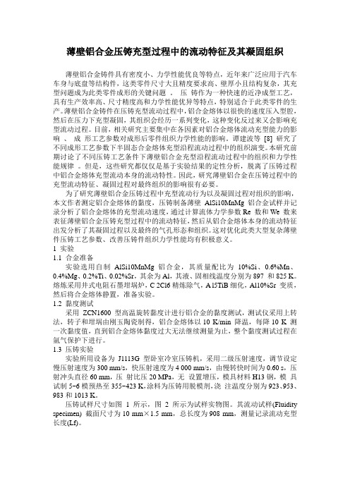
为了研究薄壁铝合金压铸过程中充型流动行为以及凝固过程对组织的影响本文作者测定铝合金熔体的黏度压铸制备薄壁alsi10mnmg铝合金试样并记录分析了铝合金熔体的充型流动速度通过计算流体力学参数re数和we数来表征薄壁铝合金压铸充型过程中的流动特征然后从铝合金熔体本身的流动特征出发分析了其凝固过程以及最终的气孔形态和组织
基金项目:国家“十二五”科技支撑计划资助项目(2011BAG03B02);国家自然科学基金面上项目(51075132);国际科技合作项目(2010DFB70180) 收稿日期:2013-02-22;修订日期:2013-05-20 通信作者:李落星,教授,博士;电话:0731-88821950;E-mail:luoxing_li@
[8] [4−5]
一次黏度值,直到铝合金熔体黏度过大无法继续测量 为止,整个黏度测试过程在氩气保护下进行。 1.3 压铸实验 实验所用设备为 J1113G 型卧室冷室压铸机,采 用二级压射速度,调节设定慢压射速度为 300 mm/s, 快压射速度为 4 000 mm/s,由慢转快时间为 0.60 s, 压射冲头直径 60 mm, 压射比压 20 MPa, 无设置增压, 模具材料 H13 钢, 模具试制 5~6 模预热至 355~423 K, 涂料为压铸用脱模剂, 浇注温度分别为 923、 953、 983 和 1013 K。 压铸试样尺寸如图 1 所示,图 2 所示为试样实 物 图 。 其 流 动 试 样 (Fluidity specimen) 截 面 尺 寸 为 10 mm×1.5 mm,总长度为 908 mm,测量记录流动充 型长度(Lf)。
薄壁铝合金压铸充型过程中的流动特征及其凝固组织
薄壁铝合金压铸充型过程中的流动特征及其凝固组织薄壁铝合金铸件具有密度小、力学性能优良等特点,近年来广泛应用于汽车车身与底盘等结构件,这类零件尺寸大且精度要求高、壁厚小且结构复杂,其充型问题成为此类零件成形的关键问题。
压铸作为一种快速的近净成型工艺,具有生产效率高、尺寸精度高和力学性能优异等特点,特别适合于此类零件的生产。
薄壁铝合金铸件在压铸充型流动过程中,铝合金熔体以很快的速度压入型腔,然后在压力下充型凝固,其组织会经历一系列变化,这种变化反过来又会影响充型流动过程。
目前,相关研究主要集中在各因素对铝合金熔体流动充型能力的影响、成形工艺参数对成形后零件组织力学性能的影响。
谭建波等[8] 研究了不同成形工艺参数下半固态合金熔体充型沿程流动过程中的组织演变。
本研究前期讨论了不同压铸工艺条件下薄壁铝合金充型沿程流动过程中的组织和力学性能规律。
但是,这些研究都仅仅是基于实验结果的定性分析,脱离了压铸过程中铝合金熔体充型流动本身的流动特性。
因此,研究薄壁铝合金在压铸过程中的充型流动特征、凝固过程对最终组织的影响很有必要。
为了研究薄壁铝合金压铸过程中充型流动行为以及凝固过程对组织的影响,本文作者测定铝合金熔体的黏度,压铸制备薄壁AlSi10MnMg 铝合金试样并记录分析了铝合金熔体的充型流动速度,通过计算流体力学参数Re 数和We 数来表征薄壁铝合金压铸充型过程中的流动特征,然后从铝合金熔体本身的流动特征出发分析了其凝固过程以及最终的气孔形态和组织。
这对优化此类大型复杂薄壁件压铸工艺参数、改善压铸件组织力学性能均有积极意义。
1 实验1.1 合金准备实验选用自制AlSi10MnMg 铝合金,其质量配比为10%Si、0.6%Mn、0.4%Mg、0.2%Ti、0.02%Sr,其余为Al,其液、固相线温度分别为897 和825 K。
熔炼采用井式电阻石墨坩埚炉,C 2Cl6精炼除气,A l5TiB细化,Al10%Sr 变质,然后将合金熔体静置,准备实验。
alsi10mnmg铝合金成分

alsi10mnmg铝合金成分
ALS10MNmg是一种常见的铝合金材料,它由铝、硅、镁和锰等元素组成。
铝合金具有较高的强度、优良的导热性和良好的耐腐蚀性,因此在工业和航空航天等领域得到广泛应用。
铝是ALS10MNmg合金的主要成分,它具有轻质、导热性好和良好的可塑性等特点。
与钢相比,铝的密度只有钢的三分之一左右,因此铝合金制品相对较轻。
这使得铝合金在航空航天和汽车制造等领域得到广泛应用,可以降低整个结构的重量,提高燃油效率和运载能力。
硅是ALS10MNmg合金的另一个重要成分,它可以提高铝合金的强度和硬度。
硅的添加可以形成硅铝化合物,使合金的晶粒细化,提高抗拉强度和硬度。
同时,硅还可以提高铝合金的耐磨性和耐蚀性,使其在恶劣环境下具有较好的耐久性。
镁是ALS10MNmg合金的另一个关键成分,它可以提高铝合金的强度和耐腐蚀性。
镁的添加可以形成镁铝化合物,使合金的晶粒细化,提高抗拉强度和硬度。
此外,镁还可以提高合金的耐腐蚀性,使其在潮湿环境和腐蚀介质中具有较好的耐蚀性。
锰是ALS10MNmg合金的另一个重要成分,它可以提高铝合金的强度和韧性。
锰的添加可以形成锰铝化合物,使合金的晶粒细化,提高抗拉强度和冲击韧性。
此外,锰还可以改善铝合金的机械加工
性能,使其更容易加工成型。
ALS10MNmg铝合金的成分主要包括铝、硅、镁和锰等元素。
铝合金具有较高的强度、优良的导热性和良好的耐腐蚀性,广泛应用于工业和航空航天等领域。
铝合金的优点在于轻质、可塑性好和耐久性强,可以满足不同领域的需求。
随着科学技术的不断发展,铝合金的应用前景将更加广阔。
alsi10mnmg导热系数

alsi10mnmg导热系数
(原创实用版)
目录
1.介绍 ALSI10MnMg 材料的特性
2.阐述 ALSI10MnMg 的导热性能
3.分析影响 ALSI10MnMg 导热系数的因素
4.总结 ALSI10MnMg 的导热性能及应用前景
正文
ALSI10MnMg(铝硅锰镁合金)是一种高性能的导热材料,它具有优良的导热性能、良好的耐腐蚀性和较低的热膨胀系数,因此在众多领域都有广泛的应用。
例如,在电子器件、散热器、汽车发动机等领域都可见到ALSI10MnMg 的身影。
ALSI10MnMg 的导热性能是其最为突出的特点之一。
导热系数是衡量材料导热性能的重要指标,它反映了材料单位面积上热量传递的速度。
ALSI10MnMg 的导热系数非常高,这意味着它能在短时间内将大量的热量传递出去,保证设备的正常运行。
然而,ALSI10MnMg 的导热系数并非固定不变,它会受到一些因素的影响。
首先,材料的成分对其导热系数有重要影响。
ALSI10MnMg 中的硅、锰、镁等元素含量的改变都可能导致导热系数的波动。
其次,材料的结构也会对导热系数产生影响。
例如,材料的晶粒尺寸、排列方式等都可能改变导热性能。
总的来说,ALSI10MnMg 是一种具有高导热性能的优秀材料。
对其导热系数的研究不仅有助于我们更好地理解 ALSI10MnMg 的性质,也有助于优化材料的制备工艺,提高其在各个领域的应用性能。
第1页共1页。
AlSi10MnMg在汽车车身轻量化中的应用

AlSi10MnMg在汽车车身轻量化中的应用
杨鸿智;尹小文;苏彦芳;王烁;于美娟
【期刊名称】《汽车实用技术》
【年(卷),期】2024(49)1
【摘要】汽车车身轻量化技术是目前最核心、最关键的轻量化路径方案,包括结构轻量化、材料轻量化和工艺轻量化三大类技术,而AlSi10MnMg铝合金是材料轻量化中的重要应用方向,由于其可以通过不同的热处理得到不同范围的机械性能和极为优异的铸造性能,成为了在汽车结构件上使用最为普遍的高强韧压铸合金。
文章详细介绍了AlSi10MnMg铝合金材料及其性能,结果表明,该铝合金的T5/T7两种热处理状态,T5态适用于实心件,如安装板;T7态适用于薄壁件,最为典型的应用为前减震器塔、后减震器塔和后纵梁。
最后以前减震器塔为例进行了外形、制造工艺和热处理制度方面的设计,可为其他车型前减震器塔的设计开发提供参考。
【总页数】5页(P167-171)
【作者】杨鸿智;尹小文;苏彦芳;王烁;于美娟
【作者单位】北京汽车研究总院有限公司;北京新能源汽车股份有限公司
【正文语种】中文
【中图分类】U465;U466
【相关文献】
1.汽车轻量化——汽车铝板在白车身和覆盖件减重中的应用
2.车身轻量化系数在重型载货汽车车身开发中的应用
3.分论坛IV-轻量化及车身材料——铝合金在汽车
轻量化应用中的最新突破4.复合结构材料与塑料在汽车车身轻量化设计中的应用5.铝-钢车身与物流铝箱成汽车轻量化主流——2021年中国乘用车铝车身与物流车铝车厢专题研讨会在沪召开
因版权原因,仅展示原文概要,查看原文内容请购买。
- 1、下载文档前请自行甄别文档内容的完整性,平台不提供额外的编辑、内容补充、找答案等附加服务。
- 2、"仅部分预览"的文档,不可在线预览部分如存在完整性等问题,可反馈申请退款(可完整预览的文档不适用该条件!)。
- 3、如文档侵犯您的权益,请联系客服反馈,我们会尽快为您处理(人工客服工作时间:9:00-18:30)。
AlSi10MnMg薄壁铝合金件压铸流动行为及其组织力学性能
薄壁铝合金铸件因具有良好的轻量化效果和优异的力学性能,在汽车车身、底盘类结构件上有广泛的应用前景。
压铸作为一种快速的近净成型工艺,特别适合此类零件的集成化设计和整体成型。
然而,薄壁铝合金铸件的压铸生产存在成型困难和力学性能不稳定等问题。
因此,对其压铸充型过程中的流动行为及其组织和力学性能展开研究,可以为此类薄壁铸件压铸成型工艺的制定和优化提供理论支持和指导。
本文以AlSi10MnMg合金为研究对象,建立了薄壁铝合金件压铸数值仿真模型,结合压铸实验结果研究其充型流动行为和组织力学性能规律。
首先,采用旋转粘度计测定该合金的粘度并讨论其特征,通过实验求解压铸铸件/铸型界面换热系数,再将粘度和界面换热系数应用于仿真并和实验结果对比,验证所建立的数值仿真模型的有效性。
然后,通过实验计算压铸过程中的流体力学参数,结合仿真对充型流动特征进行讨论,并建立薄壁铝合金件压铸充型金属液填充模型。
最后,结合仿真讨论流动试样入口处和沿程的组织力学性能,建立薄壁铝合金件压铸沿程气孔分布模型,并将建立的数值仿真模型成功应用于薄壁铝合金电机盖的工艺优化。
得到的主要结论如下:铸造过程中铝合金熔体表现非牛顿流体特性,需采用旋转粘度计测定其粘度;AlSi10MnMg合金在降温过程中其熔体内部结构会发生
一系列变化,导致其粘度变化可以分为四个阶段,各阶段粘度随温度变化的规律不同。
根据薄壁铝合金件压铸充型速度快和时间短的特点,将充型过程分为液相充型阶段和液/固两相充型阶段,分别求解和讨论了各阶段的铸件/铸型界面换热系数。
然后在此基础上建立了薄壁铝合金件压铸数值仿真模型。
薄壁铝合金流动试样压铸充型临界长度在浇注温度为923~1013K范围内达510~810mm。
通过实验计算发现其压铸充型过程中铝合金熔体流动的Re<2000、
We>>60,结合紊流仿真结果推测铝合金熔体以层流、充型前端液面自由表面破碎成细小液滴的喷射形式高速填充流动试样型腔,由此建立了一种针对薄壁铝合金件压铸充型金属液填充模型,表明在其压铸充型过程中喷射状态和“全壁厚”状态一直存在且保持至充型结束。
结合仿真和实验观测发现,薄壁铝合金压铸流动试样沿程气孔先减少后增加,建立的沿程气孔分布模型将气孔沿程分为四个部分。
沿程密度主要受流动性影响。
初生α-Al相组织随浇注温度的升高晶粒越来越细,分布也更均匀,但沿程变化不大。
入口处力学性能随浇注温度的升高先增加后减小。
浇注温度较低时,沿程力学性能下降明显,主要受气孔影响;浇注温度较高时,力学性能沿程基本保持不变,波动较小,沿程力学性能较稳定,压力对力学性能作用显著。