第4章 自动运行工作 enc68
ACS6000中文手册

ACS 6000 用户手册
3BHS...................................................................................................................................................... 5 简介 ........................................................................................................................................................ 8
ACS 6000 中压变频器
(3至27兆伏安)
用户手册
文件编号.: 3BHS212794 ZAB E01 Rev. - 发布时期: 06-03-2005
© ABB 保留所有权利。
ABB 公司保留对本手册的解释权,未得到我们的许可任何人不得向第三方 提供手册中的信息,用户如果发现本手册中的错误请向ABB公司反映。 本手册中的信息如果和目前最新产品有不同之处请参照产品随机说明。
联络信息......................................................................................................................................... 8 第 1 章 - 安全须知 ................................................................................................................................ 9
埃夫特 ER 系列机器人 操作手册说明书

2 手册使用 ........................................................................................................................................8
1.3 各工作过程中的安全注意事项 ...............................................................................................12
第 2 章 欢迎使用埃夫特机器人 ........................................................................................................... 20
相关活动的人员,在学习完毕埃夫特公司准备的培训课程前,请勿赋予其
对机器人的操作使用权限。
版本ቤተ መጻሕፍቲ ባይዱ:V 3.3.0.1
1
目录
概 述 ......................................................................................................................................................... 8
贝利摩(Belimo)SF24G-SR-S2-L模块调节旋转驱动器说明书
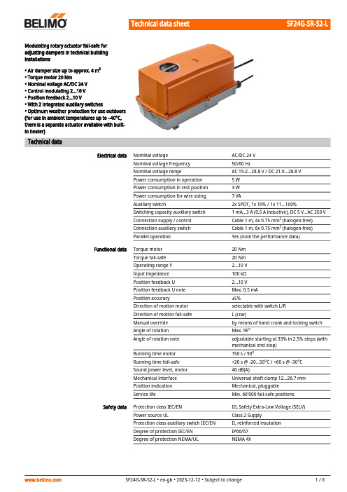
SF24G-SR-S2-L Modulating rotary actuator fail-safe foradjusting dampers in technical buildinginstallations• Air damper size up to approx. 4 m²• Torque motor 20 Nm• Nominal voltage AC/DC 24 V• Control modulating 2...10 V• Position feedback 2...10 V• With 2 integrated auxiliary switches• Optimum weather protection for use outdoors(for use in ambient temperatures up to –40°C,there is a separate actuator available with built-in heater)Technical dataElectrical data Nominal voltage AC/DC 24 VNominal voltage frequency50/60 HzNominal voltage range AC 19.2...28.8 V / DC 21.6...28.8 VPower consumption in operation 5 WPower consumption in rest position 3 WPower consumption for wire sizing7 VAAuxiliary switch2x SPDT, 1x 10% / 1x 11...100%Switching capacity auxiliary switch 1 mA...3 A (0.5 A inductive), DC 5 V...AC 250 VConnection supply / control Cable 1 m, 4x 0.75 mm² (halogen-free)Connection auxiliary switch Cable 1 m, 6x 0.75 mm² (halogen-free)Parallel operation Yes (note the performance data)Functional data Torque motor20 NmTorque fail-safe20 NmOperating range Y 2...10 VInput impedance100 kΩPosition feedback U 2...10 VPosition feedback U note Max. 0.5 mAPosition accuracy±5%Direction of motion motor selectable with switch L/RDirection of motion fail-safe L (ccw)Manual override by means of hand crank and locking switchAngle of rotation Max. 95°Angle of rotation note adjustable starting at 33% in 2.5% steps (withmechanical end stop)Running time motor150 s / 90°Running time fail-safe<20 s @ -20...50°C / <60 s @ -30°CSound power level, motor40 dB(A)Mechanical interface Universal shaft clamp 12...26.7 mmPosition indication Mechanical, pluggableService life Min. 60'000 fail-safe positionsSafety data Protection class IEC/EN III, Safety Extra-Low Voltage (SELV)Power source UL Class 2 SupplyProtection class auxiliary switch IEC/EN II, reinforced insulationDegree of protection IEC/EN IP66/67Degree of protection NEMA/UL NEMA 4XSF24G-SR-S2-LSafety dataEnclosure UL Enclosure Type 4XEMCCE according to 2014/30/EU Low voltage directive CE according to 2014/35/EUCertification IEC/EN IEC/EN 60730-1 and IEC/EN 60730-2-14UL ApprovalcULus according to UL60730-1A, UL60730-2-14 and CAN/CSA E60730-1The UL marking on the actuator depends on the production site, the device is UL-compliant in any case Type of actionType 1.AA.B Rated impulse voltage supply / control 0.8 kV Rated impulse voltage auxiliary switch 2.5 kV Pollution degree 4Ambient humidity Max. 100% RH Ambient temperature -30...50°C [-22...122°F]Ambient temperature note -40...50°C for actuator with integrated heating Storage temperature -40...80°C [-40...176°F]Servicingmaintenance-free WeightWeight 4.5 kgTechnical data••••••••••••••Safety notesThis device has been designed for use in stationary heating, ventilation and air-conditioning systems and must not be used outside the specified field of application, especially in aircraft or in any other airborne means of transport.Only authorised specialists may carry out installation. All applicable legal or institutional installation regulations must be complied with during installation.Junction boxes must at least correspond with enclosure IP degree of protection!The cover of the protective housing may be opened for adjustment and servicing. When it is closed afterwards, the housing must seal tight (see installation instructions).The device may only be opened at the manufacturer's site. It does not contain any parts that can be replaced or repaired by the user.The cables must not be removed from the device installed in the interior.To calculate the torque required, the specifications supplied by the damper manufacturers concerning the cross-section and the design, as well as the installation situation and the ventilation conditions must be observed.The two switches integrated in the actuator are to be operated either on power supply voltage or at safety extra-low voltage. The combination power supply voltage/safety extra-low voltage is not permitted.The device contains electrical and electronic components and must not be disposed of as household refuse. All locally valid regulations and requirements must be observed.The device is not designed for applications where chemical influences (gases, fluids) are present or for utilisation in corrosive environments in general.The actuator may not be used in plenary applications (e.g. suspended ceilings or raised floors).The materials used may be subject to external influences (temperature, pressure,construction fastening, effect of chemical substances, etc.), which cannot be simulated in laboratory tests or field trials. In case of doubt, we definitely recommend that you carry out a test. This information does not imply any legal entitlement. Belimo will not be held liable and will provide no warranty.Flexible metallic cable conduits or threaded cable conduits of equal value are to be used for UL (NEMA) Type 4X applications.When used under high UV loads, e.g. extreme sunlight, the use of flexible metallic or equivalent cable conduits is recommended.SF24G-SR-S2-LProduct featuresFields of application The actuator is particularly suitable for utilisation in outdoor applications and is protectedagainst the following weather conditions:- UV radiation- Rain / Snow- Dirt / Dust- Air humidity- Alternating climate / frequent and severe temperature fluctuations (Recommendation: usethe actuator with integrated factory-installed heating which can be ordered separately toprevent internal condensation)Operating mode The actuator is connected with a standard control signal of 0...10 V and moves the damper tothe operating position at the same time as tensioning the return spring. The damper is turnedback to the fail-safe position by spring force when the supply voltage is interrupted.Simple direct mounting Simple direct mounting on the damper shaft with a universal shaft clamp, supplied with ananti-rotation device to prevent the actuator from rotating.Manual override By using the hand crank the damper can be actuated manually and engaged with the lockingswitch at any position. Unlocking is carried out manually or automatically by applying theoperating voltage.The housing cover must be removed for manual override.Adjustable angle of rotation Adjustable angle of rotation with mechanical end stop. The housing cover must be removedto set the angle of rotation.High functional reliability The actuator is overload protected, requires no limit switches and automatically stops whenthe end stop is reached.Flexible signalling The actuator has one auxiliary switch with a fixed setting and one adjustable auxiliary switch.They permit a 10% or 11...100% angle of rotation to be signaled.AccessoriesElectrical accessories Description TypeSignal converter voltage/current 100 kΩ 4...20 mA, Supply AC/DC 24 V Z-UICPositioner for wall mounting SGA24Positioner for built-in mounting SGE24Positioner for front-panel mounting SGF24Positioner for wall mounting CRP24-B1 Mechanical accessories Description TypeCable gland for cable diameter ø4...10 mm Z-KB-PG11 Options ex works only Description TypeHeater, with adjustable thermostat HT24-FGHeater, with mechanical humidistat HH24-FG Electrical installationSupply from isolating transformer.Parallel connection of other actuators possible. Observe the performance data.SF24G-SR-S2-L Wire colours:1 = black2 = red3 = white5 = orangeS1 = violetS2 = redS3 = whiteS4 = orangeS5 = pinkS6 = greyWiring diagramsAC/DC 24 V, modulatingAuxiliary switch Electrical installationSF24G-SR-S2-LOperating controls and indicatorsAuxiliary switch settingsNote: Perform settings on the actuator only in deenergised state.For the auxiliary switch position settings, carry out points 1 to 7 successively.1Manual overrideTurn the hand crank until the desired switching position is set.2Shaft clampEdge line A displays the desired switching position of the actuator on thescale.3Fasten the locking deviceTurn the locking switch to the …Locked padlock“ symbol.4Auxiliary switchTurn rotary knob until the notch points to the arrow symbol.5Unlock the locking deviceTurn the locking switch to the …Unlocked padlock“ symbol or unlock withthe hand crank.6CableConnect continuity tester to S4 + S5 or to S4 + S6.7Manual overrideTurn the hand crank until the desired switching position is set and checkwhether the continuity tester shows the switching point.SF24G-SR-S2-LDimensionsSpindle length-16...105 (ø12...19)16...45 (ø19...26.7)Clamping range。
穿越操作系统迷雾:从零实现操作系统_随笔

《穿越操作系统迷雾:从零实现操作系统》读书记录目录一、内容概览 (2)二、第一章 (3)1. 操作系统定义及功能 (4)2. 操作系统发展历史 (5)3. 操作系统分类 (7)三、第二章 (8)1. 系统调用与API (9)2. 进程管理 (10)3. 内存管理 (11)4. 文件系统管理 (12)四、第三章 (13)1. 构建环境搭建与工具选择 (15)2. 系统框架设计与实现 (16)3. 系统核心功能实现 (17)五、第四章 (19)1. 进程调度与CPU管理 (20)2. 文件系统设计与实现 (21)3. 存储管理策略解析 (21)4. 中断与异常处理机制 (22)六、第五章 (24)1. 操作系统性能评估指标与方法 (25)2. 系统性能优化策略与技术手段 (27)3. 操作系统安全与稳定性保障措施 (29)七、第六章 (30)一、内容概览《穿越操作系统迷雾:从零实现操作系统》是一本关于操作系统原理和技术的书籍,作者通过深入浅出的方式,带领读者领略操作系统的奥妙。
本书共分为五个部分,分别是:基本概念与设计原理、进程管理、内存管理、文件系统和设备驱动。
第一部分主要介绍了操作系统的基本概念和设计原理,包括操作系统的作用、分类、发展历程以及常见的操作系统内核结构。
通过对这些概念的讲解,读者可以对操作系统有一个整体的认识。
第二部分主要讲述了进程管理,包括进程的创建、调度、同步与通信等。
作者通过实例和图示,详细解释了进程管理的核心原理和技术,帮助读者理解进程管理的实现方式。
第三部分主要介绍了内存管理,包括内存分配、虚拟内存、页面置换算法等内容。
通过对内存管理的剖析,读者可以掌握操作系统在内存管理方面的关键技术和策略。
第四部分主要讨论了文件系统,包括文件操作、目录结构、磁盘调度等内容。
作者通过实际案例和理论分析,帮助读者理解文件系统的工作原理和实现方法。
第五部分主要介绍了设备驱动,包括设备驱动的基本概念、接口定义、驱动程序编写等内容。
福泽CELSIUS H780移动工作站数据册说明书

Data SheetFujitsu CELSIUS H780Mobility. Security. Virtual Reality.Meet the FUJITSU CELSIUS H780, the world’s first 39.6 cm (15.6-inch) mobile workstation combining ultimate security with future technologies. While creatives and innovators are working onincreasingly huge datasets, this machine will not weigh them down when showcasing designs in virtual reality at events or at the customer site.Need For SpeedWhen true workstation performance meets the elegant style of a laptopChoose between Intel® Core™ processors or powerful Intel® Xeon® processor E-2100M family supporting ECC memory Windows 10 Pro supportFull HD LED anti-glare displays (incl. touch option) Up to 64 GB DDR4 2400 MHz memory (ECC optional)Dual M.2 PCIe-SSD NVMe technology supports quick loading of core applicationsFull connectivity and worry-free docking experienceNo compromise in terms of connectivity, regardless of whether you are away, in a meeting or at your deskChoice of port replicators with mechanical or Thunderbolt™ 3 connectorMechanical port replicator: Offering charging capabilities for the mobile workstation.Thunderbolt™ 3 port replicator: 2x USB Type-C™ connector offering speed up to 40Gbps, and charging capabilities of to 15 W for e.g. mobile phone or power bank. The mobile workstation requires a power supply with at least 230 W.Full monitor connectivity support: 1x VGA and 1x HDMI.Mobility Meets SecurityData security and peace of mindOptional PalmSecure™, a leading-edge highly secure authentication system using biometric technology that authenticates users through vein pattern recognition Integrated SmartCard readerTPM 2.0 and Advanced Theft ProtectionWe are (VR) readyArchitects, engineers and designers can now showcase their work in a real-time, fully immersive VR environmentPowered by the NVIDIA® Quadro® P3200 VR-ready graphics card Ideal for mobile VR showcases at the customer site or at an eventEasy connectivity of the head-mount display to the HDMI portComponentsMemory modules8 GB (1 module(s) 8 GB) DDR4, 2,400 MT/s, PC4-2400, SO DIMM16 GB (2 module(s) 8 GB) DDR4, 2,400 MT/s, PC4-2400, SO DIMM32 GB (2 module(s) 16 GB) DDR4, 2,400 MT/s, PC4-2400, SO DIMMHard disk drives (internal)SSD SATA III, 512 GB, M.2 module, SEDSSD SATA III, 256 GB, M.2 module, SEDPCIe-SSD, NVMe, 512 GB Highend, M.2 module, SEDPCIe-SSD, NVMe, 512 GB Highend, M.2 modulePCIe-SSD, NVMe, 256 GB Highend, M.2 moduleHDD SATA III, 5,400 rpm, 1000 GBHDD SATA III, 5,400 rpm, 500 GBInterface add on cards/components(optional)3G/4G (optional)Sierra Wireless EM7455 (Cat. 6)Base unitPort Replicator interfaces (optional)Notes Thunderbolt Port Replicator Mechanical Port ReplicatorDC-in1x1xPower on switch---1Audio: line-in / microphone1x1xAudio: line-out / headphone1x1xUSB 2.0 total2x---USB 3.1 Gen1 (USB 3.0) total2x6x (4x USB Type-A, 2x USB Type-C) DisplayPort2x (1x through from TBT3 TypeC, 1x via internal DP-Splitter), resolution up to 3840 x 2160; no DP++ support2x, resolution up to 3840 x 2160, 16M colors, 60HzVGA1x (via TBT3 internal DP-splitter) resolution up to 1920 x1200, 16M colors, 60Hz1x resolution up to 1920 x 1200, 16M colors, 60HzDVI1x (via TBT3 internal DP-splitter) resolution up to 1920 x1200, 16M colors, 60Hz1x resolution up to 1920 x 1200, 16M colors, 60HzInterface Notes at least 230W power supply required for mobileworkstation DisplayPort next to USB and HDMI at Mobile WORKSTATION sharing the same channel (only one connection at a time possible); Dock DP2, CRT, DVI ports will share the same DP port bandwidth with VM3332ProductCompliance link https:///sites/certificatesWarrantyWarranty period 3 years (depending on country)Warranty type Bring-in Service / Collect & Return Service (depending on country) Product Support - the perfect extensionRecommended Service9x5, Onsite Response Time: Next Business DaySpare Parts availability at least 5 years after shipment, for details see https:///Recommended AccessoriesCELSIUS® H780 Port ReplicatorKitFlexibility, expandability, desktop replacement, investment protection – to name just a few benefits of Fujitsu’s docking options.Order Code: S26391-F2249-L300Privacy FiltersTo use privacy filters is a must in times of increased safety requirements. Fujitsu’s Privacy Filters block unauthorized views on your screen while you are sitting in an external meeting or working in a train. The front view remains clear for the user’s eyes only. The filters are easy to attach and what’s more: They also protect your screen from small scratches and damages.Order Code:S26391-F6098-L215Prestige Case 15 (2021)The Prestige Case 15 protects notebooks with up to 15.6-inch screens. The front compartment provides space for your power cord and office supplies.The large compartment is devided for your notebook and a tablet.Order Code:S26391-F1120-L60Prestige Trolley 17The Fujitsu Prestige Trolley 17 protects and transports notebooks withup to 17 inch screens, along with clothes and toiletries. It is the perfectcompanion in a city environment or for overnight stays with four spacious compartments. Smooth running wheels and a telescopic handle ensure convenience, while the central section protects your notebook with shock-absorbing foam.Order Code: S26391-F1194-L130Display P27-8 TS UHDThe FUJITSU Display P27-8 TS UHD is perfect for multi-monitor usescenarios with its 3840 x 2160 Ultra HD resolution and the thin bezelhousing. The monitor has a 78°/178° wide viewing angle and a 100% sRGB color space to deliver you a consistent high picture quality. Features like ECO function, the DisplayView™ IT Suite manageability software as a range of connectivity options meet the requirements of medium- and large-sized businesses.Order Code: S26361-K1610-V160ContactAddress: x-xx-x, street, city, state, ZIP code, country Phone: xx-xxxx-xxxx Fax : xx-xxxx-xxxxEmail:********************.com Website: /[country]2023-11-27 CE-ENdelivery subject to availability. Any liability that the data and illustrations are complete, actual or correct is excluded. Designations may be trademarks and/or copyrights of the respective manufacturer, the use of which by third parties for their own purposes may infringe the rights of such ownerMore informationAll rights reserved, including intellectual property rights. Changes to technical data reserved. Delivery subject to availability. Any liability that the data and illustrations are complete, actual or correct is excluded.Designations may be trademarks and/or copyrights of the respective manufacturer, the use of which by third parties for their own purposes may infringe the rights of such owner.For further information see /terms_of_use.html Copyright © Fujitsu Technology Solutions。
PLC在矿井提升机变频调速中的应用毕业论文(含开题报告和中期答辩)

本科毕业设计(论文)PLC在矿井提升机变频调速中的应用2011年6月本科毕业设计(论文)PLC在矿井提升机变频调速中的应用摘要摘要矿井提升机是矿山最重要的设备,肩负着矿石、物料、人员等的运输责任。
传统的矿井提升机控制系统主要采用继电器-接触器进行控制,这类提升机通常在电动机转子回路中串接附加电阻进行启动和调速。
这种控制系统存在可靠性差、操作复杂、故障率高、电能浪费大、效率低等缺点。
针对这种情况采用PLC与变频器相结合的控制方案对原有电控系统进行改造,提高整个电控系统安全可靠性、控制精度及调速性能。
因此,对矿井提升机控制系统进行研究具有现实意义,也是国内外相关行业专家学者的一个热门研究课题。
本文把可编程序控制器和变频器应用于提升机控制系统上,并在可行性方面进行了较深入的研究。
事实表明,采用该控制系统,使提升机工作可靠,使用方便,同时具有动态显示的功能,节能效果明显。
关键词:矿井提升机;变频调速;矢量控制;PLC;AbstractThe shaft hoist is the foremost equipment of mines,it is widely used to transport the materials,staff and equipment. The traditional shaft hoist control system is always controlled by the relay-contactor,and adopts the methods of connect series additional resistant in rotors winding loop to start and adjust speed. The system has many disadvantages such as bad reliability,complicated operation,high fault rate,large energy –wasting and low efficiency.According to this kind of condition, we adopt PLC and Transducer to reform for original control system, so as to raise the safety, reliability, speed regulation performance of the whole electric controlled system. So, carrying on the research on the shaft hoist control system has realistic meanings,and it is a subject for research by relevant experts and scholars,both at home and abroad.To these questions existing in the shaft hoist contro1 system,the paper applied PLC(Programmable Logic Controller)and frequency converter to the system, and carried on deeper research in feasibility. The fact indicates,adopting control system,the shaft hoist works reliably,easy to use,energy-saving well,and have dynamical shown function.Keywords:Shaft hoist;Frequency conversion;Vector control;PLC目录摘要 (I)Abstract ................................................................................................................ I I 第1章绪论.. (1)1.1课题概述 (1)1.2课题来源 (1)1.3国内外提升机研究状况 (2)1.4本文内容及研究意义 (5)1.4.1研究内容 (5)1.4.2研究意义 (6)第2章提升机的工况分析 (9)2.1提升系统简介 (9)2.2提升机电动机运行方式 (9)2.3提升机的速度图和力图 (10)2.3.1提升机的速度图 (10)2.3.2力图 (11)2.4矿井提升机对电气控制系统的要求 (12)本章小结 (15)第3章可编程控制器简介 (17)3.1PLC的基本特点 (17)3.2PLC的基本结构 (19)3.3PLC的工作原理 (20)3.4PLC的分类 (21)3.5PLC编程 (23)3.5.1PLC执行用户程序的过程 (23)3.5.2梯形图的表示 (24)3.5.3梯形图的编程规则 (25)本章小结 (25)第4章:矢量控制变频调速 (27)4.1变频调速的发展及在提升机系统中的应用 (27)4.2变频调速基本原理 (29)4.3变频调速控制方式分类 (32)4.4变频器按中间直流环节方式分类 (33)4.5变频调速技术的发展现状 (34)本章小结 (35)第5章总体设计方案 (37)5.1系统控制要求 (37)5.2选择机型 (37)5.3控制系统的I/0点 (38)5.4系统控制结构 (38)5.4.1系统主电路图 (38)5.4.2系统控制电路图 (39)5.4.3系统外围接线图 (39)5.5设计步骤 (39)5.6系统流程框图 (40)5.7硬件部分设计 (41)5.7.1输出规格 (41)5.7.2标度变换 (41)5.7.3变频器参数设置表 (41)5.8软件部分设计 (42)5.9实验及结果 (43)5.9.1实验过程 (43)5.9.2实验现象 (43)5.9.3实验结果 (44)本章小结 (44)结论 (45)参考文献 (47)致谢 (49)附录 (51)第1章绪论第1章绪论1.1 课题概述矿井提升机是机、电、液一体化的大型机械[1],广泛用于煤炭、有色金属、黑色金属、非金属、化工等矿山的竖井、斜井,是生产运输的主要工具。
F-TM ServoDrive SIMATIC ET 200SP F-TM ServoDrive 设

SIMATICET 200SPF-TM ServoDrive 设备手册Siemens AG Division Digital Factory Postfach 48 48 90026 NÜRNBERG A5E47579551-ABⓅ 04/2020 本公司保留更改的权利Copyright © Siemens AG 2020.保留所有权利法律资讯警告提示系统为了您的人身安全以及避免财产损失,必须注意本手册中的提示。
人身安全的提示用一个警告三角表示,仅与财产损失有关的提示不带警告三角。
警告提示根据危险等级由高到低如下表示。
危险表示如果不采取相应的小心措施,将会导致死亡或者严重的人身伤害。
警告表示如果不采取相应的小心措施,可能导致死亡或者严重的人身伤害。
小心表示如果不采取相应的小心措施,可能导致轻微的人身伤害。
注意表示如果不采取相应的小心措施,可能导致财产损失。
当出现多个危险等级的情况下,每次总是使用最高等级的警告提示。
如果在某个警告提示中带有警告可能导致人身伤害的警告三角,则可能在该警告提示中另外还附带有可能导致财产损失的警告。
合格的专业人员本文件所属的产品/系统只允许由符合各项工作要求的合格人员进行操作。
其操作必须遵照各自附带的文件说明,特别是其中的安全及警告提示。
由于具备相关培训及经验,合格人员可以察觉本产品/系统的风险,并避免可能的危险。
按规定使用 Siemens 产品请注意下列说明:警告Siemens产品只允许用于目录和相关技术文件中规定的使用情况。
如果要使用其他公司的产品和组件,必须得到Siemens推荐和允许。
正确的运输、储存、组装、装配、安装、调试、操作和维护是产品安全、正常运行的前提。
必须保证允许的环境条件。
必须注意相关文件中的提示。
商标所有带有标记符号 ® 的都是 Siemens AG的注册商标。
本印刷品中的其他符号可能是一些其他商标。
若第三方出于自身目的使用这些商标,将侵害其所有者的权利。
SIMOCODE pro 电机管理系统说明说明书

2The highlights of SIMOCODE pro• E xtensive protection, monitoring and control functions, independent of the automation system • D etailed operational, service and diagnostics data – at any time or place • Safe shutdown of motors• S calable, flexible solutions for all plant configurations• V ersatile, open communication via various bus systems and protocols • I ntegration in process control systems such as SIMATIC PCS 7• Supports PROFINET system redundance and dynamic reconfigurationSIMOCODE pro offers multifunctional, solid-state full motor protection. The motormanagement system monitors, protects and controls constant-speed motors and enables the implementation of predictive maintenance. It does not wait for a prob-lem to occur before shutting down the motor, but establishes a level of transparency in advance. This avoids plant standstills and improves economic efficiency. SIMOCODE pro delivers detailed operating, service and diagnostic data from across the entire process. The engineering is simple and likewise the integration into pro-cess control systems. SIMOCODE pro communicates via PROFIBUS and PROFINET, Modbus, EtherNet / IP and OPC UA. It implements simple and economical motor management.With both the SIMOCODE pro General Performance and SIMOCODE pro High Perfor-mance device classes, we offer scalable, flexible solutions for industrial controls and plant optimization in the context of Industrie 4.0.For 30 years now, SIMOCODE pro has been controlling and moni-toring low-voltage, constant-speed motors all over the world. Wherever motors keep things running in the process industry,SIMOCODE is there. Many thousands of times over. Now even more powerful thanks to connection to the Cloud.Flexible, modular, integrated.The way modern motor management should be.3Two functionally graded device series form the core of the multifunctional SIMOCODE pro motor management sys-tem: General Performance and High Performance. The de-vices in both series incorporate all essential motor protec-tion, monitoring and control functions – including data transparency through the Cloud connection. SIMOCODE pro General Performance is your entry into modern motor management and addresses standard motor applications. SIMOCODE pro High Performance features up to five expan-sion modules and offers additional measured variables. Find out how you can take advantage of the two SIMOCODEpro device series in all areas of the process industry.SIMOCODE pro. A really strong family.SIMOCODE pro –General Performance:Ideal for the entry levelThe smart and compact motor management system for direct-on-line, reversing, and star-delta (wye-delta) starters or for controlling a motor starter protector or soft starter. The basic system includes a current measuring module and the basic unit for overload or thermis-tor motor protection, for example. Communication with the automa-tion level takes place via PROFIBUS/ PROFINET. Optional additions in-clude an operator panel and an expansion module that allows additional inputs/outputs, ground-fault detection and temperature measurement to be realized. SIMOCODE pro – High Performance:The fully professional solutionfor every motorThe SIMOCODE pro High Perfor-mance motor management systemis variable, intelligent and can beadapted individually to suit everyrequirement. The basic systemincludes a module for measuringcurrent (and optionally also volt-age), as well as a basic unit, and issuitable for removing pump block-ages, for example. Communicationwith the automation level takesplace via PROFIBUS or Modbus RTU,via Ethernet with the PROFINET orEtherNet/IP protocols, and also viaOPC UA. The optional expansionsavailable include separate current/voltage measuring modules fordry-running protection, an operatorpanel with display, a ground-faultmodule, a temperature module,standard digital modules, fail-safedigital modules and an analogmodule.SIMOCODE pro Safety:Fail-safe expansion modulesVarious modules are available forSIMOCODE pro for the extendedprotection of personnel, machinesand the environment. These guar-antee the safety-related shutdownof motors and meet all the require-ments of the standards.The advantages:• F unctional switching andfail-safe shutdown withoutmanual wiring or additionaleffort• S afety function parameterscan be flexibly configured• T ransfer of meaningful diag-nostic data to thecontrol system• L ogging of errors for detailedevaluation• Fail-safe shutdown viaPROFIsafe5S IMOCODE pro –The advantages at a glance• M inimized downtimes – with less maintenance work• E nergy and cost savings over the entire plant life cycle • S imple use • S calable solution• A choice of networked or autonomousconfigurationRemove pump blockages and increase availability.6Every water utility is familiar with the prob-lems of a blocked pump – and the possible consequences: environmental harm, damage due to flooding, and dangers to health as a result of lifting and cleaning pumps. This is compounded by the financial impact of plant downtimes. SIMOCODE pro monitors the current and active power of the pump motor – and derives the pump status from them. If a defined threshold value is exceeded, SIMOCODE pro autonomously reverses the rotational direction of the pump in order to dislodge deposits on the impeller blades, for example.Say goodbye to blocked pumps with SIMOCODE pro – the modular, com-pact motor management system that tackles the challenge by auto-matically reversing the pump. An-other benefit: SIMOCODE pro can be retrofitted in existing plants.Reliable dry-running protection is a must in many applications in the chemi-cal industry. SIMOCODE pro reliably prevents the dry running of centrifugal pumps in order to preclude hazardous situations – and completely rede-fines dry-running protection for pumps in hazardous areas with an innova-tive solution.Sensors on centrifugal pumps in hazardous areas are often prone to fault and are thus high-mainte-nance. The solution: Using active power-based dry-running detection, SIMOCODE pro monitors the active electrical power consumption of the pump motor and thus the status of the pump – without the need for additional monitoring devices or sensors to be installed. The new technology ensures reliable explosion protection in accordance with ATEX and IECEx criteria and saves costs and time for commis-sioning and maintenance.Your benefits through active power-based dry-running protection• Earlier fault detection – D irect conclusions concerning the flow rate can be drawn from the active power consumption of the pump motor – R eliable prevention of dry running of the pump and therefore less damage to the pump • Cost and time savings – N o maintenance effort due to the elimination of mechanical wear of the sensors –No additional sensor required • Reduction of hardware – N o need for additional sensors and mechanical components –Simplified engineering• Reliable monitoring of the system–Compliance with ATEX and IECEx criteria – R eliable and automatic pump shutdown in the event of inadmissible operating conditionsReliable monitoring. Dry-running protection reconceptualized.7SIMOCODE pro with OPC UABenefitsMindSphere8BenefitsSIMOCODE pro is your reliable data supplier for maximum process quality. The motor management system offers:• Data analysis and simulation • S ecure data storage and transmission • Visualization and recommendation(s)• I ncreased availability of components • Optimization of energy consumption • Maximization of process efficiency • Support of PROFINET system redundance and dynamic reconfigurationFor diagnostics and simple configuration, including in the TIA Portal: SIMOCODE ESSIMOCODE ES provides you with the software for the con-figuration, startup, operation and diagnosis of SIMOCODE pro. The software is based on the central Totally Integrated Automation Portal (TIA Portal) engineering framework, pro-viding an integrated, efficient and intuitive solution for all automation tasks. SIMOCODE ES offers you a host of advan-tages, including convenient configuration in the device view, graphical commissioning using drag and drop functions, mass engineering, presentation of signal states online, or clear measurement curves for diagnostic purposes.The convenient way to optimum process guidance: The integration of SIMOCODE pro into SIMATIC PCS 7Using standardized blocks and faceplates, SIMOCODE pro can very easily be integrated into the SIMATIC PCS 7 process con-trol system. This makes it extremely easy to integrate service and diagnostic data from the motor management system into higher-level process control systems, for example.The result: A high level of transparency throughout the plant, enabling faults to be detected at an early stage or prevented from occurring altogether. In general, the greater density of information in the control system enables you to achieve not only greater transparency, but also higher pro-cess quality.Support of redundance mechanisms and dynamic recon- figuration (device extension during ongoing operation) in-creases the plant availability.9SIMOCODE pro system overview – General PerformancePublished by Siemens AGSmart Infrastructure Electrical ProductsWerner-von-Siemens-Str. 48–50 92224 Amberg GermanyFor the U.S. published by Siemens Industry Inc.100 Technology Drive Alpharetta, GA 30005 United StatesArticle No. SIEP-B10327-00-7600 Printed in GermanyWS 09221.0 Dispo 25600SoftwareSubject to changes and errors. The information given in this document only contains generaldescriptions and/or performance features which may not always specifically reflect those described, or which may undergo modification in the course of further development of the products.The requested performance features are binding only when they are expressly agreed upon in the concluded contract.SIMOCODE is a registered trademark of Siemens AG. Any unauthorized use is prohibited. All other des-ignations in this document may represent trademarks whose use by third parties for their own purposes may violate the proprietary rights of the owner.© Siemens 2022SIMOCODE ES (TIA Portal) V18 BasicBasic functional scope including Professional Trial LicenseBoth software and documentation can be downloaded for free, see:https:///cs/ww/en/view/109811683SIMOCODE ES (TIA Portal) V18 ProfessionalFloating license for one user• L icense key on USB flash drive, SW on DVD 3ZS1322-6CC16-0YA5 • L icense key and software download 3ZS1322-6CE16-0YB5 Upgrade for SIMOCODE ES 2007 Premium 3ZS1322-6CC16-0YE5Software Update Service3ZS1322-6CC00-0YL5SIMOCODE pro block library for SIMATIC PCS 7 Version V9.1 with Advanced Process Library (APL)Engineering software V9.1 (OSD)3ZS1632-1XE04-0YA0Runtime license V9.1 (OSD)3ZS1632-2XE04-0YB0Upgrade for PCS 7 block library SIMOCODE pro V8 or V9.0 (OSD)3ZS1632-1XE04-0YE0Upgrade for PCS 7 block library SIMOCODE pro V7 (without APL)3ZS1632-1XE04-0YF0SIMOCODE pro block library for SIMATIC PCS 7 Version V9.0 with Advanced Process Library (APL)Engineering software V9.0 (OSD)3ZS1632-1XE03-0YA0Runtime license V9.0 (OSD)3ZS1632-2XE03-0YB0Upgrade for PCS 7 block library SIMOCODE pro V83ZS1632-1XX03-0YE0SIMOCODE pro block library for SIMATIC PCS 7 without Advanced Process Library (APL)。
Geehy APM32F072x8 xB 32 位微控制器数据手册说明书
数据手册DatasheetAPM32F072x8/xB基于Arm® Cortex®-M0+内核的32位微控制器版本:V1.0产品特性⏹内核32位Arm®w Cortex®-M0+内核最高48MHz工作频率⏹片上存储器Flash:64~128KBSRAM:16KB⏹时钟4~32MHz晶体振荡器带校准的32KHzwRTC振荡器内部8MHzwRC振荡器内部48MHz自动校正RC振荡器内部40KHzwRC振荡器PLL支持2~16倍频⏹复位、电源管理上电/掉电复位(POR/PDR)可编程电压调节器数字供电电压:V DD=2.0~3.6V模拟供电电压:V DDA=V DD~3.6V部分I/O供电电压:V DDIO2=1.65~3.6V支持外部电池V BAT为RTC及备份寄存器供电:V BAT=1.65~3.6V ⏹低功耗模式睡眠、停机、待机模式⏹串行线调试(SWD)⏹I/O最多87个I/Os所有I/O可映射到外部中断向量最多68个容忍5V输入的I/O,19个I/O由V DDIO2供电⏹通信接口2个I2C接口(1Mbit/s),全部支持SMBus/PMBus和唤醒。
4个USART接口,全部支持主同步SPI和调制解调控制,其中2个支持ISO7816、LIN、IrDA接口、自动波特率检测和唤醒。
2个SPI接口(18Mbit/s),全部支持I2S接口复用1个CAN接口1个全速USB2.0接口,无需外挂晶振,支持BCD和LPMHDMIwCEC⏹模拟外设1个12位ADC,最多支持16个外部通道,转换范围0~3.6V,独立模拟电源:V DDA=2.4~3.6V1个双通道、12位DAC2个可编程模拟比较器最多24个电容传感通道,可用于接近、触键、线性或旋转传感器⏹定时器1个可提供最多7通道PWM输出的16位的高级控制定时器,支持死区生成和刹车输入功能1个32位和5个16位通用定时器,每个定时器有多达4个独立通道用于输入捕获/输出比较、PWM互补,用于红外控制解码或DAC控制。
OMRON NX701-1720系统自动化控制器说明书
NX701-1720Sysmac NX7 CPU with Database Connectivity, 80MB memory, built-in EtherCAT (256 servo axes, in total 512 EtherCATnodes) and 2 EtherNet/IP portsIndustrial AutomationController functionality DB connection, Motion control, OPC-UA, Sequence control Primary task cycle time0.125 msProgram memory80 MBVariables memory260 MBMax. number of synchronous axes256Max. number of axes (incl. virtual)256Communication port(s)EtherCAT Master, EtherNet/IP, Ethernet TCP/IP Communication option(s)NoneMax. number of remote I/O nodes512I/O system NX I/O BusMax. number of expansion units0Product Height (unpacked)100 mmProduct Width (unpacked)132 mmProduct Depth (unpacked)100 mmProduct Weight (unpacked)880 gGX-JC033-port EtherCAT Junction module, 24 VDC power supplyGX-JC066-port EtherCAT Junction module, 24 VDC power supplyGX-JC06-H6-port EtherCAT Junction module, 24 VDC power supply, with node switchesHMC-SD492 4 GB SD memory cardNX-PA9001Sysmac NX power supply unit, 100 to 240 VAC, 90 W, "RUN" output relayNX-PD7001Sysmac NX power supply unit, 24 VDC, 70 W, "RUN" output relayW4S1-05D 5-port enhanced Ethernet switchCJ1W-BAT01Battery for CJ1M PLCsNX-END01Replacement end cover for NX I/O seriesAI Machine Automation Controller BrochureEN PDF 5.18 MBData validity check BrochureEN PDF 202 KBFDK CR14250SE Battery Safety DatasheetEN PDF 147 KBHigh-speed inspection BrochureEN PDF 319 KBMachine Safety Solution BrochureEN PDF 2.86 MBNJ-series -[EtherCAT]-ORIENTAL MOTOR aSTEP DC Multi-Axis Drive (AZDxA-KED)Connection GuideENPDF 3.99 MBNJ/NX Series BrochureEN PDF 4.18 MBNJ/NX-Series CPU Unit Motion Control Users ManualEN PDF 19.8 MBNJ/NX-Series CPU Unit Software Users ManualENPDF 24.2 MBNJ/NX-Series Database Connection CPU Units Users ManualENPDF 5.16 MBNJ/NX-Series Instructions Reference ManualEN PDF 11.6 MBNJ/NX-Series Motion Control Instructions Reference ManualENPDF 7.13 MBNJ/NX-Series OPC UA CPU Units Users ManualENPDF 3.82 MBNJ/NX-series -[EtherCAT]- CKD ABSODEX driver (AX9000TS/TH-U5)Connection GuideEN PDF 1.73 MBNJ/NX-series -[EtherCAT]- Hitachi ADV-Series AC Servo DrivesConnection GuideEN ZIP 4.29 MBNJ/NX-series -[EtherCAT]- Inficon gauge (BPG402-SE)Connection GuideEN PDF 1.22 MBNJ/NX-series -[EtherCAT]- Kashiyama Dry Vacuum Pump (E-CAT01 1ch)Connection GuideEN PDF 1.59 MBNJ/NX-series -[EtherCAT]- NX-ECC +NX-ILM400 -[IO-Link]-CKD Sensor (PPX series)Connection GuideEN PDF 2.43 MBNJ/NX-series -[EtherCAT]- NX-ECC +NX-ILM400 -[IO-Link]-CKD Sensor (WFC series)Connection GuideEN PDF 2.75 MBNJ/NX-series -[EtherCAT]- NX-ECC +NX-ILM400 -[IO-Link]-CKD WFK2 Flow sensorConnection GuideEN PDF 2.09 MBNJ/NX-series -[EtherCAT]- NX-ECC +NX-ILM400 -[IO-Link]-MTS Sensors (E-Series)Connection GuideEN PDF 2.4 MBNJ/NX-series -[EtherCAT]- NX-ECC + NX-ILM400 -[IO-Link]-PATLITE Beacon (NE-IL)Connection GuideENPDF 2.02 MB NJ/NX-series -[EtherCAT]- NX-ECC +NX-ILM400 -[IO-Link]-PATLITE Tower (LR6-IL)Connection GuideENPDF 2.08 MBNJ/NX-series -[EtherCAT]- NX-ECC +NX-ILM400 -[IO-Link]-SMC (ISA3-xxx)Connection GuideENPDF 2.61 MBNJ/NX-series -[EtherCAT]- NX-ECC +NX-ILM400 -[IO-Link]-SMC (xSE20Bx-L(-M/-P)-x)Connection GuideEN PDF 2.13 MBNJ/NX-series -[EtherCAT]- NX-ECC +NX-ILM400 -[IO-Link]-SMC ITVx000/-IO*Connection GuideEN PDF 1.89 MBNJ/NX-series -[EtherCAT]- NX-ECC +NX-ILM400 -[IO-Link]-SMC Servo 24VDC(JXCL1)Connection GuideEN PDF 2.23 MBNJ/NX-series -[EtherCAT]- NX-ECC +NX-ILM400 -[IO-Link]-Schmalz Ejector (SCPSi)Connection GuideEN PDF 2.4 MBNJ/NX-series -[EtherCAT]- NX-ECC +NX-ILM400 -[IO-Link]-ifm (O5D10x/O5D15x)Connection GuideEN PDF 2.42 MBNJ/NX-series -[EtherCAT]- NX-ECC +NX-ILM400 -[IO-Link]-ifm (PN7x94)Connection GuideEN PDF 2.72 MBNJ/NX-series -[EtherCAT]- NX-ECC +NX-ILM400 -[IO-Link]-ifm (TN24xx)Connection GuideEN PDF 2.74 MBNJ/NX-series -[EtherCAT]- NX-ECC +NX-ILM400 -[IO-Link]-ifm TR7439 Pt100/1000Connection GuideEN PDF 2.43 MBNJ/NX-series -[EtherCAT]- NidecSankyo S-FLAG II SeriesAC Servo (DB6xx41)Connection GuideEN PDF 2.65 MBNJ/NX-series -[EtherCAT]- ORIENTALMOTOR Stepper Motor(AZ-series)Connection GuideEN PDF 2.89 MBNJ/NX-series -[EtherCAT]- SANYODENKI AC ServoSANMOTION R 3EMODEL TYPE SConnection GuideEN PDF 3.08 MBNJ/NX-series -[EtherCAT]- SANYODENKI AC ServoSANMOTION RADVANCED MODELTYPE FConnection GuideEN PDF 3.61 MBNJ/NX-series -[EtherCAT]- SHIMADZUPower Unit for TurboMolecular Pump (TMP)Connection GuideEN PDF 1.29 MBNJ/NX-series -[EtherCAT]- SICKAbsolute Encoder(AFS60/AFM60)Connection GuideEN PDF 1.52 MBNJ/NX-series -[EtherCAT]- SchmalzCompact Terminal(SCTSi-ECT)Connection GuideEN PDF 1.33 MBNJ/NX-series -[EtherCAT]- WeidmüllerRemote I/O System (u-remote IP20)Connection GuideEN PDF 1.8 MBNJ/NX-series -[EtherCAT]- YASKAWAΣ-7-seriesConnection GuideEN ZIP 3.77 MBNJ/NX-series -[EtherNet/IP]- Balluff BNIEIP-50x-105-Z015Connection GuideEN PDF 3.35 MBNJ/NX-series -[EtherNet/IP]- CKDABSODEX Driver(AX9000TS/TH-U6)Connection GuideEN PDF 1.71 MBNJ/NX-series -[EtherNet/IP]- HMSAnybus CommunicatorConnection GuideEN PDF 1.51 MBNJ/NX-series -[EtherNet/IP]- HilschernetTAP NT100 Gateway(NT 100-RE-DN)Connection GuideEN PDF 3.5 MBNJ/NX-series -[EtherNet/IP]- IAI RCON system & MCON / MSCON / MSEP ControllerConnection GuideEN PDF 1.9 MB NJ/NX-series -[EtherNet/IP]- KOGANEIManifold Solenoid Valve(F Series)Connection GuideEN PDF 2.43 MBNJ/NX-series -[EtherNet/IP]- NordsonProBlue AdhesiveMeltersConnection GuideEN PDF 2.61 MBNJ/NX-series -[EtherNet/IP]- ORIENTALMOTOR αSTEPCompatible Driver (AZD-xEP)Connection GuideEN PDF 1.82 MBNJ/NX-series -[EtherNet/IP]- SMCSolenoid Valve (SI UnitEX260-SEN#)Connection GuideEN PDF 1.65 MBNJ/NX-series -[EtherNet/IP]- SchmalzK.K. Compact Terminal(SCTSi-EIP)Connection GuideEN PDF 1.69 MBNJ/NX-series -[EtherNet/IP]- ifm IO-Link master (AL1322)Connection GuideEN PDF 3.18 MBNJ/NX-series -[EtherNet/IP]- ifm IO-Link master (AL1920)Connection GuideEN PDF 3.07 MBNJ/NX-series MachineAutomation ControllerBrochureEN PDF 1.81 MBNJ/NX-series MachineAutomation ControllerDatabase ConnectionCPU UnitBrochureEN PDF 1.37 MBNJ/NX/NY-seriesSysmac Library User’sManual for SafetySystem Monitor LibraryUsers ManualEN PDF 922 KBNX-series -[EthernetTCP/IP]- V330-F, V430-FCode ReadersConnection GuideENPDF 2.89 MBNX-series -[RS-232C]-V320-F, V420-F, V430-FCode ReadersConnection GuideENPDF 2.48 MBNX7 MachineAutomation ControllerDatasheetENPDF 2.43 MBQuality gate for eachprocessBrochureENPDF 167 KBSysmacCatalogueEN PDF 43.5 MBSysmac: A FullyIntegrated PlatformBrochureENPDF 10.2 MB。
智能家居毕业设计论文

智能家居毕业设计论文【篇一:智能家居毕业设计】某别墅智能家居系统设计摘要随着计算机网络技术和信息技术的进步,智能家居得到了前所未有的发展,居民对住宅的功能以及质量提出了更多、更高的要求,智能化住宅以其安全舒适、信息通畅、服务完善而深受住户们的喜爱,智能住宅成为现代化住宅的必然发展趋势。
因此研究并开发出适合人们要求的智能化产品具有很重要的意义。
怎样把电气智能化,怎样安排家居格局,我们就涉及到了家居布线系统。
家居布线系统就是把电话、有线电视、电脑网络、影音系统、家庭自动化控制系统的布线统一规划、布局、集中管理,为实现家具智能化提供网路平台。
采用综合布线方式,使得家庭内部布线系统具有良好的扩展性和可升级性,满足不同用户现在和未来的需求。
本论文设计的智能家居布线系统能充分实现以下功能:1.将住宅内的控制系统、安防系统等系统连接起来,并让它们能够正常的工作;2.新型的布线系统让住宅更加的美观;3.让我们的住宅时刻处于一个安全的状态。
智能家居布线系统须遵循 tia/eia 570-a 家居电信布线的国家标准。
布线系统是实现连接功能是由配线箱进行连接,然后再分配到各个功能模块,让功能模块发挥自己的功能。
关键词:智能家居自动化,自动控制 ,信息化和智能化 ,家具综合布线abstractalong with the computer network technology and information technology progress,intelligent household got unprecedented development,residents of residential functionand quality put forward more and higher demand,intelligent residential to its safe andcomfortable,information unobstructed,and perfect serviceand favored by residents of the love,intelligent residentialbecome modern residential trend.so the research and the development of a suitable for people to requirements of the intelligent product has important significance.household telephone wiring system,cable tv,computernetwork,audio-visual systems,the family of the automaticcontrol system of unified planning,layout and wiring forrealizing the centralized management,providing a networkplatform,intelligent ing the comprehensivewiring,internal cabling system has good family theexpansibility and scalability,meet different users of thepresent and future needs.in domestic and abroad existing intelligent home controlsystem are studied andanalyzed,the combination of domestic intelligence changes household to actual requirements standards,puts forward aset of multifunctional smart home wiring system designscheme. this thesis design intelligent household wiring systemcan fully realize the following functions:1.will inside the residence control system,secutity linksup and allow them to normal work;2.type of wiring system to make the house more beautiful;3.make our housing moment in a safe condition.intelligence lives in wiring system must follow tia/eia 570-ahouseholdtelecommunication wiring national standards.wiring systemis to realize the connect function is connected by wiring kit isincluded as standard,then assigned to each functionmodule,make function module play to ones own function.keyword:intelligent household automation;automaticcontrol;information and intelligence;household wiring system.目录第一章、绪论 ....................................................................... 11.1 选题意义、价值和目标 ........................................................ 11.2 课题研究方案 ................................................................ 1第二章智能家居的初步介绍 ...........................................................32.1 智能家居的发展概况 .......................................................... 32.1.1 国外智能家居的发展概况 ................................................ 32.1.2 国内智能家居的发展概况 ................................................ 32.2 智能家居系统的组成 .......................................................... 32.2.1 弱电子系统 ............................................................ 32.2.2 综合布线系统 .......................................................... 32.3 家庭信息接入箱 .............................................................. 32.3.2 近程访问 /控制 ......................................................... 42.3.3 中央控制器功能实现 .................................................... 42.3.4 交换机的工作原理 ...................................................... 4第三章智能家居各模块简单介绍 .......................................................53.1 娱乐 ........................................................................ 53.1.1 全宅音响模块 .......................................................... 53.2 安防 ........................................................................ 53.2.1 门磁、窗磁防盗报警模块 ................................................ 53.2.2 感烟探测报警模块 ...................................................... 53.2.3 煤气泄露报警模块 ...................................................... 6 3.2.4 报警及联动模块 ........................................................ 73.2.5 紧急求助模块 .......................................................... 73.3 便民 ........................................................................ 73.3.1 智能照明控制模块 ...................................................... 73.3.2 感应开关模块 .......................................................... 7第四章智能家居布线系统 .............................................................84.1 智能家居布线系统设计 ........................................................ 84.1.1 布线标准 .............................................................. 84.1.2 系统的需求分析 ........................................................ 84.2 智能家居布线硬件结构设计 .................................................... 84.2.1 综合布线的基本概念 .................................................... 84.2.2 系统硬件结构及特点 .................................................... 84.2.3 配线箱的工作原理 ...................................................... 94.2.4 具体施工方案 .......................................................... 94.3 布线系统的管理与维护 ........................................................ 94.3.1 布线的管理标准与措施 .................................................. 94.3.2 故障诊断 ............................................................ 10第五章云计算在安防系统中的前景与应用 ............................................. 115.1 云计算的运用前景..........................................................115.2 云计算的应用特性..........................................................115.2.1 安全性 .............................................................. 115.2.2 便携性 .............................................................. 115.2.3 性能的可用性 ........................................................ 115.2.4 数据访问 ............................................................ 11致谢 ............................................................................. 13参考文献 ......................................................................... 14附录 1智能家居施工图 ............................................................. 15第一章、绪论1.1 选题意义、价值和目标计算机、自动控制、通信技术以及数字化技术自20 世纪 90 年代后期以来,取得了迅猛的发展并日益渗透到各个领域。
LS变频器说明书iS5-中文说明书
在某些确定的条件下可以识别导致人身伤害的危险。 由于危险电压可能已出现,所以应有意识地特别注意。
在某些确定的条件下可以识别潜在的危险。 仔细阅读相关信息并遵守相关指令。
为了方便取阅使用说明书,请就近保存。
仔细阅读本说明书,使 SV-iS5 系列变频器的性能达到最佳化,并确保安全地使用。
危险
当电源已经送电或变频器处于运行状态时,不要打开变频器的外壳。 否则,可能发生电击。
位,否则可能发生意外事故。
不要修改或变动变频器内部任何东西。 变频器的电子热保护功能可能无法保护电机。 在变频器的输入侧不要使用电磁式交流接触器作为变频器频繁启停的开关。 使用噪声滤波器来降低变频器产生的电磁干扰的影响,否则,附近的电子设备可能会受到干扰。 如果输入电压不平衡,需要安装交流电抗器。来自变频器的潜在高次谐波可能会引起电力电容器和发生
第一章 安装 .....................................................................................................................................10 1.1 检查 ..................................................................................................................................................... 10 1.2 环境条件 ............................................................................................................................................. 10 1.3 安装 ..................................................................................................................................................... 10 1.4 其它注意事项 ..................................................................................................................................... 11 1.5 尺寸 ..................................................................................................................................................... 12 1.6 基本配线 ............................................................................................................................................. 17 1.7 电源端子 ............................................................................................................................................. 18 1.7.1 类型 A 构造 ............................................................................................................................... 19 1.7.2 类型B 构造 ................................................................................................................................. 19 1.7.3 类型C 构造 ................................................................................................................................. 20 1.7.4 电源端子配线 ............................................................................................................................. 21 1.8 控制端子 ............................................................................................................................................. 23 1.8.1 控制端子配线 ............................................................................................................................. 24 1.8.2 键盘和 RS485电路连接配线 ..................................................................................................... 25
工程控制原理 章云 -回复
工程控制原理章云-回复工程控制原理章云:理解与应用引言:科技的发展使得工程控制成为现代化工程的重要组成部分。
工程控制原理是实现工程自动控制的理论基础,而章云则是其重要内容之一。
本文将从章云的基本概念和原理出发,详细介绍章云在工程控制中的应用,包括PID 控制器的设计和参数调整等内容,旨在帮助读者全面了解工程控制原理中的章云。
一、章云概述与基本原理1.1 章云概述章云,即章鱼云,是一种基于模糊控制理论的控制方法。
相比于传统的PID 控制器,章云控制器能够更好地处理非线性、时变、复杂等系统,提供更强的系统鲁棒性和自适应能力。
1.2 章云基本原理章云控制器的基本原理是根据模糊规则将输入输出映射为控制信号。
它通过建立一组模糊规则,利用人类智慧和经验来实现对系统状态的模糊描述,从而进行控制决策。
基本上,章云控制器包含模糊化、推理和去模糊三个步骤。
二、章云在PID控制器中的应用2.1 PID 控制器简介PID控制器是最常用的控制器之一,其通过比较目标值和实际值来调整控制系统的输出,使系统保持在期望状态。
PID控制器由比例(Proportional)、积分(Integral)和微分(Derivative)三个部分组成。
2.2 章云在PID控制器中的应用将章云引入PID控制器中,可以提高其控制性能和鲁棒性。
具体而言,章云可以用于优化PID控制器的参数选择和调整,提高系统的响应速度、鲁棒性和稳定性。
2.2.1 参数选择章云可以通过模糊推理来选择PID控制器的参数。
首先,将控制过程的输入和输出量化为模糊集合,并建立一组模糊规则。
然后,利用模糊推理的方法,根据当前系统状态和控制需求,确定最优的PID参数。
最后,将确定的参数进行去模糊操作,得到PID控制器的实际参数。
2.2.2 参数调整章云还可以通过模糊推理来调整PID控制器的参数。
在控制过程中,根据系统的实际反馈信息和期望目标,利用模糊推理方法实时调整PID参数。
通过不断的参数调整,可以使得PID控制器更好地适应系统的变化和扰动,提高系统的控制性能。
页面访问界面升级

[标签:标题]篇一:KOBO简要操作说明KOBO简易操作一、KOBO原生系统1、开关机:开机:推动电源键停1秒,松开。
休眠:在开机状态下推一下电源键,KOBO进入休眠状态,屏幕显示在读的一本书的封面,在屏幕上方显示该书阅读进度和“SLEEPING”字样。
关机:在开机姿态下推电源键停3秒,KOBO关机,屏幕显示在读的一本书的封面,在屏幕上方显示该书阅读进度和“POWERED OFF”字样。
(在读书本的封面可通过SETTING---Sleep and Power---Show current read 进行开关设置)安卓系统开机:先按住home键,不放手的情况下拨一下电源键(拨1秒绿灯亮就放开),注意看LED灯,LED灯会亮起红光,在其红光转绿的时候,就可以放开home键,LED灯接下来会闪烁绿光。
你就顺利进入新系统了。
安卓系统休眠:在安卓系统里拨一下电源键,进入休眠画面。
退出休眠也是拨一下。
安卓系统关机:推着电源键三秒,屏幕弹出一个对话框(也不知道哪国语言),选第一个。
2、打开书籍可以从桌面上点入或点左下角Library书架打开BOOKS查看您已存入的书藉。
3、存入文本电子书把KOBO通过数据线连接电脑,KOBO会弹出一个对话框确认是否连接,点右边选项确认连接。
在电脑上出现KOBO的盘符,打开,将文本书籍拷入BOOKS的目录里(这个BOOKS是可以任意命名的,如果您书多的话可以多建几个文件夹在KOBO的根目录里)。
但!目录不能用中文名!!拷入完成了先弹出USB设备,完成后再拔出数据线,这时您不要再点屏幕和按键等,不要操作,等待KOBO出现更新内容的进度画面,这时间慢的话可能要十来秒,而后会回到KOBO 主界面,完成。
拔掉数据线后的更新画面4、文本格式KOBO支持的电子书格式有PDF、EPUB、TXT、MOBI、HTML、JPG、GIF、TIFF、PNG、CBZ、CBR。
其中蓝色为电子书文件,红色为图片,绿色为漫画压缩文件。
automation builder 2.6 程序实例 -回复
automation builder 2.6 程序实例-回复Automation Builder 2.6 程序实例Automation Builder 2.6 是一款功能强大的自动化程序开发工具,它可以帮助开发人员轻松创建和管理自动化任务。
在本篇文章中,我们将以Automation Builder 2.6 程序实例为主题,逐步介绍如何使用该工具创建一个简单的自动化任务。
1. 下载和安装Automation Builder2.6首先,我们需要从官方网站下载Automation Builder 2.6 的安装程序,并按照提示进行安装。
安装完成后,我们可以启动该程序,并开始创建自动化任务。
2. 创建一个新项目在Automation Builder 2.6 的初始界面上,我们可以看到一个“新建项目”的选项。
点击它,我们可以为自己的自动化任务创建一个新的项目。
在弹出的对话框中,我们需要输入项目名称、路径和描述等信息,然后点击“确定”按钮。
3. 添加任务在创建好的项目中,我们可以看到一个“任务”选项。
点击它,可以看到一个任务列表,其中默认包含了一个示例任务。
我们可以右键点击示例任务,并选择“复制”选项,将其复制为一个新的任务。
4. 配置任务属性在新创建的任务中,我们可以设置任务的名称、描述和触发条件。
在属性窗口中,我们可以设置任务的名称为“自动备份数据”,描述为“每天晚上10点自动备份数据库”。
触发条件可以设置为每天的指定时间。
完成后,我们可以点击“确定”按钮保存修改。
5. 添加动作在任务属性配置完成后,我们可以回到任务列表界面,并进入刚刚创建的任务中。
在任务中,我们可以看到一个“动作”选项。
点击它,可以看到动作的列表。
我们可以点击“添加”按钮,然后选择一个合适的动作。
6. 配置动作属性在添加动作后,我们需要为动作设置属性。
以自动备份数据为例,我们可以选择一个数据库备份脚本文件,并设置备份文件的保存路径。
还可以设置备份周期、保留备份文件的时间等。
深圳华北工控股份有限公司PRO-6820用户手册说明书
PRO-6820 USER' Manual V1.0PRO-6820USER' Manual V1.0深圳华北工控股份有限公司:*************深圳公司:*************北京公司:************上海公司:************成都公司:************沈阳公司:************西安公司:************南京公司:************武汉公司:************天津公司:************新加坡公司:65-68530809更多产品信息请登陆:Place/Date: HONG KONG/2013Shenzhen NORCO Intelligent Technology Co.,Ltd.Shenzhen NORCO Intelligent Technology Co.,Ltd.PRO-6820 Network Digital Signage PlatformTrade Name:Shenzhen NORCO Intelligent Technology Co.,Ltd.Model Name:PRO-6820Responsible Party:Shenzhen NORCO Intelligent Technology Co., Ltd. Equipment Classification:FCC Class B SubassemblyType of Product:PRO-6820 Network Digital Signage Platfrom Manufacturer:Shenzhen NORCO Intelligent Technology Co.,Ltd.Date: 2013声明除列明随产品配置的配件外,本手册包含的内容并不代表本公司的承诺,本公司保留对此手册更改的权利,且不另行通知。
对于任何因安装、使用不当而导致的直接、间接、有意或无意的损坏及隐患概不负责。
JOYO-B4型防误综合操作系统使用说明书解读

JOYO-B4型防误综合操作系统使用说明书珠海优特电力科技股份有限公司2008年1月目录第一章关于本用户使用说明书 (1)1.1.目的 (1)1.2.主要内容 (1)1.3.约定 (2)1.4.术语解释 (2)第二章系统概述 (5)2.1.系统简介 (5)2.2.基本原理 (5)第三章系统组成 (7)3.1. JOYO-B4型微机防误操作系统的组成 (7)3.2.系统的基本防误原理及操作步骤 (7)3.3.计算机配置要求 (8)3.4. JOYO-B4型微机防误操作系统与操作票专家系统软件 (9)3.5.网络控制器 (9)3.6.分布式控制器 (10)3.7.无线网络路由器 (10)3.8.电脑钥匙 (11)3.8.1 DNYS-1D型电脑钥匙 (11)3.8.1.1 产品功能 (13)3.8.1.2 RFID码 (14)3.8.1.3 RFID码的采集 (14)3.8.1.4 RFID码维护 (14)3.8.1.5 DNYS-1D通讯方式的设置 (14)3.8.1.6 DNYS-1D钥匙管理器 (14)3.8.1.7 DNYS-1D钥匙语音功能 (14)3.9.锁具 (15)3.9.1 电编码锁 (15)3.9.2 挂锁 (15)3.9.3 闭锁盒 (18)3.9.4 固定锁 (19)3.9.5 验电器 (20)3.9.6 智能锁具 (21)3.9.6.1 遥控闭锁继电器 (21)3.9.6.2 电控锁 (22)3.9.6.2.1 户外刀闸电控锁HYDZDKS-1 (23)3.9.6.2.2 户外刀闸电控锁HYDZDKS-2 (24)3.9.6.2.3 户外网柜门电控锁HYWMDKS-1 (24)3.9.6.2.4 户外网柜门电控锁HYWMDKS-2 (25)3.9.6.2.5 户内XGN柜把手电控锁HNXGNDKS-1 (25)3.9.6.2.6 户内XGN柜法兰盘电控锁HNXGNDKS-2 (26)3.9.6.2.7 户内柜门闭锁电控锁HNGMDKS-1 (26)3.9.6.2.8 户内柜门闭锁电控锁HNGMDKS-2 (27)3.9.6.2.9 户内刀闸电控锁HNDZDKS-1 (27)3.9.6.2.10 地线电控锁DKDKS-1 (28)3.9.6.2.11 电控锁紧急解锁钥匙 (28)3.9.7 地线头和地线桩 (29)3.9.8 电编码锁紧急解锁操作 (30)3.9.9 机械编码锁紧急解锁操作 (31)3.10.安装附件 (31)3.10.1 锁鼻 (31)3.10.3 地线头、地线桩 (33)3.10.4 门锁把 (33)第四章系统基本操作 (27)4.1.系统安装和数据备份 (27)4.1.1 安装前的准备工作 (27)4.1.2 系统安装与调试 (27)4.1.2.1 系统安装 (27)4.1.2.2 系统调试 (28)4.1.3 电脑钥匙自学 (28)4.1.3.1 电脑钥匙必须在自学后使用 (28)4.1.3.2 电脑钥匙的自学方法 (28)4.1.4 数据备份与恢复 (29)4.1.4.1 备份数据 (29)4.1.4.2 恢复数据 (30)4.2.如何使用本系统 (31)4.2.1 启动计算机系统 (31)4.2.2 启动JOYO-B4型微机防误操作系统 (31)4.2.3 用户登录 (32)4.2.4 模拟开票及传票 (33)4.2.5 用户退出 (34)4.2.6 现场操作设备 (34)4.2.7 操作结果回传 (34)4.2.8 退出系统 (34)4.3.操作任务开出与结束 (35)4.3.1 开操作票及操作票执行过程 (35)4.3.2 设置设备状态 (35)4.3.3 开操作票 (36)4.3.3.1 模拟操作一次设备 (36)4.3.3.2 加入提示项 (37)4.3.3.3 操作票显示 (38)4.3.3.4 操作票回步 (38)4.3.3.5 结束开票 (38)4.3.4 开检修票 (43)4.3.5 操作票结束 (44)4.3.5.1 电脑钥匙回传 (44)本地电脑钥匙回传 (44)无线电脑钥匙回传 (45)4.3.5.2 操作票回填 (45)4.3.5.3 清除操作票 (46)4.4.现场操作 (46)4.4.1 正常解锁操作 (47)4.4.1.1 机械编码锁设备的操作 (47)4.4.1.2 电编码锁设备的操作 (48)4.4.1.3 必须由监控系统来完成操作的操作 (48)4.4.1.4 电编码锁和机械编码锁同时闭锁的电动刀闸操作 (48)4.4.1.5 可以手动操作也可以由监控操作的设备 (49)4.4.1.6 智能锁具的操作 (49)4.4.1.7 提示型操作 (50)4.4.1.8 状态检测 (50)4.4.1.9 验电操作 (50)4.4.3 应急解锁操作 (51)4.4.3.1 机械编码锁应急解锁 (51)4.4.3.2 电编码锁应急解锁 (52)4.4.3.3 电控码锁应急解锁 (52)4.4.3.4 应急解锁后的状态设置 (52)4.4.4 检修操作票的操作 (52)4.4.4.1 检修操作 (52)4.4.4.2 结束检修任务 (53)第五章系统模式分类 (54)综述 (54)5.1. JOYO-B41型离线式卓越防误综合操作系统 (54)5.1.1 系统概述 (54)5.1.2 系统框图 (55)5.1.3 功能特点 (55)5.1.4 系统配置 (55)5.1.5 详细操作流程 (56)5.1.5.1 图形开票 (57)5.1.5.2 模拟操作完成 (58)5.1.5.3 解锁操作 (59)5.1.5.4 闭锁操作 (59)5.1.5.5 操作票完成 (59)5.1.5.6 中止操作 (60)5.1.6 应急解锁操作 (60)5.1.6.1 电编码锁应急解锁 (60)5.1.6.2 机械编码锁应急解锁 (60)5.2. JOYO-B42型综合式卓越防误综合操作系统 (61)5.2.1 系统概述 (61)5.2.2 系统框图 (61)5.2.3 功能特点 (61)5.2.4 系统配置 (62)5.2.5 详细操作流程 (63)5.2.5.1 图形开票 (65)5.2.5.2 模拟操作完成 (65)5.2.5.3 监控解锁操作 (66)5.2.5.4 监控闭锁操作 (67)5.2.5.5 手动操作项解锁操作 (68)5.2.5.6 手动操作项闭锁操作 (68)5.2.5.7 操作票完成 (68)5.2.5.8 中止操作 (69)5.2.6 应急解锁操作 (69)5.2.6.1 电编码锁应急解锁 (69)5.2.6.2 机械编码锁应急解锁 (69)5.2.6.3 遥控闭锁继电器应急解锁 (69)5.3. JOYO-B43型在线式卓越防误综合操作系统 (70)5.3.1 系统概述 (70)5.3.2 系统框图 (70)5.3.3 功能特点 (70)5.3.4 系统配置 (71)5.3.5 操作模式分类 (73)5.3.6 有线操作模式 (74)5.3.6.1 详细操作流程 (74)5.3.6.1.1 图形开票 (76)5.3.6.1.2 模拟操作完成 (76)5.3.6.1.3 普通锁具操作 (77)5.3.6.1.4 智能锁具操作 (77)5.3.6.1.5 操作票完成 (79)5.3.6.1.6 中止操作 (79)5.3.6.2 应急解锁操作 (80)5.3.6.2.1 电编码锁应急解锁 (80)5.3.6.2.2 机械编码锁应急解锁 (80)5.3.6.2.3 电控锁应急解锁 (80)5.3.6.2.4 遥控闭锁继电器应急解锁 (80)5.3.7无线操作模式 (81)5.3.7.1 详细操作流程 (81)5.3.7.1.1 图形开票 (82)5.3.7.1.2 模拟操作完成 (82)5.3.7.1.3 无线信号覆盖范围内设备操作 (83)5.3.7.1.4 无线信号覆盖范围外设备操作 (85)5.3.7.1.5 操作票完成 (85)5.3.7.1.6 中止操作 (86)5.3.7.2 应急解锁操作 (86)5.3.7.2.1 电编码锁应急解锁 (86)5.3.7.2.2 机械编码锁应急解锁 (86)5.3.8 有线+无线混合操作模式 (87)5.3.8.1 详细操作流程 (87)5.3.8.1.1 图形开票 (89)5.3.8.1.2 模拟操作完成 (89)5.3.8.1.3 普通锁具操作 (90)5.3.8.1.4 智能锁具操作 (92)5.3.8.1.5 操作票完成 (94)5.3.8.1.6 中止操作 (94)5.3.8.2 应急解锁操作 (94)5.3.8.2.1 电编码锁应急解锁 (95)5.3.8.2.2 机械编码锁应急解锁 (95)5.3.8.2.3 电控锁应急解锁 (95)第六章系统设置 (96)6.1.系统个性化设置 (96)6.1.1 更改系统标题 (96)6.1.2 改变提示信息停留时间 (97)6.1.3 颜色设置 (97)6.1.4 为接线图中指定背景图 (98)6.1.4.1 指定通用背景图 (98)6.1.4.2 指定专用背景图 (99)6.2.安全日显示与地线管理 (100)6.2.1 安全日显示 (100)6.2.1.1 安全日显示的加入 (100)6.2.1.2 安全日天数的输入与修改 (101)6.2.2 地线号使用与管理 (101)6.2.2.1 开票时输入地线号 (101)6.2.2.2 输入已经挂接的临时接地线号 (102)6.3.历史数据 (103)6.3.1 历史操作票 (103)6.3.1.1 操作票检索 (103)6.3.1.2 操作票统计 (104)6.3.1.3 调用历史操作 (104)6.3.2 用户登录检索 (104)6.3.3 设备变位统计 (105)6.3.4 设备状态记录 (105)6.3.4.1 设备状态的保存 (105)6.3.4.2 恢复设备状态 (105)6.3.5 删除历史数据 (106)第七章系统维护 (108)7.1.常见系统维护工作 (108)7.1.1 更改线路名称 (108)7.1.2 更改接线图中的标签 (108)7.1.3 更改设备编号 (109)7.2.更改设备操作条件 (109)7.2.1 操作条件输入窗口 (110)7.2.2 更改操作条件 (110)7.2.2.1 更改操作条件中的某一项 (110)7.2.2.2 在操作条件中增加一项 (111)7.2.2.3 删除操作条件中的某一项 (111)7.2.2.4 增加一个新的操作条件 (111)7.2.2.5 删除一个操作条件 (112)7.2.2.6 利用快速输入窗口提高输入速度 (112)7.2.3 输入或更改其它设备的操作条件 (112)7.2.4 改变后的操作条件存盘 (113)7.2.5 结束改变操作条件状态 (113)7.3.更改操作术语形成方式 (113)7.3.1 设备属性描述表中操作术语的定义 (113)7.3.2 输入附加操作术语 (115)7.4.系统选项 (115)7.5.用户管理 (117)7.5.1 增加用户 (117)7.5.2 删除用户 (118)7.5.3 改变一用户的级别或班组 (118)7.5.4 更改权限 (118)7.5.5 规定用户可操作的设备 (119)7.6.更改自己的密码 (119)7.7.通讯设置 (119)7.7.1 JOYO-B4型与1D钥匙通讯设置 (119)7.7.2 JOYO-B4与监控系统通讯设置 (121)7.8.常见故障处理 (121)7.8.1 电脑主机 (121)7.8.2 电脑钥匙常见故障处理 (121)7.8.3 锁具常见故障处理 (121)第一章关于本用户使用说明书1.1.目的本说明书的目标读者为JOYO-B4型微机操作系统的直接用户,是系统安装、调试完成以后的使用说明书,主要说明JOYO-B4型系统的具体操作过程、系统维护以及注意事项。
Q560 4G 终端千寻版 使用说明手册说明书

Q560 4G 终端千寻版 使用说明手册1. 概述 (4)2. 基本功能 (4)3. 基本参数 (5)4. 外形尺寸 (6)5. 测试流程 (10)6. 配置指令 (14)5.1. 账户类型和密码 (14)5.2. 配置设备 I D 和类型 (14)5.3. 配置坐标系 (15)5.4. 启动连接 (15)5.5. 停止连接 (15)7. 状态码 (16)日期版本描述作者2018-11-22V1.0初始版本Simon2019-03-13V2.0Release Simon2021-03-20V3.0Release Simon常用缩写名词:LTE:Long Term Evolution,长期演进4G:The 4th Generation Mobile Communication Technology,第 4代移动通讯技术 Full NetCom:全网通HTTP:HyperText Transfer Protocol,超文本传输协议 MQTT:Message Queuing Telemetry Transport,消息队列遥测传输 MCU:Microcontroller Control Unit,微控制单元 SIM:Subscriber Identification Module,用户身份识别卡TCP: Transmission Control Protocol,传输控制协议 UDP: User Datagram Protocol,用户数据报协议该文档主要描述了Q560 4G数据终端产品的功能、外观、 型号、技术参数等部分,以帮助客户快速,全面的熟悉和使用4G终端系列产品。
4G 全网通数传终端,内置高性能处理器,采用全网通模块, 集成了千寻位置服务功能,一键配置,就可以方便、快捷、稳定的连接千寻平台,获 取亚米或厘米级差分定位数据。
支持同时连接自由服务器平台。
2.基本功能1.结合高精度GNSS 设备和差分解算设备可实现高精度(亚米,分米或厘米级) 定位。
- 1、下载文档前请自行甄别文档内容的完整性,平台不提供额外的编辑、内容补充、找答案等附加服务。
- 2、"仅部分预览"的文档,不可在线预览部分如存在完整性等问题,可反馈申请退款(可完整预览的文档不适用该条件!)。
- 3、如文档侵犯您的权益,请联系客服反馈,我们会尽快为您处理(人工客服工作时间:9:00-18:30)。
第4章 自动运行工作 无锡市华德尔自动化控制技术有限公司
E E N N C C 6688说说明
明书书
-8- 第4章 自动运行工作
一、 自动运行界面
按
键进入自动运行工作界面,显示如下:
二、 自动运行界面介绍
1、 第一行:显示所选加工的上模和下模的参数序号;
2、 第二行:显示所选加工工件序号和加工步序;
上模: 0 下模: 0 工件: 01 步序: 01 板长: 0 板厚: 0.0 退让: 是 方式: 点动 计数: 0 数量: 0 定位值 当前值 X 0.00 0.00 Y 0.0° 0.00
无锡市华德尔自动化控制技术有限公司 第4章 自动运行工作
E E N N C C 5588说说明明书书 -9― 3、 第三行:显示已选工件的板长、板厚的参数值;
4、
第四
行:显示退让方式和加工方式; 5、 第五行:显示计数状态和要加工工件的数量;
6、 第六行:显示“定位值”、“当前值”字样;
7、 第七行:显示X 轴要运行的目标位置和当前的位置,定位值下对应的数值表示
X 轴要运行的目标位置值,当前值下对应的数值表示X 轴当前的位置值;
8、 第八行:显示Y 轴要运行的目标角度和当前的位置,定位值下对应的数值表示
Y 轴要运行的目标角度值,当前值下对应的数值表示Y 轴当前的位置值;
三、 参数设置
1、 加工工件号选择:按
键或键可进行加工工件的参数选择,按键或可进行步序选择,范围均在01∽50之间;
2、 退让方式:按
键设置是否退让,“是”为允许退让,“否”为不允许退让; 3、 加工方式:按 键为点动加工方式,此时 指示灯亮;按 键
为单次加工方式,此时 指示灯亮;
4、 计数状态:按 键设置是否计数,“否”为不计数;计数时,显示的数值
表示系统已加工的数量;
5、 工件数量:其数量值表示系统要加工工件的数量;按数字键(0∽9)可输入需
要加工工件的数量,设好后,系统在运行时会自动减为“0”;
第4章 自动运行工作 无锡市华德尔自动化控制技术有限公司 E E N N C C 6688说说明
明书书 -10-
四、 运行操作
1、 按 键或 键,光标在各行间切换,选择需要设置的参数;
2、 按下 键,此时 指示灯亮,系统会按所设置的参数自动运行;
3、 在运行过程中,可以按 键,停止该系统的运行,此时 指示灯亮;
4、 多步运行时,如数量不为“0”,则系统将在每步数量运行完后,才进行下一步序的工作。
