FM120M中文资料
GREAmerica PSR-120 中文说明书
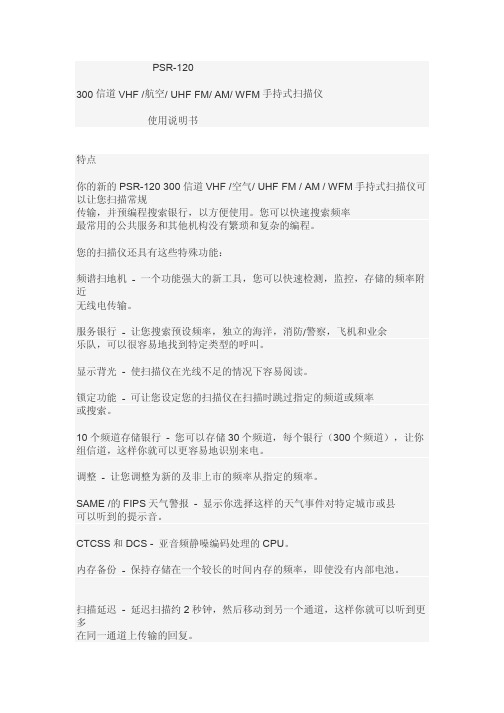
一旦你理解了本手册中使用的一些简单的术语,熟悉扫描仪的功能, 你可以把扫描仪为你工作。您只需确定你想要的类型的通信 接收,然后将扫描仪进行扫描。
的频率是接收信号的位置(kHz 或 MHz)。找到活动的频率,你可以使用 搜索或调整功能。
当你找到一个频率,你可以把它存储到一个可编程存储器单元称为一个通道,这 是 与其他信道进行分组一个通道存储银行中。然后,您可以扫描通道存储银行 存储在那里的频率是否有活动。每次扫描仪找到一个活动的频率,它停留在 该通道,直到发送结束。这种扫描仪具有独立的通道扫描仪模式之间的位置 (共 300 个通道)和 FM 收音机模式(共 20 个通道)。
3。 装入三节 AA 电池,匹配的极性符号(+, - )标记内。
4。 更换的电池仓盖。 设置的 ALK 如果您使用碱性 batteriesSet 如果您使用的镍氢(Ni-MH)充电 镍氢(Ni-MH)电池
警告:切勿安装碱性电池,镍氢(Ni-MH)电池类型选择开关设置。碱性 电池会变热,或爆炸,如果您尝试充电。
交通安全
驾驶机动车或骑自行车时不要戴耳机或耳机与您的扫描仪 或附近的交通。这样做可能会造成交通事故的危险,并在某些领域可能是非法的。
如果您在使用耳机或耳机与您的扫描仪,而骑自行车时,要非常小心。不要听 一个连续的广播。尽管一些耳机和耳机让你听到一些外界的声音, 当你听到他们在正常水平,还可以出现的交通危险。
警告:为避免触电,请勿使用 AC 适配器的极化插头的扩展名 电源线,插座或其它电源插座,除非你能完全插入,以防止刀片的刀片 曝光。
充电电池
本机的充电方法是最简单的充电方法。
,而他们在你的扫描仪可充电镍金属氢化物(镍氢)充电电池(不提供) 扫描仪。确保安装了镍氢(Ni-MH)电池和镍氢(Ni-MH)电池类型选择开关设 置为。对 为充电电池进行充电,则需要使用附带的 AC 适配器。
全国电台频率表
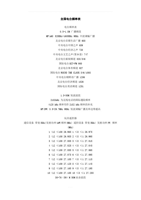
全国电台频率表电台频率表0.5-1.8M 广播频段MF(AM) 525KHz-1605KHz 9KHz 中波调幅广播北京电台首都生活广播 603中央电台中国之声 639中央电台经济之声 720中央电台文艺之声(第9套) 747北京电台新闻频道 828/846国际电台HIT-FM 900北京电台体育频道 927国际电台ROUND THE CLOCK 846/1008中央电台朝鲜语广播 1206北京电台经济频道 1026国际电台英语频道 12511.8-30M 短波波段2182kHz 为无线电话的国际遇险频率4125 kHz频率用作2182 kHz频率的补充HF(SW) 3.5-29.7MHz 9KHz 短波调幅广播及单边带通讯玩具遥控器通信设备带宽(KHz)发射功率(mW)频率(MHz) 遥控设备带宽(KHz) 发射功率(W) 频率(MHz)1 <12 ≤100 26.965 1 ≤8 ≤1 26.9752 <12 ≤100 26.985 2 ≤8 ≤1 26.9953 <12 ≤100 27.005 3 ≤8 ≤1 27.0154 <12 ≤100 27.025 4 ≤8 ≤1 27.0455 <12 ≤100 27.055 5 ≤8 ≤1 27.0656 <12 ≤100 27.075 6 ≤8 ≤1 27.0957 <12 ≤100 27.105 7 ≤8 ≤1 27.1158 <12 ≤100 27.125 8 ≤8 ≤1 27.1459 <12 ≤100 27.165 9 ≤8 ≤1 27.19510 <12 ≤100 27.185 10 ≤8 ≤1 27.25530-76(59)M 50M业余波段无绳电话使用频率划分表一座机频率(MHz) 手机发射频率(MHz)1 48.000 74.0002 48.025 74.0253 48.050 74.0504 48.075 74.0755 48.100 74.1006 48.125 74.1257 48.150 74.1508 48.175 74.1759 48.200 74.20010 48.225 74.22511 48.250 74.25012 48.275 74.27513 48.300 74.30014 48.325 74.32515 48.350 74.35016 1.665 48.37517 1.690 48.40018 1.715 48.42519 1.690 48.45020 1.740 48.475无绳电话使用频率划分表二座机发射(MHz) 手机发射(MHz)1 45.000 48.0002 45.025 48.0253 45.050 48.0504 45.075 48.0755 45.100 48.1006 45.125 48.1257 45.150 48.1508 45.175 48.1759 45.200 48.20010 45.225 48.225VHF 48.5-92MHz 8MHz 电视及数据广播中国电视频道频率划分表 (单位:MHz)频道号/频率范围图像载频伴音载频VHF-L (Ⅰ)DS-1 48.5~56.5 49.75 56.25DS-2 56.5~64.5 57.75 64.25DS-3 64.5~72.5 65.75 72.25DS-4 76.0~84.0 77.25 83.75DS-5 84.0~92.0 85.25 91.7564.5-72.5M (广播为主)76(59)-108M 调频广播VHF(FM) 88-108MHz 150KHz 调频广播及数据广播北京 87.6 北京人民广播电台文艺台北京 88.2 中国国际广播电台EasyFM北京 88.7 中国国际广播电台北京 90.0 中央人民广播电台第三套节目文艺调频北京 91.5 中国国际广播电台EasyFM北京 96.6 中央人民广播电台第二套节目经济频道北京 97.4 北京人民广播电台音乐台北京 99.6 中央人民广播电台第二套节目北京 101.8 中央人民广播电台第四套节目民族广播北京 103.9 北京人民广播电台交通台北京 106.1 中央人民广播电台第一套节目综合频道108-137M 航空波段121.5MHz频率用于遇险和紧急时的无线电话137-174M 144M 业余波段(144-146 发射)船对海岸电台的话通信的频率单在VHF段以0.25MHz为步进,共有88个FM频道!是156.025MHZ,156.050MHz,156.075MHz,156.100MHz 156.125MHz,156.150MHz,156.175MHz,156.200MHz.............156.700MHz,156.725MHz,156.750MHz.遇险,安全和呼叫频率:156.800MHz FM156.850MHz,156.875MHz,156.900MHz........................157.400MHz,156.425MHz遇险频率:500KHz CW; 2182KHz AM; 8364KHz CW中国海事固定频率表中国海事SSB固定频率海事通讯SSB固定频率频率:khz一、广州海岸电台频道号岸台发射频率(KHz) 岸台守听频率(KHz) 工作时间(北京时间)天线方向822 8782 8258 H24 全向837 8716 8170 应邀而开全向1208 13098 12251 应邀而开全向1211 13107 12260 H24 全向1225 13149 12302 H24 全向1236 13182 12335 H24 全向1616 17287 16405 1600-2300L 全向1653 17398 16516 H24 全向1806 19770 18795 H24 全向1809 19779 18804 H24 全向1814 19794 18819 1600-2300L 全向2214 22735 22039 H24 全向2220 22753 22057 H24 全向2.每天0900-1600L每小时正点和1700-2300单小时正点在1616频道(发射频率17287 KHz)、1809频道(发射频率19779KHz)播发通话表、海上区域气象信息、新闻。
weinmann WALLTEQ M-120 多功能桥-使用手册说明书

The multifunction bridge WALLTEQ M-120 allows to process wall elements, roof elements, floor or gable elements at highest precision. The wide range of applications enables to produce a wide variety of wall structures and materials quickly and easily – all this at an excellent price-performance ratio.Ideal entry into CNC-controlled productionEntry-level solution with extremely very low acquisition costs for small and medium sized carpentries Constant high qualityPrecize processing through state-of-the-art CNC technologyEasily integrable in production hallsLess space requirement – production of elements up to 12 m requiring only 90 m² of production area Production in batch size 1Flexible production of various elements without changeover timesYour benefits at a glanceProfitable even for small quantities. Our WALLTEQ M-120./weinmannYOUR SOLUTION“We work to a high level of quality and our production is about 30 percent faster than manual production, even with the same number of employees.“ Christoph Bächle, Abbundzentrum St. Johann·Manufacturing of window, door and socket cut-outs·Tracking of and compensation for thickness variations in the element with scanning routing unit·Fully interpolating routing of free-formed pieces such as circles, curves or straight cutsInterpolating routing processingSwiveling chuck for nailing devicesHorizontal swiveling for example in the case of narrow studs or 2” x 4” construction method.Ideal for use in timber constructionFormatting outer edges·Automatic fastening of sheathings ·Two chucks for different clamping and nailing devices·Fastening units can drive in X- and Y-di-rection. This enables the attachment for example of gable inclinations in varoius angles.·Ensures static equilibrium by guarantee-ing the correct border and attachment clearancesFastening of sheathingUseable for different materials and wall constructionsOptional featuresPiggyback suction deviceMinimizes the amount of dust. A dust extraction supplied by the customer is also possible.Fully automatic fastening of sheathings by two different staple or nailing devicesFully automatic processing of the sheathing with routing unitSPACE REQUIREMENT AND TECHNICAL DATA BASIC EDITION ADVANCED EDITION PROFESSIONAL EDITION width (mm)6,0256,0256,025 (during turning process 9 m)length for 6 m elements (m)121919length for 8 m elements (m)142323length for 10 m elements (m)162727length for 12 m elements (m)183131power requirements (kW) WALL TEQ M-120181818power requirements (kW) BUILDTEQ due to machine typ due to machine typ 16compressed air requirements (Nl/min)150015001500State-of-the-art technology for your productionDepending on the performance and product range required, different versions are available to suit your requirements.BASIC EDITION:WALLTEQ M-120 with a single working table·Can be combined with various working tables, for example self assembly table, carpentry table or already existing working tables·Optimized working process because of ergonomic wokring methods and better logistic processes·Capacity: 20 houses / year (for approx. 650 m² of panel)ADVANCED EDITION:WALLTEQ M-120 with two working tables·Can be combined with various working tables, for example self assembly table, carpentry table or already existing working tables·High productivity due to parallel working on both tables: Production of the frame work on table 1, insertion of installation and closing of the element on table 2·Capacity: 30 houses / year (for approx. 650 m² of panel)PROFESSIONAL EDITION:WALLTEQ M-120 with butterfly turning table·Multifunction bridge combined with butterfly turning table ·Safe and fast turning of the elements within just 90 seconds ·High productivity due to parallel working, automated turning and optimized working processes·Capacity: 35 houses / year (for approx. 650 m² of panel)S t a t u s 04/20 | T e c h n i c a l c h a n g e s , p r i n t e r r o r s a n d m i s t a k e s r e s e r v e d . P i c t u r e s m a y s h o w s p e c i a l e q u i p m e n t ./weinmannYOUR SOLUTION。
AM与FM性能的比较..
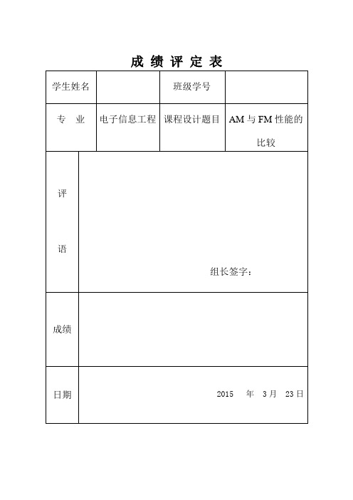
成绩评定表学生姓名班级学号专业电子信息工程课程设计题目AM与FM性能的比较评语组长签字:成绩日期2015 年 3月 23日课程设计任务书学院信息科学与工程专业电子信息工程学生姓名班级学号课程设计题目AM与FM性能的比较实践教学要求与任务:利用MATLAB/Simulink进行编程和仿真,分别设计AM与FM调制解调通信系统,并对AM与FM调制解调系统进行仿真,比较二者的性能优劣及适应环境工作计划与进度安排:2015年 03月19 日选题目查阅资料2015年 03月20 日编写软件源程序或建立仿真模块图2015年 03月21 日调试程序或仿真模型2015年 03月21 日性能分析及验收2015年 03月22 日撰写课程设计报告、答辩指导教师:2015年 3月19日专业负责人:2015年 3月19日学院教学副院长:2015年 3月19日摘要AM是指调幅使高频载波的振幅随信号改变的调制,其中,载波信号的振幅随着调制信号的某种特征的变换而变化。
FM是指其基本特征是载波的振荡幅度保持不变,振荡频率随调制信号而变,就是高频载波的频率不是一个常数,是随调制信号而在一定范围内变化的调制方式,其幅值则是一个常数。
与其对应的,调幅就是载频的频率是不变的,其幅值随调制信号而变。
本设计是通过MATLAB/Simulink对AM和FM进行调制解调,并在不同环境查看AM与FM时域与频域波形,进行比对,并得出仿真结果,分析比较两种种不同的调制方式所存在的不同。
关键词:AM;FM;调制解调;MATLAB;目录1 课程设计目的 (1)2 课程设计要求 (1)3 相关知识 (1)4 课程设计分析 (2)5仿真 (4)6结果分析 (11)7参考文献 (17)(1)分别设计AM,FM,调制与解调通信系统,分别在理信道和非理想信道中运行,并得出仿真结果,分析比较两种种不同的调制方式所存在的不同。
(2)熟悉MATLAB文件中M文件的使用方法,包括函数、原理和方法的应用。
FMM22-05PF;中文规格书,Datasheet资料
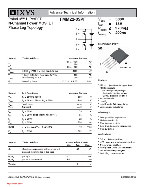
© 2008 IXYS CORPORATION, All rights reservedN-Channel Power MOSFET Phase Leg TopologyDS100039(09/08)SymbolTest Conditions Characteristic Values Min. Typ. Max.C P Coupling capacitance between shorted 40 pFpins and mounting tab in the case d S ,d A pin - pin 1.7 mm d S ,d A pin - backside metal 5.5mmWeight9gFeatureszSilicon chip on Direct-Copper Bond (DCB) substrate- UL recognized package - Isolated mounting surface - 2500V electrical isolation z Avalanche rated z Low Q Gz Low Drain-to-Tab capacitance zLow package inductanceAdvantagesz Low gate drive requirement z High power density z Fast intrinsic rectifierz Low drain to ground capacitance zFast switchingApplicationszDC and AC motor drivesz UPS, solar and wind power inverters z Synchronous rectifiersz Multi-phase DC to DC converters z Industrial battery chargers zSwitching power suppliesSymbol Test Conditions Maximum Ratings V DSS T J = 25°C to 150°C500 V V DGR T J = 25°C to 150°C, R GS = 1M Ω 500VV GSS Continuous ± 30 V V GSM Transient ± 40 V I D25T C = 25°C13A I DM T C = 25°C, pulse width limited by T JM 55AI A T C = 25°C 22 AE AS T C = 25°C750 mJ dV/dt IS ≤ I DM , V DD ≤ V DSS ,T J ≤ 150°C 10 V/ns PDT C = 25°C132WSymbol Test Conditions Maximum Ratings T J -55 ... +150°C T JM 150°C T stg -55 ... +150°C V ISOLD 50/60H Z , RMS, t = 1min, leads-to-tab 2500~V T L1.6mm (0.062 in.) from case for 10s 300°C T SOLD Plastic body for 10s260°C F CMounting force 20..120 / 4.5..27N/lb.DSSI D25= 13A R DS(on)≤ 270m Ωt rr(max)≤ 200nsISOPLUS i4-Pak TM15Source-Drain Diode Characteristic ValuesT = 25°C unless otherwise specified)Note 1: Pulse test, t≤ 300μs, duty cycle, d ≤ 2 %.ADVANCE TECHNICAL INFORMATIONThe product presented herein is under development. The Technical Specifications offered arederived from a subjective evaluation of the design, based upon prior knowledge and experience,and constitute a "considered reflection" of the anticipated objective result. IXYS reserves the rightto change limits, test conditions, and dimensions without notice.IXYS reserves the right to change limits, test conditions, and dimensions.IXYS MOSFETs and IGBTs are covered4,835,5924,931,8445,049,9615,237,4816,162,6656,404,065 B16,683,3446,727,5857,005,734 B2 7,157,338B2 by one or more of the following U.S. patents:4,850,0725,017,5085,063,3075,381,0256,259,123 B16,534,3436,710,405 B26,759,6927,063,975 B24,881,1065,034,7965,187,1175,486,7156,306,728 B16,583,5056,710,4636,771,478 B27,071,537分销商库存信息: IXYSFMM22-05PF。
FM120中文资料
RECTRON
SEMICONDUCTOR
TECHNICAL SPECIFICATION
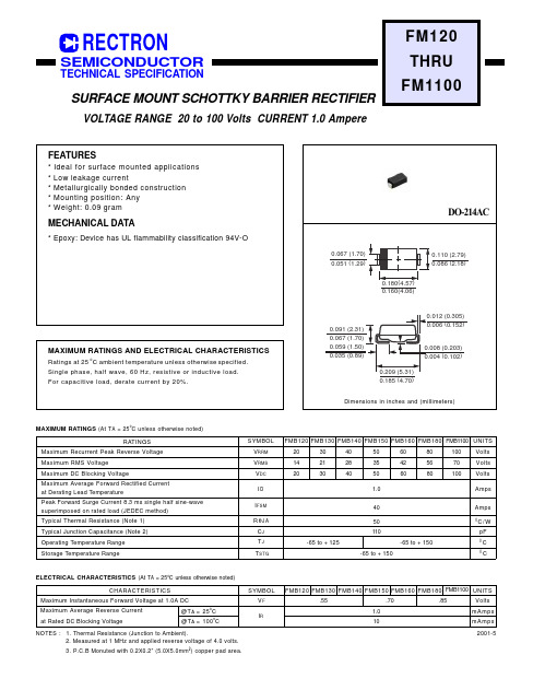
SURFACE MOUNT SCHOTTKY BARRIER RECTIFIER
VOLTAGE RANGE 20 to 100 Volts CURRENT 1.0 Ampere
RθJA CJ TJ TSTG
-65 to + 125
40
50 110
-65 to + 150 -65 to + 150
Amps
0C/ W pF 0C 0C
ELECTRICAL CHARACTERISTICS (At TA = 25oC unless otherwise noted)
CHARACTERISTICS
MAXIMUM RATINGS (At TA = 25oC unless otherwise noted)
RATINGS Maximum Recurrent Peak Reverse Voltage Maximum RMS Voltage Maximum DC Blocking Voltage Maximum Average Forward Rectified Current at Derating Lead Temperature Peak Forward Surge Current 8.3 ms single half sine-wave superimposed on rated load (JEDEC method) Typical Thermal Resistance (Note 1) Typical Junction Capacitance (Note 2) Operating Temperature Range Storage Temperature Range
FM中文资料
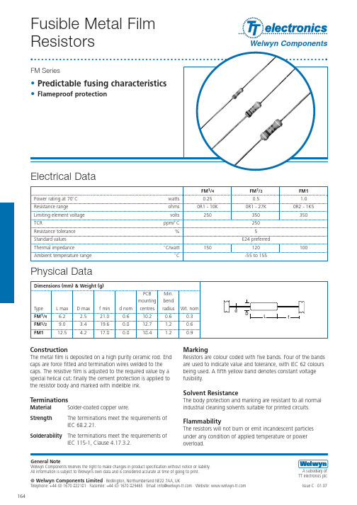
General Note
Welwyn Components reserves the right to make changes in product specification without notice or liability. All information is subject to Welwyn’s own data and is considered accurate at time of going to print. A subsidiary of TT electronics plc Issue C · 03.02 B 01.07
f2 6 1.4 mm
Standard Quantities Per Package
Type Large ammo pack FM1/4 5000 FM1/2 2500 FM1 1500
© Welwyn Components Limited Bedlington, Northumberland NE22 7AA, UK Telephone: +44 (0) 1670 822181 · Facsimile: +44 (0) 1670 829465 · Email: info@ · Website:
Marking
Resistors are colour coded with five bands. Four of the bands are used to indicate value and tolerance, with IEC 62 colours being used. A fifth yellow band denotes constant voltage fusibility.
Solvent Resistance Terminations
千寻魔方 MC120M 北斗高精度定位模组数据手册说明书
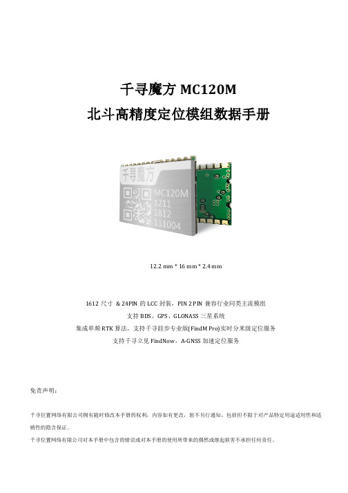
3.1 管脚定义 ..............................................................................................................................................................9 3.2 管脚定义表 ..........................................................................................................................................................9 3.3 参考设计 ........................................................................................................................................................... 10 3.4 机械尺寸 ........................................................................................................................................................... 11
2 模组接口说明 .........................................................................................................................................................7
FMM120资料

VOLTAGE RANGE 20 to 40 Volts CURRENT 1.0 AmpereMAXIMUM RATINGS (@ T A =25 O C unless otherwise noted)ELECTRICAL CHARACTERISTICS (@T A =25 O C unless otherwise noted)RATINGSMaximum Recurrent Peak Reverse Voltage Maximum RMS Voltage Maximum DC Blocking VoltageMaximum Average Forward Rectified Current at T A =75O CPeak Forward Surge Current 8.3 ms single half sine-wave superimposed on rated load (JEDEC method)Typical Thermal Resistance (Note 1)Typical Junction Capacitance (Note 2)SYMBOL V RRM V DC I FSM C J T STGV RMS UNITS Volts Volts Volts Amps 1.04085110Amps0C/W 0C/W 0C Storage Temperature RangeR q J A Typical Thermal Resistance (Note 1)25R q J L I O pFOperating Temperature Range T J FMM12020150-55 to + 150CFMM130FMM1403040142128203040FMM120FMM130FMM1402006-11CHARACTERISTICSMaximum Average Reverse Current at Rated DC Blocking VoltageV F SYMBOL I RmA Maximum Instantaneous Forward Voltage at 1.0A DC Volts 1.010@T A = 25o C @T A = 100oCmA UNITS .44NOTES : 1. Thermal Resistance : Mounted on PCB.2. Measured at 1 MHz and applied reverse voltage of 4.0 volts.3. Also available in DO-214AA (SMB).4. “Fully ROHS compliant”, “100% Sn plating (Pb-free)”.PERCENT OF RATED PEAK REVERSE VOLTAGE, (%)INSTANTANEOUS FORWARD VOLTAGE, (V)I N S T A N T A N E O U S F O R W A R D C U R R E N T , (m A )AMBIENT TEMPERATURE, (OC)A V E R A G E F O R WA R D C U R RE N T , (A )C J , J U N C T I O N C A P A C I T A N C E , (p F )0.11.01020RATING AND CHARACTERISTICS CURVES ( FMM120 THRU FMM140 )FIG.3 TYPICAL INSTANTANEOUS FORWARD CHARACTERISTICSFIG.1 TYPICAL FORWARD CURRENT DERATING CURVEFIG.2 TYPICAL REVERSE CHARACTERISTICSREVERSE VOLTAGE, (V)I N S T A N T A N E O U S R E V E R S E C U R R E N T , (A )FIG.4 TYPICAL JUNCTION CAPACITANCENUMBER OF CYCLES AT 60HzP E A K F O R W A R D S U R G E C U R R E N T , (A )FIG.5 MAXIMUM NON-REPETITIVE FORWARD SURGE CURRENTMounting Pad LayoutDimensions in inches and (millimeters)Rectron Inc reserves the right to make changes without notice to any productspecification herein, to make corrections, modifications, enhancements or other changes. Rectron Inc or anyone on its behalf assumes no responsibility or liabi- lity for any errors or inaccuracies. Data sheet specifications and its information contained are intended to provide a product description only. "Typical" paramet- ers which may be included on RECTRON data sheets and/ or specifications ca- n and do vary in different applications and actual performance may vary over ti- me. Rectron Inc does not assume any liability arising out of the application or use of any product or circuit.Rectron products are not designed, intended or authorized for use in medical, life-saving implant or other applications intended for life-sustaining or other rela- ted applications where a failure or malfunction of component or circuitry may di- rectly or indirectly cause injury or threaten a life without expressed written appr- oval of Rectron Inc. Customers using or selling Rectron components for use in such applications do so at their own risk and shall agree to fully indemnify Rect- ron Inc and its subsidiaries harmless against all claims, damages and expendit- ures.DISCLAIMER NOTICE。
FM中文数据手册

产品资料
最终数据表,包括保证最小和最大限度的电气规格。产品数据表取代所有以 前的文件版本。
注意
每个案例已经确保这个数据表内容的准确性,富迪不能接受任何错误的责 任。富迪有权对其产品作为其发展计划的一部分,使技术的变化。
5
图解
图 1:LQFP 引脚配置................................................................................................9
图 16:IIS 的上升沿锁存,LRCK 高为右声道,0 个周期的延迟.....................31
图 17:模拟到数字转换器框图...............................................................................32
图 10:IIS 的下降沿锁存,LRCK 高左声道,0 个周期的延迟..........................28
图 11:IIS 的下降沿锁存,LRCK 高为右声道,1 个周期的延迟.....................28
图 12:IIS 的下降沿锁存,LRCK 高为右声道,0 个周期的延迟.....................29
2
目录
1. 简介............................................................. 9 1.1 概述......................................................... 9 1.2 个主要特点................................................... 9 1.3 引脚配置(LQFP)............................................ 10 1.4 设备终端功能................................................ 11 1.5 内部硬件框图................................................ 14 1.6 系统应用程序框图............................................ 15
120N100,100V,120A,低压MOS,广泛应用于BMS,动力保护板,无刷电机控制器,伺服驱动控制器等
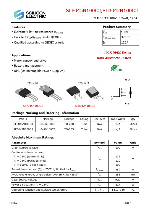
3.0
VGS=10V
2.5
ID=50A
Fig 6: Capacitance Characteristics
10000
Ciss
C - Capacitance (PF)
RDS(on)_Normalized
2.0
1000
Coss
1.5
1.0
100
0.5
0.0 -50 -25 0 25 50 75 100 125 150 175
Tj - Junction Temperature (°C)
10 0
VGS=0V
f=1MHz
Crss
10 20 30 40 50 60 70 80 90 100
VDS (V)
Rev1.0
Page 4
VGS (V)
SFP045N100C3,SFB042N100C3
N-MOSFET 100V, 3.9mΩ, 120A
1.30 1.00
1.25
1.38
0.40
0.65
1.15
1.45
9.85
10.30
0.136
0.100 Typ. 0.276Ref.
Max. 0.192 0.106 0.374 0.059 0.026 0.057 0.406 0.384 0.516
0.204 0.118 0.331 0.012 0.547 0.134
0.150
Rev1.0
Page 8
Package Outline: TO-263
-
3
4
0.05 -
±10
1 10 ±100
3.9
4.5
3.7
4.2
50
upn 120 对应的规格
upn 120 对应的规格摘要:1.概述2.upn 120 的规格参数3.upn 120 的性能特点4.适用范围和场景5.总结正文:1.概述upn 120 是一种工业级无线网络模块,具有高性能、低功耗、稳定性强等特点,广泛应用于物联网、工业自动化、智能家居等领域。
本文将详细介绍upn 120 的规格、性能特点以及适用范围和场景。
2.upn 120 的规格参数upn 120 具有以下规格参数:- 传输速率:10/100Mbps- 频率范围:2.4GHz- 工作电压:3.3V- 工作电流:120mA- 接收灵敏度:-85dBm- 发射功率:18dBm- 传输距离:100 米(视环境而定)- 接口:通过SMA 接口与外部天线连接3.upn 120 的性能特点upn 120 具有以下性能特点:- 高性能:支持高速数据传输,满足各种应用场景的需求。
- 低功耗:工作电流仅为120mA,适合长时间运行的设备。
- 稳定性强:采用2.4GHz 频段,抗干扰能力强,传输稳定。
- 支持多种网络协议:包括TCP/IP、UDP、HTTP 等,方便用户进行网络配置。
4.适用范围和场景upn 120 适用于以下范围和场景:- 工业自动化:如生产线监控、设备数据采集等。
- 智能家居:如智能插座、智能灯泡、智能摄像头等。
- 物联网:如智能交通、智能农业、智能医疗等。
- 无线传感器网络:如环境监测、温湿度监控等。
5.总结upn 120 凭借其高性能、低功耗、稳定性强等特点,在工业自动化、智能家居、物联网等领域具有广泛的应用前景。
萨基姆FMX120培训手册.

1 概述
目标: 认识 FMX设备的不同组成部分 • 1.1 概述 • 1.2 机架 • 1.3 插座 • 1.4 功能
1.1 概述
数字交叉设备
• • • 数字交叉复用设备 64kbit/s Nx64kbit/s 容量 26x2M 数据流(内部交叉连接) 功能
典型应用
LCT 操作
告警Leabharlann 7 V24/V28 接口卡
前面板
特点
• V24/V28有四个点对点连接的接口 • 4个独立、标准DCE类型的接口: • 同步: 速率 1200bit/s to 64kbit/s • 异步: 速率 600bit/s to 38400bit/s • V.110 速率适配
• 接口通道的安排
远端LCT
• 通过EOW网络的帧中继连接 • 通过COB卡运行 • HDLC协议 • 速率: 8kbit/s ( 奇数帧TS0的2bit) 64kbit/s (占用一个时隙传送)
远端LCT(帧中继)
RMS连接
• Remote Management System • RMS 可以管理所有网络设备 • 通过网关设备的TMN接口
1.4 功能描述
• FMX有两种类型的模块: • 公共单元 • 接口卡
FMX接口卡(1)
• • • • • • • 1-4X2MBIT/S (A2S CARD) 3X64KBIT/S (3 64 I CARD) 3XV.24/V.11 4XV.24/V.28 6通道四线E&M (6PAFC CARD) 6通道用户接口卡 (SUBSCR) 12通道交换侧接口卡(EXCH12)
各种数据类型
例如:
• • • • 电话和音频通道 低/中/高速数据通道 2.048M PMC 通道 ISDN接入 (PRI 或BRI)
FM系列硬件系统手册

1993-2004 Copyright Hollysys
和利时、HollySys、HOLLiAS 及
的商标或注册商标。
的字样和徽标均为和利时系统工程股份有限公司
Microsoft、Windows 和 WindowsNT 是微软公司在美国和/或其他国家分支机构的商标或注册商 标。
手册中涉及到的其他商标或注册商标属于他们各自的拥有者。
供电系统及接地要求.......................................................................................................................... 20
供电系统说明........................................................................................................................................................... 20 接地要求................................................................................................................................................................... 21
系统电源模块...................................................................................................................................... 26
AM FM 收音机功能手册说明书
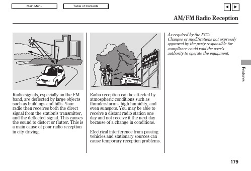
Radio signals,especially on the FM band,are deflected by large objects such as buildings and hills.Your radio then receives both the direct signal from the station’s transmitter,and the deflected signal.This causes the sound to distort or flutter.This is a main cause of poor radio reception in city driving.As required by the FCC:Changes or modifications not expressly approved by the party responsible for compliance could void the user’s authority to operate the equipment.AM/FM Radio ReceptionFeatures179The auxiliary input jack isunderneath the accessory power socket in the console compartment.The system will accept auxiliary input from standard audioaccessories using a 1/8inch stereo miniplug.When a compatible audio unit isconnected to the jack,press the AUX button to select it.Auxiliary Input Jack180The VOL button adjusts the volume up ()or down ().Press the top or bottom of the button,hold it until the desired volume is reached,then release it.If you are listening to the radio,use the CH button to change stations.Each time you press the top ()of the button,the system goes to the next preset station on the band you are listening to.Press the bottom ()to go back to the previous station.Three controls for the audio system are mounted in the steering wheel hub.These let you control basic functions without removing your hand from the wheel.The MODE button changes the mode.Pressing the buttonrepeatedly selects FM1,FM2,AM,XM Radio (U.S.models),a disc (if a disc is loaded),or a tape (if a tape is loaded).To activate the seek function,press and hold the top ()or bottom ()of the CH button until you hear a beep.The system searches up or down from the current frequency to find a station with a strong signal.If you are playing a disc,the system skips to the beginning of the next track (file in MP3or WMA format)each time you press the top ()of the CH button.Press the bottom ()to return to the beginning of the current track or file.Press it twice to return to the previous track or file.You will see the track/file number and the elapsed time.If the disc has text data or is compressed in MP3or WMA,you can also see any other information (track title,file name,folder name,etc.).CONTINUEDRemote Audio ControlsFeatures181If you make a mistake entering the code,do not start over;complete the five-digit sequence,then enter the correct code.You have 10tries to enter the correct code.If you are unsuccessful in 10attempts,you must then leave the system on for 1hour before trying again.Your vehicle’s audio system will disable itself if it is disconnected from electrical power for any reason.To make it work again,you must enter a specific five-digit code in the preset buttons.Because there are hundreds of number combinations possible from five digits,making the system work without knowing the exact code is nearly impossible.You should have received a card that lists your audio system code number and serial number.It is best to store this card in a safe place at home.In addition,you should write the audio system’s serial number in this owner’s manual.If you should happen to lose the card,you must obtain the code number from your dealer.To do this,you will need the system’s serial number.If your vehicle’s battery is discon-nected or goes dead,the audio system will disable itself.If thishappens,you will see ‘‘CODE’’in the frequency display the next time you turn on the e the preset buttons to enter the five-digit code.The code is on the radio code card included in your owner’s manual kit.When it is entered correctly,the radio will start playing.If the code card is lost,your dealer can access your code with yourradio’s serial number.To access the serial number,turn the radio on.It must display ‘‘CODE’’,then turn theradio off.Push the preset 1,preset 6,and power buttons at the same time,then quickly release.The serial number will appear.Radio Theft Protection182The security system automatically sets 15 seconds after you lock the doors, hood, and trunk. For the system to activate, you must lock the doors from the outside with the key, lock tab, door lock switch, or remote transmitter. The security system indicator next to the driver’s door lock starts blinking immediately to show you the system is setting itself.With the system set, you can still open the trunk with the remote transmitter without triggering the alarm. The alarm will sound if the trunk is opened with the trunk release button on the driver’s door, the trunk release handle behind the trunk pass-through cover, or the emergency trunk opener.Do not attempt to alter this system or add other devices to it.The security system helps to protect your vehicle and valuables from theft. The horn sounds and a combination of headlights, parking lights, side marker lights and taillights flash if someone attempts to break into your vehicle or remove the radio.This alarm continues for 2 minutes, then the system resets. To reset analarming system before the 2 minutes have elapsed, unlock the driver’s door with the key or use the remote transmitter.The security system will not set ifthe hood,trunk,or any door is notfully closed.If the system will not set, check the door and trunk openmonitor on the multi-information display(see page)to see if thedoors and trunk are fully closed.Since it is not part of the monitor display,manually check the hood.68Security SystemFeatures183Cruise control allows you to maintain a set speed above 25mph (40km/h)without keeping your foot on the accelerator pedal.It should be used for cruising on straight,openhighways.It is not recommended for city driving,winding roads,slippery roads,heavy rain,or bad weather.When climbing a steep hill,the automatic transmission may downshift to hold the set speed.Press and release the SET/DECEL button on the steering wheel.The CRUISE CONTROL indicator on the instrument panel comes on to show the system is now activated.Cruise control may not hold the set speed when you are going up and down hills.If your vehicle speed increases going down a hill,use the brakes to slow down.This will cancel the cruise control.To resume the set speed,press the RES/ACCEL button.The CRUISE CONTROL indicator on the instrument panel will come back on.3.Cruise Control184You can increase the set cruising speed in any of these ways:Press and hold the RES/ACCEL button.When you reach thedesired cruising speed,release the button.To increase the speed in very small amounts,tap the RES/ACCEL button.Each time you do this,your vehicle speeds up about 1mph (1.6km/h).Resting your foot on the brake or clutch pedal causes cruise control to cancel.Push on the accelerator pedal.Accelerate to the desired cruising speed,then press the SET/DECEL button.Even with cruise control on,you can still use the accelerator pedal to speed up for passing.Aftercompleting the pass,take your foot off the accelerator pedal.The vehicle will return to the set cruising speed.Changing the Set SpeedCruise ControlFeatures185Tap the brake or clutch pedal.Push the CANCEL button on the steering wheel.You can cancel cruise control in any of these ways:Push the CRUISE button on the steering wheel.Pressing the CRUISE button turns the system completely off and erases the previous cruising speed.When you push the CANCEL button,or tap the brake or clutch pedal,the system remembers the previously set cruising speed.To return to that speed,accelerate to above 25mph (40km/h)and then press andrelease the RES/ACCEL button.The CRUISE CONTROL indicator comes on,and the vehicle accelerates to the same cruising speed as before.Resuming the Set SpeedCancelling Cruise ControlCruise Control186If you are training HomeLink to operate a garage door or gate,you should unplug the motor for that device during training.Repeatedly pressing the remote control button could burn out the motor.HomeLink stores the code in a permanent memory.There should be no need to retrain HomeLink if your vehicle’s battery goes dead or is disconnected.If your garage door opener wasmanufactured before April 1982,you may not be able to programHomeLink to operate it.They do not have the safety feature that causesthe motor to stop and reverse if an obstacle is detected during closing,increasing the risk of injury.The HomeLink UniversalTransceiver built into your vehicle can be programmed to operate up to three remote controlled devices around your home,such as garage doors,lighting,or home security systems.Always refer to the openinginstructions and safety information that came with your garage door opener or other equipment youintend to operate with HomeLink.If you do not have this information,contact the manufacturer of the equipment.If you justreceived your vehicle and have not trained any of the buttons inHomeLink before,you should erase any previously learned codes before training the first button.If you are training the second or third buttons,go directly to step 1.For quick and accurate training,make sure the remote transmitter for the device (garage door,automatic gate,security system,etc.)has a fresh battery.To do this,press and hold the two outside buttons on the HomeLink transceiver for about 10seconds,until the red indicator flashes.Release the buttons,then proceed to step 1in the chart on the next page.Before you begin CONTINUEDGeneral InformationImportant Safety Precautions Training HomeLinkHomeLink Universal TransceiverFeatures187。
FM1201

I/O模块
1 FM1201 模块的基本说明
1.1 简介
FM1201 模块是 DP 总线重复器模块, FM1201 模块和配套的端子底座 FM1303 连接,能实现 DP 重复器功能。此外,FM1201 作为 ProfiBus-DP 的从站,通过 ProfiBus-DP 总线可以把模块的状 态信息上传到 ProfiBus-DP 的主站。
收发器
V+
11
V-
12
通讯
工作
接口 A2 B2 V- V+ 电源
DP2
FM1303
+5VA +5VB
单
片
机
调压
FM1201
图 2-1 FM1303 模块的原理框图
HollySys
3
DP总线重复器模块
3 使用说明
FM1201
3.1 状态指示灯说明
FM1201 模块面板上有 4 个状态指示灯:RDY、COM、DP1 及 DP2。 RDY 和 COM 为模块状态指示灯,显示当前模块的工作和模块与主控单元间的通讯状态。DP1、 DP2 为 DP 总线状态指示灯,分别表示与该 DP 重复器单元相连的两段总线的工作状态。其中灯 DP1 的状态是表示:与 DP 重复器单元四针连接器连接的一段总线上是否有数据传输及数据量大小的情 况;灯 DP2 的状态是表示:与 DP 重复器单元四孔连接器连接的一段总线上是否有数据传输及通讯 数据量大小。具体组合状态及含义如表 3-1 所示。
FM1303四针、孔连接器的定义如下
四针连接器定义:
序号 1 2 3 4
端口
V+ VB1 A1
四孔连接器定义:
序号 1 2 3 4
猫(Cat)120M 120M AWD 摩托吹车说明书

Cat® 120M/120M AWDMotor GradersThe Cat® 120M/120M AWD Motor Grader is designed to help you get more work done in less time. Unprecedented operator comfort and ease of service help to maximize your return on investment.Performance• Programmable Autoshif t option simplifies operation by allowingtransmission to be programmed to shif t at optimal points to matchapplication.• Power Shif t Countershaf t Transmission matches to engine,maximizing power to the ground.• Electronic Throt t le Control helps improve productivit y by providingbest match of horsepower and torque for application demands.Effi ciency• Aggressive blade angle, optimized moldboard cur v ature and largethroat clearance allow material to roll more freely along blade,increasing ef fi ciency.• Hydraulic demand fan automatically adjusts speed according tocooling requirements resulting in more power to the ground andimproved fuel ef fi ciency.• Engine idle shutdown is available to shut down engine af t er a setperiod of time saving fuel and helping reduce emissions.Ease of Operation• Selectable blade lif t modes – Fine, Normal, or Coarse – allow you tochoose the blade lif t modulation mode that best fits your applicationor operating st y le.• Joystick controls with electronically adjustable control pods reducehand and arm movement by 78%, helping reduce operator fatigue.• Lef t joystick controls steering, ar t iculation, return-to-center, wheellean, gear selection, lef t moldboard lif t cylinder and float .• Right joystick controls drawbar, circle and moldboard functions aswell as electronic throt t le control and manual dif f erential lock /unlock .• Ar t iculation Return-to-Center automatically returns machine to astraight frame position from any angle with the touch of a but t on.Safety• Angled cab doors, tapered engine enclosure and sloped rear windowincrease visibility.• Optional rear vision camera enhances sight to rear of machine.Serviceability• Convenient access from the top of the circle to the patented top-adjust wear s t rips and inser t s make them easy to add or replace.• Shimless Moldboard Retention Sys t em uses ver t ical and horizontaladjusting screws to keep moldboard wear strips aligned forreduced blade chat t er and precise blade control.Comfort• Control pods can be adjusted electronically, making it easy toset to ideal operating position.• S t andard Cat Comfor t Series suspension seat is fully adjustable.• High capacit y Heating, Ventilation, and Air Conditioning (H V AC)system dehumidifies and pressurizes cab, sealing out dust, andhelps keep windows clear.Technology• Shut t le Shif t allows smooth, fast direction shif t s without requiringyou to manipulate the throt t le or inching pedal.• Cat Product L i nk™ aids your equipment management with remotemonitoring capabilities.• Optional Stable Blade improves grading precision by decreasingengine speed at 15 percent inter v als when machine bounceis detected then increases engine rpm systematically whengrader stabilizes.• Optional Auto Ar t iculation allows you to ar t iculate automaticallywhile steering in tight spaces or around cur v es, obstacles, andturnarounds.• Optional Cat GR A D E with Cross Slope helps maintain desired crossslope by automatically controlling one side of the blade.• Optional Cat AccuGrade™ uses positioning and guidancetechnologies, machine sensors, and automatic blade control to helpget to grade faster, easier and more ef fi ciently.• Optional Cat Advanced Control Joysticks allow you to controlautomated grading solutions ef fi ciently and safely withoutremoving your hands from the joysticks.Cat® 120M/120M AWD Motor GradersEngine Model Cat C6.6 ACER T™Emissions Brazil MA R-1Base Power (1st gear) – Net 10 3 kW 13 8 hp Base Power (1st gear) – Net (Metric) 14 0 hpV H P Plus Range – Net 10 3-13 6 kW 13 8-18 2 hp V H P Plus Range – Net (Metric) 14 0-185 hp Displacement 6.6 L 4 03 in3 Bore 105 mm 4.13 inS t roke 12 7 mm 5.0 in Torque Rise (VHP Plus) 4 0%Maximum Torque ( V HP Plus-Net) 9 06 N·m 6 68 lbf-f t Maximum Torque (AW D On) 9 63 N·m 710 lbf-f t Speed @ Rated Power 2 ,0 00 rpm Number of Cylinders 6Derating Al t itude 3 505 m 11, 500 f tS t andard Fan Speed – Maximum 1,15 0 rpmS t andard Fan Speed – Minimum 6 00 rpmHigh A m bient Fan Speed – Maximum 1, 650 rpmHigh A m bient Fan Speed – Minimum 6 00 rpmHigh A m bient Capabilit y 5 0° C 12 2° F • Maximum torque ( V HP Plus) measured at 1, 400 rpm.• Net power is tested per ISO 9 24 9, SAE J13 49, and EEC 8 0/12 69 Standards in ef f ect at the time of manufacture.• Net power adver t ised is the power available at rated speed of 2 ,0 00 rpm, measured at the fly w heel when engine is equipped with fan running at minimum speed, air cleaner, muf fl er and alternator.• Power as declared per ISO 14 396Rated Speed = 2 ,0 00 rpmVHP Plus = 175 kW (2 34 hp)• No engine derating required up to 3 048 m (10, 000 f t).Circle – Diameter 15 30 mm 6 0.2 in Drawbar – Height 15 2 mm 6.0 in Drawbar – Width 76.2 mm 3.0 in Front Frame Structure – Height 2 80 mm 11.0 in Front Frame Structure – W i dth 2 55 mm 10.0 in Front A x le – W h eel Lean, Lef t/R ight 18°Front A x le – Total Oscillation per Side 3 2°Gross Vehicle Weight – BaseTotal 16 2 31 kg 3 5,78 3 lb Front A x le 42 20 kg 9, 303 lb Rear A x le 12 011 kg 2 6, 479 lb Gross Vehicle Weight – MaximumTotal 2 2 0 45 kg 4 8,6 01 lb Front A x le 6 839 kg 15,077 lb Rear A x le 15 20 6 kg 3 3, 523 lb Gross Vehicle Weight – Typically EquippedTotal 18 4 00 kg 4 0, 565 lb Front A x le 5090 kg 11,221 lb Rear A x le 13 310 kg 2 9, 343 lbMoldboard – Height 610 mm 24.0 in Arc Radius 413 mm 16.3 in Throat Clearance 13 4 mm 5.2 in Moldboard – Width 3.7 m 12 f t Circle Centershif t – RightCircle Centershif t – Lef t65 6 mm65 6 mm2 5.8 in2 5.8 in Moldboard Sideshif t – RightMoldboard Sideshif t – Lef t6 60 mm510 mm26.0 in20.1 in Blade Tip Range – For w ardBlade Tip Range – Back w ardMaximum Shoulder Reach Outsideof Tires – RightMaximum Shoulder Reach Outsideof Tires – Lef t19 05 mm1742 mm4 0°5°75.0 in6 8.6 in Maximum L i f t Above Ground 427 mm 16.8 in Maximum Depth of Cut 720 mm 2 8. 3 inF o r more complete infor m ation on Cat product s, dealer ser v ices, and indus t r y solutions, v i sit us on the web at © 2 017 CaterpillarAll rights reser v edMaterials and speci fi cations are subject to change wi t hou t not i ce. Feat u red machines in photos may include addi t ional equipment .See your Cat dealer for available opt i ons .C A T, C A T E R PIL L A R, S A F E T , their respective logos, “Caterpillar Yellow ” and t h e “Power Edge” trade dress, as well ascorporate and product iden t i t y used herein, are trademarks of Caterpillar and may not be used wi t hout permission.AE X Q 218 7 (0 7-2017)。
2SC4672中文资料(WILLAS ELECTRONIC)中文数据手册「EasyDatasheet - 矽搜」

SOT-89塑封
1.0A表面装载肖特基整流器-20V- 200V
SOD-123 包
2SC4672 THRU
特征 晶体管(• N批P量N处)理设计,出色功耗报价
特征
更好反向漏电流和耐热性.
• 低 型材表面安装,以便应用程序
低 优饱化和电路电板压空间. • 低功耗,高效率.
2- Thermal Resistance From Junction to Ambient
SYMBOL FM120-MH FM130-MH FM140-MH FM150-MH FM160-MH FM180-MH FM1100-MH
VF
IR
Q
120–270
0.50
0180–390
SYMBOL FM120-M H FM130-MH FM140-MH FM150-MH FM160-MH FM180-MH FM1100-MH FM1150-MH FM1200-MH
V(BR)CBO
V(BVR)RCREMO VRMS
V(BR)EBO VDC I CBIOO IEBO
hIFFESM
IC1=250µA,I 1E3=0 14
(1.55)REF
• 极性:由阴极频带指示
• 任何安装位置:
• 重量:逼近0.011克
FM1200-M
包
包装外形
SOT-89 SOD-123H
.063(1.60)
,
.055(1.40)
Dimensionsin inchesand (millimeters)
最大额定值,电器性能
在25℃环境温度,除非另有规定额定值. 单相半波,60赫兹,感性负载电阻. 对于容性负载,减免电流20%
FM AM 广播频率介绍
FM、AM介绍FM、AM是根据频率对广播的一种分类方式。
一般来说AM频率的电台是相对于远距离传播的节目用的,其福射范围大,是长波,多为一些大电台彩的方式,比如说美车之音啊,中央的一些节目啊,但是其收听效果不好,音质差,我们称为调幅广播。
FM则与之相反,其福射范围小,多在几十公里之内,比如一些城里的,学校里的电台之类,其针对性较强,我们平时听的广播节目多为这类,称为调频广播,音质较好。
【AM/FM介绍】什么是调幅波?什么是调频波?使载波振幅按照调制信号改变的调制方式叫调幅AM。
经过调幅的电波叫调幅波。
它保持着高频载波的频率特性,但包络线的形状则和信号波形相似。
调幅波的振幅大小,由调制信号的强度决定。
调幅波用英文字母AM 表示。
使载波频率按照调制信号改变的调制方式叫调频FM。
已调波频率变化的大小由调制信号的大小决定,变化的周期由调制信号的频率决定。
已调波的振幅保持不变。
调频波的波形,就像是个被压缩得不均匀的弹簧,调频波用英文字母FM表示。
目前,调幅制无线电广播分做长波、中波和短波三个大波段,分别由相应波段的无线电波传送信号。
我国只有中波和短波两个大波段的无线电广播。
中波广播使用的频段大致为550kHz-1600kHz,主要靠地波传播,也伴有部分天波;短波广播使用的频段约为2MHz-24MHz,主要靠天波传播,近距离内伴有地波。
调频制无线电广播多用超短波(甚高频)无线电波传送信号,使用频率约为88MHz-108MHz,主要靠空间波传送信号。
目前,地面的广播电视分做VHF(甚高频或称米波)和UHF(特高频或称分米波)两个频段。
在我国,VHF频段电视使用的频率范围是48.5MHz-3MHz,划分成1-12频道,UHF频段使用的频率范围是470MHz-956MHz,划分成:3-68频道。
它们基本上都是靠空间波传播的。
国际上规定的卫星广播电视有6个频段,主要频段是12kMHz,也是靠空间波传播。
广播节目的发送是在广播电台进行。
- 1、下载文档前请自行甄别文档内容的完整性,平台不提供额外的编辑、内容补充、找答案等附加服务。
- 2、"仅部分预览"的文档,不可在线预览部分如存在完整性等问题,可反馈申请退款(可完整预览的文档不适用该条件!)。
- 3、如文档侵犯您的权益,请联系客服反馈,我们会尽快为您处理(人工客服工作时间:9:00-18:30)。
NOTES : 1. Thermal Resistance (Junction to Ambient). 2. Measured at 1 MHz and applied reverse voltage of 4.0 volts. 3. P.C.B Monuted with 0.2X0.2” (5.0X5.0mm 2) copper pad area.
MAXIMUM RATINGS (At T A = 25 oC unless otherwise noted) RATINGS Maximum Recurrent Peak Reverse Voltage Maximum RMS Voltage Maximum DC Blocking Voltage Maximum Average Forward Rectified Current at Derating Lead Temperature Peak Forward Surge Current 8.3 ms single half sine-wave superimposed on rated load (JEDEC method) Typical Thermal Resistance (Note 1) Typical Junction Capacitance (Note 2) Operating Temperature Range Storage Temperature Range SYMBOL VRRM VRMS VDC IO I FSM RθJA CJ TJ T STG FM120M 20 14 20 1.0 40 50 110 -65 to + 125 -65 to + 150 FM140M 40 28 40 UNITS Volts Volts Volts Amps Amps
元器件交易网
RECTRON
SEMICONDUCTOR
TECHNICAL SPECIFICATION
FM120M THRU FM1Байду номын сангаас0M
SURFACE MOUNT SCHOTTKY BARRIER RECTIFIER
VOLTAGE RANGE 20 to 40 Volts CURRENT 1.0 Ampere
0
C/ W pF
0 0
C C
ELECTRICAL CHARACTERISTICS (At TA = 25oC unless otherwise noted) CHARACTERISTICS Maximum Instantaneous Forward Voltage at 1.0A DC Maximum Average Reverse Current at Rated DC Blocking Voltage @T A = 25 o C @T A = 100 o C SYMBOL VF IR FM120M 0.36 1.0 10 FM140M 0.38 UNITS Volts mAmps mAmps 1998-8
DO-214AC
MAXIMUM RATINGS AND ELECTRICAL CHARACTERISTICS
Ratings at 25 o C ambient temperature unless otherwise specified. Single phase, half wave, 60 Hz, resistive or inductive load. For capacitive load, derate current by 20%. Dimensions in inches and (millimeters)
FEATURES
* * * * * * Glass passivated device Ideal for surface mounted applications Low leakage current Metallurgically bonded construction Mounting position: Any Weight: 0.057 gram
元器件交易网
RECTRON
