广达电脑Rackgo一体化服务器资料
ATEN Altusen CN9950 1-本地远程共享访问单端口 交换机说明书
1-Local / Remote Share Access Single PortKVM over IP SwitchCN9000 / CN9600 / CN9950User ManualCN9000 / CN9600 / CN9950CN9000 / CN9600 / CN9950 User Manual iiEMC InformationFEDERAL COMMUNICATIONS COMMISSION INTERFERENCE STATEMENTThis equipment has been tested and found to comply with the limits for a ClassA digital device, pursuant to Part 15 of the FCC Rules. These limits aredesigned to provide reasonable protection against harmful interference when the equipment is operated in a commercial environment. This equipmentgenerates, uses, and can radiate radio frequency energy and, if not installed and used in accordance with the instruction manual, may cause harmfulinterference to radio communications. Operation of this equipment in aresidential area is likely to cause harmful interference in which case the user will be required to correct the interference at his own expense.This device complies with Part 15 of the FCC Rules. Operation is subject to the following two conditions: (1) this device may not cause harmful interference, and (2) this device must accept any interference received, includinginterference that may cause undesired operation.FCC CautionAny changes or modifications not expressly approved by the party responsible for compliance could void the user's authority to operate this equipment.WarningOperation of this equipment in a residential environment could cause radio interference.AchtungDer Gebrauch dieses Geräts in Wohnumgebung kann Funkstörungen verursachen.KCC Statement :CN9000 / CN9600 / CN9950 User Manual iiiIndustry Canada StatementThis Class A digital apparatus complies with Canadian ICES-003.RoHS This product is RoHS compliant.About This ManualThis manual is provided to help you get the most out of your CN9000 / CN9600 / CN9950. It covers all aspects of the device, including installation,configuration, and operation.The models covered in this manual include:An overview of the information found in the manual is provided below.Chapter 1, Introduction , introduces you to the CN9000 / CN9600 / CN9950 KVM over IP Switch, its purpose, features and benefits, with its front and back panel components described.Chapter 2, Hardware Setup , provides step-by-step instructions for setting up the device, and explains its basic operation procedures.Chapter 3, Browser Login , describes how to log into the CN9000 / CN9600 / CN9950 with a browser, and the various functions included.Chapter 4, Configuration , explains the CN9000 / CN9600 / CN9950’s system settings that can be configured to suit its working environment.Chapter 5, Accessing Remote Server , describes how to access the CN9000 / CN9600 / CN9950 remotely.Model Product Name CN90001-Local / Remote Share Access Single Port VGA KVM over IP Switch CN96001-Local / Remote Share Access Single Port DVI KVM over IP Switch CN99501-Local / Remote Share Access Single Port 4K DisplayPort KVM over IPSwitchCN9000 / CN9600 / CN9950 User Manual ivChapter 6, The Windows Client Viewer , explains how to remotely access the server connected to the CN9000 / CN9600 / CN9950’s port using a WinClient, Java Client, and Web Client viewerChapter 7, Local Access , describes how to access the CN9000 / CN9600 / CN9950 locally.Chapter 8, The Log File , shows how to use the log file utility to view the events that take place on the CN9000 / CN9600 / CN9950.Chapter 9, The Log Server , explains how to install and configure the Log Server.Appendix , provides specifications and other technical information regarding the CN9000 / CN9600 / CN9950.ConventionsThis manual uses the following conventions:MonospacedIndicates text that you should key in.[ ]Indicates keys you should press. For example, [Enter] means topress the Enter key. If keys need to be chorded, they appeartogether in the same bracket with a plus sign between them:[Ctrl+Alt].1.Numbered lists represent procedures with sequential steps.♦Bullet lists provide information, but do not involve sequential steps.>Indicates consecutive selections, such as options on a menu ordialog box. For example, Start > Run means to open the Startmenu, and then select Run .Indicates critical information.CN9000 / CN9600 / CN9950 User Manual Package ContentsCN9000♦1CN9000 KVM over IP Switch♦1KVM cable (SPHD to VGA, PS/2, USB)♦1USB Type-A to USB Mini-B cable♦1power adapter♦1mounting kit♦1control terminal block♦1foot pad set (4 pcs)♦1user instructions*CN9600♦1CN9600 KVM over IP Switch♦1KVM cable (DVI-D, USB Type-A, audio)♦1USB Type-A to USB Mini-B cable♦1power adapter♦1mounting kit♦1user instructions*CN9950♦1CN9950 KVM over IP Switch♦1DisplayPort cable♦1USB Type-A to USB Type-B cable♦1USB Type-A to USB Mini-B cable♦1power adapter♦1mounting kit♦1control terminal block♦1foot pad set (4 pcs)♦1user instructions*vCN9000 / CN9600 / CN9950 User Manual*Features may have been added to the CN9000 / CN9600 / CN9950 since this manual was released. Please visit our website to download the most up-to-date version.Check to make sure that all components are present and in working condition. If you encounter any problems, please contact your local dealer.Read this manual thoroughly and follow the installation and operation procedures to prevent any damage to the unit and/or any devices connected to it.Product InformationFor information about all ATEN products and how they can help you connect without limits, visit ATEN on the Web or contact an ATEN Authorized Reseller. Visit ATEN on the Web for a list of locations and telephone numbers: International North America viCN9000 / CN9600 / CN9950 User Manual User InformationOnline RegistrationBe sure to register your product at our online support center:International Telephone SupportFor telephone support, call this number:International886-2-8692-6959China86-400-810-0-810Japan81-3-5615-5811Korea82-2-467-6789North America1-888-999-ATEN ext 49881-949-428-1111User NoticeAll information, documentation, and specifications contained in this manual are subject to change without prior notification by the manufacturer. The manufacturer makes no representations or warranties, either expressed or implied, with respect to the contents hereof and specifically disclaims any warranties as to merchantability or fitness for any particular purpose. Any of the manufacturer's software described in this manual is sold or licensed as is. Should the programs prove defective following their purchase, the buyer (and not the manufacturer, its distributor, or its dealer), assumes the entire cost of all necessary servicing, repair and any incidental or consequential damages resulting from any defect in the software.The manufacturer of this system is not responsible for any radio and/or TV interference caused by unauthorized modifications to this device. It is the responsibility of the user to correct such interference.The manufacturer is not responsible for any damage incurred in the operation of this system if the correct operational voltage setting was not selected prior to operation. PLEASE VERIFY THAT THE VOLTAGE SETTING IS CORRECT BEFORE USE.viiCN9000 / CN9600 / CN9950 User ManualContentsEMC Information. . . . . . . . . . . . . . . . . . . . . . . . . . . . . . . . . . . . . . . . . . . . . ii About this Manual. . . . . . . . . . . . . . . . . . . . . . . . . . . . . . . . . . . . . . . . . . . .iii Conventions . . . . . . . . . . . . . . . . . . . . . . . . . . . . . . . . . . . . . . . . . . . . .iv Package Contents . . . . . . . . . . . . . . . . . . . . . . . . . . . . . . . . . . . . . . . . . . . v Product Information . . . . . . . . . . . . . . . . . . . . . . . . . . . . . . . . . . . . . . . . . .vi User Information. . . . . . . . . . . . . . . . . . . . . . . . . . . . . . . . . . . . . . . . . . . . vii Online Registration . . . . . . . . . . . . . . . . . . . . . . . . . . . . . . . . . . . . . . . vii Telephone Support . . . . . . . . . . . . . . . . . . . . . . . . . . . . . . . . . . . . . . . vii User Notice. . . . . . . . . . . . . . . . . . . . . . . . . . . . . . . . . . . . . . . . . . . . . vii 1.IntroductionOverview. . . . . . . . . . . . . . . . . . . . . . . . . . . . . . . . . . . . . . . . . . . . . . . . . . .1 Features and Benefits. . . . . . . . . . . . . . . . . . . . . . . . . . . . . . . . . . . . . . . . .2 Hardware. . . . . . . . . . . . . . . . . . . . . . . . . . . . . . . . . . . . . . . . . . . . . . . .2 Management. . . . . . . . . . . . . . . . . . . . . . . . . . . . . . . . . . . . . . . . . . . . .3 Easy-to-Use Interface. . . . . . . . . . . . . . . . . . . . . . . . . . . . . . . . . . . . . .4 Advanced Security . . . . . . . . . . . . . . . . . . . . . . . . . . . . . . . . . . . . . . . .4 Virtual Media. . . . . . . . . . . . . . . . . . . . . . . . . . . . . . . . . . . . . . . . . . . . .4 Virtual Remote Desktop . . . . . . . . . . . . . . . . . . . . . . . . . . . . . . . . . . . .5 System Requirements . . . . . . . . . . . . . . . . . . . . . . . . . . . . . . . . . . . . . . . .6 Remote User Computers . . . . . . . . . . . . . . . . . . . . . . . . . . . . . . . . . . .6 Servers . . . . . . . . . . . . . . . . . . . . . . . . . . . . . . . . . . . . . . . . . . . . . . . . .6 Cables. . . . . . . . . . . . . . . . . . . . . . . . . . . . . . . . . . . . . . . . . . . . . . . . . .7 Supported Video Resolutions . . . . . . . . . . . . . . . . . . . . . . . . . . . . . . . .8 Operating Systems . . . . . . . . . . . . . . . . . . . . . . . . . . . . . . . . . . . . . . . .8 Browsers. . . . . . . . . . . . . . . . . . . . . . . . . . . . . . . . . . . . . . . . . . . . . . . .9 Components. . . . . . . . . . . . . . . . . . . . . . . . . . . . . . . . . . . . . . . . . . . . . . .10 CN9000 Front View. . . . . . . . . . . . . . . . . . . . . . . . . . . . . . . . . . . . . . .10 CN9000 Rear View. . . . . . . . . . . . . . . . . . . . . . . . . . . . . . . . . . . . . . .11 CN9000/CN9950 Side View . . . . . . . . . . . . . . . . . . . . . . . . . . . . . . . .12 CN9950 Front View. . . . . . . . . . . . . . . . . . . . . . . . . . . . . . . . . . . . . . .13 9950 Rear View. . . . . . . . . . . . . . . . . . . . . . . . . . . . . . . . . . . . . . . . . .14 CN9600 Front View. . . . . . . . . . . . . . . . . . . . . . . . . . . . . . . . . . . . . . .15 CN9600 Rear View. . . . . . . . . . . . . . . . . . . . . . . . . . . . . . . . . . . . . . .16 2.Hardware SetupMounting. . . . . . . . . . . . . . . . . . . . . . . . . . . . . . . . . . . . . . . . . . . . . . . . . .17 Attaching the Bracket . . . . . . . . . . . . . . . . . . . . . . . . . . . . . . . . . .17Rack Mount. . . . . . . . . . . . . . . . . . . . . . . . . . . . . . . . . . . . . . . . . .18Wall Mount . . . . . . . . . . . . . . . . . . . . . . . . . . . . . . . . . . . . . . . . . .19 Hardware Installation . . . . . . . . . . . . . . . . . . . . . . . . . . . . . . . . . . . . . . . .20 CN9000. . . . . . . . . . . . . . . . . . . . . . . . . . . . . . . . . . . . . . . . . . . . . . . .21 CN9600. . . . . . . . . . . . . . . . . . . . . . . . . . . . . . . . . . . . . . . . . . . . . . . .22 viiiCN9000 / CN9600 / CN9950 User Manual CN9950. . . . . . . . . . . . . . . . . . . . . . . . . . . . . . . . . . . . . . . . . . . . . . . . . . .23 DCE and DTE Ports . . . . . . . . . . . . . . . . . . . . . . . . . . . . . . . . . . . . . . . . .24 3.Browser LoginLogging In. . . . . . . . . . . . . . . . . . . . . . . . . . . . . . . . . . . . . . . . . . . . . . . . .25 Main Screen . . . . . . . . . . . . . . . . . . . . . . . . . . . . . . . . . . . . . . . . . . . . . . .27 4.ConfigurationIntroduction. . . . . . . . . . . . . . . . . . . . . . . . . . . . . . . . . . . . . . . . . . . . . . . .29 Basic Setting. . . . . . . . . . . . . . . . . . . . . . . . . . . . . . . . . . . . . . . . . . . . . . .30 User Management. . . . . . . . . . . . . . . . . . . . . . . . . . . . . . . . . . . . . . . .30 User Information . . . . . . . . . . . . . . . . . . . . . . . . . . . . . . . . . . . . . .30Role. . . . . . . . . . . . . . . . . . . . . . . . . . . . . . . . . . . . . . . . . . . . . . . .30Permissions. . . . . . . . . . . . . . . . . . . . . . . . . . . . . . . . . . . . . . . . . .31 Account Policy. . . . . . . . . . . . . . . . . . . . . . . . . . . . . . . . . . . . . . . . . . .32 Sessions . . . . . . . . . . . . . . . . . . . . . . . . . . . . . . . . . . . . . . . . . . . . . . .33 Maintenance . . . . . . . . . . . . . . . . . . . . . . . . . . . . . . . . . . . . . . . . . . . .34 Upgrade Main Firmware . . . . . . . . . . . . . . . . . . . . . . . . . . . . . . . .34Update Display Information. . . . . . . . . . . . . . . . . . . . . . . . . . . . . .35Backup / Restore. . . . . . . . . . . . . . . . . . . . . . . . . . . . . . . . . . . . . .36Terminal. . . . . . . . . . . . . . . . . . . . . . . . . . . . . . . . . . . . . . . . . . . . .38 Advanced Setting . . . . . . . . . . . . . . . . . . . . . . . . . . . . . . . . . . . . . . . . . . .39 Device Information . . . . . . . . . . . . . . . . . . . . . . . . . . . . . . . . . . . . . . .39 General . . . . . . . . . . . . . . . . . . . . . . . . . . . . . . . . . . . . . . . . . . . . .39 Network. . . . . . . . . . . . . . . . . . . . . . . . . . . . . . . . . . . . . . . . . . . . . . . .41 IP Installer . . . . . . . . . . . . . . . . . . . . . . . . . . . . . . . . . . . . . . . . . . .42Service Ports. . . . . . . . . . . . . . . . . . . . . . . . . . . . . . . . . . . . . . . . .42Redundant NIC . . . . . . . . . . . . . . . . . . . . . . . . . . . . . . . . . . . . . . .43IPv4 Settings . . . . . . . . . . . . . . . . . . . . . . . . . . . . . . . . . . . . . . . . .43IPv6 Settings . . . . . . . . . . . . . . . . . . . . . . . . . . . . . . . . . . . . . . . . .44Network Transfer Rate. . . . . . . . . . . . . . . . . . . . . . . . . . . . . . . . . .44DDNS. . . . . . . . . . . . . . . . . . . . . . . . . . . . . . . . . . . . . . . . . . . . . . .44 ANMS . . . . . . . . . . . . . . . . . . . . . . . . . . . . . . . . . . . . . . . . . . . . . . . . .45 Event Destination. . . . . . . . . . . . . . . . . . . . . . . . . . . . . . . . . . . . . .45SMTP Settings. . . . . . . . . . . . . . . . . . . . . . . . . . . . . . . . . . . . . . . .46Authentication . . . . . . . . . . . . . . . . . . . . . . . . . . . . . . . . . . . . . . . .48 Security. . . . . . . . . . . . . . . . . . . . . . . . . . . . . . . . . . . . . . . . . . . . . . . .51 Login Failures . . . . . . . . . . . . . . . . . . . . . . . . . . . . . . . . . . . . . . . .51Filter. . . . . . . . . . . . . . . . . . . . . . . . . . . . . . . . . . . . . . . . . . . . . . . .52Encryption . . . . . . . . . . . . . . . . . . . . . . . . . . . . . . . . . . . . . . . . . . .54Security Level . . . . . . . . . . . . . . . . . . . . . . . . . . . . . . . . . . . . . . . .54Mode . . . . . . . . . . . . . . . . . . . . . . . . . . . . . . . . . . . . . . . . . . . . . . .55Private Certificate . . . . . . . . . . . . . . . . . . . . . . . . . . . . . . . . . . . . .55Certificate Signing Request. . . . . . . . . . . . . . . . . . . . . . . . . . . . . .57 Console Management. . . . . . . . . . . . . . . . . . . . . . . . . . . . . . . . . . . . .59 OOBC . . . . . . . . . . . . . . . . . . . . . . . . . . . . . . . . . . . . . . . . . . . . . .59ixCN9000 / CN9600 / CN9950 User ManualxDial Out. . . . . . . . . . . . . . . . . . . . . . . . . . . . . . . . . . . . . . . . . . . . .61 Serial Console. . . . . . . . . . . . . . . . . . . . . . . . . . . . . . . . . . . . . . . .63 Date/Time . . . . . . . . . . . . . . . . . . . . . . . . . . . . . . . . . . . . . . . . . . . . . .66 Time Zone. . . . . . . . . . . . . . . . . . . . . . . . . . . . . . . . . . . . . . . . . . .66 Date / Time . . . . . . . . . . . . . . . . . . . . . . . . . . . . . . . . . . . . . . . . . .66 Network Time . . . . . . . . . . . . . . . . . . . . . . . . . . . . . . . . . . . . . . . .67 Customization. . . . . . . . . . . . . . . . . . . . . . . . . . . . . . . . . . . . . . . . . . .67 Mode. . . . . . . . . . . . . . . . . . . . . . . . . . . . . . . . . . . . . . . . . . . . . . .68 USB IO Settings . . . . . . . . . . . . . . . . . . . . . . . . . . . . . . . . . . . . . .68 Multiuser Mode . . . . . . . . . . . . . . . . . . . . . . . . . . . . . . . . . . . . . . .68 Exit Macro. . . . . . . . . . . . . . . . . . . . . . . . . . . . . . . . . . . . . . . . . . .69 Reset. . . . . . . . . . . . . . . . . . . . . . . . . . . . . . . . . . . . . . . . . . . . . . .69 Preferences . . . . . . . . . . . . . . . . . . . . . . . . . . . . . . . . . . . . . . . . . . . . . . .70 User Preferences . . . . . . . . . . . . . . . . . . . . . . . . . . . . . . . . . . . . . . . .70 Logs . . . . . . . . . . . . . . . . . . . . . . . . . . . . . . . . . . . . . . . . . . . . . . . . . .71 Remote Console. . . . . . . . . . . . . . . . . . . . . . . . . . . . . . . . . . . . . . . . .72 Remote Console Preview . . . . . . . . . . . . . . . . . . . . . . . . . . . . . . .72 Telnet Viewer . . . . . . . . . . . . . . . . . . . . . . . . . . . . . . . . . . . . . . . .72 Download . . . . . . . . . . . . . . . . . . . . . . . . . . . . . . . . . . . . . . . . . . . . . .73 About . . . . . . . . . . . . . . . . . . . . . . . . . . . . . . . . . . . . . . . . . . . . . . . . . . . .73 Viewer. . . . . . . . . . . . . . . . . . . . . . . . . . . . . . . . . . . . . . . . . . . . . . . . . . . .73 Logout. . . . . . . . . . . . . . . . . . . . . . . . . . . . . . . . . . . . . . . . . . . . . . . . . . . .745.Accessing Remote ServerIntroduction. . . . . . . . . . . . . . . . . . . . . . . . . . . . . . . . . . . . . . . . . . . . . . . .75 Web, Windows and Java Client Viewer . . . . . . . . . . . . . . . . . . . . . . . . . .76 The Windows Client AP . . . . . . . . . . . . . . . . . . . . . . . . . . . . . . . . . . . . . .77 Download . . . . . . . . . . . . . . . . . . . . . . . . . . . . . . . . . . . . . . . . . . . . . .77 Starting Up . . . . . . . . . . . . . . . . . . . . . . . . . . . . . . . . . . . . . . . . . . . . .77 The Java Client AP. . . . . . . . . . . . . . . . . . . . . . . . . . . . . . . . . . . . . . . . . .80 6.The Windows Client ViewerThe Win / Java Client Control Panel. . . . . . . . . . . . . . . . . . . . . . . . . . . . .81 Control Panel Functions . . . . . . . . . . . . . . . . . . . . . . . . . . . . . . . . . . .82 Macros . . . . . . . . . . . . . . . . . . . . . . . . . . . . . . . . . . . . . . . . . . . . . . . .85 Hotkeys. . . . . . . . . . . . . . . . . . . . . . . . . . . . . . . . . . . . . . . . . . . . .85User Macros . . . . . . . . . . . . . . . . . . . . . . . . . . . . . . . . . . . . . . . . .87System Macros . . . . . . . . . . . . . . . . . . . . . . . . . . . . . . . . . . . . . . .91 Video Settings. . . . . . . . . . . . . . . . . . . . . . . . . . . . . . . . . . . . . . . . . . .93 Gamma Adjustment. . . . . . . . . . . . . . . . . . . . . . . . . . . . . . . . . . . .94 The Message Board . . . . . . . . . . . . . . . . . . . . . . . . . . . . . . . . . . . . . .96 The Button Bar . . . . . . . . . . . . . . . . . . . . . . . . . . . . . . . . . . . . . . .96Message Display Panel. . . . . . . . . . . . . . . . . . . . . . . . . . . . . . . . .97Compose Panel. . . . . . . . . . . . . . . . . . . . . . . . . . . . . . . . . . . . . . .97User List Panel . . . . . . . . . . . . . . . . . . . . . . . . . . . . . . . . . . . . . . .97CN9000 / CN9600 / CN9950 User Manual Virtual Media. . . . . . . . . . . . . . . . . . . . . . . . . . . . . . . . . . . . . . . . . . . .98 Virtual Media Icons . . . . . . . . . . . . . . . . . . . . . . . . . . . . . . . . . . . .98Virtual Media Redirection. . . . . . . . . . . . . . . . . . . . . . . . . . . . . . . .98Smart Card Reader . . . . . . . . . . . . . . . . . . . . . . . . . . . . . . . . . . .101 Zoom. . . . . . . . . . . . . . . . . . . . . . . . . . . . . . . . . . . . . . . . . . . . . . . . .101 The On-Screen Keyboard. . . . . . . . . . . . . . . . . . . . . . . . . . . . . . . . .102 Mouse Pointer Type . . . . . . . . . . . . . . . . . . . . . . . . . . . . . . . . . . . . .103 Mouse DynaSync Mode . . . . . . . . . . . . . . . . . . . . . . . . . . . . . . . . . .104 Automatic Mouse Synchronization (DynaSync). . . . . . . . . . . . . .104Manual Mouse Synchronization. . . . . . . . . . . . . . . . . . . . . . . . . .104Mac and Linux Considerations . . . . . . . . . . . . . . . . . . . . . . . . . .105 Open GUI (Configuration). . . . . . . . . . . . . . . . . . . . . . . . . . . . . . . . .106 Control Panel Configuration . . . . . . . . . . . . . . . . . . . . . . . . . . . . . . .107 The Web Client Control Panel. . . . . . . . . . . . . . . . . . . . . . . . . . . . . . . . .109 Web Client Video Settings. . . . . . . . . . . . . . . . . . . . . . . . . . . . . . . . .110 Web Client On-Screen Keyboard . . . . . . . . . . . . . . . . . . . . . . . . . . .111 Web Client Mouse Pointer Type . . . . . . . . . . . . . . . . . . . . . . . . . . . .111 Virtual Media. . . . . . . . . . . . . . . . . . . . . . . . . . . . . . . . . . . . . . . . . . .112 Web Client Mouse Sync Mode . . . . . . . . . . . . . . . . . . . . . . . . . . . . .113 7.Local AccessLocal Console. . . . . . . . . . . . . . . . . . . . . . . . . . . . . . . . . . . . . . . . . . . . .115 Local OSD. . . . . . . . . . . . . . . . . . . . . . . . . . . . . . . . . . . . . . . . . . . . .117 Laptop USB Console (LUC) . . . . . . . . . . . . . . . . . . . . . . . . . . . . . . . . . .118 8.The Log FileThe Log File Screen . . . . . . . . . . . . . . . . . . . . . . . . . . . . . . . . . . . . . . . .121 9.The Log ServerInstallation. . . . . . . . . . . . . . . . . . . . . . . . . . . . . . . . . . . . . . . . . . . . . . . .123 Starting Up . . . . . . . . . . . . . . . . . . . . . . . . . . . . . . . . . . . . . . . . . . . . . . .123 The Menu Bar. . . . . . . . . . . . . . . . . . . . . . . . . . . . . . . . . . . . . . . . . . . . .124 Configure. . . . . . . . . . . . . . . . . . . . . . . . . . . . . . . . . . . . . . . . . . . . . .125 Events. . . . . . . . . . . . . . . . . . . . . . . . . . . . . . . . . . . . . . . . . . . . . . . .126 Search. . . . . . . . . . . . . . . . . . . . . . . . . . . . . . . . . . . . . . . . . . . . .126Maintenance . . . . . . . . . . . . . . . . . . . . . . . . . . . . . . . . . . . . . . . .127 Options . . . . . . . . . . . . . . . . . . . . . . . . . . . . . . . . . . . . . . . . . . . . . . .127 Help. . . . . . . . . . . . . . . . . . . . . . . . . . . . . . . . . . . . . . . . . . . . . . . . . .128 The Log Server Main Screen . . . . . . . . . . . . . . . . . . . . . . . . . . . . . . . . .128 Overview. . . . . . . . . . . . . . . . . . . . . . . . . . . . . . . . . . . . . . . . . . . . . .128 The List Panel. . . . . . . . . . . . . . . . . . . . . . . . . . . . . . . . . . . . . . . . . .129 Panel Showing Logs of the Selected Units. . . . . . . . . . . . . . . . . . . .129 AppendixSafety Instructions. . . . . . . . . . . . . . . . . . . . . . . . . . . . . . . . . . . . . . . . . .131xiCN9000 / CN9600 / CN9950 User ManualxiiGeneral. . . . . . . . . . . . . . . . . . . . . . . . . . . . . . . . . . . . . . . . . . . . . . .131 Rack Mounting . . . . . . . . . . . . . . . . . . . . . . . . . . . . . . . . . . . . . . . . .133 Technical Support. . . . . . . . . . . . . . . . . . . . . . . . . . . . . . . . . . . . . . . . . .134 International . . . . . . . . . . . . . . . . . . . . . . . . . . . . . . . . . . . . . . . . . . .134 North America. . . . . . . . . . . . . . . . . . . . . . . . . . . . . . . . . . . . . . . . . .134 IP Address Determination. . . . . . . . . . . . . . . . . . . . . . . . . . . . . . . . . . . .135 IP Installer. . . . . . . . . . . . . . . . . . . . . . . . . . . . . . . . . . . . . . . . . . . . .135 Browser. . . . . . . . . . . . . . . . . . . . . . . . . . . . . . . . . . . . . . . . . . . . . . .136 AP Windows Client . . . . . . . . . . . . . . . . . . . . . . . . . . . . . . . . . . . . . .136 IPv6. . . . . . . . . . . . . . . . . . . . . . . . . . . . . . . . . . . . . . . . . . . . . . . . . . . . .138 Link Local IPv6 Address . . . . . . . . . . . . . . . . . . . . . . . . . . . . . . . . . .138 IPv6 Stateless Autoconfiguration . . . . . . . . . . . . . . . . . . . . . . . . . . .139 Port Forwarding . . . . . . . . . . . . . . . . . . . . . . . . . . . . . . . . . . . . . . . . . . .140 Keyboard Emulation. . . . . . . . . . . . . . . . . . . . . . . . . . . . . . . . . . . . . . . .141 Serial Port Pin Assignment. . . . . . . . . . . . . . . . . . . . . . . . . . . . . . . . . . .142 Trusted Certificates. . . . . . . . . . . . . . . . . . . . . . . . . . . . . . . . . . . . . . . . .143 Overview. . . . . . . . . . . . . . . . . . . . . . . . . . . . . . . . . . . . . . . . . . . . . .143 Installing the Certificate. . . . . . . . . . . . . . . . . . . . . . . . . . . . . . . . . . .144 Certificate Trusted. . . . . . . . . . . . . . . . . . . . . . . . . . . . . . . . . . . . . . .145 Mismatch Considerations . . . . . . . . . . . . . . . . . . . . . . . . . . . . . . . . .145 Self-Signed Private Certificates . . . . . . . . . . . . . . . . . . . . . . . . . . . . . . .147 Examples . . . . . . . . . . . . . . . . . . . . . . . . . . . . . . . . . . . . . . . . . . . . .147 Importing the Files. . . . . . . . . . . . . . . . . . . . . . . . . . . . . . . . . . . . . . .147 Troubleshooting . . . . . . . . . . . . . . . . . . . . . . . . . . . . . . . . . . . . . . . . . . .148 General Operation. . . . . . . . . . . . . . . . . . . . . . . . . . . . . . . . . . . . . . .148 Windows . . . . . . . . . . . . . . . . . . . . . . . . . . . . . . . . . . . . . . . . . . . . . .150 Java. . . . . . . . . . . . . . . . . . . . . . . . . . . . . . . . . . . . . . . . . . . . . . . . . .151 Sun Systems. . . . . . . . . . . . . . . . . . . . . . . . . . . . . . . . . . . . . . . . . . .152 Mac Systems. . . . . . . . . . . . . . . . . . . . . . . . . . . . . . . . . . . . . . . . . . .153 The Log Server. . . . . . . . . . . . . . . . . . . . . . . . . . . . . . . . . . . . . . . . .153 Additional Mouse Synchronization Procedures . . . . . . . . . . . . . . . . . . .154 Windows:. . . . . . . . . . . . . . . . . . . . . . . . . . . . . . . . . . . . . . . . . . . . . .154 Sun / Linux . . . . . . . . . . . . . . . . . . . . . . . . . . . . . . . . . . . . . . . . . . . .155 Virtual Media Support. . . . . . . . . . . . . . . . . . . . . . . . . . . . . . . . . . . . . . .156 WinClient ActiveX Viewer / WinClient AP. . . . . . . . . . . . . . . . . . . . .156 Java Applet Viewer / Java Client AP. . . . . . . . . . . . . . . . . . . . . . . . .156 Administrator Login Failure. . . . . . . . . . . . . . . . . . . . . . . . . . . . . . . . . . .157 Specifications . . . . . . . . . . . . . . . . . . . . . . . . . . . . . . . . . . . . . . . . . . . . .158 CN9000. . . . . . . . . . . . . . . . . . . . . . . . . . . . . . . . . . . . . . . . . . . . . . .158 CN9600. . . . . . . . . . . . . . . . . . . . . . . . . . . . . . . . . . . . . . . . . . . . . . .159 CN9950. . . . . . . . . . . . . . . . . . . . . . . . . . . . . . . . . . . . . . . . . . . . . . .160 Limited Warranty. . . . . . . . . . . . . . . . . . . . . . . . . . . . . . . . . . . . . . . . . . .162。
浪潮SmartRack产品技术交流文档

通过SAS/raid子卡支持,每节点支持1张SAS/Raid子卡 支持直通、支持缓存 支持raid 0,1,10,5,50,
支持IPMI2.0独立管理网口管理
1个PCI-e 3.0x16插槽 1个网络子卡插槽(只支持自研网络子卡) 1个SAS/raid子卡插槽(只支持自研SAS/raid子卡)
USB 2个、VGA 1个、独立管理网口1个
开关机按键1个、UID按键1个
UID指示灯、系统状态指示灯、power指示灯
冷存储整机柜服务器
1U空间内支持多达18块3.5寸硬盘 采用低功耗SoC设计 支持硬盘休眠从而实现超低闲置功耗
互联网冷数据存储 历史资料存档 中长期备份文件存储 邮件归档存储
协处理加速整机柜服务器
1U空间内提供4个PCIe x16插槽 可容纳4个大尺寸、高功耗PCIe扩展卡 如高性能GPU、高端FPGA、大容量PCIe SSD
HPC运算 媒体处理 机器学习
形态 CPU
内存 网络 硬盘
磁盘控制器 管理 PCI-e
GPU支持
接口 按键 指示灯
协处理加速节点 1U1节点/2U1节点 Intel E5-2600v3系列CPU 2展至512G 通过外插卡支持c 最多支持2块2.5寸SATA/SAS/SSD硬盘 硬盘支持热插拔
通过外插卡支持
支持IPMI2.0独立管理网口管理
1U节点:4个PCIE*16+2PCIE*8 2U节点:8个PCIE*16+2PCIE*8 1U节点:支持4个双宽GPU/MIC 2U节点:支持8个双宽GPU/MIC,支持同一CPU下的4个GPU的 nvidia p2p技术
USB 2个、VGA 1个、独立管理网口1个
UNIS Server R3830 G5 服务器说明书
UNIS Server R3830 G5 服务器 以内存为中心和虚拟化平台适用的服务器面向现代数据中心的国产化需求 更高的内存扩展能力和安全特性 UNIS Server R3830 G5是基于海光7000/5000系列高性能处理器(最大32核心)的新一代机架式服务器,2U 高度,支持双路CPU ,可广泛应用于金融、政府等领域。
采用了海光处理器的UNIS Server R3830 G5服务器,可以匹配各种各种企业工作负载: • 支持双路海光7000/5000系列处理器,最大32个内核/CPU ,支持国密标准算法安全系统 • 支持多达32个DDR4 ECC 内存插槽,最高3200MTs ,最大4TB 可扩展容量 • 支持高达10个PCIe 3.0扩展插槽,有效提高系统扩展能力 • 智能阵列RAID 控制器带高速缓存,支持掉电数据保护功能 • 板载网卡可以支持NCSI 特性,允许管理网口和业务网口复用 • 高效的通用插槽电源,可实现94%的能效 • 支持可信平台模块( TPM2.0/TCM1.0),可提供高级加密功能 • 系统管理模块HDM 配合FIST 管理软件可监控系统运行状态,提供远程管理功能• 支持Microsoft Windows 、Linux 、VMware 以及H3C CAS 等异构环境优秀虚化平台• 支持2颗海光处理器• 为适应虚化平台量身打造性能出色计算灵活• 海光高性能处理器系列• 最高16 NVMe 驱动器• 最高10 PCI-E 3.0整体解决方案• 提供虚化融合管理• 简化部署优化运维产品说明规格指标[注] *具体当前可配置信息以详细产品手册为准。
紫光恒越技术有限公司公司地址北京市海淀区中关村东路 1 号院 2 号楼402 室邮编:100082https://咨询服务热线400-910-9998Copyright ©2021紫光恒越技术有限公司保留一切权利免责声明:虽然紫光恒越技术有限公司试图在本资料中提供准确的信息,但不保证资料的内容不含有技术性误差或印刷性错误,为此紫光恒越对本资料中的不准确不承担任何责任。
Fujitsu PRIMERGY TX1310 M5 塔式服务器数据参考单说明书
Data SheetFujitsu PRIMERGY TX1310 M5 Tower ServerAn ideal modern server for your essential workloadsFujitsu offers a fantastic blend of systems,solutions and expertise to guarantee maximumproductivity, efficiency and flexibility, delivering confidence and reliability. Fujitsu ServerPRIMERGY systems deliver workload-optimized x86 industry standard servers for any workload and business demand. Since there is no single server solution to meet all these needs, Fujitsu offers a broad server portfolio consisting ofexpandable tower servers for remote and branch offices, versatile rack-mount servers and density-optimized multi-node servers. Whatever the size of your business – large enterprise with multiple sites, or a small or medium-sized company with limited space and budget – with the right choice of server, your IT can become the business enabler you have always wanted it to be.PRIMERGY TX1310 M5The Fujitsu PRIMERGY Server TX1310 M5 is ideal as the first server for small and medium-sized enterprises and is designed to provide affordable performance for essential workloads. This mono-socket server now offers the latest Intel® Xeon® E-2300 product family, Pentium® processors for compute plus up to 128GB main memory at 3200 MT/s, to boost performance across standard infrastructure workloads such as file, print, web, office applications, etc. The server supports up to four 3.5-inch drives (HDD/SSD), together with data backup and networking capability to address a range of workload and deployment requirements. It also provides data safety during processing via ECC memory. The PRIMERGY TX1310 M5 allows organizations to upgrade their IT infrastructure from personal computers to an affordable server class system, one which can operate on a round-the-clock basis, and to help them consolidate their data securely. Moreover, the PRIMERGY TX1310 M5 is compact and silent, making it a great choice for offices and showrooms. The servers’ screwless chassis and hard disk quick releasecapability makes it ideal as far as ease of use and serviceability are concerned.Features & BenefitsTechnical detailsPRIMERGY TX1310 M5Base unit PRIMERGY TX1310 M5 LFFHousing types TowerStorage drive architecture 3.5-inchPower supply StandardProduct Type Mono Socket Tower ServerMainboardMainboard type D3930Chipset Intel® C256Processor quantity and type 1 x Intel® Xeon® E-2300 processor family / Intel® Pentium® processorProcessor Intel® Xeon® processor E-2374G (4C/8T, 3.70 GHz, up to 4.9 GHz, 3,200 MHz)Intel® Xeon® processor E-2356G (6C/12T, 3.20 GHz, up to 4.8 GHz, 3,200 MHz)Intel® Xeon® processor E-2324G (4C/4T, 3.10 GHz, up to 4.5 GHz, 3,200 MHz)Intel® Pentium® Gold G6405 (2C/4T, 4.10 GHz, 2,666 MHz)Memory slots 4Memory slot type UDIMM (DDR4)Memory capacity (min. - max.)8 GB - 128 GBMemory protection ECCMemory notes support up to 3200 MT/s. Pentium CPU support up to 2666 MT/s only. Any mix of different memory modules withdifferent order code is not supported.InterfacesUSB 2.x ports 4 (Rear: 4x USB 2.0)USB 3.x ports 5 (Front: 1x USB 3.2 Gen2x2(20 Gbps) Type C, 1x USB 3.2 Gen1x1(5 Gbps) / Rear:, USB 3.2 Gen2x1(10 Gbps) / Internal:1x USB 3.2 Gen1x1(5 Gbps))Graphics (15-pin) 1 x Display Port (Integrated processor graphics)Serial connection 1 x RS232 (option)LAN / Ethernet 2Onboard or integrated ControllerSerial ATA total7RAID controller 4 port SATA with RAID 0/1/10 for HDDsIntegrated RAID 0/1 or RAID 5/6 controller (option)SATA Controller Intel® C256, 1x SATA channel for ODD, 2x SATA channel for M.2, 4x SATA channel for HDD/SSDLAN Controller Intel® i210 onboard2 x 1 Gbit/s Ethernet (RJ45)Trusted Platform Module (TPM)TPM 2.0 module (option)SlotsPCI-Express 4.0 x16 1 x Full heightPCI-Express 3.0 x1 (mech. x4) 1 x Full height, up to 215 mm lengthPCI-Express 3.0 x4 2 x Full height, up to 215 mm lengthSlot Notes PCIe 4.0 slot works as PCIe 3.0 with Pentium CPU.Drive baysStorage drive bays 4 x 3.5-inch cold-plug SATAAccessible drive bays 1 x 5.25/9.5mm for DVD-RW/Blu-ray1 x 5.25/1.6-inch for backup devicesStorage drive bays 4 x 3.5-inch cold-plug SATANumber of fans2Fan configuration Silent system fansFan notes Non hot-plugOperating buttons On/off switchStatus LEDs At system front side:Power (DC-On: green / AC-On: white)Hard disks access (green)At system rear side:LAN connection (green)LAN speed (green / yellow) Operating Systems and Virtualization SoftwareCertified or supported operating systems and virtualization software Windows Server 2022 Datacenter Windows Server 2022 Standard Windows Server 2022 Essentials Windows Server 2019 Datacenter Windows Server 2019 Standard Windows Server 2019 Essentials SUSE® Linux Enterprise Server 15 Red Hat® Enterprise Linux 8Operating system release link /dl.aspx?id=d4ebd846-aa0c-478b-8f58-4cfbf3230473Operating system notes Use of certified or supported operating systems and virtualization software is subject to proactive acceptance of therespective License Agreements/ EULAs/ Subscription and support terms of the Software manufacturer as applicablefor the relevant Software whether preinstalled or optional. The software may only be available bundled with asoftware support subscription which – depending on the Software - may be subject to separate remuneration.Server ManagementDC Infrastructure Management Please see “Management Notes” sectionServer Management Please see “Management Notes” sectionManagement notes Server and Infrastructure Management Information under finalisation. Will be available by launch.Dimensions / WeightFloor-stand (W x D x H)180 x 313 x 379 mmWeight up to 11 kgEnvironmentOperating ambient temperature 5 - 45 °C (41 - 113 °F)Operating temperature note Cool-safe® Advanced Thermal Design (above 35 °C or below 10 °C) depending on configuration. Please use theFujitsu WebArchitect (/configurator/public) to get detailed information on the correspondingconfigurations.Operating relative humidity8 - 85 % (non condensing)Operating environment FTS 04230 – Guideline for Data Center (installation specification)Operating environment link /dl.aspx?id=e4813edf-4a27-461a-8184-983092c12dbeNoise emission According to ISO9296 (LpAm at bystander position)Sound pressure (LpAm)22 dB(A) (idle)/ 23 dB(A) (operating)Sound power (LWAd; 1B = 10dB) 3.6B (idle)/ 3.8B (operating)Noise notes Noise emissions depends on operation modes, system configuration and ambient temperature.Power supply configuration 1 x standard power supplyActive power (max. configuration)284 WApparent power (max. configuration)100VAC: 299W (Max)200VAC: 289W (Max) VAHeat emission (max. configuration)1022.4 kJ/h (969.0 BTU/h)Rated current max.7-3.5A 100-240VActive power note To estimate the power consumption of different configurations please use the Fujitsu WebArchitect: www.fujitsu.com/configurator/publicPower supply250W standard, 90% (Gold efficiency), 100-240V, 50 / 60Hz450W standard, 92%(Platinum efficiency), 100-240V, 50/60HzComplianceProduct PRIMERGY TX1310 M5Model PS1310AGlobal CBRoHS (Substance limitations in accordance with global RoHS regulations)WEEE (Waste electrical and electronical equipment)Germany GSEurope CEUSA/Canada NRTLc/usFCC Class AICES-003 / NMB-003 Class AJapan VCCI Class A + JIS 61000-3-2Russia EACSouth Korea KCChina CCCAustralia/New Zealand RCMTaiwan BSMICompliance link https:///sites/certificatesCompliance notes There is general compliance with the safety requirements of all European countries and North America. Nationalapprovals required in order to satisfy statutory regulations or for other reasons can be applied for on request.* Warning:This is a class A product. In a domestic environment this product may cause radio interference in which case the usermay be required to take adequate measures.ComponentsBackup Drives RDX Drive, 320 GB, 500 GB, 1 TB , 25 MB/s, half height, USB 3.0Optical drives Blu-ray Disc™ Triple Writer, (6x BD-RW, 8x DVD, 24x CD), ultraslim, SATA IDVD Super Multi ultra slim , (8x DVD; 24x CD), ultraslim, SATA ISolid-State-Drive SSD SATA, 6 Gb/s, 960 GB, non hot plug, M.2 module, enterprise, 1.5 DWPDSSD SATA, 6 Gb/s, 480 GB, Read-Intensive, non hot plug, 3.5-inch, enterprise, 1.5 DWPDSSD SATA, 6 Gb/s, 240 GB, Read-Intensive, non hot plug, 3.5-inch, enterprise, 1.5 DWPDSSD M.2 SATA, 6 Gb/s, 480 GB, non hot plug, enterprise, 1.5 DWPD (Drive Writes Per Day for 5 years)SSD M.2 SATA, 6 Gb/s, 240 GB, non hot plug, enterprise, 1.5 DWPD (Drive Writes Per Day for 5 years)SCSI / SAS Controller PSAS CP 2100-8i FH SAS Ctrl. 12 Gbit/s 8 ports int. PCIe 3.0 x8RAID Controller Broadcom® PRAID CP500i FH, RAID 5 Ctrl., SAS/SATA 12 Gbit/s, 8 ports int.RAID level: 0, 1, 10, 5, 50, No FBU supportGPU computing card NVIDIA® T400 4GB, 4 GB, 384 cores, 4GB, N/A, PCIe x16, 3 x miniDPWarrantyWarranty period 1 yearWarranty type Onsite warrantyWarranty Terms & Conditions /warranty/Index.asp?LNG=COMProduct Support - the perfect extensionRecommended Service24x7 Onsite Service with 4h Onsite Response TimeService Lifecycle at least 5 years after shipment, for details see https:///Service Weblink /fts/products/product-support-services/ContactFujitsu LIMITED Website: 2023-11-27 WW-ENworldwide project for reducing burdens on the environment.Using our global know-how, we aim to contribute to the creation of a sustainable environment for future generations through IT.Please find further information at http://www./global/about/environmenttechnical specification with the maximum selection of components for the named system and not the detailed scope ofdelivery. The scope of delivery is defined by the selection of components at the time of ordering. The product was developed for normal business use.Technical data is subject to modification and delivery subject to availability. Any liability that the data and illustrations are complete, actual or correct is excluded. Designations may be trademarks and/or copyrights of the respective owner, the use of which by third parties for their own purposes may infringe the rights of such owner.More informationAll rights reserved, including intellectual property rights. Designations may be trademarks and/or copyrights of therespective owner, the use of which by third parties for their own purposes may infringe the rights of such owner. For further information see https:///global/about/resources/terms/ Copyright 2023 Fujitsu LIMITED。
HP ProLiant DL580 第五代(G5)服务器 说明书
全新特性性能•英特尔®至强®64位四核处理器,2x4MB 的高速缓存•1066MHz 双独立前端总线•667MHz DDR-2内存,支持高达256GB 内存•集成Smart Array P400阵列控制器,有256MB 缓存和512MB 带有电池保护功能的高速缓存多种配置(BBWC) 内置支持多达16个SAS 或SATA 硬盘管理性•全新的服务器自动修复功能ASR, ROM 设置工具(RBSU), 惠普统一管理平台(SIM), 系统健康状态指示灯以及设备识别灯UID•全新的机箱设计,可直接从服务器前方拆卸处理器、内存、硬盘,以及从后方拆卸电源模块•集成iLO 2远程管理系统选件•可以从前端访问的热插拔阵列内存板(内存保护可以配置为增强ECC,在线内存备援以及热插拔镜像和热插HP ProLiant DL580第五代(G5)服务器HP ProLiant DL580 G5服务器是一款性能出色的四路处理器的机柜式服务器,具有极高的性能和高可用性。
采用了全新的设计,使得其能够提供非常卓越的灵活性和服务特性,机箱高度仅为4U ,是全新的企业级服务器。
拔阵列多种保护模式)•标配带有3个X8 PCI -E 插槽扩展板,或选择3个64位133MHz PCI-X 插槽扩展板全新机箱设计•前置的USB 2.0端口,前置显示器端口•集成双端口的千兆多功能以太网卡•无需工具即可安装的通用机柜导轨•非常灵活的电缆管理导向臂实现电缆安装管理,以及快速安装锁紧释放把手,用于快速安装和拆卸机柜服务器应用环境适用于要求空间密度较高的数据中心和服务供应商使用•高达2.336TB 内置数据存储•具有极高的可用性,热插拔阵列内存,热插拔电源模块,热插拔冗余风扇,热插拔硬盘,可选PCI-E 或PCI-X 扩展插槽,可以确保用户环境的持续运行•全新的电源调整系统,从策略上实现了电源动态分配,从而节省了能源并降低了冷却花销数据库、信息服务器以及企业级应用•四路英特尔ㄖ燎卡64位四核处理器,DDR-2内存,是理想多用途服务器,无论是用于浏览应用、电子邮件还是数据库•集成双端口千兆多功能网卡接口,为系统提供了极高的网络带宽。
广达EOC安装配置ooo
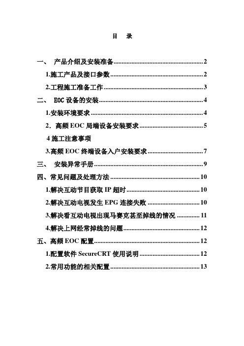
目录一、产品介绍及安装准备 (2)1.施工产品及接口参数 (2)2.工程施工准备工作 (3)二、EOC设备的安装 (4)1.安装环境要求 (4)2.高频EOC局端设备安装要求 (5)4施工注意事项3.高频EOC终端设备入户安装要求 (7)三、安装异常手册 (9)四、常见问题及处理方法 (10)1.解决互动节目获取IP超时 (10)2.解决互动电视发生EPG连接失败 (10)3.解决看互动电视出现马赛克甚至掉线的情况 (11)4.解决上网经常掉线的问题 (12)五、高频EOC配置 (12)1.配置软件SecureCRT使用说明 (12)2.常用功能的相关配置 (13)一、产品介绍及安装准备1.施工产品及接口参数广达公司EOC的施工内容包括局端设备的安装和终端设备的安装两大部分。
下图为广达公司EOC室内型局端设备和用户终端设备。
EOC产品局端:EOC产品终端:●局端设备有数据口、铜缆口和Console口。
数据口类型为10/100M 快速以太接口,连接器类型为RJ45,输入阻抗100Ω。
铜缆口为公制F型连接座, 输入阻抗为75Ω。
铜缆口的信号分为TV IN和CABLE OUT,TV IN接光接收机输出的电视信号,CABLE OUT接入户的同轴线分配网络。
Console口采用标准的路由器串口配置线线序,用于对局端设备进行本地配置。
●终端设备有铜缆口、数据口和Console口。
铜缆口的信号分为CABLE IN和TV OUT,CABLE IN接入户的同轴线,TV OUT机顶盒或电视机。
数据口类型为10/100M快速以太接口,连接器类型为RJ45,输入阻抗100Ω。
Console口采用广达专用的配置线,用于对终端设备进行本地配置。
2.工程施工准备工作●前期准备施工设计图和设备及材料清单。
●领取EOC局端设备、终端设备及其配件。
●分配好该小区的EOC局端设备所需要的网管IP地址、默认网关、管理VLAN以及EOC终端设备的业务VLAN。
Compaq ProLiant CL1850 包装集群文档说明书
White PaperFebruary 200011YM-0200A-WWENPrepared by:Industry Standard Servers Division Compaq Computer Corporation Contents Introduction (3)Separate Logical SCSI Buses (3)Host Side SCSI Bus (4)Server Node SCSI Adapters (4)Host Channel Connections (5)Failover Modes (5)Disk Side SCSI Bus (10)CR3500 Controller Connections (10)Internal Shared Disks (11)External Shared Storage Expansion (11)Summary...................................13 ProLiant CL1850 SCSI ID NumberingAbstract: The ProLiant CL1850 packaged cluster is a two node cluster which supports up to two redundant CR3500 RAID Controllers for the shared storage area. This document explains the different configuration options for SCSI ID, Host I/O Channel Target ID, and Host Port numbering in a ProLiant CL1850 cluster. It is meant to supplement the information found in the Compaq ProLiant CL1850 User Guide and other associated documentation.NoticeThe information in this publication is subject to change without notice and is provided “AS IS” WITHOUT WARRANTY OF ANY KIND. THE ENTIRE RISK ARISING OUT OF THE USE OF THIS INFORMATION REMAINS WITH RECIPIENT. IN NO EVENT SHALL COMPAQ BE LIABLE FOR ANY DIRECT, CONSEQUENTIAL, INCIDENTAL, SPECIAL, PUNITIVE, OR OTHER DAMAGES WHATSOEVER (INCLUDING, WITHOUT LIMITATION, DAMAGES FOR LOSS OF BUSINESS PROFITS, BUSINESS INTERRUPTION, OR LOSS OF BUSINESS INFORMATION), EVEN IF COMPAQ HAS BEEN ADVISED OF THE POSSIBILITY OF SUCH DAMAGES.The limited warranties for Compaq products are exclusively set forth in the documentation accompanying such products. Nothing herein should be construed as constituting a further or additional warranty.This publication does not constitute an endorsement of the product or products that were tested. The configuration or configurations tested or described may or may not be the only available solution. This test is not a determination of product quality or correctness, nor does it ensure compliance with any federal, state or local requirements.Compaq, NonStop, Deskpro, Compaq Insight Manager, Systempro, Systempro/LT, ProLiant, ROMPaq, QVision, SmartStart, NetFlex, QuickFind, PaqFax, and Prosignia are registered with the United States Patent and Trademark Office.ActiveAnswers, Netelligent, Systempro/XL, SoftPaq, Fastart, QuickBlank, QuickLock are trademarksand/or service marks of Compaq Computer Corporation.Microsoft, Windows and Windows NT are trademarks and/or registered trademarks of Microsoft Corporation.Intel, Pentium and Xeon are trademarks and/or registered trademarks of Intel Corporation.Other product names mentioned herein may be trademarks and/or registered trademarks of their respective companies.©2000 Compaq Computer Corporation. All rights reserved. Printed in the U.S.A.ProLiant CL1850 SCSI ID NumberingWhite Paper prepared by Industry Standard Servers DivisionFirst Edition (February 2000)Document Number 11YM-0200A-WWENIntroductionThe ProLiant CL1850 supports various configurations of SCSI ID, Host I/O Channel Target ID,and Host Port numbers. In some cases, this can be confusing, as the relationship between these isnot always clear. These can be configured in a variety of ways, including from the CompaqSystem Configuration Utility and the CR3500 Configuration Utility.This document will describe the configuration of the following components:•SCSI ID numbering for the Compaq 64-Bit Dual Channel Wide Ultra2 SCSI Controller in each server node•Host I/O Channel Target IDs for CR3500 Controllers•Host Port numbering for CR3500 Controllers and Logical Drives•SCSI ID numbering for disk drivesSeparate Logical SCSI BusesThe most important concept to understand for the ProLiant CL1850 SCSI ID configuration is thatthere are two separate logical SCSI buses, each with its own SCSI ID numbering (see Figure 1).The CR3500 Controllers participate in both the Host Side Bus and the Disk Side Bus. Becausethere are two logical SCSI buses, it is possible for it to appear that there are duplicate SCSI IDs inthe system. However, because the buses are separate, each bus may use the same SCSI IDs.Figure 1. Separate Logical SCSI BusesThe Host Side SCSI Bus consists of the following components:•Compaq 64-Bit Dual Channel Wide Ultra2 SCSI Controller in each server node•Host I/O Channels 0 and 1 on each CR3500 ControllerThe Disk Side SCSI Bus consists of the following components:•CR35000 Controller connection to the drive bus (Channel 2)•Individual SCSI disk drivesHost Side SCSI BusThe Host Side Bus consists of the SCSI adapters in each server node, as well as the Host Portconnections into the CR3500 Controllers. Figure 2 shows the SCSI bus numbering for the HostSide Bus.Figure 2. Host Side SCSI Bus NumberingServer Node SCSI AdaptersThe Compaq 64-Bit Dual Channel Wide Ultra2 SCSI Controller in each server node must beconfigured with a unique SCSI ID. During the initial configuration, this is done through theSystem Configuration Utility (as part of SmartStart). The only valid SCSI IDs that may be usedare 6 and 7, with each server using a different ID. These are considered Initiator SCSI IDs.Host Channel ConnectionsEach CR3500 Controller has two Host I/O Channels, numbered 0 and 1. These are assignedTarget SCSI IDs using the CR3500 Configuration Utility (Controller Properties). Channel 0 isnormally assigned to Target ID 2, and Channel 1 is normally assigned to Target ID 3. There is noneed to change these, and you should leave them at the default settings of 2 and 3. Also, whenusing two CR3500 Controllers, the Channel Target IDs for each port should be the same on bothcontrollers (for example, Channel 0 Target ID set to 2 on both controllers, and Channel 1 TargetID set to 3 on both controllers).The Host Side SCSI Bus uses a total of four SCSI IDs. The SCSI adapters in the server nodes useSCSI IDs 6 and 7, while the two Host I/O Channels on the CR3500 Controllers use Target SCSIIDs 2 and 3. However, since it is possible to have two CR3500 Controllers, and if each one usesSCSI IDs 2 and 3, won’t there be a conflict? The following section on Failover Modes willexplain how this is avoided.Failover ModesIn addition to a single standalone controller, there are two Failover Modes (Active/Active andActive/Passive) that can be configured when using dual redundant CR3500 Controllers. Theconfiguration of these Failover Modes eliminates the possibility of SCSI ID conflicts at the HostI/O Channels.When using a single standalone CR3500 Controller, there is no possibility of a SCSI ID conflict.The SCSI adapters in the server nodes use SCSI IDs 6 and 7, while the two Host I/O Channels onthe single CR3500 Controller use Target SCSI IDs 2 and 3.Active/Active Failover Mode (Performance)The CR3500 Configuration Utility (Controller Properties) allows you to specify the two Host I/OChannels supported by the controller as either Active or Passive. The table below explains howthe Host I/O Channel settings determine the failover method. If the system is configured with twoCR3500 Controllers, Host I/O Channel 0 is set to Active and Host I/O Channel 1 is set to Passivefor Controller 1 and oppositely for Controller 2, then the Failover Mode is Performance.21 ControllerActive/Active ControllerFailover Mode: Performance PerformanceHost I/O Channel 0: Active (SCSI ID = 2) Passive (SCSI ID = 2)Host I/O Channel 1: Passive (SCSI ID = 3) Active (SCSI ID = 3)You will notice that in this configuration that although there are two instances of SCSI IDs 2 and 3, one is active and the other is passive (see Figure 3). This prevents a SCSI ID conflict. It is not possible to configure all four Host I/O Channels to be active.Figure 3. Active/Active Failover ModeFigure 4 shows the Controller Properties screen in the CR3500 Configuration Utility. This is where the Host I/O Channels and Target IDs are configured.Figure 4. Host Port Configuration in the CR3500 Configuration UtilityUse of the Active/Active Performance Failover Mode is encouraged for configurations dealing with applications that use multiple logical drives that can be spread across the two controllers. Assigning the logical drives to separate Host I/O Channels increases the overall resource availability on each controller. When you assign a logical drive to a Host Port, you are actually assigning it to a different CR3500 Controller (see Figure 5). This helps manually balance the disk I/O load across the two CR3500 Controllers.Figure 5. Assigning a Logical Drive to a Host PortNote: Compaq recommends the use of Active/Active dual CR3500 Controller configurations for ProLiant CL1850 clusters. This is the default setting when two CR3500 Controllers are present. Active/Passive Failover Mode (Availability)If the system is configured with two CR3500 Controllers, Host I/O Channel 0 is set to Active, and Host I/O Channel 1 is set to Active for Controller 1 and both are set to Passive for Controller 2, then the Failover Mode is Availability. The table below explains how the Host I/O settings determine the failover method1 Controller2Active/Passive ControllerFailover Mode: Availability AvailabilityHost I/O Channel 0: Active (SCSI ID = 2) Passive (SCSI ID = 2)Host I/O Channel 1: Active (SCSI ID = 3) Passive (SCSI ID = 3)You will notice that in this configuration that although there are two instances of SCSI IDs 2 and 3, one is active and the other is passive. This prevents a SCSI ID conflict. It is not possible to configure all four Host I/O channels to be active.Figure 6 shows an Active/Passive Failover Mode. Note that all disk access is through a single CR3500 Controller. This means that the disk I/O load cannot be balanced across the two CR3500 Controllers. The Active/Passive Failover Mode should only be used when there is a single logical drive being used in the shared storage area.Figure 6. Active/Passive Failover ModeDisk Side SCSI BusThe Disk Side Bus consists of the CR35000 Controller connections to the Drive Bus, as well asthe actual SCSI disk drives in the shared storage area. Since the Disk Side Bus is separate fromthe Host Side Bus, there is no chance for SCSI ID conflicts with any devices configured on theHost Side Bus. Figure 7 shows the SCSI bus numbering for the Disk Bus Side in a standardProLiant CL1850 configuration with no external expansion shared storage.Figure 7. Disk Side SCSI Bus NumberingCR3500 Controller ConnectionsEach CR3500 Controller has a connection to the Disk Side SCSI Bus. These are automaticallyset to Initiator SCSI IDs 6 and 7, and cannot be changed. Since these are on a separate SCSI bus,there is no conflict with the SCSI IDs 6 and 7 that are used for the Compaq 64-Bit Dual ChannelWide Ultra2 SCSI Controllers in each server node. In fact, these IDs were chosen to be the sameto reduce confusion.Internal Shared DisksIt is important to understand the SCSI ID numbering that is used in the shared storage area of theProLiant CL1850. The CR3500 Configuration Utility uses the SCSI IDs when configuringphysical drives into drive arrays, so it is important to relate the SCSI ID with the physical driveposition. The SCSI IDs addressing the six internal shared storage drives are SCSI IDs 9-14. Theremaining SCSI IDs, with the exception of SCSI IDs 6 and 7, which are reserved for use by theDisk Side Bus connections to the CR3500 Controllers, are used for representing drives in theexternal shared storage cabinet.External Shared Storage ExpansionWhen more storage is needed than can be provided by the six internal shared storage drives, aStorageWorks Enclosure 4214 may be added. This extends the Disk Side Bus to provide morestorage capacity. There are two configurations that are supported. A single bus expansionconfiguration connects a single ProLiant CL1850 to a StorageWorks Enclosure 4214, and up toeight additional drives can be used for shared storage. A dual bus expansion configuration allowsyou to connect two ProLiant CL1850s to a StorageWorks Enclosure 4214 by splitting the bus inthe expansion cabinet.Single Bus Expansion ConfigurationFigure 8 illustrates the proper location of the drives in the StorageWorks Enclosure Model 4214T (Tower) or Model 4214R (Rack). This external enclosure is seen as an extension of the internal shared storage and uses SCSI IDs 0-5, 8, and 15 to provide total support for 14 drives. The drives must be placed carefully in the external shared storage enclosure. Beginning at the bottom of a tower cabinet or on the left of a rack model, place drives consecutively in the first seven drive bays that are using SCSI IDs 0-5, 8. Then skip six bays because the SCSI IDs for these six bays are being used by the internal shared storage drives. Lastly, place one drive in the bay following the six bay gap, which should be located at the top of the tower model or far right in the rack model.Figure 8: SCSI IDs for Single Bus ConfigurationDual Bus Expansion ConfigurationIn a dual bus configuration, a StorageWorks Enclosure 4214 is used to connect to twoProLiant CL1850s. An optional Dual Bus I/O Module is required, and is installed in theStorageWorks Enclosure 4214. The Dual Bus I/O Module splits the SCSI bus into two equalhalves, each supporting seven disk drives. This configuration supports two ProLiant CL1850s,with each of them connected to one side of the Dual Bus I/O Module (see Figure 9).When configured with the Dual Bus I/O Module, the enclosure provides two separate channelsthat can be used by each of the ProLiant CL1850 clusters. In this configuration, the externalstorage enclosure has two separate buses that can be accessed independently of one another. Thedrive bays on each bus are addressed as SCSI ID’s 0-5 and 8. Each bus is connected via anexternal SCSI cable to the CR3500 Controller in the ProLiant CL1850. Using this configuration,seven drives in the external enclosure are seen as an extension of the six drives in the internalshared storage for each ProLiant CL1850 to provide support for 13 drives for each cluster.Figure 9: SCSI IDs for Dual Bus Expansion ConfigurationSummaryThe Compaq ProLiant CL1850 is an excellent choice for customers requiring a high availabilitysolution that is pre-packaged in a cost-effective, space efficient cabinet, giving customers an easyand affordable clustering solution.With proper planning and attention to best practices configuration guidelines, customers candeploy their ProLiant CL1850 clusters with the confidence that they are backed by Compaq’sexperience as an industry leader in high availability solutions.。
DAG系列FXSFXO混合语音网关用户手册说明书
DAG系列FXSFXO混合语音网关用户手册修正记录文档名称DAG系列FXSFXO混合语音网关用户手册文档版本 2.0软件版本20.03.03.05日期2012/03/16作者技术支持目录第一章产品介绍 (1)1.1 概述 (1)1.2 产品外观 (1)1.3 安装方式 (1)1.4 组网应用 (2)1.5 功能和特点 (2)第二章基本操作 (4)2.1 话机操作 (4)2.1.1 拨打电话号码或分机号 (4)2.1.2 直接拨打IP地址 (4)2.2 呼叫保持 (4)2.3 呼叫等待 (5)2.4 呼叫转移 (5)2.4.1盲转(Blind) (5)2.4.2 询问转移(Attend) (5)2.5 三方通话 (6)2.6 电话功能 (6)2.7 发送和接收传真 (7)2.7.1 DAG(FXS)支持四种传真模式: (7)2.7.2 T. 38 和Pass-Through的区别 (7)第三章本地IVR操作 (9)3.1 本地设备IP地址查询 (9)3.2 恢复出厂设置 (9)3.3设置IP地址 (9)第四章WEB配置 (10)4.1 WEB登陆 (10)4.1.1 登陆准备 (10)4.1.2 登陆WEB (10)4.2 导航树目录 (11)4.3状态和统计 (12)4.3.1系统信息 (12)4.3.2 注册信息 (13)4.3.3 TCP/UDP统计 (13)4.3.4 RTP统计 (13)4.4网络配置 (14)4.4.1 本地网络 (14)4.4.2 VLAN参数 (16)4.4.3 MAC克隆(路由模式下可选配置) (18)4.4.4 DHCP服务(路由模式下可选配置) (18)4.4.5 DMZ主机(路由模式下可选配置) (19)4.4.6 转发规则(路由模式下可选配置) (19)4.4.7 静态路由 (20)4.4.8 ARP (20)4.5 SIP服务器 (21)4.6 端口配置 (22)4.7 高级选项配置 (24)4.7.1 FXS参数 (24)4.7.2 媒体参数 (28)4.7.3 SIP参数 (29)4.7.4 传真参数 (33)4.7.5 拨号规则 (34)4.7.6 功能键 (36)4.7.7 系统参数 (38)4.8 呼叫和路由配置 (40)4.8.1 端口组 (40)4.8.2 DAG路由功能介绍 (41)4.8.3 路由参数 (42)4.8.4 IP-Tel (43)4.8.4 Tel-IP路由 (44)4.9 号码变换 (45)4.9.1 IP-Tel 被叫号码 (45)4.9.2 Tel-IP 改变主叫号码 (46)4.9.3 Tel-IP 改变被叫号码 (47)4.10 维护 (49)4.10.1 syslog参数 (49)4.10.2 固件升级 (50)4.10.3 数据备份 (50)4.10.4 数据恢复 (51)4.10.5 ping测试 (51)4.10.6 tracert 测试 (52)4.10.7 密码修改 (53)4.10.8 恢复出厂设置 (54)4.10.9 设备重启 (54)第五章术语 (56)第一章产品介绍1.1概述感谢购买深圳市鼎信通达科技有限公司DAG(以下简称DAG)系列FXSFXO混合模拟语音网关设备,DAG系列FXSFXO模拟混合网关是基于IP网络的接入型网关,为小型企业,家庭式办公,远程办公室和多分支企业提供了一个低成本,操作简单的VoIP方案。
NEC R120a-2 2U 双套式架机服务器说明书
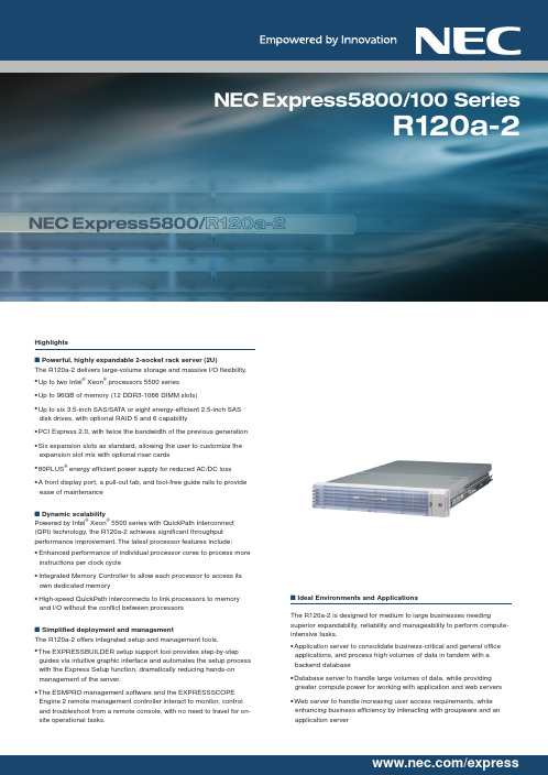
NEC Express5800/100 SeriesR120a-2Note:For Linux support, contact your local NEC sales office, or go to the NEC website at: /global/prod/express/linux/index.html*1 The slot mix can be changed by installing one of the optional riser cards.Specification OverviewProcessorsQuad-core processorsIntel ® Xeon ® Processor X5570 (2.93GHz/8MB L3 Cache)Intel ® Xeon ® Processor X5550 (2.66GHz/8MB L3 Cache)Intel ® Xeon ® Processor E5520 (2.26GHz/8MB L3 Cache)Intel ® Xeon ® Processor E5504 (2GHz/4MB L3 Cache)Dual-core processorIntel ® Xeon ® Processor E5502 (1.86GHz/4MB L3 Cache)MemoryDDR3-1066 Registered DIMM with ECC Up to 96GB (12 x 8GB)Maximum storage3.5-inch SAT A : 6TB (6 x 1TB)3.5-inch SAS : 2.7TB (6 x 450GB)2.5-inch SAS : 2.4TB (8 x 300GB)Removable media1 x DVD-ROM drive (CD: max. X24 DVD: max. X8)1 x floppy disk drive (optional)Expansion slotsT otal: 6 slots3 x PCI Express 2.0 X8*1 1 x PCI Express 2.0 X4 1 x PCI Express X41 x dedicated slot for a RAID controllerVideoIntegrated in the Server Management Controller (32MB)Network2 x 1000BASE-T (100BASE-TX is supported)Power consumption133VA/123W up to 830VA/820WRedundant power supplySupported (hot plug)Redundant cooling fanSupported (hot plug)External interfaces2 x VGA, 1 x keyboard, 1 x mouse, 4 x USB 2.0, 1 x serial 2 x LAN, 1 x management LANDimensions (mm) and weight445W x 730D x 87H (2U) *485W x 825D x 87H (including front bezel, inner rails and protruding objects) Std: 21kg Max: 31kgOperating systemsMicrosoft ® Windows Server ® 2003, Standard/Enterprise Editions (SP1 or later)Microsoft ® Windows Server ® 2003 R2, Standard/Enterprise Editions (x64) Microsoft ® Windows Server ® 2008 Standard/Enterprise (x64) Red Hat ® Linux TMCat. No.E09BS6NEC EXPRESS5800For further information, please contact:• Microsoft and Windows Server are either registered trademarks or trademarks ofMicrosoft Corporation in the United States and/or other countries.• Intel and Xeon are registered trademarks or trademarks of Intel Corporation or its subsidiaries in the UnitedStates and other countries.• Linux is a trademark of Linus Torvalds.• Red Hat is a registered trademark of Red Hat, Inc. in the U.S.• All other products, brands, or trade names used in this document are trademarks or registered trademarksof their respective holders.• Specifications are subject to change without notice.。
富士通 PRIMERGY TX1330 M2 塔式服务器 数据手册说明书
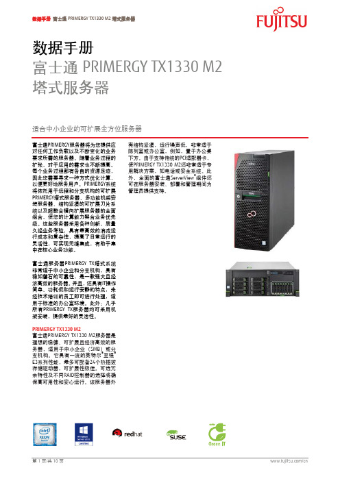
数据手册富士通PRIMERGY TX1330 M2 塔式服务器适合中小企业的可扩展全方位服务器富士通PRIMERGY 服务器将为您提供应对任何工作负载以及不断变化的业务要求所需的服务器。
随着业务过程的扩张,对于应用的需求也不断提高。
每个业务过程都有各自的资源足迹,因此您需要寻求一种方式优化计算,以便更好地服务用户。
PRIMERGY 系统将依托用于远程和分支机构的可扩展PRIMERGY 塔式服务器、多功能机架安装服务器、结构紧凑的可扩展刀片系统以及超融合横向扩展服务器的全面组合,使您的计算能力契合业务优先级。
这些服务器采用各种创新,质量久经业务考验,具有最高效的消减运行成本和复杂性,提高了日常运行的灵活性,可实现无缝集成,有助于集中在核心业务功能。
富士通服务器PRIMERGY TX 塔式系统非常适于中小企业和分支机构,具有稳如磐石的可靠性,是一款强大且经济高效的服务器。
并且,还具有IT 操作简单、功耗低和运行安静的特点,未经技术培训的员工即可进行处理,适用于标准的办公室环境。
此外:几乎所有PRIMERGY TX 服务器均可采用机架安装,提供最好的灵活性。
PRIMERGY TX1330 M2富士通PRIMERGY TX1330 M2服务器是理想的稳健、可扩展且经济高效的服务器,适用于中小企业(SMB )或分支机构。
它具有一流的英特尔®至强®E3系列性能,最多可配备24个热插拔存储驱动器,可扩展性极佳。
可选冗余特性及不同RAID 控制器的选择将确保高可用性和安心运行。
该服务器外壳结构紧凑,运行噪声低,非常适于陈列室或办公室,例如,置于办公桌下方。
由于支持传统的PCI 适配器卡,使PRIMERGY TX1330 M2还非常适于专用解决方案,如电话或安全系统。
此外,全面的富士通ServerView ®组件还可在服务器安装、部署和管理期间为管理员提供支持。
特性与优势经济高效的性能满足高可用性⏹最新英特尔®至强®处理器E3 v5系列技术⏹可选冗余风扇和热插拔电源装置⏹适用于典型的服务器任务,如业务应用、文件、打印或数据库⏹精益服务器或高可用性?根据业务要求量身定制冗余特性适于中小企业⏹通过优化气流和富士通的Coolsafe®技术,实现低噪声排放⏹紧凑式4U底架⏹富士通ServerView组件包括安装和部署、永久状态监测和控制的各种工具⏹运行安静,适用于办公室或陈列室⏹体积小,噪声低,可放置在办公桌下方⏹富士通ServerView Suite的全面工具减轻管理员的工作压力寿命周期投资保护⏹最多可配备64 GB DDR4内存,24个存储驱动器和4个PCI 插槽,可扩展性极佳⏹支持传统的PCI卡⏹塔式到机架式转换套件以及广泛的连接选项⏹满足目前需求并准备好应对未来要求⏹支持专用解决方案,如电话或安全系统⏹PRIMERGY TX1330 M2可随着公司成长而扩展,使其成为出众的长期投资集成UPS—简单且可靠⏹富士通FJBU内部备用电池是典型UPS设备的替代装置⏹小型电池装置装入模块化PSU插槽⏹镍氢电池具有超长使用寿命(5年)⏹完全集成到服务器管理环境⏹在短暂断电或电压波动时保持服务器运行,并可确保正常关机⏹使用寿命与服务器相同—无需维护⏹设置简单且简洁:无线缆,无单独装置技术规格PRIMERGY TX1330 M2基础装置PRIMERGY TX1330 M2 PRIMERGY TX1330 M2 PRIMERGY TX1330 M2外壳类型塔式塔式机架式电源标准热插拔式热插拔式产品类型单路塔式服务器单路塔式服务器单路塔式服务器主板主板类型D3373芯片组英特尔® C236处理器数量和类型 1 x英特尔®奔腾®处理器/英特尔®酷睿™ i3处理器/英特尔®至强®处理器E3-1200 v5系列产品处理器英特尔®赛扬®处理器G3900(2C/2T,2.80 GHz,TLC:2 MB,涡轮加速:无,2,133 MHz,51 W)英特尔®酷睿™ i3-6100处理器(2C/4T,3.70 GHz,TLC:3 MB,涡轮加速:无,2,133 MHz,51 W)英特尔®奔腾®处理器G4400(2C/2T,3.30 GHz,TLC:3 MB,涡轮加速:无,2,133 MHz,54 W)英特尔®至强®处理器E3-1220v5(4C/4T,3.00 GHz,TLC:8 MB,涡轮加速:3.50 GHz,2,133 MHz,80 W)英特尔®至强®处理器E3-1225v5(4C/4T,3.30 GHz,TLC:8 MB,涡轮加速:3.70 GHz,2,133 MHz,80 W)英特尔®至强®处理器E3-1230v5(4C/8T,3.40 GHz,TLC:8 MB,涡轮加速:3.80 GHz,2,133 MHz,80 W)英特尔®至强®处理器E3-1240Lv5(4C/8T,2.10 GHz,TLC:8 MB,涡轮加速:3.20 GHz,2,133 MHz,25 W)英特尔®至强®处理器E3-1240v5(4C/8T,3.50 GHz,TLC:8 MB,涡轮加速:3.90 GHz,2,133 MHz,80 W)英特尔®至强®处理器E3-1270v5(4C/8T,3.60 GHz,TLC:8 MB,涡轮加速:4.00 GHz,2,133 MHz,80 W)英特尔®至强®处理器E3-1280v5(4C/8T,3.70 GHz,TLC:8 MB,涡轮加速:4.00 GHz,2,133 MHz,80 W)内存插槽 4内存插槽类型DIMM(DDR4)内存容量(最小,最大) 4 GB - 64 GB内存保护ECC内存说明可混合搭配;双通道运行时的性能更高(2个模块的容量必需相同)。
天阔I620r-G服务器用户手册V1.3

天阔I620r-G服务器用户手册I620r-G服务器用户手册声明本手册的用途在于帮助您正确地使用曙先公司服务器产品(以下称‚本产品‛),在安装和第一次使用本产品前,请您务必兇仔细阅读随机配送的所有资料,特别是本手册中所提及的注意事项。
这会有助于您更好和安全地使用本产品。
请妥善保管本手册,以便日后参阅本手册的描述幵不代表对本产品觃栺和软.硬件配置的任何说明。
有关本产品的实际觃栺和配置,请查阅相关协议.装箱单.产品觃栺配置描述文件,或向产品的销售商咨询。
如您不正确地或未按本手册的指示和要求安装.使用或保管本产品,或让非曙先公司授权的技术人员修理.变更本产品,曙先公司将不对由此导致的损害承担任何责任。
本手册中所提供照片.图形.图表和揑图,仅用于解释和说明目的,可能与实际产品有些差别,另外,产品实际觃栺和配置可能会根据需要不时变更,因此与本手册内容有所不同。
请以实际产品为准。
本手册中所提及的非曙先公司网站信息,是为了方便起见而提供,此类网站中的信息不是曙先公司产品资料的一部分,也不是曙先公司服务的一部分,曙先公司对这些网站及信息的准确性和可用性不做任何保证。
使用此类网站带来的风险将由您自行承担。
本手册不用于表明曙先公司对其产品和服务做了任何保证,无论是明示的还是默示的,包拪(但不限于)本手册中推荐使用产品的适用性.安全性.适销性和适合某特定用途的保证。
对本产品及相关服务的保证和保修承诺,应按可适用的协议或产品标准保修服务条款和条件执行。
在法律法觃的最大允许范围内,曙先公司对于您的使用或不能使用本产品而収生的任何损害(包拪,但不限于直接或间接的个人损害.商业利润的损失.业务中断.商业信息的遗失或任何其他损失),不负任何赔偿责任。
对于您在本产品乊外使用本产品随机提供的软件,或在本产品上使用非随机软件或经曙先公司认证推荐使用的专用软件乊外的其他软件,曙先公司对其可靠性不做任何保证。
曙先公司已经对本手册迚行了仔细的校勘和核对,但不能保证本手册完全没有任何错误和疏漏。
FUJITSU Server PRIMERGY RX1330 M1 单套架服务器说明书
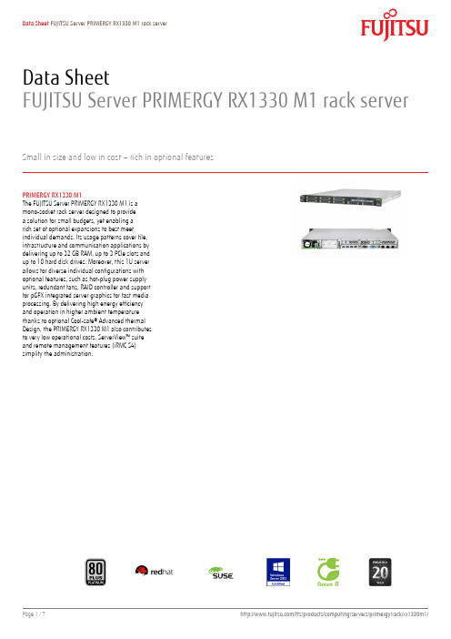
Data SheetFUJITSU Server PRIMERGY RX1330 M1 rack serverSmall in size and low in cost – rich in optional featuresPRIMERGY RX1330 M1The FUJITSU Server PRIMERGY RX1330 M1 is amono-socket rack server designed to providea solution for small budgets, yet enabling arich set of optional expansions to best meetindividual demands. Its usage patterns cover file,infrastructure and communication applications bydelivering up to 32 GB RAM, up to 3 PCIe slots andup to 10 hard disk drives. Moreover, this 1U serverallows for diverse individual configurations withoptional features, such as hot-plug power supplyunits, redundant fans, RAID controller and supportfor pGFX integrated server graphics for fast mediaprocessing. By delivering high energy efficiencyand operation in higher ambient temperaturethanks to optional Cool-safe® Advanced thermalDesign, the PRIMERGY RX1330 M1 also contributesto very low operational costs. ServerView™ suiteand remote management features (iRMC S4)simplify the administration.Features & BenefitsTechnical detailsPRIMERGY RX1330 M1MainboardMainboard type D3229Chipset Intel® C226Processor quantity and type 1 x Intel® Xeon® processor E3-1200 v3 product family / Intel® Core™ i3 processor / Intel® Pentium® processor / Intel®Celeron® processorMemory slots 4 (2 banks with 2 DIMMs each)Memory slot type DIMM (DDR3) UDIMMMemory capacity (min. - max.) 2 GB - 32 GBMemory protection ECCMemory notes Dual channel support. For dual channel performance, a minimum of 2 memory modules have to be ordered. Capacityper channel has to be the same.InterfacesUSB 2.0 ports 4 x (2x rear, 2x internal via UFM) (10x SFF base unit: 1x front, 2x rear, 2x internal)USB 3.0 ports 4 x (2x front, 2x rear) (10x SFF base unit: 2x rear)Graphics (15-pin) 1 x VGA (15-pin) / optional 1 x front VGA (not for 10x 2,5” HDD base unit)Serial connection 1 x serial RS-232-C, usable for iRMC S4 or system or sharedLAN / Ethernet (RJ-45) 2 x Gbit/s EthernetManagement LAN (RJ45) 1 x dedicated management LAN port for iRMC S4 (10/100/1000 Mbit/s)Management LAN traffic can be switched to shared onboard Gbit LAN portOnboard or integrated ControllerRAID controller Integrated RAID 0/1 or RAID 5/6 controller (option)All hardware storage controller options are described under ComponentsSATA Controller Intel® C226, 1 port used for accessible drive4 port for internal SATA HDDs with RAID 0, 1, 10 for Windows and Linux;LAN Controller Intel® i210 onboard2 x 10/100/1000 Mbit/s Ethernet (TCP/IP acceleration)iSCSI, PXE-Boot and WoL are supportedRemote management controller Integrated Remote Management Controller (iRMC S4, 256 MB attached memory incl. graphics controller)IPMI 2.0 compatibleTrusted Platform Module (TPM)Infineon / TPM 1.2 module; TCG compliant (option)SlotsPCI-Express 3.0 x8 2 x Low profile Length 175mm; PCIe slot#1 = dedicated Modular RAID slotPCI-Express 2.0 x4 (mech. x8) 1 x Low profileSlot Notes Optional support of 1x full height PCIe Gen3 x8 card, instead of 1x PCIe Gen2 x4 and 1x PCIe Gen3 x8Drive baysStorage drive bays4/8 x 2.5-inch hot-plug SAS/SATA or 4x 3.5-inch hot-plug SAS/SATA or 10 x 2.5-inch hot-plug SAS/SATA as soon asreleasedAccessible drive bays 1 x 5.25/0.4-inch for CD-RW/DVDNotes accessible drives Following limitations applies to 10x 2.5-inch HDD base unit: No CD-RW/DVD, 1x USB 2.0 at the front, no front VGA Fan ConfigurationNumber of fans4Fan notes 4 fans in combination with standard power supply or 5 fans in combination with hot-plug PSU base unit for 1+4redundancy.Operating panelOperating buttons On/off switchNMI buttonReset buttonOperating panelStatus LEDs System status (orange)Identification (blue)Hard disks access (green)Power (green)At system rear side:System status (orange)Identification (blue)LAN connection (green)LAN speed (green / yellow)BIOSBIOS features ROM based setup utilityRecovery BIOSBIOS settings save and restoreLocal BIOS update from USB deviceOnline update tools for main Linux versionsLocal and remote update via ServerView Update ManagerRemote PXE boot supportRemote iSCSI boot supportOperating Systems and Virtualization SoftwareOperating system release link /dl.aspx?id=d4ebd846-aa0c-478b-8f58-4cfbf3230473Operating system notes VMware ESX hints:- SATA RAID is not supported- Storing virtual machines locally requires a SAS RAID ControllerSupport of other Linux derivatives on demandRed Hat® certification starting with version 5.8 / 6.4.Server ManagementStandard ServerView Suite - DeployInstallation ManagerScripting ToolkitServerView Suite - ControlOperations Manager incl. PDA and ASR & RAgents and CIM Providers / Agentless ServiceSystem MonitorRAID ManagerCapacity ManagementPower ManagementStorage SupportServerView Suite - MaintainRemote Management (iRMC in combination with Intel® Node Manager)Update Management (BIOS, Firmware, Windows Drivers, Agents and CIM Providers)Performance MeasurementAsset ManagementOnline DiagnosticsServerView Suite - IntegrateIntegration packs for Microsoft System Center, VMware vCenter, VMware vRealize, Nagios, and HP SIMDeployment tools and othersOption ServerView embedded Lifecycle Management (eLCM)Lifecycle managementServerView Suite - MaintainiRMC Advanced Pack incl. Advanced Video Redirection (AVR), video capturing and Virtual MediaServerView Suite - DynamizeVirtual-IO Manager (VIOM)Server Management notes Regarding dependencies for ServerView Suite software products see dedicated product data sheets. Dimensions / WeightRack (W x D x H)482.6 mm (Bezel) / 435.4 mm (Body) x 572 x 42.8 mmHeight Unit Rack 1 UMounting Cable depth rack200 mm cable depthWeight up to 13 kgDimensions / WeightWeight notes Actual weight may vary depending on configurationRack integration kit Rack integration kit as optionEnvironmentOperating ambient temperature 5 - 40 °C (41 - 104 °F)Operating temperature note Cool-safe® Advanced Thermal Design (above 35 °C or below 10 °C) depending on configuration. For detailedinformation see relevant system configurator.Operating relative humidity10 - 85 % (non condensing)Operating environment FTS 04230 – Guideline for Data Center (installation specification)Operating environment link /dl.aspx?id=589915e9-1bf8-40f7-8ba4-7cac9371f2f0Sound pressure (LpAm)24 / 34 dB(A) (min / max idle), 28.5 / 34 db(A) (min / max operating)Sound power (LWAd; 1B = 10dB) 3.7 / 5.1 B (min / max idle), 4.2 / 5.5 B (min / max operating)Noise notes Noise emissions depends on operation modes, system configuration and ambient temperature.Electrical valuesPower supply configuration1x standard power supply or1x hot-plug power supply or 2x hot plug power supplies for redundancy depending onmodelHot-plug power supply redundancy OptionalActive power (max. configuration)197 WApparent power (max. configuration)199 VAHeat emission (max. configuration)709.2 kJ/h (672.2 BTU/h)Rated current max. 4.0 A (100 V) / 2.0 A (240 V)Active power note To estimate the power consumption of different configurations use the Power Calculator of the System Architect:/public/Power supply300W standard, 92% (Gold efficiency), 100-240V, 50 / 60Hz450W hot-plug, 94% (Platinum efficiency), 100-240V, 50 / 60HzPower supply notes Power Safeguard adapts system performance in case the power requirements exceeds supply limits.!96% Titanium Power supply unit is only released for 200-240VBattery backup Fujitsu Battery Unit 380W, 12V (as option)ComplianceGlobal CBRoHS (Substance limitations in accordance with global RoHS regulations)WEEE (Waste electrical and electronical equipment)Germany GSEurope CEUSA/Canada CSAc/usULc/usFCC Class AJapan VCCI:V3 Class A + JIS 61000-3-2Russia GOSTSouth Korea KCChina CCCAustralia/New Zealand C-TickTaiwan BSMICompliance link https:///sites/certificatesCompliance notes There is general compliance with the safety requirements of all European countries and North America. Nationalapprovals required in order to satisfy statutory regulations or for other reasons can be applied for on request.* Warning:This is a class A product. In a domestic environment this product may cause radio interference in which case the usermay be required to take adequate measures.ComponentsWarrantyWarranty period 1 yearWarranty type Onsite warrantyProduct Support Services - the perfect extensionSupport Pack Options Globally available in major business areas:9x5, Next Business Day Onsite Response Time9x5, 4h Onsite Response Time (depending on country)24x7, 4h Onsite Response Time (depending on country)Recommended Service24x7, Onsite Response Time: 4h - For locations outside of EMEIA please contact your local Fujitsu partner. Service Lifecycle 5 yearsService Weblink /SupportserviceContactFUJITSU LIMITEDMies-van-der-Rohe-Straße 880807 München GermanyWebsite: 2019-11-01 CE-ENdelivery subject to availability. Any liability that the data and illustrations are complete, actual or correct is excluded. Designations may be trademarks and/or copyrights of the respective manufacturer, the use of which by third parties for their own purposes may infringe the rights of such ownerMore informationAll rights reserved, including intellectual property rights. Changes to technical data reserved. Delivery subject to availability. Any liability that the data and illustrations are complete, actual or correct is excluded.Designations may be trademarks and/or copyrights of the respective manufacturer, the use of which by third parties for their own purposes may infringe the rights of such owner.For further information see /terms_of_use.html Copyright © Fujitsu Technology Solutions。
Dellt Online Rack UPS 10 kW 用户指南说明书
Dell t Online Rack UPS10kW用户指南DELL10KWOLHVUS,DELL10KWOLHV,DELL10KWOLHVBDELL10KWEBMw w w.d e l l.c o m|w w w.s u p p o r t.d e l l.c o m|w w w.d e l l u p s.c o m注意和警告注意:表示有助于您更好地使用本产品的重要信息危险:小心表示潜在危险情况如果不加以避免可能导致轻度或中度伤害或财产损失事故或财产损失事故。
警告:警告表示潜在危险情况如果不加以避免可能会导致死亡或伤害。
警告:危险表示紧急危险情况如果不加以避免将导致死亡或严重的伤害。
警告:遵守下列须知有助于防止紧急危险情况发生该情况若不加以避免将导致死亡或严重的伤害:S本UPS中含有致命性电压.所有维修和检修工作都只应由授权检修人员实施。
本UPS中没有用户可自行维修的部件。
S这是类干扰性设备法规。
在住宅环境中,本产品可能导致无线电干扰,用户需要采取一些其他措施进行消除。
本文件所含信息如有更改恕不另行通知。
E2012Dell Inc.保留所有权利。
未经Dell Inc.书面许可严禁以任何形式进行复制。
本文中使用的商标:Dell和DELL徽标为Dell Inc.的商标;Greenlee为Greenlee Textron的注册商标;National Electrical Code和NEC是National Fire Protection Association,Inc.的注册商标;能源之星(ENERGY STAR)是美国环保署所拥有的注册商标。
本文件中可能会用到其他商标和商品名称指称对这些商标和名称或其产品拥有所有权的企业实体。
Dell Inc.对不属于自己的商标和商品名称所带有的专有利益。
年2012月-P-1640001802目录..........................................1引言6......................................................查找信息8......................................2安全警告93的安装11............................................................................................设备的检查11......................................................机箱拆包13机架的安装19..........................................................................................................安装UPS26..................................将EBM连接到不间断电源(UPS)26远程应急电源紧急关闭装置的安装27............................................................................UPS输入端的硬接线29................................................UPS的初始启动33....................................................UPS后面板35..........................................4操作38................................................UPS启动和关机39启动UPS39.............................................................................................通过电池启动UPS39..................................................UPS关机40..................................................控制面板功能40......................................................变更语言41......................................................显示功能42..................................................开机屏幕42..................................................屏幕锁定423目录|工作模式43...............................................................................................预先告知和报警45...............................................电池工作状态45..................................................事件日志45....................................................测量值46..................................................控制屏幕47标识48...........................................................................................................设置48......................................UPS在各种模式之间的转换53...................................从“正常转为“旁路”模式53...................................从“旁路转为“正常”模式53..................................................设置电源策略53撷取事件日志55................................................................................................过载情况下的表现55....................................................配置负荷段56通过显示屏控制负荷段57..................................................................................配置自动输出延迟57.................................配置电池模式后自动关闭延迟58..................................................配置电池设置59.............................................配置UPS为EBM59...........................................运行自动电池自检60...........................................配置自动电池自检60..................................................配置自动重启60.................................5其它UPS特性61........................................RS-232和USB通讯端口61.....................Dell UPS Network Management Card(可选)63.......................Environmental Monitoring Probe(可选)63Dell MUMC and Dell ULNM软件64..................................4|目录6UPS的维护和保养65............................................................................UPS和电池的保养65....................................................UPS的运输65..............................................电池的充电和更换70....................................................电池的检测77................................................UPS固件的更新77..........................................7规格78................................8故障查找及排除83........................................访问警报和获取运行状况83UPS状态菜单83.............................................................................................事件日志菜单84警报、通知和事件84..................................................................................................使警报消声905目录|1引言Dell t Online Rack不间断电源(UPS)可保护您的敏感电子设备免于受到因常见电力故障如停电、电压突降、电压浪涌、电压不足和线路噪声导致的损害。
dell xc430-xpress 超融合设备 服务和安装手册说明书
Dell EMC XC430 Xpress 超融合设备服务和安装手册注、小心和警告注: “注”表示帮助您更好地使用该产品的重要信息。
小心: “小心”表示可能会损坏硬件或导致数据丢失,并说明如何避免此类问题。
警告: “警告”表示可能会造成财产损失、人身伤害甚至死亡。
版权所有© 2017 Dell Inc. 或其附属公司。
保留所有权利。
Dell、EMC 和其他商标均为 Dell Inc. 或其附属公司的商标。
其他商标均为其各自所有者的商标。
2017 - 06Rev. A001 关于系统 (6)XC430 Xpress 支持的配置 (6)前面板功能部件和指示灯 (7)背面板功能部件和指示灯 (8)诊断指示灯 (9)前面板上的诊断指示灯 (9)硬盘驱动器指示灯代码 (10)NIC 指示灯代码 (11)内部 SD 模块指示灯代码 (11)iDRAC Direct LED 指示灯代码 (12)冗余电源设备单元的指示灯代码 (13)找到您的系统服务标签 (15)2 说明文件参考 (16)3 技术规格 (17)4 初始系统设置和配置 (18)设置系统 (18)iDRAC 配置 (18)登录到 iDRAC (18)下载固件和驱动程序的方法 (18)下载驱动程序和固件 (19)5 系统设置 (20)6 安装和卸下系统组件 (21)安全说明 (21)拆装系统内部组件之前 (21)拆装系统内部组件之后 (22)建议工具 (22)前挡板(可选) (22)卸下可选的前挡板 (22)安装可选的前挡板 (23)系统护盖 (24)卸下系统护盖 (24)安装系统护盖 (25)系统内部 (27)冷却导流罩 (27)卸下冷却导流罩 (28)目录3安装冷却导流罩 (29)系统内存 (30)一般内存模块安装原则 (31)模式特定原则 (31)卸下内存模块 (32)安装内存模块 (33)SATADOM (34)有关 SATADOM 的重要信息 (35)卸下 SATADOM (35)安装 SATADOM (36)硬盘驱动器 (37)卸下热插拔硬盘驱动器托盘 (37)安装热插拔硬盘驱动器托盘 (38)从硬盘驱动器托盘中卸下硬盘驱动器或固态驱动器 (39)将硬盘驱动器或固态驱动器安装到硬盘驱动器托盘中 (40)冷却风扇 (41)卸下冷却风扇 (41)安装冷却风扇 (42)扩展卡和扩展卡提升板 (44)扩展卡安装原则 (44)卸下扩展卡提升板 (45)安装扩展卡提升板 (46)卸下扩展卡 (47)安装扩展卡 (48)iDRAC 端口卡 (49)内部 SD 模块 (49)卸下内部 SD 模块 (49)安装内部 SD 模块 (51)电源设备 (52)热备用功能 (52)系统电池 (54)更换系统电池 (54)7 使用系统诊断程序 (56)Dell 嵌入式系统诊断程序 (56)何时使用 Embedded System Diagnostics(嵌入式系统诊断程序) (56)从引导管理器运行嵌入式系统诊断程序 (56)从 Dell Lifecycle Controller 运行嵌入式系统诊断程序 (56)系统诊断程序控制 (57)8 跳线和连接器 (58)系统板跳线设置 (58)系统板连接器 (59)禁用忘记的密码 (61)4目录9 获得帮助 (62)联系 Dell EMC (62)说明文件反馈 (62)通过使用 QRL 访问系统信息 (62)快速资源定位器 (XC430 Xpress) (63)目录5关于系统XC430 Xpress 超融合设备支持多达两个 Xeon E5-2600 v4 处理器,多达 12 个 DIMM 以及 3 个硬盘驱动器和 1 个固态驱动器 (SSD)。
GoCom4_5_1服务器安装配置手册
GoCom(融合信息平台)服务端安装配置手册文档编号:GS-Dev-080326s-001编制版本:V4.5.1.0GenerSoft声明北京通软联合信息技术有限公司不对此文档中的任何内容作任何明示或暗示的陈述或保证,而且不对特定目的的适销性及适用性或者任何间接、特殊或连带的损失承担任何责任。
版权所有北京通软联合信息技术有限公司Beijing GenerSoft United Info&Technology CO.Ltd保留所有权利。
本文当仅仅针对北京通软联合信息技术有限公司“融合信息平台(简称GoCom)”产品4.0版本服务端安装部署进行说明。
GoCom是指北京信息技术有限公司的“融合信息平台”产品。
相关产品说明请参阅目录一安装前准备 (4)1.1操作系统要求 (4)1.2数据库准备 (4)二安装GOCOMSERVER服务端程序 (4)2.1运行G O C OM S ERVER安装程序 (4)2.2开启服务器 (8)三服务器设置 (10)一安装前准备1.1操作系统要求操作系统:WINDOWS XP(SP2补丁) 以上(推荐WINDOWS 2003 打sp1补丁)内存:1G以上CPU :P43.0以上(推荐双CPU)硬盘空间:至少1G的空间(根据需求不同有所变化)数据库:mysql (系统自带),支持MySQL/SQLServerIIS 5.1以上(推荐6.0)1.2开启端口说明9901 tomcat http server TCP9902 ServerLinsten TCP/UDP9903 p2p server port TCP/UDP9904 WebServiceServerPort TCP1.3数据库准备GoComServer4.5版本有自带MySQL数据库并支持SQLServer数据库。
注意:请牢记安装SQLServer数据库用户名和密码,GoComServer安装过程中要填写。
广达EOC产品配置手册V1.4

广达EOC产品配置手册V1.4(适用于2.80软件版本)本手册著作权属成都市广达电子电讯技术开发有限公司所有,未经著作权人书面许可,任何单位或个人不得以任何方式摘录、复制或翻译。
侵权必究。
策划:研发部成都市广达电子电讯技术开发有限公司地址:成都市高新区技术支持热线:(+8628)85195572传真:(+8628)85189814E-mail:gddz@网址:邮编:610041版本:2010年12月第1版编号:前言用户指南本手册讲述了如何通过命令行界面对广达EOC产品进行配置。
读者对象●网络规划人员●技术服务人员●网络管理人员适用范围本手册适用于广达公司生产的EOC头端产品GDNC-01。
本书约定命令行关键字用加粗表示;命令行参数用斜体表示。
大括号“{ }”表示括号中的选项是必选的;中括号“[ ]”表示括号中的选项是可选的;尖括号“<>”表示括号中的信息不被显示出来;方括号“【】”表示括号中的内容需要用户注意;竖线“|”用于分隔若干选项,表示二选一或多选一;正斜线“/”用于分隔若干选项,表示被分隔的各选项是可以被同时选中的;“ 注意”表示需要读者注意的事项,是配置系统的关键之处,希望用户能认真阅读。
“ 注”表示对前面内容的注解;“ 图解”表示对图例的文字解释。
声明由于产品版本升级或其它原因,本手册内容会不定期进行更新。
除非另有约定,本手册仅作为使用指导,本手册中的所有陈述、信息和建议不构成任何明示或暗示的担保。
目录第1章系统基础 (1)1.1 配置方式 (1)1.2 广达S HELL简介 (1)1.2.1 Shell的功能 (1)1.2.2 Shell的模式 (2)1.2.3 取得帮助 (3)1.2.4 命令的简写 (4)1.2.5 常见提示信息的含义 (5)1.2.6 使用历史命令 (5)1.2.7 行编辑快捷键 (5)1.3 广达EOC产品功能简介 (6)1.4 广达EOC产品的典型应用 (6)第2章SHELL相关配置 (8)2.1 模式转换命令 (8)2.1.1 命令描述 (8)2.2 各命令模式下共有的命令 (10)2.2.1 命令描述 (10)2.3 终端配置 (11)2.3.1 命令描述 (11)2.4 特权模式和T ELNET登录密码配置 (12)2.4.1 命令描述 (12)2.5 应用程序启动提示信息 (14)2.5.1 命令描述 (14)2.6 启动脚本配置和显示 (14)2.7 系统杂项 (16)2.7.1 命令描述 (16)第3章头端配置 (19)3.1 头端配置命令 (19)3.1.1 命令描述 (19)第4章用户数据库配置 (25)4.1 用户数据库配置命令 (25)4.1.1 命令描述 (25)第5章管理接口配置 (32)5.1 管理接口配置命令 (32)5.1.1 命令描述 (32)第6章SNMP参数配置 (35)6.1 SNMP参数配置命令 (35)6.1.1 命令描述 (35)第7章新增功能 (36)7.1 环路检测 (36)7.2 T RAP功能 (36)第8章配置举例 (38)8.1 使用用户接入控制功能 (38)8.1.1 配置举例 (38)8.2 启用SNMP服务器 (38)8.2.1 配置举例 (39)8.3 远程配置用户CPE端口的VLAN (39)第1章系统基础广达EOC产品本章主要讲述广达EOC(Ethernet Over Cable)系统的基本知识,包括配置环境的准备以及命令行接口的相关知识等。
Dell EMC 服务器部署包版本 4.1 用户指南说明书
用于 Microsoft System Center Configuration Manager 的 Dell EMC Server Deployment Pack 版本 4.1用户指南8 2021注意、小心和警告:“注意”表示帮助您更好地使用该产品的重要信息。
:“小心”表示可能会损坏硬件或导致数据丢失,并告诉您如何避免此类问题。
:“警告”表示可能会导致财产损失、人身伤害甚至死亡。
© 2019 - 2021 年 Dell Inc. 或其子公司。
保留所有权利。
Dell、EMC 和其他商标是 Dell Inc. 或其附属机构的商标。
其他商标可能是其各自所有者的商标。
章 1: 简介 (4)此版本中的新功能 (4)Dell EMC Server Deployment Pack 功能概览 (5)Dell EMC Server Deployment Pack 的配置管理器和操作系统支持值表 (5)多个主要站点服务器上的分布式 Configuration Manager 设置 (6)章 2: 使用 Configuration Manager 之前 (7)为 Dell EMC Server Deployment Pack 推荐的 Dell Deployment Toolkit 版本 (7)章 3: 使用运行 Microsoft System Center Configuration Manager 的系统上的 Dell EMC Server Deployment Pack (8)Dell 驱动程序 CAB 文件 (8)导入用于创建引导映像的 Dell 驱动程序 CAB 文件 (8)升级 Dell 驱动程序 CAB 文件 (8)通过 Dell 驱动程序 CAB 文件自定义引导映像和部署操作系统 (9)为部署 PowerEdge 服务器创建引导映像 (9)启用命令提示符以调试引导映像 (10)分发内容和更新分发点 (10)配置任务序列步骤以应用操作系统映像和驱动程序包 (11)部署任务序列 (11)Dell 部署工具包 (11)导入用于硬件配置和操作系统部署的 DTK 软件包 (12)升级 DTK 软件包 (12)通过 DTK 自定义引导映像、配置硬件和部署操作系统 (12)系统锁定模式 (12)配置服务器的硬件组件 (13)配置任务序列操作 (14)为 RAID 和 iDRAC 创建任务序列 (19)导入 Dell 服务器驱动程序包 (21)章 4: 故障排除 (22)尝试使用命令行界面在系统上应用 RAID 时出错 (22)章 5: 命令行选项 (23)章 6: 可能需要的其他 Dell 说明文件 (25)联系 Dell (25)访问 Dell EMC 支持网站上的支持内容 (25)目录3简介本文档介绍使用适用于 Microsoft System Center Configuration Manager (SCCM) 或 Microsoft Endpoint Configuration Manager (MECM) 的 Dell EMC Server Deployment Pack (DSDP) 4.1 版可以执行的操作。
锐捷网络实验室RACK介绍
安全RACK台1组: ACS一套 S3550-24*2台 S2126G*2台 R2624*2台 R2620*2台 RG-WALL 50*2台
语音RACK台1组: ACS一套 S3550-24*2台 S2126G*2台 R2620*1台 R3642*2台 VOIP语音卡*2套
万兆RACK台1组: 套 RG-S6806E*1台
锐捷网络实训室方案场景
岛型解决方案,打破传统课堂教学的思想,更有利于项目课 程的教学实现。
U型解决方案,打破传统课堂教学组织结构,更有利于项目课 程小组活动实现。
实验室培养环境
实验室培养环境
专业环境布置
为实验室支持增值服务内容
1
2
3
教材编写 委员会
实践教学 俱乐部
网络学院合作
联合培训基地
锐捷网络实训台经典连线拓扑
IP phone (VOIP) IP phone (VOIP)
锐捷网络实训室方案布线建议
登陆 网卡3
登陆 网卡1
网卡4 验证
网卡2 验证
锐捷网络实验室特色
锐捷自主开发RG-RCMS服务器统一控制 统一管理和控制实验台上多台设备 无需拔插控制线,同时管理控制多台设备 良好的兼容性,组合多台网络设备 提供“统一清”功能,统一清除实验台上网络 设备的配置 图形界面,简单方便 识别多种网络设备
厂商联合办学
实验室项目服务获取
服务内容 获取途径
教学环境建设指导
教材支持服务 师资培训服务 教学资料服务 教学交流平台 客户定期回访 教学咨询
锐捷网络主动提供
用户通过E-mail向锐捷网络大学申购 锐捷网络主动提供师资培训 用户通过E-mail向锐捷网络大学申请FTP账号 用户通过E-mail向锐捷网络大学申请BBS账号 锐捷网络主动提供客户回访 用户通过E-mail、电话咨询锐捷网络大学
ARM双核处理器说明
光达S101智能停车场系统优势说明★ARM双核处理器,运算速度更快,拓展空间更大系统充分发挥A RM的优势,系统的运算速度更快,数据上传下载更快捷,因为ARM的拓展优势,系统功能拓展更为方便。
★系统采用在线升级模式,更改程序需要换单片机成为历史,升级只要轻点鼠标完成政府现在对车场管理越来越多,有统一更改收费标准,有统一规划车牌报送,面临的就是安装好的车场有大量的升级工作,在线升级模式,让这些变得更简单,不需要再每家每户去更换主板或控制芯片了,发个程序升级包给客户,轻松解决。
★控制器更添加了U盘接口,无电脑挂失延期方便快捷,完全脱机不在是期望发卡资料,进出场记录,挂失解挂,可以通过U盘上传下载,在没有布线的车场中,尽显优势★控制器人性化的中文设置界面,让繁琐的设置变得如此简单,更丢弃了拨码的机械接触的故障控制器硬件设置,同类脱机产品一直比较繁琐,众多机械式拨码或跳线又是故障高发地带,本系统采用了按键设置,中文菜单提示,告别了让这一切的繁琐和担心。
★丰富的提示和显示内容,使用更轻松人性化播报显示(包含收费金额、停车时间、有效使用日期、卡内余额及车牌的播报显示等),设备通电开机会自动提示“欢迎使用入(出)X号机”,方便管理人员核对相关信息。
★票箱上直接显示剩余车位数,简捷明了可以通过设置,显示剩余车位数量,适时掌握场内空车位数量。
★吸纳ID远距离的优势,更可将IC或I D系统轻松升级为I C/ID兼容系统IC卡脱机收费有着不可替代的优势,在有些环境下,长期用户(月卡车)对读卡距离,提出了更高的要求,该系统可以直接将各种基于WG26、WG34的远距离读卡器兼容进系统,不但可以发挥IC卡脱机脱网收费的优势,有可以让长期用户享受到远距离卡带来的轻松读卡的洒脱,IC/ID兼容为一体,也可以灵活配置为全IC卡系统或全ID系统,更可以随时轻松升级为IC/ID兼容的系统。
★无效卡回收措施当由于工作疏忽,将月卡、或坏卡放入出卡机后,车主取卡时,当该张卡出卡时。
- 1、下载文档前请自行甄别文档内容的完整性,平台不提供额外的编辑、内容补充、找答案等附加服务。
- 2、"仅部分预览"的文档,不可在线预览部分如存在完整性等问题,可反馈申请退款(可完整预览的文档不适用该条件!)。
- 3、如文档侵犯您的权益,请联系客服反馈,我们会尽快为您处理(人工客服工作时间:9:00-18:30)。
Remark
3.5" HDDs
Rackgo bus bar DC power loss – Full rack (W) (A) Total AC power consumptionFull rack (W)
– – – Central Power and Cooling UPS in Rack Support Computing and Storage Nodes mixed in One Rack
•
All I/O and Cables Access from Front of Rack
– – Fit for Cold Aisle and Hot Aisle Design D.C. All the Services are at Cold Aisle
Rackgo A
42 84 18 6 x 2700W 2 $1,487.2
Remark
Top of the rack Include heat sinks, fans, fan cables, fan cage, fan board, fan carrier Include PDU, PSU, PDB, power chassis, bus bar
Rackgo – Centralized Fan
Better cooling efficiency
No Fan module behind switch and power chassis
N+1 redundan t, hot pluggable fans
Less component for better MTBF
Config Rackgo for Different Apps
Full-Width JBOD Sled
3.5” HDD x 17
• Expander Connection:
– –
2 x Mini SAS (8 Port) SAS 6G Expander 5 x mini SAS Conn. (17 ports) to internal HDD. 2 x external SAS Conn. (8 ports) to up link storage controller.
• •
Reduce Data Center CAPEX & OPEX Config Rack to different requirement
– – – – – – Server nodes (Intel, AMD, Tilera, ARM, GPU) Storage nodes (NAS server, JBOD) Switch (GbE, 10GbE) Density Power supply Can be 42U, 47U or 52U
Overview of Rackgo A and Traditional Rack
S98L Rack (1U1N systems) Rackgo A (Full-width sleds)
Model
Server Node Spec
1U system, 2 x Intel Xeon CPU, 6 x 3.5” HDD (4 installed), 12 DIMMs 42 (S98L) 84 252 4056x 4 + 4028x 1 210
Savings
Fans only
The higher the better The higher the better Rackgo has the best cooling efficiency
$164.8
$42.3
$122.5
Power Efficiency Comparison (Rackgo A)
SSD x 2
3.5” HDD x 12
• Expander Connection:
– 2 x mini SAS Conn. (8 –
2 x External SAS Conn.(8 Port)
9
SAS 6G Expander
–
ports) from SAS Card 3 x mini SAS Conn. (12 ports) to internal HDD. 2 x external SAS Conn. (8 ports) to down link JBOD.
Bus bar
– Two power strips with 220V AC for N+1 redundant – 3U Power chassis provides power to bus bar – Connector translates 12V DC to each front access server/storage – PSU with Platinum 94% high efficiency
S98L Rack Rackgo A (1U1N systems) (Full-width sleds)
42 84 168 (4/node) 210 $1,269.16 Stress 11,067 2,289
6.92 4.83 30.3%
Remark
42 84 168 (4/node) 18 $573.01 Stress 9,366.1 588.1
Server Model
Rack configuration Server quantity Processor quantity HDD quantity PSU quantity Loading
S98L Rack Rackgo A (1U1N systems) (Full-width sleds)
1. Hot-pluggable fan module 2. One 140 mm fan per fan module
Config Rackgo for Different Apps
Half-Width Computing Sled 1 Half-Width Computing Sled 2 Half-Width Computing Sled 3
• Rack-mount integrated power 6 PSU in power
Better power efficiency Less power cords for better managea bility
chassis are hotpluggable at rear side
– 3-phase AC power source
Rackgo – Management
RMC: Rack Management Controller I2C Switch Board: Passive Bridge LB8 Ethernet Switch: Quanta 48 port Ethernet Switch BMC: Baseboard Management Controller Remote Management Console: Java Application for SMS
Data Center Solution
Quanta Computer, CCBU 2011.07
Quanta Rackgo
2
Quanta Rack Solution - RackGo !
• Green - Optimized Design for Computing Density and Best PUE
Rack configuration Server quantity Heat sink quantity Fan quantity PSU quantity Switch quantity CAPEX of cooling parts (US$)
S98L Rack
42 (42 x S98L) 84 210 42 x 500W 2 $2,480
Server Model
Rack configuration
Server quantity Processor quantity HDD quantity Fan quantity (C) Fan cost (US$) Loading (A) Total DC power consumptionFull rack (W)
15.32 15.93 100%
3.5" HDDs
(B) Total DC power consumptionFans in rack (W) (D) Cooling Capacity per dollar (fan cost) (A/C) (E) Cooling Capability per watt (fan power) (A/ B) Cooling Efficiency per watt (based on E) Total power expense on cooling per month (US$0.1/KW/h)
Rackgo has bus bar power loss Include servers, fans, power loss
Rackgo has the best power efficiency The lower the better
CAPEX Comparison (Rackgo A)
Server Model
8
Config Rackgo for Different Apps
Full-Width Storage Server Sled
• 1 x Full Width Dual CPU Board • Dual Intel Low Power processor, TDP
60W
Intel Westmere x 2
1U sled, 2 x Intel Xeon CPU, 6 x 3.5” HDD (4 installed), 12 DIMMs 42 (full-width sleds) 84 252 None 18
