3GPP-中国峰会-中国开展3GPP R12关键技术研究和标准化准备情况介绍
标准协议之3GPP标准协议

标准协议之3GPP标准协议引言第三代移动通信(3G)技术的发展,为高速数据通信提供了基础支撑,3G通信技术的标准化是实现互联网与移动通信的深度融合的关键。
为此,诸多组织纷纷开展研究,提出了各自的3G通信标准协议,3GPP标准协议就是其中最具代表性的一种。
本文将对3GPP标准协议进行详细介绍。
一、3GPP标准协议的概述3GPP(3rd Generation Partnership Project),即第三代移动通信合作伙伴计划,是一个负责第三代移动通信标准制定的国际标准化组织。
它成立于1998年,由欧洲电信标准化组织(ETSI)、日本电信技术委员会(ARIB)和中国电信技术标准化委员会(CCSA)三个组织联合发起,后增加了韩国电信技术委员会(TTC)和美国电子工程师学会(IEEE)等组织参与。
目前,该组织已经成为了全球3G移动通信标准的主要制定组织之一。
3GPP标准协议是3GPP制定的通信标准协议。
它包含了无线接入技术、网络及服务层技术等方面的规范和标准。
目前,3GPP已经发展到了第16个版本(所谓的Release 16),在这些版本中,3GPP不断更新、完善和调整标准协议,以满足不断增长的通信技术需求。
二、3GPP标准协议的技术特点1. 广泛适用性3GPP标准协议是基于全球3G技术制定的,因此在全球范围内得到了广泛的应用。
目前,3GPP标准协议已成为全球最主要的移动通信技术标准之一。
2. 支持多种业务3GPP标准协议支持语音、短信、多媒体消息、互联网接入、视频通信等多种业务,能够满足用户的多样化需求。
3. 高速数据通信3GPP标准协议支持多种高速数据通信技术,如CDMA2000、HSPA、LTE等,可以提供更加快捷、高速的数据传输服务。
近年来,随着5G技术的逐渐普及,3GPP标准协议也在不断升级,以适应新时期的通信技术需求。
4. 具备可扩展性3GPP标准协议支持多种可扩展的技术和功能,这使得移动通信网络能够根据用户需求的增加而进行扩展和升级。
南京5G+智慧医疗项目商业计划书
南京5G+智慧医疗项目商业计划书xxx(集团)有限公司报告说明加快跨领域融合创新发展。
支持电信运营、通信设备、垂直行业、信息技术、互联网等企业结合自身优势,开展5G融合应用技术创新、集成创新、服务创新和数据应用创新。
深化5G、云计算、大数据、人工智能、区块链等技术融合创新,打好技术“组合拳”,不断培育5G应用新蓝海。
打造一批既懂5G又懂行业的应用解决方案供应商,形成5G应用解决方案供应商名录,支撑千行百业数字化转型,带动芯片模组规模化发展,促进上下游跨界协同联动。
根据谨慎财务估算,项目总投资32576.40万元,其中:建设投资24074.84万元,占项目总投资的73.90%;建设期利息570.68万元,占项目总投资的1.75%;流动资金7930.88万元,占项目总投资的24.35%。
项目正常运营每年营业收入68500.00万元,综合总成本费用53325.36万元,净利润11110.30万元,财务内部收益率26.32%,财务净现值18947.48万元,全部投资回收期5.53年。
本期项目具有较强的财务盈利能力,其财务净现值良好,投资回收期合理。
本项目生产线设备技术先进,即提高了产品质量,又增加了产品附加值,具有良好的社会效益和经济效益。
本项目生产所需原料立足于本地资源优势,主要原材料从本地市场采购,保证了项目实施后的正常生产经营。
综上所述,项目的实施将对实现节能降耗、环境保护具有重要意义,本期项目的建设,是十分必要和可行的。
本期项目是基于公开的产业信息、市场分析、技术方案等信息,并依托行业分析模型而进行的模板化设计,其数据参数符合行业基本情况。
本报告仅作为投资参考或作为学习参考模板用途。
目录第一章 项目概况 ............................................................10一、 项目定位及建设理由 ....................................................10二、 项目名称及建设性质 ....................................................11三、 项目承办单位 ...........................................................12四、 项目建设选址 ...........................................................13五、 项目生产规模 ...........................................................六、 原辅材料及设备 .........................................................1313七、 建筑物建设规模 .........................................................13八、 项目总投资及资金构成 ..................................................九、 资金筹措方案 ...........................................................1414十、 项目预期经济效益规划目标 ..............................................十一、 项目建设进度规划 ....................................................1515十二、 项目综合评价 .........................................................15主要经济指标一览表 ..........................................................第二章 公司基本情况 .......................................................17一、 公司基本信息 ...........................................................17二、 公司简介 ................................................................18三、 公司竞争优势 ...........................................................20四、 公司主要财务数据 ......................................................20公司合并资产负债表主要数据 .................................................21公司合并利润表主要数据 .....................................................21五、 核心人员介绍 ...........................................................22六、 经营宗旨 ................................................................23七、 公司发展规划 ...........................................................第三章 市场分析 ............................................................28一、 总体目标 ................................................................29二、 5G产业基础强化行动 .....................................................第四章 背景、必要性分析 ....................................................31一、 行业融合应用深化行动 ..................................................二、 5G应用安全能力锻造工程 .................................................3435三、 提振发展实体经济优化升级现代产业体系 ..................................40四、 基本原则 ................................................................40五、 项目实施的必要性 ......................................................41六、 5G应用安全提升行动 .....................................................42七、 面向行业需求的5G产品攻坚工程 .........................................第五章 发展规划 ............................................................44一、 公司发展规划 ...........................................................48二、 任务及思路 .............................................................第六章 运营管理模式 .......................................................51一、 公司经营宗旨 ...........................................................51二、 公司的目标、主要职责 ..................................................52三、 各部门职责及权限 ......................................................55四、 财务会计制度 ...........................................................61五、 5G应用创新生态培育示范工程 ............................................63六、 5G应用标准体系构建及推广工程 ..........................................63七、 5G应用生态融通行动 .....................................................65八、 保障措施 ................................................................第七章 SWOT分析说明 .....................................................一、 优势分析(S) .........................................................6769二、 劣势分析(W) ........................................................69三、 机会分析(O) .........................................................四、 威胁分析(T) ..........................................................70第八章 创新驱动 ............................................................74一、 坚持创新驱动发展提升创新名城建设的全球影响力 ............................78二、 企业技术研发分析 ......................................................79三、 项目技术工艺分析 ......................................................81四、 质量管理 ................................................................五、 创新发展总结 ...........................................................82第九章 法人治理 ............................................................83一、 股东权利及义务 .........................................................二、 董事 ..................................................................8589三、 高级管理人员 ...........................................................92四、 监事 ..................................................................第十章 建设内容与产品方案 ..................................................94一、 建设规模及主要建设内容 ................................................二、 产品规划方案及生产纲领 ................................................9495产品规划方案一览表 ..........................................................第十一章 项目风险评估 .....................................................一、 项目风险分析 ...........................................................9698二、 项目风险对策 ...........................................................第十二章 进度实施计划 .....................................................一、 项目进度安排 ...........................................................101101项目实施进度计划一览表 .....................................................102二、 项目实施保障措施 ......................................................第十三章 建筑物技术方案 ....................................................103一、 项目工程设计总体要求 ..................................................103二、 建设方案 ................................................................三、 建筑工程建设指标 ......................................................107107建筑工程投资一览表 ..........................................................第十四章 项目投资计划 .....................................................一、 投资估算的依据和说明 ..................................................109110二、 建设投资估算 ...........................................................112建设投资估算表.............................................................112三、 建设期利息 .............................................................112建设期利息估算表 ............................................................113四、 流动资金 ................................................................114流动资金估算表.............................................................五、 总投资 ................................................................115115总投资及构成一览表 ..........................................................116六、 资金筹措与投资计划 ....................................................项目投资计划与资金筹措一览表 ...............................................116第十五章 项目经济效益 .....................................................118一、 经济评价财务测算 ......................................................118营业收入、税金及附加和增值税估算表 ..........................................119综合总成本费用估算表 ........................................................120固定资产折旧费估算表 ........................................................121无形资产和其他资产摊销估算表 ...............................................122利润及利润分配表 ............................................................123二、 项目盈利能力分析 ......................................................125项目投资现金流量表 ..........................................................126三、 偿债能力分析 ...........................................................127借款还本付息计划表 ..........................................................第十六章 项目总结 .........................................................第十七章 附表附件 .........................................................主要经济指标一览表 ..........................................................130131建设投资估算表.............................................................132建设期利息估算表 ............................................................固定资产投资估算表 ..........................................................133133流动资金估算表.............................................................134总投资及构成一览表 ..........................................................135项目投资计划与资金筹措一览表 ...............................................136营业收入、税金及附加和增值税估算表 ..........................................137综合总成本费用估算表 ........................................................固定资产折旧费估算表 ........................................................138138无形资产和其他资产摊销估算表 ...............................................139利润及利润分配表 ............................................................项目投资现金流量表 ..........................................................140141借款还本付息计划表 ..........................................................142建筑工程投资一览表 ..........................................................143项目实施进度计划一览表 .....................................................144主要设备购置一览表 ..........................................................144能耗分析一览表.............................................................第一章 项目概况一、项目定位及建设理由提升面向公众的5G网络覆盖水平。
IMT-2020(5G)推进组C-V2X白皮书

C-V2X概述国际C-V2X发展现状我国C-V2X发展基础与现状我国C-V2X产业发展倡议贡献单位P2 P9 P15 P28 P30目录IMT-2020(5G)推进组于2013年2月由中国工业和信息化部、国家发展和改革委员会、科学技术部联合推动成立,组织架构基于原IMT-Advanced推进组,成员包括中国主要的运营商、制造商、高校和研究机构。
推进组是聚合中国产学研用力量、推动中国第五代移动通信技术研究和开展国际交流与合作的主要平台。
13GPP第三代合作伙伴项目(the 3rd Generation Partnership Project )5GAA5G 汽车协会(5G Automotive Association )CA证书授权(Certificate Authority )C-ITS合作智能交通系统(Cooperative-Intelligent Transportation System )GNSS全球卫星导航系统(Global Navigation Satellite System )缩略语ITS 智能交通系统(Intelligent Transport System )LTE 长期演进(Long Term Evolution )MEC 多接入边缘计算(Multi-access Edge Computing )OBU 车载单元(On Board Unit )RSU 路侧单元(Road Side Unit )2IMT-2020(5G)推进组C -V 2X 白皮书1. C-V2X 内涵车用无线通信技术(V e h i c l e t oEverything, V2X)是将车辆与一切事物相连接的新一代信息通信技术,其中V代表车辆,X代表任何与车交互信息的对象,当前X主要包含车、人、交通路侧基础设施和网络。
V2X C-V2X 概述交互的信息模式包括:车与车之间(Vehicle to Vehicle,V2V)、车与路之间(Vehicle to Infrastructure,V2I)、车与人之间(Vehicle to Pedestrian, V2P)、车与网络之间(Vehicle toNetwork, V2N)的交互,如图1.1所示。
中国电信物联网体系架构和技术路线

让客户尽情享受信息新生活物联网技术发展的思考提纲1 2物联网的体系架构和技术路线物联网的标准进展3 4物联网网络发展关键问题发展建议物联网(传感网)典型体系架构物联网典型体系架构分层描述感知层是实现物联网全面的感知的核心能力是物联网中包括关键技术、标准化方面、产业化方面亟待突破的部分关键在于具备更精确、更全面的感知能力,并解决低功耗、小型化和低成本的问题广泛覆盖的移动通信网络是实现物联网的基础设施是物联网三层中标准化程度最高、产业化能力最强、最成熟的部分关键在于为物联网应用特征进行优化和改进,形成协同感知的网络提供丰富的基于物联网的应用,是物联网发展的根本目标将物联网技术与行业信息化需求相结合,实现广泛智能化应用的解决方案集关键在于行业融合、信息资源的开发利用、低成本高质量的解决方案、信息安全的保障以及有效的商业模式的开发物联网应用层物联网网络层物联网感知层物联网扩展系统架构物联网技术路线以规模化应用为目标,分阶段实现3G与传感网的融合,实现物联网的可运营、可管理及产业化主要特征(1)基于多种组网技术融合的无处不在的协同感知能力(2)信息资源使用模式突破以单一应用服务为目标,通过聚合海量信息聚合不断衍生新的应用信息汇聚协同感知泛在聚合主要特征(1)将分散的、利用多种感知技术手段所采集的信息通过网关设备汇聚到3G网络(2)通过3G网络将感知信息汇聚到应用系统(3)由应用系统集中进行信息的处理,并提供信息应用服务。
主要特征(1)具备以事件、任务为驱动的感知层、网络层和应用层协同工作的更强大的信息感知和信息处理能力(2)3G网络为物联网业务特性进行优化和定制,满足物联网通信及业务的特性需求(3)传感器网络的自组织、协同感知功能是在物联网的整体管理体系下实现的3G与传感器网络结合3G与传感器网络融合泛在网络、信息聚合物联网市场和网络发展规划物联网信息汇聚阶段关键技术第一阶段3G与传感器网络结合相关关键技术•传感器网络高能效通信技术•传感器网络组网关键技术•传感器网络协同体系架构•传感器网络专用操作系统•传感器网络测试验证平台•传感器网络低功耗技术•传感器网络电磁兼容技术•传感器网络网关设备物联网协同感知阶段--第二阶段3G与传感网络的融合3G与传感器网络融合物联网体系架构设计及研究物联网的编码体系、码号体系、地址体系研究物联网的安全体系研究物联网QoS体系研究增强无线接口物联网移动性管理技术研究物联网协同体系架构研究物联网信息库管理策略及关键技术研究物联网与信息智能处理关键技术研究物联网的计费策略及关键技术研究物联网应用示范系统建设提纲1 2物联网的体系架构和技术路线物联网的标准进展3 4物联网网络发展关键问题发展建议ETSI2008年成立TC M2M 工作组,该工作组由FT -Orange 发起,包括运营商、设备商、集成商等几百个研究单位和组织加入研究目标研究和制定物联网业务需求报告,聚焦传感网和移动网融合、商业模式和最佳业务应用等研究并规范端到端的物联网网络架构与相关接口对其他标准组织中已有物联网相关规范进行修订研究重点模组规范化传感网技术选择和组网物联网网关规范化网络架构和统一协议统一应用平台面向医卫和监控的应用研究3GPP R10-Network Improvements for Machine Type Communications (NIMTC)•3GPP已完成了业务需求的研究,目前就网络结构(SA2)及无线接口(RAN2)开展了技术方案的研究•基于移动终端的WSN网络结构及协议研究•设计更灵活的自适应编码,优化传输方式,支持更灵活的资源粒度分配•增强L2/L3协议,支持大量M2M终端•简化调度、功控、HARQ、链路自适应、同步、接入和切换过程3GPP MTC Service Requirements •MTC业务的公共需要•地址•识别•收费•安全•远程管理•分类别的系统优化:•低移动性•通信时间可控•仅使用PS域•低数据率•用户分群•仅有移动源发•高可用性•盗窃/故意破坏物联网标准研究进展国内标准物联网进展情况国家传感器网络标准组(WGSN)标准组由信标委支持,无锡物联网研究院和电子技术标准化研究所主导成立,主要面向ISO/IEC JTC1进行中国的国际标准提案输出该标准组下设立2个研究组和6个标准组,分别为国际标准化项目组、行业应用调研组、标准体系与系统架构组、通信与信息交互组、协同信息处理组、标识组、接口组、安全组参加单位众多,主要以高校、科研机构和IT企业为主,包括中国电子技术标准化研究所、中国科学院、华为、西电捷通、深圳天智、杭州家和、清华、北大、展讯、中兴、大唐、北邮、工信部研究院、中国移动、中国联通、中国电信等上百家单位该标准组提出的物联网信息汇聚、协同感知、泛在聚合三阶段演进路线,已经被ISO/IEC JTC1传感网总体技术文档采纳。
《一本书读懂5G技术》记录

《一本书读懂5G技术》阅读随笔目录一、了解5G技术概述 (1)1. 5G技术定义与发展历程 (1)2. 5G技术特点与优势分析 (2)3. 5G技术市场应用前景展望 (3)二、5G技术基础解析 (4)1. 5G网络架构及核心组件介绍 (6)2. 5G技术标准与频段分配情况 (8)3. 5G网络传输技术与协议栈结构 (9)三、5G技术在通信领域的应用实践 (10)1. 移动通信网络升级与改造方案 (12)2. 物联网在智能设备中的应用场景分析 (13)3. 工业互联网与智能制造的融合实践 (14)四、5G技术在娱乐领域的应用探讨 (16)1. 5G时代视频娱乐产业的变革与机遇 (17)2. 虚拟现实技术在娱乐产业的应用分析 (18)3. 游戏产业在5G技术下的创新发展趋势 (19)一、了解5G技术概述5G,即第五代移动通信技术,是继2G、3G、4G之后的新一代无线通信技术。
它以其超高的传输速度、大容量、低延迟等特性,正在逐步改变我们的生活和工作方式。
与4G相比,5G技术的传输速度可达每秒数十甚至上百兆,是4G 速度的数十倍之多。
我们可以更快地下载和上传文件,观看高清视频,进行在线游戏等。
5G技术还具有大容量的特点,可以同时支持大量用户的同时使用,不会出现拥堵现象。
除了高速和大容量,5G技术还具有低延迟的优势。
在5G网络中,数据传输的延迟可以降低到1毫秒以内,这使得远程控制、虚拟现实、增强现实等应用得以实现。
5G技术以其独特的优势,正在引领着通信技术的发展潮流,为我们的生活和工作带来更多的便利和创新。
1. 5G技术定义与发展历程在《一本书读懂5G技术》作者详细地介绍了5G技术的定义、发展历程以及其在未来的发展趋势。
5G技术是指第五代移动通信技术,它相较于前几代移动通信技术有着更高的速度、更低的延迟和更大的连接容量。
5G技术的发展历程可以追溯到20世纪90年代,当时国际电信联盟(ITU)开始研究第六代移动通信技术(6G)。
全球5G进展简报2020一
全球5G进展简报--内部参考2020年2月14日一、NSA/SA标准情况1.RAN标准进展1.13GPP R15标准已完成标准制定3GPP R15协议的功能部分于2019年6月份冻结,2019年9月和12月全会完成RAN4性能规范,R15协议已经完全冻结。
⏹功能协议(Core Part)−NSA和SA协议功能;−2019年6月ASN.1完成。
⏹性能协议(Performance Part)−制定基站解调性能,终端RRM和解调性能的协议;−2019年12月制定完成基站和终端性能要求。
图13GPP R15三个阶段协议制定周期1.23GPP R16标准进展图23GPP R16标准制定周期3GPP R16标准与R15标准并行制定,R16重点制定垂直行业应用技术和eMBB性能提升技术。
⏹R16功能协议将于2020年3月份全会冻结,2020年6月份冻结ASN.1−R16阶段重点项目5G V2X,工业IoT和URLLC增强,非授权频谱技术;−R16阶段性能增强,支持定位功能,MIMO增强,功耗优化等技术;−由于R16研究周期较短,大部分立项课题都无法完成原定研究内容,2019年9月和12月两次全会激烈讨论,R16课题研究内容进行删减,部分研究内容将在R17阶段继续完成。
⏹R16性能协议将于2020年9月份全会完成−2020年3月至9月,3GPP主要制定R16性能相关协议,制定基站、终端的解调能力,RRM性能等相关的规范;R16规范新增功能特性:⏹URLLC物理层增强项目:改进控制信道和控制信令设计,增强上行数据信道传输可靠性,设计上行数据信道多用户复用机制,支持减少传输时延的免授权调度机制等。
由于R16规范制定周期较短,部分研究工作将在R17继续完善。
⏹工业互联网技术项目:该项目基于NR空口技术,支持自动化工厂、运输、电力等行业应用。
该研究课题从PDCP、Qos调度等协议优化提供高可靠性传输,对于时延敏感业务增强技术。
LTE R12 协议 36212
3GPP TS 36.212 V12.0.0 (2013-12)Technical Specification3rd Generation Partnership Project;Technical Specification Group Radio Access Network;Evolved Universal Terrestrial Radio Access (E-UTRA);Multiplexing and channel coding(Release 12)The present document has been developed within the 3rd Generation Partnership Project (3GPP TM) and may be further elaborated for the purposes of 3GPP. The present document has not been subject to any approval process by the 3GPP Organizational Partners and shall not be implemented.This Specification is provided for future development work within 3GPP only. The Organizational Partners accept no liability for any use of this Specification. Specifications and reports for implementation of the 3GPP TM system should be obtained via the 3GPP Organizational Partners‟ Publications Offices.KeywordsUMTS, radio, Layer 13GPPPostal address3GPP support office address650 Route des Lucioles – Sophia AntipolisValbonne – FranceTel. : +33 4 92 94 42 00 Fax : +33 4 93 65 47 16InternetCopyright NotificationNo part may be reproduced except as authorized by written permission.The copyright and the foregoing restriction extend to reproduction in all media.© 2013, 3GPP Organizational Partners (ARIB, ATIS, CCSA, ETSI, TTA, TTC).All rights reserved.UMTS™ is a Trade Mark of ETSI registered for the benefit of its members3GPP™ is a Trade Mark of ETSI registered for the benefit of its Members and of the 3GPP Organizational Partners LTE™ is a Trade Mark of ETSI registered for the benefit of its Members and o f the 3GPP Organizational Partners GSM® and the GSM logo are registered and owned by the GSM AssociationContentsForeword (5)1Scope (6)2References (6)3Definitions, symbols and abbreviations (6)3.1 Definitions (6)3.2Symbols (6)3.3 Abbreviations (7)4Mapping to physical channels (7)4.1Uplink (7)4.2Downlink (8)5Channel coding, multiplexing and interleaving (8)5.1Generic procedures (8)5.1.1CRC calculation (8)5.1.2Code block segmentation and code block CRC attachment (9)5.1.3Channel coding (11)5.1.3.1Tail biting convolutional coding (11)5.1.3.2Turbo coding (12)5.1.3.2.1Turbo encoder (12)5.1.3.2.2Trellis termination for turbo encoder (13)5.1.3.2.3Turbo code internal interleaver (13)5.1.4Rate matching (15)5.1.4.1Rate matching for turbo coded transport channels (15)5.1.4.1.1Sub-block interleaver (15)5.1.4.1.2Bit collection, selection and transmission (16)5.1.4.2Rate matching for convolutionally coded transport channels and control information (18)5.1.4.2.1Sub-block interleaver (19)5.1.4.2.2Bit collection, selection and transmission (20)5.1.5Code block concatenation (20)5.2Uplink transport channels and control information (21)5.2.1Random access channel (21)5.2.2Uplink shared channel (21)5.2.2.1Transport block CRC attachment (22)5.2.2.2Code block segmentation and code block CRC attachment (22)5.2.2.3Channel coding of UL-SCH (23)5.2.2.4Rate matching (23)5.2.2.5Code block concatenation (23)5.2.2.6 Channel coding of control information (23)5.2.2.6.1Channel quality information formats for wideband CQI reports (33)5.2.2.6.2Channel quality information formats for higher layer configured subband CQI reports (34)5.2.2.6.3Channel quality information formats for UE selected subband CQI reports (37)5.2.2.6.4Channel coding for CQI/PMI information in PUSCH (39)5.2.2.6.5Channel coding for more than 11 bits of HARQ-ACK information (40)5.2.2.7 Data and control multiplexing (41)5.2.2.8 Channel interleaver (42)5.2.3Uplink control information on PUCCH (44)5.2.3.1Channel coding for UCI HARQ-ACK (44)5.2.3.2Channel coding for UCI scheduling request (49)5.2.3.3Channel coding for UCI channel quality information (49)5.2.3.3.1Channel quality information formats for wideband reports (49)5.2.3.3.2Channel quality information formats for UE-selected sub-band reports (52)5.2.3.4Channel coding for UCI channel quality information and HARQ-ACK (56)5.2.4Uplink control information on PUSCH without UL-SCH data (56)5.2.4.1 Channel coding of control information (57)5.2.4.2 Control information mapping (57)5.2.4.3 Channel interleaver (58)5.3Downlink transport channels and control information (58)5.3.1Broadcast channel (58)5.3.1.1Transport block CRC attachment (58)5.3.1.2Channel coding (59)5.3.1.3 Rate matching (59)5.3.2Downlink shared channel, Paging channel and Multicast channel (59)5.3.2.1Transport block CRC attachment (60)5.3.2.2Code block segmentation and code block CRC attachment (60)5.3.2.3Channel coding (61)5.3.2.4Rate matching (61)5.3.2.5Code block concatenation (61)5.3.3Downlink control information (61)5.3.3.1DCI formats (62)5.3.3.1.1Format 0 (62)5.3.3.1.2Format 1 (63)5.3.3.1.3Format 1A (64)5.3.3.1.3A Format 1B (66)5.3.3.1.4Format 1C (68)5.3.3.1.4A Format 1D (68)5.3.3.1.5Format 2 (70)5.3.3.1.5A Format 2A (73)5.3.3.1.5B Format 2B (75)5.3.3.1.5C Format 2C (76)5.3.3.1.5D Format 2D (78)5.3.3.1.6Format 3 (79)5.3.3.1.7Format 3A (79)5.3.3.1.8Format 4 (80)5.3.3.2CRC attachment (81)5.3.3.3Channel coding (82)5.3.3.4Rate matching (82)5.3.4Control format indicator (82)5.3.4.1Channel coding (83)5.3.5HARQ indicator (HI) (83)5.3.5.1Channel coding (83)Annex A (informative): Change history (85)ForewordThis Technical Specification has been produced by the 3rd Generation Partnership Project (3GPP).The contents of the present document are subject to continuing work within the TSG and may change following formal TSG approval. Should the TSG modify the contents of the present document, it will be re-released by the TSG with an identifying change of release date and an increase in version number as follows:Version x.y.zwhere:x the first digit:1 presented to TSG for information;2 presented to TSG for approval;3 or greater indicates TSG approved document under change control.Y the second digit is incremented for all changes of substance, i.e. technical enhancements, corrections, updates, etc.z the third digit is incremented when editorial only changes have been incorporated in the document.1 ScopeThe present document specifies the coding, multiplexing and mapping to physical channels for E-UTRA.2 ReferencesThe following documents contain provisions which, through reference in this text, constitute provisions of the present document.∙References are either specific (identified by date of publication, edition number, version number, etc.) or non-specific.∙For a specific reference, subsequent revisions do not apply.∙For a non-specific reference, the latest version applies. In the case of a reference to a 3GPP document (includinga GSM document), a non-specific reference implicitly refers to the latest version of that document in the sameRelease as the present document.[1] 3GPP TR 21.905: "Vocabulary for 3GPP Specifications".[2] 3GPP TS 36.211: "Evolved Universal Terrestrial Radio Access (E-UTRA); Physical channels andmodulation".[3] 3GPP TS 36.213: "Evolved Universal Terrestrial Radio Access (E-UTRA); Physical layerprocedures".[4] 3GPP TS 36.306: "Evolved Universal Terrestrial Radio Access (E-UTRA); User Equipment (UE)radio access capabilities".[5] 3GPP TS36.321, “Evolved Universal Terrestrial Radio Access (E-UTRA); Medium AccessControl (MAC) protocol specification”[6] 3GPP TS36.331, “Evolved Universal Terrestrial Radio Access (E-UTRA); Radio ResourceControl (RRC) proto col specification”3 Definitions, symbols and abbreviations3.1 DefinitionsFor the purposes of the present document, the terms and definitions given in [1] and the following apply. A term defined in the present document takes precedence over the definition of the same term, if any, in [1].Definition format<defined term>: <definition>.3.2 SymbolsFor the purposes of the present document, the following symbols apply:DLN Downlink bandwidth configuration, expressed in number of resource blocks [2] RBULN Uplink bandwidth configuration, expressed in number of resource blocks [2] RBRBN Resource block size in the frequency domain, expressed as a number of subcarriers scPUSCHN Number of SC-FDMA symbols carrying PUSCH in a subframesym b-PUSCHinitialN Number of SC-FDMA symbols carrying PUSCH in the initial PUSCH transmission subframe symbULN Number of SC-FDMA symbols in an uplink slotsymbN Number of SC-FDMA symbols used for SRS transmission in a subframe (0 or 1).SRS3.3 AbbreviationsFor the purposes of the present document, the following abbreviations apply:BCH Broadcast channelCFI Control Format IndicatorCP Cyclic PrefixCSI Channel State InformationDCI Downlink Control InformationDL-SCH Downlink Shared channelEPDCCH Enhanced Physical Downlink Control channelFDD Frequency Division DuplexingHI HARQ indicatorMCH Multicast channelPBCH Physical Broadcast channelPCFICH Physical Control Format Indicator channelPCH Paging channelPDCCH Physical Downlink Control channelPDSCH Physical Downlink Shared channelPHICH Physical HARQ indicator channelPMCH Physical Multicast channelPMI Precoding Matrix IndicatorPRACH Physical Random Access channelPUCCH Physical Uplink Control channelPUSCH Physical Uplink Shared channelRACH Random Access channelRI Rank IndicationSR Scheduling RequestSRS Sounding Reference SignalTDD Time Division DuplexingTPMI Transmitted Precoding Matrix IndicatorUCI U plink Control InformationUL-SCH Uplink Shared channel4 Mapping to physical channels4.1 UplinkTable 4.1-1 specifies the mapping of the uplink transport channels to their corresponding physical channels. Table 4.1-2 specifies the mapping of the uplink control channel information to its corresponding physical channel.Table 4.1-1Table 4.1-24.2 DownlinkTable 4.2-1 specifies the mapping of the downlink transport channels to their corresponding physical channels. Table4.2-2 specifies the mapping of the downlink control channel information to its corresponding physical channel.Table 4.2-1Table 4.2-25 Channel coding, multiplexing and interleavingData and control streams from/to MAC layer are encoded /decoded to offer transport and control services over the radio transmission link. Channel coding scheme is a combination of error detection, error correcting, rate matching, interleaving and transport channel or control information mapping onto/splitting from physical channels.5.1Generic procedures This section contains coding procedures which are used for more than one transport channel or control information type.5.1.1 CRC calculation Denote the input bits to the CRC computation by 13210,...,,,,-A a a a a a , and the parity bits by 13210,...,,,,-L p p p p p . A is the size of the input sequence and L is the number of parity bits. The parity bits are generated by one of the following cyclic generator polynomials:- g CRC24A (D ) = [D 24 + D 23 + D 18 + D 17 + D 14 + D 11 + D 10 + D 7 + D 6 + D 5 + D 4 + D 3 + D + 1] and;- g CRC24B (D ) = [D 24 + D 23 + D 6 + D 5 + D + 1] for a CRC length L = 24 and;- g CRC16(D ) = [D 16 + D 12 + D 5 + 1] for a CRC length L = 16.- g CRC8(D ) = [D 8 + D 7 + D 4 + D 3 + D + 1] for a CRC length of L = 8.The encoding is performed in a systematic form, which means that in GF(2), the polynomial:23122221230241221230......p D p D p D p D a D a D a A A A ++++++++-++yields a remainder equal to 0 when divided by the corresponding length-24 CRC generator polynomial, g CRC24A (D ) or g CRC24B (D ), the polynomial:15114141150161141150......p D p D p D p D a D a D a A A A ++++++++-++yields a remainder equal to 0 when divided by g CRC16(D ), and the polynomial:7166170816170......p D p D p D p D a D a D a A A A ++++++++-++yields a remainder equal to 0 when divided by g CRC8(D ).The bits after CRC attachment are denoted by 13210,...,,,,-B b b b b b , where B = A + L . The relation between a k and b k is:k k a b = for k = 0, 1, 2, …, A -1A k k p b -=for k = A , A +1, A +2,..., A +L -1.5.1.2 Code block segmentation and code block CRC attachmentThe input bit sequence to the code block segmentation is denoted by 13210,...,,,,-B b b b b b , where B > 0. If B is larger than the maximum code block size Z , segmentation of the input bit sequence is performed and an additional CRC sequence of L = 24 bits is attached to each code block. The maximum code block size is:- Z = 6144.If the number of filler bits F calculated below is not 0, filler bits are added to the beginning of the first block.Note that if B < 40, filler bits are added to the beginning of the code block.The filler bits shall be set to <NULL > at the input to the encoder.Total number of code blocks C is determined by:if Z B ≤L = 0Number of code blocks: 1=C B B ='elseL = 24Number of code blocks: ()⎡⎤L Z B C -=/. L C B B ⋅+='end ifThe bits output from code block segmentation, for C ≠ 0, are denoted by ()13210,...,,,,-r K r r r r r c c c c c , where r is the code block number, and K r is the number of bits for the code block number r .Number of bits in each code block (applicable for C ≠ 0 only):First segmentation size: +K = minimum K in table 5.1.3-3 such that B K C '≥⋅if 1=Cthe number of code blocks with length +K is +C =1, 0=-K , 0=-Celse if 1>CSecond segmentation size: -K = maximum K in table 5.1.3-3 such that +<K K -+-=∆K K KNumber of segments of size -K : ⎥⎦⎥⎢⎣⎢∆'-⋅=+-K B K C C . Number of segments of size +K : -+-=C C C .end ifNumber of filler bits: B K C K C F '-⋅+⋅=--++for k = 0 to F -1-- Insertion of filler bits >=<NULL c k 0end fork = Fs = 0for r = 0 to C -1if -<C r-=K K relse+=K K rend ifwhile L K k r -<s rk b c =1+=k k1+=s s end whileif C >1The sequence ()13210,...,,,,--L K r r r r r r c c c c c is used to calculate the CRC parity bits ()1210,...,,,-L r r r r p p p paccording to section 5.1.1 with the generator polynomial g CRC24B (D ). For CRC calculation it isassumed that filler bits, if present, have the value 0.while r K k <)(r K L k r rk p c -+=1+=k kend whileend if 0=kend for5.1.3 Channel codingThe bit sequence input for a given code block to channel coding is denoted by 13210,...,,,,-K c c c c c , where K is thenumber of bits to encode. After encoding the bits are denoted by )(1)(3)(2)(1)(0,...,,,,i D i i i i d d d d d -, where D is the number of encoded bits per output stream and i indexes the encoder output stream. The relation between k c and )(i k d and betweenK and D is dependent on the channel coding scheme.The following channel coding schemes can be applied to TrCHs: - tail biting convolutional coding; - turbo coding.Usage of coding scheme and coding rate for the different types of TrCH is shown in table 5.1.3-1. Usage of coding scheme and coding rate for the different control information types is shown in table 5.1.3-2. The values of D in connection with each coding scheme: - tail biting convolutional coding with rate 1/3: D = K ; - turbo coding with rate 1/3: D = K + 4.The range for the output stream index i is 0, 1 and 2 for both coding schemes.Table 5.1.3-1: Usage of channel coding scheme and coding rate for TrCHs.Table 5.1.3-2: Usage of channel coding scheme and coding rate for control information.5.1.3.1 Tail biting convolutional codingA tail biting convolutional code with constraint length 7 and coding rate 1/3 is defined. The configuration of the convolutional encoder is presented in figure 5.1.3-1.The initial value of the shift register of the encoder shall be set to the values corresponding to the last 6 information bits in the input stream so that the initial and final states of the shift register are the same. Therefore, denoting the shift register of the encoder by 5210,...,,,s s s s , then the initial value of the shift register shall be set to()i K i c s --=10 = 133 (octal)1 = 171 (octal)2 = 165 (octal)Figure 5.1.3-1: Rate 1/3 tail biting convolutional encoder.The encoder output streams )0(k d , )1(k d and )2(k d correspond to the first, second and third parity streams, respectively asshown in Figure 5.1.3-1.5.1.3.2Turbo coding5.1.3.2.1Turbo encoderThe scheme of turbo encoder is a Parallel Concatenated Convolutional Code (PCCC) with two 8-state constituent encoders and one turbo code internal interleaver. The coding rate of turbo encoder is 1/3. The structure of turbo encoder is illustrated in figure 5.1.3-2.The transfer function of the 8-state constituent code for the PCCC is: G (D ) = ⎥⎦⎤⎢⎣⎡)()(,101D g D g ,whereg 0(D ) = 1 + D 2 + D 3,g 1(D ) = 1 + D + D 3.The initial value of the shift registers of the 8-state constituent encoders shall be all zeros when starting to encode the input bits.The output from the turbo encoder isk k x d =)0( k k z d =)1( k k z d '=)2(for 1,...,2,1,0-=K k .If the code block to be encoded is the 0-th code block and the number of filler bits is greater than zero, i.e., F > 0, thenthe encoder shall set c k , = 0, k = 0,…,(F -1) at its input and shall set >=<NULL d k )0(, k = 0,…,(F -1) and >=<NULL d k )1(, k = 0,…,(F -1) at its output.The bits input to the turbo encoder are denoted by 13210,...,,,,-K c c c c c , and the bits output from the first and second 8-state constituent encoders are denoted by 13210,...,,,,-K z z z z z and 13210,...,,,,-'''''K z z z z z , respectively. The bits outputfrom the turbo code internal interleaver are denoted by 110,...,,-'''K c c c , and these bits are to be the input to the second 8-state constituent encoder.Figure 5.1.3-2: Structure of rate 1/3 turbo encoder (dotted lines apply for trellis termination only).5.1.3.2.2 Trellis termination for turbo encoderTrellis termination is performed by taking the tail bits from the shift register feedback after all information bits areencoded. Tail bits are padded after the encoding of information bits.The first three tail bits shall be used to terminate the first constituent encoder (upper switch of figure 5.1.3-2 in lower position) while the second constituent encoder is disabled. The last three tail bits shall be used to terminate the second constituent encoder (lower switch of figure 5.1.3-2 in lower position) while the first constituent encoder is disabled. The transmitted bits for trellis termination shall then be:K K x d =)0(, 1)0(1++=K K z d , K K x d '=+)0(2, 1)0(3++'=K K z d K K z d =)1(, 2)1(1++=K K x d , K K z d '=+)1(2, 2)1(3++'=K K x d1)2(+=K K x d , 2)2(1++=K K z d , 1)2(2++'=K K x d , 2)2(3++'=K K z d5.1.3.2.3 Turbo code internal interleaverThe bits input to the turbo code internal interleaver are denoted by 110,...,,-K c c c , where K is the number of input bits.The bits output from the turbo code internal interleaver are denoted by 110,...,,-'''K c c c . The relationship between the input and output bits is as follows:()i i c c ∏=', i =0, 1,…, (K -1)where the relationship between the output index i and the input index )(i ∏ satisfies the following quadratic form:()K i f i f i mod )(221⋅+⋅=∏The parameters 1f and 2f depend on the block size K and are summarized in Table 5.1.3-3.Table 5.1.3-3: Turbo code internal interleaver parameters.5.1.4Rate matching5.1.4.1Rate matching for turbo coded transport channelsThe rate matching for turbo coded transport channels is defined per coded block and consists of interleaving the threeinformation bit streams )0(k d , )1(k d and )2(k d , followed by the collection of bits and the generation of a circular buffer asdepicted in Figure 5.1.4-1. The output bits for each code block are transmitted as described in section 5.1.4.1.2.Figure 5.1.4-1. Rate matching for turbo coded transport channels.The bit stream )0(k d is interleaved according to the sub-block interleaver defined in section 5.1.4.1.1 with an output sequence defined as )0(1)0(2)0(1)0(0,...,,,-∏K v v v v and where ∏K is defined in section 5.1.4.1.1.The bit stream )1(k d is interleaved according to the sub-block interleaver defined in section 5.1.4.1.1 with an output sequence defined as )1(1)1(2)1(1)1(0,...,,,-∏K v v v v .The bit stream )2(k d is interleaved according to the sub-block interleaver defined in section 5.1.4.1.1 with an output sequence defined as )2(1)2(2)2(1)2(0,...,,,-∏K v v v v .The sequence of bits k e for transmission is generated according to section 5.1.4.1.2.5.1.4.1.1 Sub-block interleaverThe bits input to the block interleaver are denoted by )(1)(2)(1)(0,...,,,i D i i i d d d d -, where D is the number of bits. The output bit sequence from the block interleaver is derived as follows:(1) Assign 32=TCsubblockC to be the number of columns of the matrix. The columns of the matrix are numbered 0, 1, 2,…,1-TCsubblockC from left to right. (2) Determine the number of rows of the matrix TCsubblock R , by finding minimum integer TCsubblock R such that:()TCsubblock TC subblock C R D ⨯≤The rows of rectangular matrix are numbered 0, 1, 2,…,1-TCsubblockR from top to bottom.(3) If ()D C R TC subblock TC subblock >⨯, then ()D C R N TCsubblock TC subblock D -⨯= dummy bits are padded such that y k = <NULL > for k = 0, 1,…, N D - 1. Then, )(i k k N d y D =+, k = 0, 1,…, D -1, and the bit sequence y k is written intothe ()TC subblockTC subblock C R ⨯ matrix row by row starting with bit y 0 in column 0 of row 0: ⎥⎥⎥⎥⎥⎦⎤⎢⎢⎢⎢⎢⎣⎡-⨯+⨯-+⨯-⨯--++-)1(2)1(1)1()1(12211210TCsubblock TC subblock TCsubblock TCsubblock TCsubblock TCsubblock TCsubblockTC subblock TCsubblock TCsubblock TCsubblock TCsubblock TCsubblock C R C R C R C R C C C C C y y y y y y y y y y y yFor )0(k d and )1(k d :(4) Perform the inter-column permutation for the matrix based on the pattern (){}1,...,1,0-∈TCsubblock C j j P that is shown intable 5.1.4-1, where P(j ) is the original column position of the j -th permuted column. After permutation of thecolumns, the inter-column permuted ()TCsubblockTC subblock C R ⨯ matrix is equal to ⎥⎥⎥⎥⎥⎦⎤⎢⎢⎢⎢⎢⎣⎡⨯-+-⨯-+⨯-+⨯-++-+++-TCsubblockTC subblock TCsubblock TCsubblockTCsubblock TCsubblockTCsubblock TCsubblock TC subblock TCsubblockTCsubblock TCsubblockTCsubblockTCsubblock TC subblock C R C P C R P C R P C R P C C P C P C P C P C P P P P y y y y y y y y y y y y )1()1()1()2()1()1()1()0()1()2()1()0()1()2()1()0((5) The output of the block interleaver is the bit sequence read out column by column from the inter-columnpermuted ()TCsubblockTC subblock C R ⨯matrix. The bits after sub-block interleaving are denoted by )(1)(2)(1)(0,...,,,i K i i i v v v v -∏,where )(0i v corresponds to )0(P y ,)(1i v to TC subblockC P y +)0(… and ()TCsubblock TC subblock C R K ⨯=∏.For )2(k d :(4) The output of the sub-block interleaver is denoted by )2(1)2(2)2(1)2(0,...,,,-∏K v v v v , where )()2(k ky v π= and where ()∏⎪⎪⎭⎫ ⎝⎛+⨯+⎪⎪⎭⎫ ⎝⎛⎥⎥⎦⎥⎢⎢⎣⎢=K R k C R k P k TC subblock TC subblock TC subblock mod 1mod )(π The permutation function P is defined in Table 5.1.4-1.Table 5.1.4-1 Inter-column permutation pattern for sub-block interleaver.5.1.4.1.2 Bit collection, selection and transmissionThe circular buffer of length ∏=K K w 3 for the r -th coded block is generated as follows: )0(k k v w =for k = 0,…, 1-∏K)1(2k k K v w =+∏ for k = 0,…, 1-∏K)2(12k k K v w =++∏ for k = 0,…, 1-∏KDenote the soft buffer size for the transport block by N IR bits and the soft buffer size for the r -th code block by N cb bits. The size N cb is obtained as follows, where C is the number of code blocks computed in section 5.1.2: -⎪⎪⎭⎫⎝⎛⎥⎦⎥⎢⎣⎢=w IR cb K C N N ,min for DL-SCH and PCH transport channels- w cb K N = for UL-SCH and MCH transport channelswhere N IR is equal to:()⎥⎥⎦⎥⎢⎢⎣⎢⋅⋅=limit DL_HARQ MIMO ,min M M K K N N C soft IRwhere:If the UE signals ue-Category-v1020, and is configured with transmission mode 9 or transmission mode 10 for the DLcell, N soft is the total number of soft channel bits [4] according to the UE category indicated by ue-Category-v1020 [6]. Otherwise, N soft is the total number of soft channel bits [4] according to the UE category indicated by ue-Category (without suffix) [6]. If N soft = 35982720, K C = 5,elseif N soft = 3654144 and the UE is capable of supporting no more than a maximum of two spatial layers for the DL cell, K C = 2 else K C = 1 End if.K MIMO is equal to 2 if the UE is configured to receive PDSCH transmissions based on transmission modes 3, 4, 8, 9 or 10 as defined in section 7.1 of [3], and is equal to 1 otherwise.If the UE is configured with more than one serving cell and if at least two serving cells have different UL/DLconfigurations, M DL_HARQ is the maximum number of DL HARQ processes as defined in Table 7-1 in [3] for the DL-reference UL/DL configuration of the serving cell. Otherwise, M DL_HARQ is the maximum number of DL HARQ processes as defined in section 7 of [3]. M limit is a constant equal to 8.Denoting by E the rate matching output sequence length for the r -th coded block, and rv idx the redundancy version number for this transmission (rv idx = 0, 1, 2 or 3), the rate matching output bit sequence is k e , k = 0,1,..., 1-E . Define by G the total number of bits available for the transmission of one transport block.Set )m L Q N G G ⋅=' where Q m is equal to 2 for QPSK, 4 for 16QAM and 6 for 64QAM, and where - For transmit diversity: - N L is equal to 2, - Otherwise:- N L is equal to the number of layers a transport block is mapped onto Set C G mod '=γ, where C is the number of code blocks computed in section 5.1.2.if 1--≤γC rset ⎣⎦C G Q N E m L /'⋅⋅= elseset ⎡⎤C G Q N E m L /'⋅⋅=end if Set ⎪⎪⎭⎫ ⎝⎛+⋅⎥⎥⎤⎢⎢⎡⋅⋅=2820idx TC subblock cb TCsubblockrv R N R k , where TC subblock R is the number of rows defined in section 5.1.4.1.1. Set k = 0 and j = 0 while { k < E } if >≠<+NULL w cb N j k m od )(0 cb N j k k w e m od )(0+=k = k +1end if j = j +1end while5.1.4.2Rate matching for convolutionally coded transport channels and control informationThe rate matching for convolutionally coded transport channels and control information consists of interleaving thethree bit streams, )0(k d , )1(k d and )2(k d , followed by the collection of bits and the generation of a circular buffer asdepicted in Figure 5.1.4-2. The output bits are transmitted as described in section 5.1.4.2.2.Figure 5.1.4-2. Rate matching for convolutionally coded transport channels and control information.The bit stream )0(k d is interleaved according to the sub-block interleaver defined in section 5.1.4.2.1 with an output sequence defined as )0(1)0(2)0(1)0(0,...,,,-∏K v v v v and where ∏K is defined in section 5.1.4.2.1.The bit stream )1(k d is interleaved according to the sub-block interleaver defined in section 5.1.4.2.1 with an output sequence defined as )1(1)1(2)1(1)1(0,...,,,-∏K v v v v .。
4G第四代移动通信网络
3GPP 5G NR物理层关键技术综述

)等)。
文献[7]给出了NR 关键技术及其设计原理相对全面的概述,相比之下,本文的目的是技术规范(TS ),介绍层1的关键技术,的比较,并通过5G NR 基本概念的阐述,详细解释物理信道和参考信号的设计原理,为无线通信相关从业者提供一个5G 物理层较全面的描述。
的无线空口由物理层(层1)和更高层组成,如层)和无线资源控制(RRC 层)。
中描述了物理层规范,TS 38.300系列则描述了更高层规范(如文献[15]中的RRC 规范)。
物理层概述帧结构及相关参数的示意图。
波形、参数集及帧结构波形的选择是任何无线接入技术首要解决的物理层核心问题。
在对所有波形提议进行评估之后,3GPP 交频分复用(O F D M )和循环前缀),用于下行和上行传输。
CP-OFDM 和多输入多输出(MIMO )技术的结合可使大带宽系统实现低复杂度和低成本。
NR 还支持在上行链路中使用离散傅立叶变换(DFT )扩展OFDM (DFT-S-OFDM )来改善覆盖范围。
NR 支持从1 GHz 到毫米波段范围内的频谱,R15中定义了两个频率范围(FR ):(1)FR1:450 MHz —6 GHz ,通常指Sub-6 GHz ,最大带宽为100 MHz ;(2)FR2:24.25 G Hz —52.6 GHz ,通常指毫米波(Millimeter Wave ),最大带宽为400 MHz 。
可扩展的参数集(Numerologies )是在如此广泛的频谱范围内支持NR 部署的关键。
NR 采用了从LTE 的15 kHz 基本子载波间隔扩展到2µ×15 kHz (µ=0, 1, ..., 4)的多种灵活的子载波间隔。
相应地,CP 从LTE 的4.7 μs 缩小2-µ,这种可扩展的设计允许支持广泛的部署场景和载波频率。
参数“µ”的选择取决于不同的因素[16],包括5G 新空口网络部署选项类型、载波频率、业务需求(时延/可靠性/吞吐量)、硬件减损(振荡器相位噪声)、移动性及实施复杂度。
工业互联网基础知识
工业互联网基础知识目录一、工业互联网概述 (3)1.1 定义与概念 (3)1.1.1 工业互联网的定义 (4)1.1.2 工业互联网的起源与发展 (5)1.2 架构与组成 (7)1.2.1 核心架构 (8)1.2.2 关键技术 (9)二、工业互联网的应用领域 (11)2.1 制造业 (12)2.1.1 智能制造 (13)2.1.2 工业机器人 (14)2.2 供应链管理 (15)2.2.1 需求预测与库存管理 (16)2.2.2 物流追踪与配送优化 (17)2.3 城市管理 (18)2.3.1 智慧城市 (20)2.3.2 能源管理与环保 (21)2.4 其他领域 (22)2.4.1 医疗健康 (23)2.4.2 教育培训 (24)三、工业互联网的发展趋势 (25)3.1 5G与物联网的融合 (26)3.1.1 5G技术简介 (28)3.1.2 物联网在工业互联网中的应用 (29)3.2 AI与大数据的赋能 (30)3.2.1 人工智能在工业互联网中的作用 (32)3.2.2 大数据分析在工业优化中的应用 (33)3.3 边缘计算与云计算的结合 (34)3.3.1 边缘计算简介 (35)3.3.2 云计算在工业互联网中的应用 (36)3.4 网络安全与隐私保护 (38)3.4.1 工业互联网安全挑战 (39)3.4.2 数据隐私保护措施 (40)四、工业互联网的挑战与机遇 (41)4.1 技术挑战 (42)4.1.1 技术标准与互操作性 (43)4.1.2 技术更新与研发投入 (45)4.2 商业模式与盈利路径 (46)4.2.1 企业上云与数字化转型 (47)4.2.2 商业模式的创新与实践 (48)4.3 政策与法规环境 (50)4.3.1 国家政策支持 (51)4.3.2 法律法规保障 (52)一、工业互联网概述工业互联网是新一代信息通信技术与工业经济深度融合的新型基础设施、应用模式和工业生态,通过对人、机、物、系统等全面连接,实现全要素、全流程、全产业的深度互联和智能化发展。
WCDMA R99核心网介绍

核心网络CS域(HLR/Auc)
• 网元HLR/Auc 来说,从2.5 代GSM网络 演进到3G R99,其在网 络中的位置 和与其他网 元的接口没 有变化
MSC/GMSC
C VLR HLR D Gc Gr
SGSN
GGSN Lh GMLC H Auc
核心网络CS域(HLR/Auc)
R N C
B T S
U m
B T S
N o d e B
c e ll
N o d e B
U u M E
粗线代表用户业务数据 粗线代表用户业务数据 细线代表信令 细线代表信令
S IM -M E i/f
o r
C u
S IM
U S IM
M S
WCDMA的网络单元构成
R99网元介绍
• 无线接入网络(Radio Access Network,RAN):其 中无线接入网络处理所有与无线有关的功能; • 核心网络(CoreNetwork,CN):处理WCDMA系统 内所有的话音呼叫和数据连接,并实现与外部网络 的交换和路由功能。CN从逻辑上分为: 电路交换域(Circuit Switched Domain,CS); 分组交换域(Packet Switched Domain, PS)。
G SC M
C
H LR
核心网络CS域(HLR/Auc)
• D接口是HLR和VLR之间的 接口,用来交换移动用户的 位置数据的相应的用户管理 数据。VLR向HLR提供移动 用户的当前位置信息和漫游 号码,而HLR向VLR传递用 户的签约信息。D接口上采 用的信令是MAP .
HLR接口 HLR接口
核心网络CS域(HLR/Auc)
3gpp协议导读
3GPP协议导读导言本文旨在为读者提供对3GPP协议的简要导读,介绍其背景、应用领域以及一些重要的协议标准。
3GPP(第三代合作伙伴计划)是一个国际标准化组织,致力于制定移动通信技术相关的标准,为全球移动通信行业的发展做出了重要贡献。
背景3GPP成立于1998年,由一些全球领先的电信标准化机构组成,包括欧洲电信标准协会(ETSI)、美国电信工业协会(TIA)、中国电信标准化组织(CCSA)等。
其主要目标是制定全球通用的移动通信标准,以促进全球移动通信市场的互操作性和可持续发展。
应用领域3GPP协议主要应用于移动通信领域,包括2G(第二代)、3G和4G(第四代)等多个移动通信标准。
它定义了移动通信网络中各个组成部分之间的协议和接口,确保不同设备和网络能够互相通信和交互。
通过3GPP协议,用户可以在全球范围内实现移动通信,享受语音通话、短信、数据传输等各种移动通信服务。
3GPP协议标准3GPP协议标准由一系列技术规范组成,其中包括无线接入技术、核心网络技术、服务和功能等方面的规范。
下面是一些重要的协议标准的简要介绍:1.UMTS(Universal Mobile Telecommunications System)是3GPP定义的第三代移动通信标准,支持高速数据传输和多媒体业务。
它采用了CDMA (Code Division Multiple Access)技术,可以实现更高的系统容量和更好的频率复用效率。
2.LTE(Long Term Evolution)是3GPP定义的第四代移动通信标准,主要用于数据传输。
它采用了OFDMA(Orthogonal Frequency DivisionMultiple Access)技术和MIMO(Multiple Input Multiple Output)技术,可以提供更高的数据传输速率和更好的用户体验。
3.IMS(IP Multimedia Subsystem)是3GPP定义的一种基于IP的多媒体通信系统,用于支持语音、视频和其他多媒体业务。
3GPP各版本简介及发展
3GPP各版本简介及发展1、99版本最早出现的各种第三代规范被汇编成最初的99版本,于2000年3月完成,后续版本不再以年份命名。
99版本的主要内容为:新型WCDMA无线接入。
引入了一套新的空中接口标准,运用了新的无线接口技术,即WCDMA技术,引入了适于分组数据传输的协议和机制,数据速率可支持144、384Kbit/s及2Mbit/s。
其核心网仍是基于GSM的加以演变的WCDMA核心网。
3GPP标准为业务的开发提供了三种机制,即针对IP业务的CAMEL功能、开放业务结构(简称OSA)和会话启始协议(简称SIP),并在不同的版本中给出了相应的定义。
99版本对GSM中的业务有了进一步的增强,传输速率、频率利用率和系统容量都大大提高。
99版本在业务方面除了支持基本的电信业务和承载业务外,也可支持所有的补充业务,另外它还支持基于定位的业务(LCS)、号码携带业务(MNP)、64kbit/s电路数据承载、电路域多媒体业务以及开放业务结构等。
2、Release4R4规范在2001年3月“冻结”,意为自即日起对R4只允许进行必要的修正而推出修订版,不再添加新特性。
所有R4规范均拥有一个“4.x.y”形式的版本号。
R4无线网络技术规范中没有网络结构的改变,而是增加了一些接口协议的增强功能和特性,主要包括:低码片速率TDD,UTRA FDD直放站,Node B同步,对Iub和Iur上的AAL2连接的QoS优化,Iu上无线接入承载(RAB)的QoS协商,Iur和Iub的无线资源管理(RRM)的优化,增强的RAB支持,Iub、Iur和Iu上传输承载的修改过程,WCDMA1800/1900以及软切换中DSCH功率控制的改进。
R4在核心网上的主要特性为:电路域的呼叫与承载分离:将移动交换中心(MSC)分为MSC服务器(MSC Server)和媒体网关(MGW),使呼叫控制和承载完全分开。
核心网内的七号信令传输第三阶段(Stage 3):支持七号信令在两个核心网络功能实体间以基于不同网络的方式来传输,如基于MTP,IP和ATM网传输。
3GPPLTE-V2X标准进展及技术介绍
以上项目底层都是基于 IEEE 802.11p 通信技术,
由于 IEEE 802.11p 基于 IEEE 802.11a 扩展而来,其物理
层采用 OFDM 调制方式,MAC 层采用基于 CSMA/CA
的 EDCA 接入机制,使得 IEEE 802.11p 在轻负载条件
下可以满足道路安全类应用的时延、可靠性及节点接
失。同时,通过该系统,还可以搭建车辆、行人以及路
在标准项目中,基于研究课题的 27 个用例,SA1 定
侧基础设施之间的信息交互桥梁,为交通参与者提供
义了 LTE V2X 支持的最大移动速度、时延、消息发送频
全时空的、高可靠的交通信息,实现人—车—路的充分
率、数据包大小、安全等通用的业务要求。
协同,从而有效提升道路通行效率,减少排放,改善交
距离。
●其他:
需要支持高精度定位以及业务优先级。
注 1:在 2016 年 3 月 RAN#71 次会议上,考虑欧洲
有些国家高速不限速的情况,最大相对速度修改为
·40·
Copyright©博看网 . All Rights Reserved.
专
家
视
点
《电信网技术》2016 年 6 月第 6 期
LTE 的 V2X 业务需求”的标准项目,并在 2016 年 2 月
用来有效地解决传统激光、雷达、机器视觉分析等存在
SA1#73 次会议完成该项目。
的距离、角度等缺陷,全方位提升汽车主动安全系统的
感知范围,从而解决碰撞引起的事故和生命财产损
SA1 研究课题中共定义了包含车车、车路、车人以
及车与后台通信的 27 个用例(见表 1)。
PLMN 间的 V2X 业务运营。
5g移动网络技术论文范文

5g移动网络技术论文范文5G移动通信技术作为后4G时代的衍生产物,它的发展状况备受社会公众的关注。
下面是店铺带来的关于5g网络技术论文的内容,欢迎阅读参考!5g网络技术论文篇一:《试谈5G移动通信技术及发展》摘要:5G移动通信技术作为后4G时代的衍生产物,成为面向2020年所推崇的新一代智能型移动通信系统,其发展状况备受社会公众的关注。
目前,以4G为典型代表的移动通信技术正处于快速建设阶段,5G移动通信发展进入初级探究工序,相关技术要点、性能特征、网络功能还有待进一步探究。
因此,明确5G移动通信系统的定位内容成为当下的实践要务,对移动通信网络的持续发展具备积极影响。
基于此,本文结合5G移动通信技术,论述基本发展现状及其关键要点,为其提供几点优化意见,以供相关研究参考。
关键词:5G移动通信;5G关键技术;无线网络;云计算;D2D通信引言自网络技术正式进入应用阶段后,移动通信成为人们生活中必不可少的构成部分。
倡导高性能、高效率的通信系统,早已成为社会公众积极追求的实践要务。
4G移动通信最早起源于2000年的中后期,面对无线技术的高数据传输速率,第四代无线通信技术难以全面适应数据速率理论需求,而5G通信系统因2012欧盟所启动的METIS项目备受关注。
当前,开展5G移动通信网络研究活动显得尤为关键,便于稳定移动互联网的基础性能[1]。
5G移动通信系统整合以往通信机制的便利优势,杜绝单一化的无线接入技术,基本传输速率可达10Gb/s,自身覆盖率相比其他通信系统更具实际效益,成为实际可行的融合网络,值得应用于实践研究。
一、5G移动通信技术的发展现状在3G/4G通信技术的持续发展背景下,5G移动通信技术因其独特的研发特征,成为通信行业的新一代改革内容,也是后4G时代通信技术高效发展的关键要务。
目前,5G需求及其频谱、技术要点研究工作正在稳定运行。
以“2018年完成IMT-2020标准、2020年确定5G 标准”为设定方案,这与“中国863计划”所涵盖的技术研究核心理念不谋而合,为5G通信技术的优化发展提供了一定辅助条件[2]。
大模型时代的基础架构读书笔记

《大模型时代的基础架构》读书笔记目录一、内容描述 (2)二、大模型时代的挑战与机遇 (3)2.1 大模型带来的挑战 (5)2.1.1 计算资源的限制 (6)2.1.2 数据隐私与安全问题 (7)2.1.3 模型可解释性与透明度 (9)2.2 大模型带来的机遇 (10)2.2.1 新算法与新架构的出现 (11)2.2.2 跨领域合作与创新 (12)三、大模型时代的基础架构 (14)3.1 硬件架构 (15)3.1.1 GPU与TPU的发展与应用 (16)3.1.2 其他硬件技术的发展 (18)3.2 软件架构 (19)3.2.1 深度学习框架的功能与特点 (21)3.2.2 软件架构的可扩展性与灵活性 (22)3.3 优化与加速 (23)3.3.1 模型压缩技术 (24)3.3.2 知识蒸馏技术 (26)四、大模型时代的基础架构发展趋势 (27)4.1 技术融合与创新 (28)4.1.1 硬件与软件的融合 (29)4.1.2 多种技术的综合应用 (31)4.2 用户需求与市场导向 (32)4.2.1 用户需求的变化 (34)4.2.2 市场导向的影响 (35)五、结论 (37)一、内容描述《大模型时代的基础架构》是一本关于人工智能和深度学习领域的重要著作,作者通过对当前最先进的技术和方法的深入剖析,为我们揭示了大模型时代下的基础架构设计原则和实践经验。
本书共分为四个部分,分别从基础架构的概念、技术选型、部署和管理以及未来发展趋势等方面进行了全面阐述。
在第一部分中,作者首先介绍了基础架构的概念,包括什么是基础架构、为什么需要基础架构以及基础架构的主要组成部分等。
作者对当前主流的基础架构技术进行了简要梳理,包括云计算、分布式计算、容器化、微服务等。
通过对比分析各种技术的优缺点,作者为读者提供了一个清晰的技术选型参考。
第二部分主要围绕技术选型展开,作者详细介绍了如何根据项目需求和业务场景选择合适的基础架构技术。
3gpp标准 文档
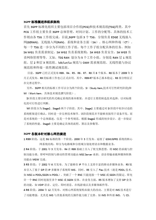
3GPP标准概述和组织架构首先3GPP标准化组织主要包括项目合作组(PCG)和技术规范组(TSG)两类。
其中PCG工作组主要负责3GPP总体管理、时间计划、工作的分配等,具体的技术工作则由各TSG工作组完成。
目前,3GPP包括3个TSG,分别负责EDGE无线接入网(GERAN)、无线接入网(RAN)、系统和业务方面(SA)、核心网和终端(CT)。
每一个TSG进一步分为不同的工作子组,每个工作子组分配具体的任务。
例如SA WG1负责需求制定,SA WG2负责系统架构,SA WG3负责安全,SA WG5负责网络管理等等。
又如,TSG RAN 划分为5个工作小组,分别是RAN层1规范组、层2和层3规范组、lub/Lur/Lu规范与OAM需求规范组。
无线性能与协议规范组和终端一致性测试规范组。
目前,3GPP已经正式发布R99、R4、R5、R6、R7、R8共6个版本。
R8版本于2009年3月正式发布,R9的标准工作也已正式启用。
其中,R99-R7版本已基本稳定,R8部分特征正在完善过程中。
另外,3GPP相关的标准工作可以分为两个阶段:SI(Study Item,技术可行性研究阶段)和WI(Work Item,具体技术规范撰写阶段)。
SI阶段主要以研究的形式确定系统的基本框架,并进行主要的候选技术选择,以对标准化的可行性进行判断。
WI阶段分为Stage2、Stage3两个子阶段。
其中,Stage2主要通过对SI阶段中初步讨论的系统框架进行确认,同时进一步完善技术细节。
该阶段规范并不能够直接用于设备开发,而是对系统的一个总体描述,仅是一个参考规范,根据Stage2形成的初步设计,进一步验证了系统的性能。
Stage3主要是确定具体的流程、算法及参数等。
3GPP各版本针对核心网的演进1 R99阶段:这是3G标准的第一个阶段,2000年3月发布。
延续了GSM/GPRS系统的核心网系统结构,即分为电路域和分组域分别处理语音和数据业务。
我国LTE-V2X标准化及测试验证进展
收稿日期:2019-09-25我国LTE-V2X标准化及测试验证进展Progress on LTE-V2X Standardization and Testing in China为了研究如何加快我国LTE-V2X 研发和产业化进程,促进实现跨行业、跨厂家的互联互通,系统性梳理了我国在LTE-V2X 领域的标准化工作,包括汽车、信息通信、交通运输和交通管理等各个行业的关注重点和进展情况。
在此基础上,介绍了相关标准的测试验证和应用示范情况,有效验证了我国LTE-V2X 标准的有效性和产业化成熟度。
LTE-V2X ;标准化;C-V2XIn order to accelerate the research and development progress of LTE-V2X in China , also to promote the cross industry interoperability ,in this paper we present the LTE-V2X standardization in summary, including automotive, communication, intelligent transportation and traffi c management industries. On this basis, we introduce the LTE-V2X related testing and demonstration in general, which verified the efficiency of LTE-V2X standards and the industrialization progress.LTE-V2X; standardization; C-V2X(中国信息通信研究院,北京 100191)(China academy of information and communications Technology, Beijing 100191, China)【摘 要】【关键词】葛雨明GE Yuming[Abstract][Key words]doi:10.3969/j.issn.1006-1010.2019.11.006 中图分类号:TN929.5 文献标志码:A 文章编号:1006-1010(2019)11-0036-04引用格式:葛雨明. 我国LTE-V2X标准化及测试验证进展[J]. 移动通信, 2019,43(11): 36-39.0 引言LTE-V2X 技术是我国主导推动的基于3GPP R14版本全球统一标准的车用无线通信技术(V2X, Vehicle to Everything )[1-2],通过将“人、车、路、云”等交通参与要素有机地联系在一起,不仅可以支撑车辆获得比单车感知更多的信息,促进自动驾驶技术创新和应用,还有利于构建一个智慧的交通体系,促进汽车和交通服务的新模式、新业态发展,对提高交通效扫描二维码与作者交流OSID :率、节省资源、减少污染、降低事故发生率、改善交通管理具有重要意义[3]。
URLLC应用场景及其关键技术(...

URLLC应用场景及其关键技术(...URLLC应用场景及其关键技术一、概述工信部5G技术研发试验第二阶段“技术方案验证”中,低时延高可靠(URLLC)是一个重要的测试场景。
2017年中国国际信息通信展的第二届5G创新发展高峰论坛上,IMT-2020(5G)推进组发布了第二阶段测试结果。
那么,URLLC测试结果如何解读和连接,其应用场景和关键技术又有哪些哪?2017/9/18~20在芬兰赫尔辛基举行的IEEE通信和网络标准化工作会议上,爱立信主任级研究专家Janne Peisa博士作了“5G URLLC 通信技术”的讲座,本文借助其演讲文稿,对URLLC应用场景、指标需求以及关键技术进行分析。
/files/2017/08/Janne_Peisa_Ericsson_CSCN2017.pdf二、二阶段URLLC测试结果低时延高可靠测试要求在大量数据包的基础上(>10^7)统计空口传送时延和丢包率,以确定时延和可靠性指标。
根据ITU要求,空口时延应小于1ms,因此丢包率指标是在1ms时延的基础上进行统计的。
比如,用户面下行传输丢包率的计算公式是,以成功传输并满足用户面下行单向时延小于1ms的包的数量除以总的测试包数量,得到下行传输丢包率。
1ms的空口时延大致包括下行传输、上行传输、缓存、UE处理、BTS处理、传输链路时延等阶段。
测试规范中建议采用思博伦仪表进行收发包测试和统计。
设备规范中所要求的性能指标为:5个测试厂家的配置各不相同,如TTI长度多种多样,如0.125ms、0.2ms、0.25ms以及0.5ms等。
子载波间隔也有所不同,包括30/60KHz等,编码方式有Polar、LDPC以及Turbo等,且均采用了自包含帧结构。
测试结果表明,各厂家单向空口时延均小于0.64m,可靠性>99.999%,满足ITU要求。
三、 Janne Peisa博士讲座内容:5G URLLC技术1. 5G URLLC应用场景1.1 5G是应用场景驱动型技术5G包括三大应用场景,即增强移动宽带(eMBB)、海量大连接(mMTC)以及重要大连接(cMTC)。
