CMA5000 SDH User_s Guide(c)——E1测试仪
ANT(SDH测试仪)

[浏览次数:246次]SDH接入测试仪SDH接入测试仪设计特别适合于现场操作,体积小、结构坚固,能够由电池供电。
它的先进特性与自动测试功能使得技术人员能够快速而有效地执行测试。
在一个结构紧凑的测试仪内集成了SDH、 PDH、 SONET 以及 ATM 测试功能,可以大大减少资金投入与培训开销,使得业务成本减到最小。
目录∙SDH接入测试仪特点∙SDH接入测试仪参数∙SDH接入测试仪特点o体积最小、重量最轻(仅2.2kg)的测试解决方案,用于从1.544 Mbps 到2.5 Gbps接口的测试大屏幕,简单图形化界面,中文菜单- 易于掌握,减少培训时间大OK结果显示- 易于使用,减少安装时间光接口的测试,双波长(1310&1550nm),从STM-1/OC-3到STM-16/OC-48 (155M、622M、2.5G)电接口的测试,DS1、E1、E3、DS3、E4、TM-0以及STM-1/OC-3(1.5M到155M)自动配置- 侦测实际的信号结构BERT测试,G.821, G.826, G.828, G.829, ANSI, M.2100和M.2101结果分析采用Sa bit发生功能以及灵活的MUX/DEMUX(复用分解)测试设置进行深入的PDH分析在线监测与通过模式可进行流量分析和网络测试光功率测试验证物理层性能ATM分析功能,用于ATM与3G/UMTS网络(由T载波、PDH、SDH/SONET提供)的业务验证SDH/SONET信号的级联映射(T)的完整分析自动保护倒换时间(APS)测试RTD(环路时延)测试指针产生和分析SOH(段开销)与POH(通道开销)分析与处理ECL/NRZ端口能够对光网络进行无干扰式直接监测IP PING和Trace Route(路由跟踪)测试功能(IP over ATM功能支持,选件)光口测试(功耗最大)时,电池操作时间为3小时PC离线观测软件可加载、分析与打印结果,并可通过以太网接口进行PC远程控制SDH接入测试仪参数o接入技术人员的选择SDH接入测试仪可以提供在当今的接入网中所需要的所有的传输测试功能:光功率测量比特误码率测试G.821, G.826, G.828, G.829, M.2100,M.2101 分析接收信号偏移测量发送信号偏移与发生表格与图形化事件记录扩展的SDH/SONET 特性SDH接入测试仪具有SDH 与SONET 测试特性,能够覆盖高至 2.5 Gbps 的所有安装与维护任务:STM-1e/STS-3 接口STM-1/OC-3 到STM-16/OC-48 光端口1310 nm 与1550 nm 波长自动配置异常与故障发生与分析APS 测量RTD 测量SOH 与POS 分析与处理(HEX 或文本格式)路径跟踪发生与分析级联监测(TCM)自动支路扫描指针产生和分析K 字节捕获完全支持PDH采用包括E1 Sa 比特发生与显示等高级功能,由1.5 Mbps 到140 Mbps ,包括N × 64kbps , ANT - 5 能够测试所有PDH 支路以及传统的PDH 体系传输系统。
EC911氧分析仪中文说明书

7.0 安装.....................................................................................................................................8
7.1 仪器的安装......................................................................................................................................................................... 8 7.2 气路的连接......................................................................................................................................................................... 9 7.3 供电电路安装................................................................................................................................................................... 10
中国华电集团公司火力发电工程设计导则(B版)

中国华电集团公司火力发电工程设计导则(B版)中国华电集团公司2015年6月北京中国华电集团公司火力发电工程设计导则(B版)编制单位:华电技术经济研究院批准部门:中国华电集团公司中国华电集团公司前言《中国华电集团公司火力发电工程设计导则(A版)》(以下简称“导则(A 版)”)自2005年7月颁布后已执行十余年。
近年来随着国家火电项目产业政策的变化,新的《大中型火力发电厂设计规范》(GB50660-2011)、《火电厂大气污染物排放标准》(GB13223-2011)、《煤电节能减排升级与改造行动计划(2014—2020年)》等陆续印发,电力行业新技术、新设备不断发展,集团公司的火电工程建设目标也转变为建设“安全优质、高效环保、指标先进、竞争力强”的电厂,2015年又提出了更高的“三同领先”要求,为积极响应这些变化和要求,更好的指导火电项目开展初步设计及优化工作,在总结导则(A版)实施经验教训的基础上,集团公司于2013年3月启动对导则(A版)进行修编。
2013年10月完成导则修编的征求意见稿,2013年11月集团公司有关部门及二级机构进行了内部评审,2014年2月委托电力规划设计总院进行了全面的评审,至2015年5月全面完成了《中国华电集团公司火力发电工程设计导则(B版)》(以下简称“导则(B版)”)的修编工作。
本导则共分21章。
主要技术内容有:总则,厂址选择,总体规划,机组选型,主厂房区域布置,运煤系统,锅炉设备及系统,除灰渣系统,烟气脱硫系统,烟气脱硝系统,汽轮机设备及系统,水处理系统,信息系统,仪表与控制,电气设备及系统,水工设施及系统,辅助及附属设施,建筑与结构,采暖通风,环境保护,劳动安全职业卫生。
本导则由中国华电集团公司火电产业部归口管理,由华电技术经济研究院负责具体内容解释。
执行过程中如有意见或建议,请及时反馈华电技术经济研究院,以便今后修订时参考。
目录1 总则............................................................................................................................... - 1 -2 厂址选择................................................................................................................................. -3 -2.1 基本规定........................................................................................................................ - 3 -2.2 厂址自然条件................................................................................................................ - 4 -2.3 建厂资源条件................................................................................................................ - 7 -2.4 国家及地方环境保护政策.......................................................................................... - 10 -2.5 发电厂选址其他要求.................................................................................................. - 11 -3 总体规划............................................................................................................................... - 12 -3.1 基本规定...................................................................................................................... - 12 -3.2 厂区外部规划.............................................................................................................. - 13 -3.3 厂区规划及总平面布置.............................................................................................. - 13 -4 机组选型............................................................................................................................. - 16 -4.1 机组参数...................................................................................................................... - 16 -4.2 机组选型...................................................................................................................... - 18 -4.3 主机容量匹配.............................................................................................................. - 20 -5 主厂房区域布置................................................................................................................... - 21 -5.1 基本规定...................................................................................................................... - 21 -5.2 汽机房及除氧间布置.................................................................................................. - 21 -5.3 煤仓间布置.................................................................................................................. - 22 -5.4 锅炉布置...................................................................................................................... - 23 -5.5 集中控制室和电子设备间布置.................................................................................. - 23 -5.6 烟气脱硫设施布置...................................................................................................... - 24 -5.7 烟气脱硝设施布置...................................................................................................... - 24 -5.8 维护检修...................................................................................................................... - 25 -6 运煤系统............................................................................................................................... - 26 -6.1 基本规定...................................................................................................................... - 26 -6.2 卸煤设施...................................................................................................................... - 26 -6.3 贮煤场及其设备.......................................................................................................... - 28 -6.4 带式输送机系统.......................................................................................................... - 30 -6.5 筛碎设备...................................................................................................................... - 31 -6.6 混煤设施...................................................................................................................... - 32 -6.7 循环流化床锅炉运煤系统.......................................................................................... - 32 -6.8 运煤系统辅助设施...................................................................................................... - 32 -6.9 入厂煤入炉煤计量及采制化设施.............................................................................. - 33 -7 锅炉设备及系统..................................................................................................................... - 38 -7.1 锅炉设备...................................................................................................................... - 38 -7.2 煤粉制备...................................................................................................................... - 39 -7.3 烟风系统...................................................................................................................... - 42 -7.4 点火、助燃油系统及锅炉辅助系统.......................................................................... - 43 -7.5 启动锅炉...................................................................................................................... - 44 -7.6 循环流化床锅炉系统.................................................................................................. - 44 -7.7 进口配套产品和阀门.................................................................................................. - 44 -8 除灰渣系统............................................................................................................................. - 46 -8.1 基本规定...................................................................................................................... - 46 -8.2 除渣系统...................................................................................................................... - 46 -8.3 除灰系统...................................................................................................................... - 48 -8.4 干灰分选系统.............................................................................................................. - 49 -8.5 石子煤处理系统.......................................................................................................... - 50 -8.6 循环流化床锅炉除灰渣系统...................................................................................... - 50 -8.7 厂外干灰渣输送系统.................................................................................................. - 50 -8.8 除灰渣系统辅助检修设施和防护设施...................................................................... - 51 -8.9 除尘设备...................................................................................................................... - 51 -9 烟气脱硫系统....................................................................................................................... - 54 -9.1 基本规定...................................................................................................................... - 54 -9.2 吸收剂制备系统.......................................................................................................... - 55 -9.3 二氧化硫吸收系统...................................................................................................... - 57 -9.4烟气系统....................................................................................................................... - 58 -9.5 脱硫副产品处置系统.................................................................................................. - 59 -9.6 脱硫系统设备进口范围.............................................................................................. - 60 -10 烟气脱硝系统....................................................................................................................... - 61 -10.1 基本规定.................................................................................................................... - 61 -10.2 选择性催化还原烟气脱硝(SCR)工艺 ................................................................ - 62 -10.3 选择性非催化还原烟气脱硝(SNCR)工艺.......................................................... - 66 -11 汽轮机设备及系统............................................................................................................... - 67 -11.1 汽轮机设备................................................................................................................ - 67 -11.2 主蒸汽、再热及旁路系统........................................................................................ - 67 -11.3 给水及除氧系统........................................................................................................ - 68 -11.4 凝结水系统................................................................................................................ - 71 -11.5 辅机冷却水系统........................................................................................................ - 71 -11.6 供热式机组的辅助系统和设备 ................................................................................ - 72 -11.7 进口配套产品和阀门................................................................................................ - 72 -12 水处理系统........................................................................................................................... - 74 -12.1 基本规定.................................................................................................................... - 74 -12.2 锅炉补给水处理........................................................................................................ - 75 -12.3 汽轮机组凝结水精处理............................................................................................ - 81 -12.4 热力系统的化学加药................................................................................................ - 82 -12.5 热力系统的水汽取样及监测.................................................................................... - 83 -12.6 冷却水处理................................................................................................................ - 83 -12.7 热网补给水及生产回水处理.................................................................................... - 84 -12.8 制氢和供氢................................................................................................................ - 85 -12.9 废水处理及回用........................................................................................................ - 86 -13 信息系统............................................................................................................................... - 88 -13.1 基本规定.................................................................................................................... - 88 -13.2 信息系统总体规划.................................................................................................... - 88 -13.3 厂级监控信息系统.................................................................................................... - 89 -13.4 管理信息系统............................................................................................................ - 89 -13.5 视频监视系统............................................................................................................ - 91 -13.6 视频会议系统.......................................................................................................... - 91 -13.7 门禁管理系统............................................................................................................ - 92 -13.8 培训仿真机................................................................................................................ - 92 -13.9 信息安全.................................................................................................................... - 92 -14 仪表与控制........................................................................................................................... - 94 -14.1 基本规定.................................................................................................................... - 94 -14.2 自动化水平................................................................................................................ - 94 -14.3 控制方式.................................................................................................................... - 95 -14.4 集中控制室和电子设备间...................................................................................... - 95 -14.5 检测与仪表.............................................................................................................. - 96 -14.6 报警............................................................................................................................ - 97 -14.7 机组保护.................................................................................................................... - 97 -14.8 开关量控制................................................................................................................ - 98 -14.9 模拟量控制................................................................................................................ - 99 -14.10 机组控制系统.......................................................................................................... - 99 -14.11 辅助车间控制系统................................................................................................ - 102 -14.12 仪表与控制系统选型............................................................................................ - 103 -14.13 控制电源和气源.................................................................................................... - 103 -14.14 仪表与控制系统进口范围.................................................................................... - 104 -15 电气设备及系统................................................................................................................. - 105 -15.1 发电机与主变压器.................................................................................................. - 105 -15.2 电气主接线.............................................................................................................. - 106 -15.3 主要电气设备选择.................................................................................................. - 108 -15.4 厂用电系统.............................................................................................................. - 110 -15.5 电气设备布置.......................................................................................................... - 113 -15.6 直流系统及交流不间断电源.................................................................................. - 115 -15.7 励磁系统................................................................................................................ - 116 -15.8 电气监控及继电保护系统...................................................................................... - 116 -15.9 照明系统................................................................................................................ - 117 -16 水工设施及系统................................................................................................................. - 119 -16.1 水务管理.................................................................................................................. - 119 -16.2 供水系统.................................................................................................................. - 121 -16.3 取排水建筑物.......................................................................................................... - 122 -16.4 空冷系统.................................................................................................................. - 124 -16.5 湿式冷却塔.............................................................................................................. - 126 -16.6 给水和废水排放...................................................................................................... - 126 -16.7 贮灰场...................................................................................................................... - 127 -16.8水工专业试验........................................................................................................... - 128 -17 辅助及附属设施................................................................................................................. - 130 -17.1 基本规定.................................................................................................................. - 130 -17.2 辅助生产系统.......................................................................................................... - 130 -17.3 辅助建筑.................................................................................................................. - 131 -17.4 附属建筑.................................................................................................................. - 132 -17.5 辅助及附属建筑物建筑装修标准.......................................................................... - 134 -18 建筑与结构....................................................................................................................... - 136 -18.1 基本规定.................................................................................................................. - 136 -18.2 建筑设计.................................................................................................................. - 137 -18.3 主厂房结构.............................................................................................................. - 139 -18.4 地基与基础.............................................................................................................. - 140 -18.5 直接空冷构筑物...................................................................................................... - 141 -18.6 烟囱及烟道结构...................................................................................................... - 142 -18.7 运煤建(构)筑物.................................................................................................. - 142 -18.8 主厂房及集中控制室建筑装修标准...................................................................... - 143 -19 采暖、通风和空气调节................................................................................................... - 146 -19.1 基本规定.................................................................................................................. - 146 -19.2 主厂房采暖、通风.................................................................................................. - 146 -19.3 主厂房空气调节系统.............................................................................................. - 147 -19.4 制冷站...................................................................................................................... - 148 -19.5 采暖加热站.............................................................................................................. - 149 -19.6 厂区管道.................................................................................................................. - 149 -19.7 运煤系统采暖通风除尘.......................................................................................... - 149 -19.8 厂外取水和灰场建(构)筑物采暖通风空调 ...................................................... - 150 -19.9 脱硫、脱硝建筑通风空调除尘.............................................................................. - 150 -20 环境保护和水土保持......................................................................................................... - 152 -20.1 基本规定.................................................................................................................. - 152 -20.2 大气污染防治.......................................................................................................... - 152 -20.3废水利用及排放....................................................................................................... - 153 -20.4 厂区噪声污染防治.................................................................................................. - 154 -20.5 灰渣污染防治和综合利用...................................................................................... - 154 -20.6 清洁生产和总量控制.............................................................................................. - 154 -20.7 水土保持.................................................................................................................. - 155 -20.8 环境保护管理和监测.............................................................................................. - 156 -21 消防、劳动安全与职业卫生............................................................................................. - 157 -21.1 消防...................................................................................................................... - 157 -21.2 劳动安全.................................................................................................................. - 157 -21.3 职业卫生.................................................................................................................. - 158 -1 总则1.0.1 本导则适用于中国华电集团公司系统(以下简称:集团公司)及其全资、控股公司投资新建或扩建的国内燃煤火力发电工程,由集团公司投资建设、采用中国设计标准的境外燃煤火电工程可参照执行。
米勒-三合一气体检测仪使用手册说明书

Key Features• Reliable, self-cleaning VOC detector • Also includes CO, H 2S, LEL and O 2 sensors• Simple to operate • Easy to calibrate• Durable, weather-resistant rubber body• Datalogging included _and automatic • Big display with auto-backlight • Loud alarm • Bright red fl ashing LED alarms • Up to 16 hours of continuous operation• Interchangeable Lithium-ion and alkaline battery packs• Charging cradle doubles as an external battery charger• Powerful pump allows sample draws up to 100 feet (30 meters)• Low-fl ow pump alarmApplications• Re fi neries• Chemical processing• Water & wastewater facilities • Semiconductor manufacturing • Rail car and tank truck cleaning • Resin and nylon production • Underground storage • Sewer entries • Cable vaults • AgricultureThe typical con fi ned space monitormeasures oxygen, combustibles,carbon monoxide and hydrogen sul fi de. Will it keep you safe intoday ,s industrial environment? No.When doing confined space work today, you need the added broad-band protection of a PID.EntryRAEThe EntryRAE is a 4-gas monitor, plusphotoionization (PID) detector. Reliable, easy to operate, and simple to calibrate, the EntryRAE delivers added protection without added complexity.Simple, Modular, Durable PID RAE Systems is the leader in PIDs.Our plug & play, patented self-cleaning PID is the most reliable and durable PID available today.Why PID?Typical 4-gas monitors do not detect volatile organic compounds (VOCs). VOCs are combustible, and often toxic at levels far below 10% LEL. They are commonly found in:• Fuels, oils, degreasers • Industrial cleaners • Heat transfer fl uids • Solvents, paints• Plastics, resins, adhesives • Pesticides and herbicidesThese are common industrial compoundsyou fi nd in _ or bring into _a con fi ned space.LEL sensors can be poisioned by common chemicals, including:• Silicone compounds • Lead compounds • Sulfur compounds • PhosphatesJust a few parts per million of thesecompounds can degrade an LEL sensor. A PID detects VOCs!A PID is a reliable backup for your LEL sensor. Combine a PID and a 4-gas monitor and you have true protection from the unexpected.Affordable OSHA compliance plus reliable VOC protectionEntryRAECon fined Space Entry MonitorATEXMonitor only includes:• Monitor as speci fi ed • VOC sensor (PID)• CO, H 2S, LEL and O 2 sensors• Lithium-ion rechargeable calibration adapter battery • Alkaline battery adapter • 5 external fi lters • Charging cradle- 120 V wall charger, US plug, or 230 V wall charger, Euro plug • ProRAE Studio software package • Computer interface cable- RS232 to RS232 with USB adapter • Calibration adapter • User manual • Shipping caseOptional CSK II Calibration Kit• Hard transport case with pre-cut foam • Sampling wand with 15 feet (3 meters) of self-coiling Te fl on ® tubing • Tool kit• Four-gas mix – 34L (50% LEL, 20.9% O 2, 10 ppm, H 2S, 50 ppm CO)• Isobutylene – 34L (100 ppm, balance air)• Regulators and tubingTruck Mount (Accessory)• Cradle attachment for mounting on a wall • 12 V adapterAutoRAE Docking Station (Accessory)• Automated bump test and calibration system• Drop-in, pushbutton operationEntryRAESpeci fi cations *Sensor Speci fi cationsOngoing projects to enhance our products mean that these speci fi cationsare subject to change.D I S T R I BU T E D B Y :AutoRAE Docking StationTruck MountUK Office。
DEM5000S 手持式光数字分析仪 使用说明书

DEM5000S手持式光数字分析仪使用说明书南京普源电气有限公司目录1.1.关于本说明书 (4)1.2.安全须知 (4)1.3.产品清单 (5)2.概述 (6)2.1.产品简介 (6)2.2.产品图片 (7)2.3.产品技术特点 (8)2.4.产品技术参数 (8)2.5.功能说明 (10)2.5.1.串接监听 (10)2.5.2.开入量逻辑计算规则 (10)2.5.3.开关量接线方式 (11)2.5.4.航空插座接口接线说明 (12)2.5.5.同步设定 (12)2.5.6.检修设置 (12)2.5.7.整分触发 (13)3.接口及按键说明 (14)3.1.外观布局 (14)3.1.1.DEM5000S外观图示 (14)3.1.2.DEM5000S外观说明 (15)3.1.3.设备指示灯说明 (15)3.1.4.按键说明 (16)3.2.开机关机熄屏截图 (16)3.2.1.开机 (16)3.2.2.关机及重启 (16)3.2.3.暗屏锁屏 (16)3.2.4.截图 (17)4.技术参数 (18)4.1.环境条件 (18)4.2.电源 (18)4.3.屏幕规格 (18)4.4.外形尺寸及颜色 (18)5.模块功能 (19)5.1.主界面 (19)5.2.状态栏图标 (20)5.3.试验配置 (21)5.4.报文分析 (27)5.5.手动试验 (33)5.6.状态序列 (33)5.7.光数字试验 (34)5.8.光数字状态序列 (40)5.9.谐波测试 (42)5.10.滑差试验 (44)5.11.递变实验 (46)5.12.整组试验 (48)5.13.光功率计 (53)5.14.核相 (54)5.15.同步特性分析 (57)5.16.极性测试 (58)5.17.时间同步检测 (60)5.18.报文记录 (62)5.19.SCD比对 (65)5.20.文档管理 (68)5.21.系统设置 (69)6.维护事项 (71)6.1.更换电池 (71)6.2.电池维护及充电 (71)6.3.屏幕维护 (71)6.4.故障排除 (71)前言1.1.关于本说明书本说明书提供了DEM5000S手持式光数字分析仪的介绍及其使用说明,说明书中介绍了产品的使用方法及各模块的功能以及如何安全使用本测试仪,请您在使用产品前务必阅读本说明书。
天馈线测试仪
例:下图说明了馈线在20.6米处的连接器性能良好,77.2米处的连接器性能失效。
电缆损耗(Cable Loss)
故障定位-回波损耗测试
故障定位-驻波比测试
双通道显示 校准
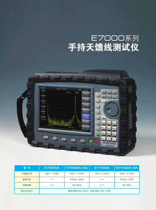
E7000系列手持天馈线测试仪和E8000系列手持频谱分析仪是德 力在15年以上标准矢量网络分析仪和标准频谱分析仪的基础上经过 创新低功耗、高集成度设计,并紧密结合国内无线通讯领域施工、调 试、维护的现场工作需要而量身定做的全新产品,更适合现场的实际 应用。
专业的权威认证是肯定,产品通过了中国工业和信息化部通信计 量中心和信息产业部电子602计量站严格的技术认定,并取得了《校 准证书》。经过多方现场工程师实际应用,得到了更简便、更适宜现 场应用的结论,并通过同类产品的相关比对测试等,充分证明该产品 性能已经达到或超过同类产品水准。
合格线自动判断
根据施工要求,设置相应合格门限值。自动判断测试结果是否合 格。
3G/4G无线通讯网络的快速发展,三网融合的快速推进,极大的 丰富了无线通讯业务,因此新一代无线网络的建设、升级及维护是近 阶段的重点工作,无线传输网络的质量保障是重中之重,也是保障多 业务可靠运营的关键。一个可靠、稳定、简洁、适宜的调试维护设备 是必不可少的。
USB电缆连接仪器,从USB口供电而不需外加直流电源。 功率计也可以通过和安装windows系统的PC连接,利用软件完成测量,实现数据记录, 得出功率值随时间变化的趋势图。(图2)
GPS卫星测试选件
测试当前确切位置(经度、纬度和高度)和通用的时间信息。测试该位置卫星数量是否 达到开站要求。(图3)
CMA5000 SDH 用户手册中文
10
连接到输入接口处的外部 PDH 信号将被插入 SDH 帧。 - 取出一个 PDH 通道: 在”Rx”窗口,选择需要删除的支路。(下面给出了一个 E3 支路的实例) :
CMA5000_XTA User Guide
CMA5000_XTA 用户指南
安立有限公司
1 1.1 1.2
1.3 1.4
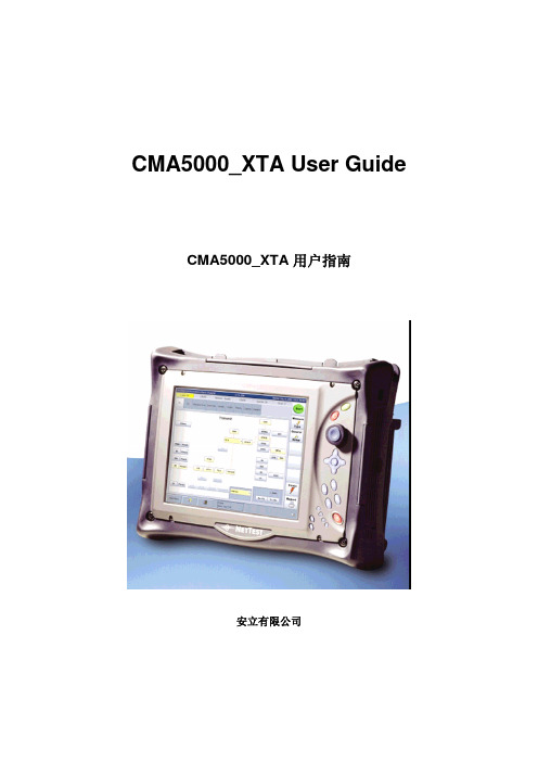
SDH 用户指南 ....................................................................................... 3 测量设定............................................................................................. 3 1.1.1 总设定 .......................................................................................... 3 1.1.2 加载测试配置................................................................................ 5 1.1.3 设定测试配置................................................................................ 6 1.1.4 保存测试配置.............................................................................. 18 进行测量........................................................................................... 19 1.2.1 启动/停止测量............................................................................. 19 1.2.2 路径分析..................................................................................... 21 1.2.3 往返时延..................................................................................... 31 1.2.4 自动保护倒换测试....................................................................... 34 1.2.5 结构扫描..................................................................................... 36 1.2.6 故障扫描..................................................................................... 37 1.2.7 性能 ............................................................................................ 39 1.2.8 保存结果..................................................................................... 43 压力功能........................................................................................... 45 1.3.1 生成告警和错误 .......................................................................... 45 1.3.2 指针和频率压力 .......................................................................... 47 报告 .................................................................................................. 49 1.4.1 创建报告..................................................................................... 50 1.4.2 打印报告..................................................................................... 50 1.4.3 保存报告..................................................................................... 51 1.4.4 载入报告..................................................................................... 51
安立推出新的NGN现场测试平台——CMA5000a

◆
测试
支持可编程的命令进行远程控 制操作或 自动化 的
测试需要的灵活性 、 携性 和 易用性 现场测 试平 台 。其 可 便 以对从 光纤到传输所 有层 面 的安装 、 护进行 深度 的高 级 维
分析 , 目前只需要 一 台仪表就 可 以进行 下一代 网络 的建 设
和维护 。
置
◆
兼容以前的 C MA5 0 0 0的模块
◆
可以根据网络技术或技术工程 师的职责来 进行配
◆
丢 失
支持电池供 电操作 , 保仪 表在测 试时 数据 不会 确
C MA5 0 a 0 0 的特征如下 : ◆ ◆ 现场使用简单 而坚 固的设计 可 以支 持 3 O多个 测试 模块 , 包括 从 OT R、 D、 D C
为 了更快更便捷 的完成 网络部署 , R&s公 司为 网络运 营商提供 了 R&S MW ,这 种 通用 移 动通 信扫 频 仪具 有 TS
Wi X的功能 , 的频率 范 围从 3 MHz到 6 MA 它 0 GHz 。它 对
的信道测量就是一个很好 的例子 。
NI 新 推 出针对 L b I W 软 件 的 高性 能 、 最 aV E
于带宽最高到 2 MHz的所有 通信技 术 。并 可 以通 过软 件 0
选件 的方式针对现在和未来 的各种标 准进 行升级 。
提供了高度的灵活性 : 仪表 可 以将 I 原始 数据 输 出, q 这样 用户可 以使用 MATL AB软件对 数据进 分析 。这种 处理方
式对于测试处 在发 展 中 的标 准有 很大 的 优势 , G P L E 3P T
月蚀导向仪使用说明书(中文)

所有经由 DCI 制造和销售的产品都受有限售后保证书中的条件约束。在您的DigiTrak® Eclipse® 定位系统用 户 手 册 中 附 有 一 份 有 限 售 后 保 证 书 ; 您 也 可 以 向 当 地 的 DCI 代 理 商 索 取 , 或 者 可 以 在 DCI 的 网 站 上取得。
Digital Control Australia 2/9 Frinton Street Southport, Queensland 4215 Australia Tel +61(0) 7 5531 4283 Fax +61(0) 7 5531 2617 DCI.Australia@
Digital Control China USA Excalibre, Shanghai Office 2803 Bldg C, 70 Cao Bao Rd Shanghai P.R.C. 200233 Tel +86 21 6432 5186 Fax +86 21 6432 5187 DCI.China@
¾ 将 DigiTrak® Eclipse® 接收器重新定向或定位。 ¾ 加大 DigiTrak® Eclipse® 接收器和出现问题的设备之间的距离。 ¾ 将设备和不同回路的电源插座连接。 ¾ 向代理商寻求协助。
未经本公司明确同意和进行的 DCI 设备变更或改造,将使本公司对用户的有限售后保证和联邦通讯委员会 (FCC)对设备操作的授权无效。
商标
DCI 标志、 CableLink®、 DataLog®、 DigiTrak®、Eclipse®、iGPS®、Intuitive®、look-ahead®、SST®、Super Sonde®、target-in-the-box®、以及Target Steering® 均为数字控制公司之美国注册商标; DucTrak™、 FasTrak™、SuperCell™ 和 TensiTrak™ 为数字控制公司(Digital Control Incorporated) 之注册商标。
导向仪使用说明
显示下一条 | 关闭萧瑟我还年轻,我渴望上路!导航•首页•日志•相册•音乐•收藏•博友•关于我日志liuwenzh 加博友关注他最新日志该作者的其他文章博主推荐相关日志随机阅读首页推荐全站仪的使用水平定向钻钻进轨迹和控制ECLIPSE月蚀导向仪的使用说明工作仪器2010-04-17 20:48:15 阅读554 评论2 字号:大中小订阅目录安全预防措施和警告事项........................................................................................................................ .. (5)概述........................................................................................................................ .. (7)接收器........................................................................................................................ .. (9)打开接收器........................................................................................................................ . (9)拨动式和触发式开关........................................................................................................................ .. (9)调整屏幕明暗对比........................................................................................................................ (10)主菜单........................................................................................................................ (10)Locate (定位)菜单........................................................................................................................进入定位模式........................................................................................................................ .. (12)离开定位模式并且回到主菜单 (12)(从定位屏幕)显示深度 (12)Set US(超声波测量值设定)菜单 (13)改变超声波测量值........................................................................................................................ .. (13)查看超声波测量设定值 (1)3Low Fre/High Fre(低频/高频设定)菜单 (14)改变频率设定值........................................................................................................................ .. (14)改变频率设定值........................................................................................................................ .. (14)Configure(设置)菜单........................................................................................................................ ..14变更遥感信号频道........................................................................................................................ .. (15)单点校准........................................................................................................................ (16)双点校准/ 地下校准........................................................................................................................ ..20变更斜度模式........................................................................................................................ .. (22)变更深度测量模式........................................................................................................................ .. (22)冷暗/正常屏幕........................................................................................................................远程显示器........................................................................................................................ . (23)键盘........................................................................................................................ . (23)打开远程显示器........................................................................................................................ . (23)扬声器和警告声........................................................................................................................ . (24)调整屏幕明暗对比........................................................................................................................ (24)主菜单........................................................................................................................ (25)Configure (设置)菜单........................................................................................................................ .26远程显示器屏幕........................................................................................................................ . (27)传感器........................................................................................................................ (31)Eclipse 传感器的类型........................................................................................................................ .. (31)倾角和面向角信息........................................................................................................................ (31)电池........................................................................................................................ . (32)温度更新信息和过热指标.......................................................................................................................32 DigiTrak® Eclipse® 用户手册3数字控制公司®目录(续)传感器(续)传感器启动及频率模式........................................................................................................................ (33)启动标准型Eclipse传感器 (33)启动双频Eclipse传感器 (33)睡眠模式(自动关闭)....................................................................................................................... . (34)传感器舱体要求........................................................................................................................ . (34)传感器的一般维护方法........................................................................................................................ (35)电池充电器........................................................................................................................ . (37)定位........................................................................................................................ (39)定位点(FLP 和RLP) 和定位线(LL) (40)定位程序........................................................................................................................ (41)目标指引(Target Steering® )功能 (45)决定可行的目标深度........................................................................................................................ . (45)输入目标深度........................................................................................................................ . (46)将接收器放置在目标位置.......................................................................................................................47指引到达目标........................................................................................................................ . (47)有线系统........................................................................................................................ .. (49)有线系统组件........................................................................................................................ . (50)操作有线系统所需要的非DCI 配件 (52)将电源供应器连接到电源和有线传感器上 (53)有线传感器接地........................................................................................................................ . (53)打开/关闭有线传感器........................................................................................................................ (54)校准有线传感器........................................................................................................................ . (54)使用有线系统定位........................................................................................................................ (54)检视传感器深度或预测深度 (54)检视有线系统电源状况........................................................................................................................ (55)使用有线系统执行目标指引功能 (55)故障检修........................................................................................................................ .. (57)附录........................................................................................................................ (59)钻杆每钻进10英尺所增加的深度英寸值 (60)钻杆每钻进15英尺所增加的深度英寸值 (61)斜度百分数换算为度数(0.1%倾角传感器或敏感倾角传感器) (62)度数换算为斜度百分数(0.1%倾角传感器) (63)根据前定位点和后定位点之间的距离计算深度 (64)安全预防措施和警告事项重要事项:所有操作人员必须阅读和了解以下的安全预防措施和警告事项,并且必须在使用DigiTrak® Eclipse® 定位系统之前复习本用户手册。
PM5000射线探测仪操作说明书及维护保养手册

PM5000射线探测仪操作和维护手册Phone: +86.516.80138888Fax: +86.516.80138800射线探测仪,型号PM5000目录1. 介绍1.1. 总述PM5000射线监测仪是用来探测运送于控制区域的放射性和核类原料(包括特殊的核原料)的一种固定系统。
这种监测仪主要用于车辆的控制。
监测仪可在室内安装,也可在室外安装。
可能用于运输车辆的交叉边界位置;也可用于NPPs、核能企业、武器制造和贮藏厂、核浪费处理和贮藏区域的检查点,还可用于钢铁厂、银行、邮局等的入口处。
监测仪的操作环境:温度范围(℃):-30~+50;相对湿度(≤35℃时):高达95%;大气压力(kP):84~106.71.2. 装箱单监测仪的装箱单见下表1。
1.3. 规格1.3.1. PM5000监测仪能探测到γ射线并以计数率cps(周/秒)显示在液晶显示器上。
1.3.2. 一个γ探测器的灵敏性:对于241Am,不少于150cps/μp/h;对于137Cs,不少于125 cps/μp/h。
注:带有241Am,137Cs点源γ探测器的监测仪的灵敏度,在距离γ探测器50±1cm的范围内,241Am时,不少于0.35cps/kBq;137Cs时,不少于5.0 cps/ kBq。
1.3.3. 在γ射线探测期间,PM5000监测仪允许通过改变低识别水平(能量范围20keV~825keV)和高识别水平(能量范围20keV~1660keV)来设定能量系统。
1.3.4. PM5000监测仪能探测到中子射线并以计数率cps(周/秒)显示在液晶显示器上。
1.3.5. 一个NDA4-1的灵敏度,对于 Pu-α-Be源,不少于500 counts cm2/n。
1.3.6. 监测仪可发出可听见和可视的(红光)警报。
可听见的警报水平为:在距离警报点1米时不低于80分贝。
1.3.7. 根据装箱单,监测仪能探测到的放射性和核原料的最小数量见表2所示。
费加罗技研株式会社 EC01 气体传感器评价试验箱 操作使用说明书
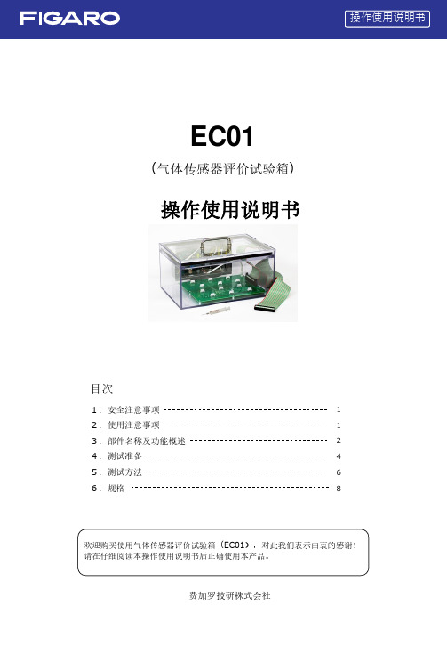
1.安全注意事项2.使用注意事项3.部件名称及功能概述4.测试准备5.测试方法6.规格目次欢迎购买使用气体传感器评价试验箱(EC01),对此我们表示由衷的感谢!请在仔细阅读本操作使用说明书后正确使用本产品。
112468费加罗技研株式会社EC01(气体传感器评价试验箱)操作使用说明书(1)(2)(3)(4)1. 安全注意事项请务必遵守2. 使用注意事项本产品是一种简易型的试验箱。
使用时请仔细盖紧盖板不能留有缝隙。
如果要进行很精确的气体测试时,请选用比本产品气密性更高的试验箱。
测试时如果将类似于气体报警器这样体积较大的设备放入试验箱的话,可能因为试验箱的有效容积减少而导致气体浓度制备出现误差。
由于氨气、VOC 、有机溶剂蒸汽等吸附性很强的气体很容易吸附在试验箱的内壁之上,因此本产品不适用于这些气体的测试用途。
吸附于箱内壁的气体液化后,有可能导致试验箱内的气体浓度下降。
有必要对吸附性很强的气体进行测试时,请选用箱内壁采用了气体不容易附着材质的试验箱,或对箱内壁进行过涂层处理的试验箱。
如果已经向本试验箱内注入了吸附性很强的气体,为了在使用后去除附着的气体,请用酒精擦拭试验箱内部,然后对内部用洁净空气进行长时间换气等的妥善处置。
如果在高温、低温或极度的低湿度与高湿度的室内环境进行测试的话,气体传感器的测定值可能会受到影响。
请在测试前对各型号传感器规格进行确认。
本试验箱没有防爆设计。
请勿在对气体爆炸下限为(LEL) 50%以上浓度的可燃性气体进行测试时使用。
本试验箱无法保证绝对完全的密闭状态。
请勿在对可能危及人身安全的高浓度毒性气体进行测试时使用。
在用于对可燃性气体进行测试时请务必注意防火措施,同时试验箱向外排气时请在可以充分换气的场所进行。
而且,为确保安全,请考虑采取设置气体报警器等措施。
尤其是在用于对毒性气体进行测试的用途时,请务必在能够保证充分换气的场所进行。
另外出于安全考虑,将试验箱中的气体排出时请注意避免人员吸入的同时,请在室外或排风罩内进行操作。
CMA5000a多层网络测试平台产品简介说明书

1981Product BrochureCMA5000a Multi-layer Network Test Platform/12 Page CMA5000aMulti-Layer Network Test PlatformAll-in-one Platform for SONET/SDH, OTN, Gigabit Ethernet, DWDM, OTDR, ORL, PMD, CDImproved customer service, easy maintenance and lower costs are key issues for operators of high-speed data services.The CMA5000a Multi-Layer Network Test Platform has a full range of versatile modules and easy to use touch panel, supporting fast network rollout and maintenance at lower total cost.• Multi-measurement FunctionsThe CMA5000a measurement modules support SONET/SDH, OTN, 10 Gigabit Ethernet, Gigabit Ethernet, DWDM, OTDR, ORL, PMD, and CD measurements.For field-testing, one unit supports all required physical layer, data link layer, network layer, and transport layer measurement items.• Lower Total Cost of OwnershipOne CMA5000a supports all measurements required for rolling out an optical network and maintenance follow-up. Multiple measurementmodules can be set and operated simultaneously in one mainframe, eliminating the need for other single-function specialist measuring instruments and cutting total cost of ownership.The easy to use touch panel and GUI shorten operator training too.• Fast Service Roll-outThe consistent GUI between measurement modules simplifies work, allowing the operator to focus on evaluating each network layer efficiently and contributing to the fastest service rollout and maintenance.A touch of a button can generate PDF-formatted report of measurement conditions and results.Engineer can operate CMA5000a over Ethernet to support measurements at local site.2/12 PageCMA5000a Multi-layer Network Test PlatformDeployment of ServiceNetwork CommissioningDWDM Network Equipment InstallationPhysical Medium CharacterizationSmall Bay Adapter (SBA)PlatformThe open architecture and familiar PC GUI ensurethat the CMA5000a can be updated to meet theevolving measurement needs of communicationsnetworks.Two platforms of different sizes coupled with a fullrange of measurement modules assure support forevery test requirement. High-performancemeasurement of every application cuts the time andcost of network installation and maintenance.The CMA5000a features two types of bay adapter tohold a wide variety of application test modules,providing unsurpassed flexibility and scalability toreduce cost.Medium Bay Adapter (MBA)CMA5000a Multi-layer Network Test Platform /12 PageCMA5000a SpecificationsWindows® is a registered trademark of Microsoft Corporation in the USA and other countries.Celeron® is a registered trademarks of Intel Corporation or its subsidiaries in the USA and other countries4/12 Page CMA5000a Multi-layer Network Test PlatformAnalysis of Captured DataMeasurement Results of Two Ports with User Adjustable ThresholdsTransmission Equipment and Network Performance MeasurementsThe CMA5000a support various transmission equipment and network performance measurements.Its easy operation coupled with event log and reporting functions make it perfect for field measurements.GigE II Module: Ethernet (10/100/1000BASE-T, 1000BASE-X)UTA Module: S DH/SONET (156M to 9953 Mbit/s)OTN (2.6G, 10.7G, 11.049G, 11.095G)Ethernet (10GBASE-X, LAN-PHY/WAN-PHY)XTA Module: SDH/SONET/PDH/DSn (1.5M to 9953 Mbit/s) Jitter and Wander (1.5M to 2488 Mbit/s) NGN (1.5M to 2488 Mbit/s)With a full line of versatile modules, the all-in-one CMA5000a simplifies operation and cuts measurement costs.Gigabit EthernetThe GigE II Module is a single unit supporting up to Gigabit Ethernet measurement with two RJ-45 ports for 10/100/1000BASE-T and two SFP ports for 1000BASE-X.Optical 100M interface (100BASE-FX MMF) is also supported.Users can identify both network faults and the root cause using flexible Tx stream generation, received frame analysis, and ping functions (Tx/Rx, Trace Route).Moreover, the GigE II supports qualitymeasurements of various services using sequence error, latency, and IP packet jitter measurement functions. The GigE II module has built-in support for RFC2544 applications and supports easymeasurement of throughput, latency, and frame loss as well as back-to-back tests.The unique BERT function supports line quality measurement using various data patterns.10 Gigabit EthernetThe dual-size UTA Module supports various 10G interfaces for LAN-PHY/WAN-PHY 10 Gigabit Ethernet measurements. Utilizing swappable XFP modules as optical interfaces make wavelength switching easy.Users can identify both network faults and the root cause using flexible Tx stream generation, received frame analysis, and ping functions (Tx/Rx) as well as a capture function with filtering/triggering.In addition, the UTA module supports variousservice quality measurements using sequence error, latency and IP packet jitter measurement functions. The RFC2544 application supports measurement of throughput, latency, and frame loss as well as easy back-to-back testing.CMA5000a Multi-layer Network Test Platform 5/12 PageSDH/SONETThe dual-size UTA and XTA measurement modulessupport SDH/SONET interfaces from 156M to 9953M. In addition to offering various functions, such as alarm/error measurement, APSmeasurement with 125 μs resolution, and return delay measurement with 100 μs resolution, field troubleshooting and fault detection are made faster and easier by search and mapping auto-analysis.Additionally, installing the optional EoS (Ethernet over SDH/SONET) function supports next-generation SDH/SONET measurements, such as virtual concatenation, LCAS, and differential delay.The XTA unit supports ITU-T O.172-compliant PDH/DSn interfaces and jitter/wander measurements from 1.5M to 2488 Mbit/s.OTNThe UTA Module supports OTN measurements as an option. It supports OTN 2.6G, 10.7G and 11.1G interfaces. Forward Error Correction (FEC) is a key index of OTN performance that the UTA Module can quantify with high reproducibility using its ITU-T O.182-compliant error generation function.The CMA Ethernet reflector has10/100/1000BASE-T and 1000BASE-X ports. It complements CMA5000a IP/Ethernetmeasurements by the function of swapping the source address and the destination address of the Ethernet frame.Mapping Selection WindowOTN Error and Alarm Display Showing Each Network LayerExternal View of CMA Ethernet Reflector6/12 Page CMA5000a Multi-layer Network Test PlatformCMA Ethernet ReflectorCMA5000a Multi-layer Network Test Platform 7/12 PageFull fiber characterization with the press of a button.Video Inspection Probe displays and captures fiber end faceOTDRThe CMA5000a Optical Time Domain Reflectometer (OTDR) application represents a world-classmeasurement solution with the latest in high performance hardware and dedicated, easy to use software.• High Performance HardwareTo satisfy the most demanding testing requirements, the CMA5000a series OTDR modules, feature a multitude of available wavelengths including 850, 1300, 1310, 1383, 1490, 1550 and 1625 nm.For ultra-long haul systems, the CMA5000a OTDR modules feature up to 50 dB of dynamic range (enough to see approximately 250 km of fiber).• Dedicated, Ease to Use SoftwareTo simplify testing, the CMA5000a featuresdedicated testing modes to automate and simplify the task at hand. FAULT LOCATE mode is designed for the novice just starting out or someone who only uses an OTDR occasionally. Simply connect the fiber and press test, the unit will verify the fiber is connected correctly, select testing parameters, execute the test and provide a text responseindicating fault/break location and end to end loss. For those who have more experience or would like to perform more advanced testing, STANDARD OTDR mode allows the user to select allparameters, compare up to eight traces and even generate splice loss reports. Cable commissioning is also automated through the use ofCONSTRUCTION OTDR mode where a wizard allows the user to select the required testing wavelengths, number of fibers and file naming scheme. The wizard then becomes the project manager guiding the user through the testing and ensuring consistency with testing parameters, eliminating user induced errors.The Video Inspection Probe (VIP) gives operators a safe, easy way to analyze and document connector conditions. Since most optical network failures are attributed to poor connector quality, the VIP reduces the installation time and ensures the network is able to reach its full potential.Connector images are captured digitally anddisplayed on the test set screen. The images can then be viewed or saved as a variety of common graphics files for later review or documentation of connector quality. Various adapters are available to allow direct viewing of patch cord end faces, as well as, for viewing of end faces already installed in patch panels.Optical Fiber Connector InspectionPhysical Layer CharacterizationAs a leader in optical fiber and network characterization, the CMA 5000a offers all of the test applications required for comprehensive physical layer characterization, including OTDR, Polarization Mode Dispersion, Chromatic Dispersion, Loss Test Set and Optical Return Loss. Supplemental tools such as a Visual Fault Locator and Video Inspection Probe are also available for a complete testing solution.8/12 Page CMA5000a Multi-layer Network Test PlatformThe OSA applications lower CWDM and DWDM installation and maintenance costs by providing industry leading spectral analysis of system critical parameters. Operating from 1250 to 1650 nm, these OSA modules for the CMA5000a are the tools for testing large wavelength range CWDM system.The OSA provides laboratory grade specifications in a rugged field module and is ideal for critical measurements on DWDM systems.With the tightest wavelength spacing and best ORR & OSNR available in a field package, it quickly and accurately identifies problems with source drift, output stability and optical amplifier operation. In addition, it features a unique flat-topped narrowband filter that can be used to drop a single channel (at speeds up to 40 Gbit/s) from the DWDM network for detailed transport testing.DWDM Network EquipmentBy performing complete PMD Characterization of your high data-rate networks, the CMA5000a PMD application helps optimize throughput and increase revenue. Its simple, one-button operation allows installers, carriers and system providers alike to release the full potential of their high line rate network spans.The unique pi-shifted interferometric technique provides high accuracy and high dynamic ranges with a standard light source. This high performance module achieves tests through multiple EDFAs, reduces testing time by fast measurements,exceptional ease of use and covers all wavelength bands. It is fully compliant with TIA/EIA FOTP-124 and IEC60793-1-48 standards.Complete channel analysis including wavelength (orfrequency), power, OSNR and system gain tilt for balancing your networkDetermine if your fiber link meets PMD requirementsPolarization Mode Dispersion (PMD)CMA5000a Multi-layer Network Test Platform 9/12 PageThe field portable CMA5000a OTDR/Chromatic Dispersion (CD-OTDR) measurement system is a dedicated module that combines the advanced capabilities of Anritsu’s OTDR technology with Anritsu’s experience in Chromatic Dispersion. The CMA5000a CD-OTDR measurement system gives installers and network providers a combined module that can be used as an OTDR and a chromatic dispersion measurement system, reducing testing times while increasing network performance.The CMA5000a CD-OTDR measurement system is based upon the industry accepted time-of-flightmeasurement method (FOTP-168) that can evaluate chromatic dispersion of individual fiber links. Utilizing a single fiber for the test and multiplewavelengths, results in an increase in the accuracy of the measurement, as well as, a reduction in the testing time. This translates into improved network performance and efficiency, resulting in increased revenue for the network provider.Anritsu understands how valuable your time is, so we provide intuitive, easy-to-use setup menus and single-button operation. The CMA5000a CD-OTDR measurement system has been designed to provide optimal test efficiency to facilitate quicker turn-up of services and reduce the cost of testing.The combined unit has an auto-test feature that will determine the optimum settings. In addition, intuitive setup menus guide the user through a few minor settings to minimize the testing and setup times.Chromatic DispersionModule SpecificationsSee each module data sheet for detailed configurations.Highly Accurate CD Measurement Using FOTP-168 Method10/12 Page CMA5000a Multi-layer Network Test PlatformOrdering InformationPlease specify the model/order number, name and quantity when ordering.The names listed in the chart below are Order Names. The actual name of the item may differ from the Order Name.NoteAnritsu Corporation5-1-1 Onna, Atsugi-shi, Kanagawa, 243-8555 Japan Phone: +81-46-223-1111Fax: +81-46-296-1264• U.S.A.Anritsu Company1155 East Collins Blvd., Suite 100, Richardson,TX 75081, U.S.A.Toll Free: 1-800-267-4878Phone: +1-972-644-1777Fax: +1-972-671-1877• CanadaAnritsu Electronics Ltd.700 Silver Seven Road, Suite 120, Kanata, Ontario K2V 1C3, CanadaPhone: +1-613-591-2003Fax: +1-613-591-1006• BrazilAnritsu Eletrônica Ltda.Praca Amadeu Amaral, 27 - 1 Andar01327-010-Paraiso-São Paulo-BrazilPhone: +55-11-3283-2511Fax: +55-11-3288-6940• MexicoAnritsu Company, S.A. de C.V.Av. Ejército Nacional No. 579 Piso 9, Col. Granada 11520 México, D.F., MéxicoPhone: +52-55-1101-2370Fax: +52-55-5254-3147• U.K.Anritsu EMEA Ltd.200 Capability Green, Luton, Bedfordshire, LU1 3LU, U.K. Phone: +44-1582-433200Fax: +44-1582-731303• FranceAnritsu S.A.16/18 avenue du Québec-SILIC 72091961 COURTABOEUF CEDEX, FrancePhone: +33-1-60-92-15-50Fax: +33-1-64-46-10-65• GermanyAnritsu GmbHNemetschek Haus, Konrad-Zuse-Platz 181829 München, GermanyPhone: +49-89-442308-0Fax: +49-89-442308-55• ItalyAnritsu S.p.A.Via Elio Vittorini 129, 00144 Roma, ItalyPhone: +39-6-509-9711Fax: +39-6-502-2425• SwedenAnritsu ABBorgafjordsgatan 13, 164 40 KISTA, SwedenPhone: +46-8-534-707-00Fax: +46-8-534-707-30• FinlandAnritsu ABTeknobulevardi 3-5, FI-01530 VANTAA, FinlandPhone: +358-20-741-8100Fax: +358-20-741-8111• DenmarkAnritsu A/SKirkebjerg Allé 90, DK-2605 Brøndby, DenmarkPhone: +45-72112200Fax: +45-72112210• SpainAnritsu EMEA Ltd.Oficina de Representación en EspañaEdificio VeganovaAvda de la Vega, n˚ 1 (edf 8, pl 1, of 8)28108 ALCOBENDAS - Madrid, SpainPhone: +34-914905761Fax: +34-914905762• RussiaAnritsu EMEA Ltd.Representation Office in RussiaTverskaya str. 16/2, bld. 1, 7th floor.Russia, 125009, MoscowPhone: +7-495-363-1694Fax: +7-495-935-8962• United Arab EmiratesAnritsu EMEA Ltd.Dubai Liaison OfficeP O Box 500413 - Dubai Internet CityAl Thuraya Building, Tower 1, Suit 701, 7th FloorDubai, United Arab EmiratesPhone: +971-4-3670352Fax: +971-4-3688460• SingaporeAnritsu Pte. Ltd.60 Alexandra Terrace, #02-08, The Comtech (Lobby A)Singapore 118502Phone: +65-6282-2400Fax: +65-6282-2533• IndiaAnritsu Pte. Ltd.India Branch Office3rd Floor, Shri Lakshminarayan Niwas, #2726,HAL 3rd Stage, Bangalore - 560 038, IndiaPhone: +91-80-4058-1300Fax: +91-80-4058-1301• P.R. China (Hong Kong)Anritsu Company Ltd.Units 4 & 5, 28th Floor, Greenfield Tower, Concordia Plaza,No. 1 Science Museum Road, Tsim Sha Tsui East,Kowloon, Hong KongPhone: +852-2301-4980Fax: +852-2301-3545• P.R. China (Beijing)Anritsu Company Ltd.Beijing Representative OfficeRoom 2008, Beijing Fortune Building,No. 5, Dong-San-Huan Bei Road,Chao-Yang District, Beijing 100004, P.R. ChinaPhone: +86-10-6590-9230Fax: +86-10-6590-9235• KoreaAnritsu Corporation, Ltd.8F Hyunjuk Building, 832-41, Yeoksam Dong,Kangnam-ku, Seoul, 135-080, KoreaPhone: +82-2-553-6603Fax: +82-2-553-6604• AustraliaAnritsu Pty. Ltd.Unit 21/270 Ferntree Gully Road, Notting Hill,Victoria 3168, AustraliaPhone: +61-3-9558-8177Fax: +61-3-9558-8255• TaiwanAnritsu Company Inc.7F, No. 316, Sec. 1, Neihu Rd., Taipei 114, TaiwanPhone: +886-2-8751-1816Fax: +886-2-8751-1817Specifications are subject to change without notice.080929Please Contact:The all-in-one CMA5000a Multi Layer Network Platform supports cost-effective network installation and maintenance measurements.MainframeThere are two models of CMA5000a mainframe—the SBA (Single Bay Adapter), and the MBA (Medium Bay Adapter), each offering different numbersSBA (2 bays)MBA (4 bays)Measurement ModulesProduct Number Description520-ORL-XXOPTION-55X-TFMXXHigh-accuracy location of optical fiber breaks52XX-000-OTDR-XXX Reflection measurement showing cut or bend of opticalfibers5302-21-CDOTDR-XXX Chromatic dispersion measurement5710-000-GIGE Transmission quality measurement for 10, 100 andGigabit Ethernet5700-000-GIGE Transmission quality measurement for 10, 100 andGigabit Ethernet5800-000-10GIGE Transmission quality measurement for 10 GigabitEthernet。
SDH中E1基础知识

E1线路知识点1、一条E1是2.048M的链路,用PCM编码。
2、一个E1的帧长为256个bit,分为32个时隙,一个时隙为8个bit。
3、每秒有8k个E1的帧通过接口,即8K*256=2048kbps。
4、每个时隙在E1帧中占8bit,8*8k=64k,即一条E1中含有32个64K。
E1帧结构------E1有成帧,成复帧与不成帧三种方式,在成帧的E1中第0时隙用于传输帧同步数据,其余31个时隙可以用于传输有效数据;在成复帧的E1中,除了第0时隙外,第16时隙是用于传输信令的,只有第1到15,第17到第31共30个时隙可用于传输有效数据;而在不成帧的E1中,所有32个时隙都可用于传输有效数据.一.E1基础知识E1信道的帧结构简述------在E1信道中,8bit组成一个时隙(TS),由32个时隙组成了一个帧(F),16个帧组成一个复帧(MF)。
在一个帧中,TS0主要用于传送帧定位信号(FAS)、CRC-4(循环冗余校验)和对端告警指示,TS16主要传送随路信令(CAS)、复帧定位信号和复帧对端告警指示,TS1至TS15和TS17至TS31共30个时隙传送话音或数据等信息。
我们称TS1至TS15和TS17至TS31为“净荷”,TS0和TS16为“开销”。
如果采用带外公共信道信令(CCS),TS16就失去了传送信令的用途,该时隙也可用来传送信息信号,这时帧结构的净荷为TS1至TS31,开销只有TS0了。
由PCM编码介绍E1:由PCM编码中E1的时隙特征可知,E1共分32个时隙TS0-TS31。
每个时隙为64K,其中TS0为被帧同步码,Si, Sa4, Sa5, Sa6,Sa7,A比特占用, 若系统运用了CRC校验,则Si比特位置改传CRC校验码。
TS16为信令时隙, 当使用到信令(共路信令或随路信令)时,该时隙用来传输信令, 用户不可用来传输数据。
所以2M的PCM码型有①PCM30 : PCM30用户可用时隙为30个, TS1-TS15,TS17-TS31。
USCAR中文第版
5.6.3高温暴露。。。。。。。。。。。。。。。。。。。。。。。。。。。。。。。。。。。。。。。。。。。。。。。。。。。。。。。。。。55
5.6.4流体阻力。。。。。。。。。。。。。。。。。。。。。。。。。。。。。。。。。。。。。。。。。。。。。。。。。。。。。。。。。。56
3.4.1样品,试验类型及专用试验。。。。。。。。。。。。。。。。。。。。。。。。。。。。。。。。。。。。。。。。。。。6
3.4.2实验要求/顺序说明。。。。。。。。。。。。。。。。。。。。。。。。。。。。。。。。。。。。。。。。。。。。。。。。。6
3.4.3性能和耐久性实验说明.。。。。。。。。。。。。。。。。。。。。。。。。。。。。。。。。。。。。。。。。。。。。。6
5.8.1高压喷射。。。。。。。。。。。。。。。。。。。。。。。。。。。。。。。。。。。。。。。。。。。。。。。。。。。。。。。。。。69
5.8.2剧烈振动。。。。。。。。。。。。。。。。。。。。。。。。。。。。。。。。。。。。。。。。。。。。。。。。。。。。。。。。。。72
SAE/USCAR-2第五修订版修订日期:2007-11
5.4.9模腔损坏系数。。。。。。。。。。。。。。。。。。。。。。。。。。。。。。。。。。。。。。。。。。。。。。。。。。。。。。48
5.4.10端子/型腔极化测试。。。。。。。。。。。。。。。。。。。。。。。。。。。。。。。。。。。。。。。。。。。。。。。。54
连接器电性能试验。。。。。。。。。。。。。。。。。。。。。。。。。。。。。。。。。。。。。。。。。。。。。。。。。。49
智能智能油品质量监测仪的技术要求

智能智能油品质量监测仪的技术要求智能油品质量监测仪是一种可以实现自动化检测和监测油品质量的设备。
它能够通过智能化技术和传感器来进行各种参数的检测,如油品温度、粘度、密度、水分含量、含硫量等。
在现代工业生产和交通运输中,油品的质量对设备和机械的工作性能和寿命有着重要的影响,因此,研发一种可靠、精确的智能油品质量监测仪具有重要意义。
首先,智能油品质量监测仪应具备高精度的测量能力。
油品的质量检测十分重要,对细小的参数变化都应敏感,因此监测仪的传感器应具备高灵敏度和准确度。
同时,监测仪应具备高分辨率的输出能力,以便更好地分析油品的质量状况。
其次,智能油品质量监测仪应具备多种参数检测的功能。
在实际应用中,不同的油品可能需要检测的参数种类和数量各不相同,因此监测仪应具备可变参数的设置,满足不同油品的质量检测需求。
同时,监测仪还应支持实时监测和记录功能,能够持续不断地对油品质量进行监测,并对数据进行存储和分析。
第三,智能油品质量监测仪应具备便捷操作和信息传输的特性。
智能化技术的应用使得监测仪能够通过触摸屏或者按键进行操作和设置,操作过程简单,便于使用。
此外,监测仪还应支持数据的无线传输,例如通过Wi-Fi或蓝牙等方式,将监测的数据传输到云端或其他设备进行处理和存储。
第四,智能油品质量监测仪应具备高稳定性和可靠性。
油品质量监测的结果直接关系到设备和机械的正常运行和使用寿命,因此监测仪本身应具备高稳定性和可靠性,确保测量结果的准确性和可重复性。
第五,智能油品质量监测仪应具备智能化数据处理和分析功能。
监测仪应能够对采集到的数据进行智能分析和处理,例如通过算法判断油品是否达到质量标准,并能够向操作人员提供相应的提示和建议。
此外,监测仪还应具备数据可视化的能力,将检测结果以图表或其他形式直观地展示出来,方便用户进行分析和决策。
综上所述,智能油品质量监测仪应具备高精度、多参数、便捷操作、信息传输、高稳定性和可靠性、智能化数据处理和分析等特性。
邯郸市秋季大气挥发性有机物污染特征

采用智能传感技术的下一代气体检测仪表ULTIMA X5000
第27卷 第9期2020年9月仪器仪表用户INSTRUMENTATIONVol.272020 No.90 引言一直以来,工程师们致力于使用多样化的气体检测技术确保油气生产、炼制、储运等环节中的安全等级,最大限度保护人员、设备和设施的安全,如果气体检测系统发生故障,其结果可能是灾难性的。
设计和使用安全、高性能的气体检测系统,能确保较长使用周期内可靠运行,并准确、及时地发现气体泄漏,从而最大限度地避免误报警、误停车等事件的频繁发生。
采用智能传感技术的下一代气体检测仪表ULTIMA X5000施晓东1,马云鹂2(1.中海石油(中国)有限公司 天津分公司,天津 300459;2.梅思安(中国)安全设备有限公司,江苏 苏州 215000)摘 要:简述了常规气体检测技术在石油化工天然气行业实际应用中的潜在问题,并引入智能传感技术的概念。
智能传感技术能够有效减除复杂多变工况环境中不利因素造成的安全风险,有效减少误报警,显著延长仪表标定周期,以及仪表有效寿命。
基于智能传感技术的梅思安下一代气体探测器ULTIMA X5000集成各类先进的检测技术,采用双探头设计,以及更加人性化的触摸屏和OLED 人机界面,适用于SIL2安全完整性等级的功能安全回路应用,显著减少误报警现象,提高安全防护等级。
关键词:智能检测技术;气体检测;误报警;安全失效;自动脉冲检测中图分类号:TH 文献标志码: ANew Generation Gas Detector ULTIMA X5000 Based on InnovativeTruCal Sensing TechnologyShi Xiaodong 1,Ma Yunli 2(1. Tianjin Branch of CNOOC(China) Co., Ltd., Tianjin,300459, China;2. MSA(China) Safety Equipment Co.,Ltd., Jiangsu,Suzhou,215000,China)Abstract:The potential risk of traditional gas detection in oil and gas industry is briefly described, then the innovative technolo-gy of TruCal is introduced. TruCal technology is helpful to effectively mitigate the environment disadvantages, so as to reduce false alarm and extend the calibration interval and lifetime. Based on TruCal technology, MSA next generation intelligent gas detector ULTIMA X5000 integrates diversified sensing technologies, adopting dual-sensor design and humanized HMI design such as touchscreen and OLED indication. X5000 is suitable in function safety applications where SIL2 is required, can help to enhance safety level with better availability.Key words:TruCal;gas detection;false alarm;safe failure;pulse check收稿日期:2020-05-07作者简介:施晓东(1977-),男,江苏海门人,硕士,研究方向:油气行业仪表自动化技术研究和应用。
- 1、下载文档前请自行甄别文档内容的完整性,平台不提供额外的编辑、内容补充、找答案等附加服务。
- 2、"仅部分预览"的文档,不可在线预览部分如存在完整性等问题,可反馈申请退款(可完整预览的文档不适用该条件!)。
- 3、如文档侵犯您的权益,请联系客服反馈,我们会尽快为您处理(人工客服工作时间:9:00-18:30)。
11
(a) 除 B1, B2, H1, H2 和 H3 外,所有的 SOH ( STM1)的字节都可以在这个屏幕 上进行编辑。 再生段, AU 指针部分和复用段部分由不同的颜色表示。
输入需要的二进制形式的预定值。为了回到每个字节的默认值, 使用
按钮
(没有初始化外部 DCC 通道的情况下)。
• 按“应用”或者“OK”按钮,改变 SOH 并关闭窗口。新的 SOH 将
被立即发送。
备注:也可以将其保存为传输配置的一部分,当配置被重新载入的时,可以再次使用 该值。
NetTest CMA5000_OTA User Guide
CMA5000_OTA 用户指南
网泰通讯科技(中国)有限公司 2004 年 5 月
1 1.1 1.2
1.3 1.4
SDH用户指南 ........................................................................................ 3 测量设定............................................................................................. 3 1.1.1 总设定 .......................................................................................... 3 1.1.2 加载测试配置................................................................................ 5 1.1.3 设定测试配置................................................................................ 6 1.1.4 保存测试配置.............................................................................. 18 进行测量........................................................................................... 19 1.2.1 启动/停止测量............................................................................. 19 1.2.2 路径分析..................................................................................... 21 1.2.3 往返时延..................................................................................... 31 1.2.4 自动保护倒换测试....................................................................... 34 1.2.5 结构扫描..................................................................................... 36 1.2.6 故障扫描..................................................................................... 37 1.2.7 性能 ............................................................................................ 39 1.2.8 保存结果..................................................................................... 43 压力功能........................................................................................... 45 1.3.1 生成告警和错误 .......................................................................... 45 1.3.2 指针和频率压力 .......................................................................... 47 报告 .................................................................................................. 49 1.4.1 创建报告..................................................................................... 50 1.4.2 打印报告..................................................................................... 50 1.4.3 保存报告..................................................................................... 51 1.4.4 载入报告..................................................................................... 51
式。
(e)根据选定的映射模式,使用
按钮应用 ITU 建议
• 请参考 PDH 和 SDH 测试章节并定义 VC4、VC3、和 VC12 的 SOH 和 POH。
1.1.3.2
SDH 测试
• 请务必定期使用专用材料清洁光连接器。
• 连接物理传输接口至前面板上的光输入/输出接口。
• 当有光信号传输时,指示灯亮,指示灯显示当前使用 1310nm 波段, 或是 1550nm 波段。
1.1.2 加载测试配置 描述: 可以保存许多常用测量设定,不用的时候可以取消。 配置可以保存在一个文件中,该文件可以保存于硬盘或者软盘(要求有 USB 端口选项) 或者 CD – RW 上 ( 要求在 CMA5000 上选中此选项)。
5
如何:
• 当你按
时显示载入菜单主屏幕
• 可以载入预先设定的配置。
2
1 SDH 用户指南
1.1 测量设定 本章包含配置测量参数的有关信息。
1.1.1 总设定
当具有 OTA 模块的 CMA 5000 与需要测试的设备连接后,在“Tx”和“Rx”屏幕上 可以设置信号类型、帧结构和界面等基本参数。 分别显示 Tx 和 Rx 的设置。 如果要修改配置,必须首先停止测试。 在测量过程中,能够使用“Tx”和“Rx”屏 幕。 活动按钮的颜色为黄色。 主按钮为 OK 或应用按钮, 用来激活你的设定选择。 默认按钮用于将一个预先设定好 的配置应用到选定的屏幕上。
•
•
1.1.3.1
PDH 测试
• 连接物理传输接口至前面板上的电输入/输出接口。 • 选择“Tx”模式屏幕。此时测量必须在停止模式。
• 对应输出 PDH 信号 E1 至 E4,按相应的 • 选择 PDH 接口
按钮,。
6
• 选择 PDH 有效负载
• 也可以选择 BER 测试
• 选择信号类型: 帧或 PRBS 有效负载。按 决于选定的映射模式)。
e) 事件分析配置:“事件分析配置”是对在网络中自动保护倒换期间内非常短的时间 内发生的故障进行分析的很有用的一个功能。 结果在 125us 精度的图表中显示。 可以 通过触发显示这个图表。使用“触发”标签设定触发器参数来显示图表。
f) 在修改“总设定”参数后,如果希望恢复出厂配置,请按“默认设定”标签并 按”Ok”或”应用”按钮。
• 出现主屏幕:
按钮(取
(a) 选择单帧 G704 或复帧 CRC4 7
(b)根据激活选定的映射模式选择 PRBS
(c)启动转化后的 PRBS 2xx - 1. 信息通过 “(i)”在在
上显示。
(d) 选择文字类型。 用用于 DS1 信号的户自定义 2 字节字 1 in 8、 2 in 8、3 in 24 模
( OTA 模块配置为通过模式) 怎样配置 OTA 模块: -插入外部 PDH 支路: 在“Tx”窗口按支路有效负载按钮, 将出现以下窗口:
10
连接到输入接口处的外部 PDH 信号将被插入 SDH 帧。 - 取出一个 PDH 通道: 在”Rx”窗口,选择需要删除的支路。(下面给出了一个 E3 支路的实例) :
然后选定的 PDH 信号将出现在输出界面。
1.1.3.4
SOH 和 POH 测试
以下将说明传输 SDH 信号的 SOH (段开销)的编辑过程和主要通道的 POH (通道开销) 的编辑过程。
依据选定的映射模式通过按
或
POH。
用户可以为每个比特率分别设定 SOH
按钮来设定 VC4,VC3 的 SOH,
• 为了显示生成的 STMn,将出现 SOH 编辑主屏幕。在生成 STMn 帧 时会出现 SOH 编辑主屏幕
• 选择 SDH 配置 8
• 请参考 PDH 测量相关章节选择映射配置。
• 请参考 PDH 和 SDH 测试的相关章节来定义 VC4、VC3、VC12 等的 SOH 和 POH。
1.1.3.3
