Danfoss-AFD减压阀样本
样本 丹佛斯 电磁阀

DKRCC.PD.BB0.B3.41 / 520H7191
参数表
订货 (续)
电磁阀,型号 EVR 2 − 40 NC/NO
阀体,常闭型(NC)
型号 EVR 2 EVR 3 EVR 6 EVR 10 EVR 15
EVR 20 EVR 22 EVR 25 EVR 32 EVR 40
连接尺寸 可选线圈
型号
喇叭口1)
产品编号 无线圈阀体
钎焊 ODF
[in.] [mm] [in./mm]
[in.]
[mm] 带手动操作
a.c.
1/4
6 032F8056 032F1201 032F1202
—
a.c./ d.c. 1/4
28
EVR 22
a.c.
1 3/8
35
1) 阀体不包含喇叭口螺母。阀体螺栓:
– 1/4 in. 或 6 mm,产品编号 011L1101 – 3/8 in. 或 10 mm,产品编号 011L1135 – 1/2 in. 或 12 mm,产品编号 011L1103 – 5/8 in. 或 16 mm,产品编号 011L1167
—
d.c.
7/8
22
—
—
—
032F1274
a.c.
1 3/8 35
—
032F3267 032F3267
—
a.c./ d.c. 1 1/8
—
—
—
032F2200
a.c./ d.c. — 28
—
—
—
丹佛斯Danfoss截止阀技术手册
压力设备指令(PED) REG 过滤器符合压力设备指令中规定的欧洲标 准,并带有欧盟强制认证标识。
REG-SA 和 REG-SB 阀门 公称管径 分类目的 类别 第3条第3段 DN = < 25 毫米(1 英寸) DN32-80 毫米 (1¼ - 3 英寸) 液体组 I II III DN100 – 125 毫米(4 - 5 英寸)
R717
A B
0%
25%
50%
䕈ⱘ䕀ࡼ
100% ᠧᓔ
图6
गܟᇣᯊ
(⺙ߚ䩳) 8000 (294)
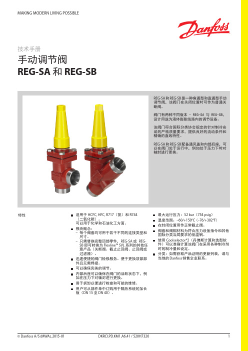
REG-SA 15-20 和 REG-SB 15-20
∆P = 2 bar (29 psi) ∆P = 1.5 bar (22 psi) ∆P = 1 bar (14 psi) ∆P = 0.5 bar (7 psi)
图2
4
REG-SA 15-20 和 REG-SB 15-20
B
A
2
3 25%
4
5 50%
6
7 75%
8
9 100%
䕈ⱘ䕀ࡼ ᠧᓔ
DKRCI.PD.KM1.A6.41 / 520H7320
© Danfoss A/S (MWA), 2015-01
REG-SA 型和 REG-SB 型手动调节阀 计算和选择(续) 流量系数
© Danfoss A/S (MWA), 2015-01
DKRCI.PD.KM1.A6.41 / 520H7320 3
REG-SA 型和 REG-SB 型手动调节阀 计算和选择 流量系数
Kv (Cv) 0.6 (0.70) 0.5 (0.58) 0.4 (0.46) 0.3 (0.35) 0.2 (0.23) 0.1 (0.12) 0
Danfoss自动差压式平衡阀
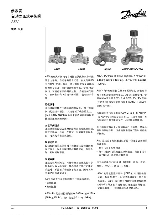
ASV-PV Plus的出厂设定为0.3bar(30kPa), 差压可在0.2bar-0.4bar(20kPa至40kPa)之间 设定。
ASV-PV出厂设定为0.1bar(10kPa),差压可 在0.05bar-0.25bar(5kPa至25kPa)之间设定。
ASV-P的差压为固定值,0.1bar(10kPa)。 ASV-PF DN50的阀门见单独样本。
2,98x1,78 G 1/16
产品编号 003L8155 003L8156 003L8157 003L8158 003L8158 003L8146 003L8147 003L8148 003L8149 003L8149 003L8143
003L8141
003L8145
003L8152
003L8153
ASV - PV 的差压控制范围为 0.05bar 至 0.25bar (5kPa至25kPa)。出厂设定为0.1bar(10kPa)。
SIBC
VD.A1.T2.41 C Danfoss 11/03
1
参数表
订货
SIBC
自动差压式平衡阀 ASV
型号
DN
mk3v/sh
内螺纹 ISO7 / 1
产品编号
15
15
1.6
R p 1/2
003L7 601
20
2.5
R p 3/4
003L7 602
25
4.0
R p1
003L7 603
32
6.3
R p1 1/4
003L7 604
40
10
R p1 1/2
003L7 605
型号
内螺纹 ISO228 / 1
G 1/2A
Danfoss热力膨胀阀样本参数
Danfoss A/S (RC-CM/hbs), 10 - 2002
RK0YP102
3
Introduction
Thermostatic expansion valves for ammonia type TEA
Thermostatic expansion valves regulate the injection of refrigerant liquid into evaporators. Injection is controlled by the refrigerant superheat.
Thermostatic injection valves, type TEAT
Introduction .............................................................................................................................. 11 Materials .................................................................................................................................. 11 Technical data .......................................................................................................................... 11 Identification ............................................................................................................................. 11 Ordering TEAT ......................................................................................................................... 12 Rated capacity in kW ............................................................................................................... 12 Extended capacities in kW ....................................................................................................... 13 Design/Function ....................................................................................................................... 13 Dimensions and weights .......................................................................................................... 14
丹佛斯EVR系列电磁阀样本

EVR is a direct or servo operated solenoid valve for liquid, suction, and hot gas lines with fluorinated refrigerants.EVR valves are supplied complete or as separate components, i.e. valve body, coil and flanges, if required, can be ordered separately.y Complete range of solenoid valvesfor refrigeration, freezing and air conditioning planty Supplied in versions normally closed (NC) and normally open (NO) with de-energized coily Wide choice of coils for AC and DCy Suitable for all fluorinated refrigerants, including flammable refrigerantsy Designed for media temperatures up to 105 °C y MOPD up to 25 bar with 12 W coily Flare connections up to 5/8iny Solder connections up to 2 1/8iny Extended ends on solder versions make the installation easy. It is not necessary to dismantle the valve when soldering iny Available in flare, solder and flange connection versionsFeaturesDet norske Veritas, DNVPressure Equipment Directive (PED) 97/23/EC Low Voltage Directive (LVD) 2006/95/EC Polski Rejestr Statków, Polen Maritime Register of Shipping, MRS Versions with UL approvalcan be supplied to order.ApprovalsData sheet Solenoid valve, types EVR 2 − EVR 40 NC/NOTechnical data1) MOPD (Max. Opening Pressure Differential) for media in gas form is approx. 1 bar greater.2)Min. diff. pressure 0.07 bar is needed to stay open.RefrigerantsR22/R407C, R404A/R507, R410A, R134a, R407A, R23, R32, R290, R600, and R600a. For other refrigerants, contact Danfoss.Special note for R32, R290, R600, and R600a : Use only for system in compliance withstandard EN13463-1. Ignition risk is evaluated inaccordance with standard EN13463-1.Only EVR 2 - EVR 20 with solder connections andwithout manual stem can be applied in systemswith R32, R290, R600, and R600a as the workingfluid. For countries where safety standards are not an indispensable part of the safety system Danfoss recommends the installer to seek third partyapproval for systems containing R32, R290, R600, Note, please follow specific selection criteria stated in the datasheet for these particular refrigerants.Temperature of medium-40 – 105 °C with 10 W or 12 W coil.Max. 130 °C during defrosting.Ambient temperature and enclosure for coil See separate data sheet for coils and ATEX coils.Capacity The capacity of the valve depends on the flow direction, see K v values from the table.The K v value is the water flow in [m 3/h] at a pressure drop across valve of 1 bar, ρ = 1000 kg/m 3.See extended capacity tables later in this datasheet.Table of contentsTechnical data.............................................................................................................................................................................2Rated capacity [kW] .................................................................................................................................................................3Ordering .......................................................................................................................................................................................4Capacity, Liquid .........................................................................................................................................................................7Capacity, Suction .....................................................................................................................................................................11Capacity, Hot gas ....................................................................................................................................................................19Design ........................................................................................................................................................................................40Function.....................................................................................................................................................................................42Material specifications .........................................................................................................................................................43Dimensions and weights .. (45)Data sheet Solenoid valve, types EVR 2 − EVR 40 NC/NORated liquid and suction vapour capacity is based on evaporating temperature t e = -10 °C, liquid temperature ahead of valve t l = 25 °C, pressure drop in valve ∆p = 0.15 bar.Rated hot gas capacity is based on condensing temperature t c = 40 °C, pressure drop across valve ∆p = 0.8 bar, hot gas temperature t h = 65 °C,and subcooling of refrigerant ∆tsub = 4 K.Rated capacity [kW]Data sheet Solenoid valve, types EVR 2 − EVR 40 NC/NOOrdering (continued)EVR solder connections, Normally Closed (NC) - separate valve bodiesData sheet Solenoid valve, types EVR 2 − EVR 40 NC/NOThe normal range of coils can be used for the NO valves, with the exception of the double frequency versions of 110 V,50/60 Hz and 220 V, 50/60 Hz.Ordering (continued)EVR solder connections, Normally Open (NO) - separate valve bodiesValve bodies are supplied without flare nuts. Separate flare nuts:– 1/4 in or 6 mm, code no. 011L1101 – 3/8 in or 10 mm, code no. 011L1135 – 1/2 in or 12 mm, code no. 011L1103 – 5/8 in or 16 mm, code no. 011L1167OrderingEVR flare connections, Normally Closed (NC) - separate valve bodiesSee separate data sheet for coils.The normal range of coils can be used for the NO valves, with the exception of the double frequency versions of 110 V, 50/60 Hz and 220 V, 50/60 Hz.Data sheet Solenoid valve, types EVR 2 − EVR 40 NC/NO Ordering (continued)Separate valve bodies, normally closed (NC)See separate data sheet for coils.Flange setsAccessoriesEVR 15 without manual operation, code no. 032F1224½ in weld flange set, code no. 027N1115+ coil with terminal box, 220 V, 50 Hz, code no. 018F6701See separate data sheet for coils.ExampleCapacities are based on:– liquid temperaturet l = 25 °C ahead of valve, – evaporating temperature t e = -10 °C, superheat 0 K.Correction factorsWhen sizing valves, the plant capacity must be multiplied by a correction factor depending on liquid temperature t l ahead of valve/evaporator.When the corrected capacity is known,the selection can be made from the table.R22/R407CCorrection factors based on liquid temperature t lLiquidCapacities are based on:– liquid temperaturet l = 25 °C ahead of valve, – evaporating temperature t e = -10 °C, superheat 0 K.Correction factorsWhen sizing valves, the plant capacity must be multiplied by a correction factor depending on liquid temperature t l ahead of valve/evaporator.When the corrected capacity is known,the selection can be made from the table.Correction factors based on liquid temperature t lR404A/R507Liquid (continued)Capacities are based on:– liquid temperaturet l = 25 °C ahead of valve, – evaporating temperature t e = -10 °C, superheat 0 K.Correction factorsWhen sizing valves, the plant capacity must be multiplied by a correction factor depending on liquid temperature t l ahead of valve/evaporator.When the corrected capacity is known,the selection can be made from the table.Correction factors based on liquid temperature t lR290Liquid (continued)Data sheet Solenoid valve, types EVR 2 − EVR 40 NC/NOCapacities are based on:– liquid temperaturet l = 25 °C ahead of valve, – evaporating temperature t e = -10 °C, superheat 0 K.Correction factorsWhen sizing valves, the plant capacity must be multiplied by a correction factor depending on liquid temperature t l ahead of valve/evaporator.When the corrected capacity is known,the selection can be made from the table.Correction factors based on liquid temperature t lR600Capacity Liquid (continued)R22/R407CCorrection factorsWhen sizing valves, the evaporator capacity must be multiplied by a correction factor depending on liquid temperature t l ahead of expansion valve.When the corrected capacity is known, the selection can be made from the table.Correction factors for evaporating temperature tlCapacities are based on liquid temperature t l = 25 °C ahead of evaporator. The table values refer to the evaporator capacity and are given as a function ofevaporating temperature t e and pressure drop ∆p across valve.Capacities are based on dry, saturated vapour ahead of valve.During operation with superheated vapour ahead of valve, the capacities are reduced by 4% for each 10 K superheat.Capacity SuctionCapacities are based on liquid temperature t l = 25 °C ahead of evaporator. The table values refer to the evaporator capacity and are given as a function ofevaporating temperature t e and pressure drop ∆p across valve.Capacities are based on dry, saturated vapour ahead of valve.During operation with superheated vapour ahead of valve, the capacities are reduced by 4% for each 10 K superheat.Correction factors based on evaporating temperature t lCorrection factorsWhen sizing valves, the evaporator capacity must be multiplied by a correction factor depending on liquid temperature t l ahead of expansion valve.When the corrected capacity is known,the selection can be made from the table.R134aCapacity Suction(continued)Correction factors based on evaporating temperature t lCorrection factors When sizing valves, the evaporator capacity must be multiplied by a correction factor depending on liquid temperature t l ahead of expansion valve.When the corrected capacity is known,the selection can be made from the table.R404A/R507Capacities are based on liquid temperature t l = 25 °C ahead of evaporator. The table values refer to the evaporator capacity and are given as a function ofevaporating temperature t e and pressure drop ∆p across valve.Capacities are based on dry, saturated vapour ahead of valve.During operation with superheated vapour ahead of valve, the capacities are reduced by 4% for each 10 K superheat.Capacity Suction(continued)Correction factors based on evaporating temperature t lCorrection factorsWhen sizing valves, the evaporator capacity must be multiplied by a correction factor depending on liquid temperature t l ahead of expansion valve.When the corrected capacity is known,the selection can be made from the table.R32Capacities are based on liquid temperature t l = 25 °C ahead of evaporator. The table values refer to the evaporator capacity and are given as a function ofevaporating temperature t e and pressure drop ∆p across valve.Capacities are based on dry, saturated vapour ahead of valve.During operation with superheated vapour ahead of valve, the capacities are reduced by 4% for each 10 K superheat.Capacity Suction(continued)Correction factors based on evaporating temperature t lCorrection factorsWhen sizing valves, the evaporator capacity must be multiplied by a correction factor depending on liquid temperature t l ahead of expansion valve.When the corrected capacity is known,the selection can be made from the table.R290Capacities are based on liquid temperature t l = 25 °C ahead of evaporator. The table values refer to the evaporator capacity and are given as a function ofevaporating temperature t e and pressure drop ∆p across valve.Capacities are based on dry, saturated vapour ahead of valve.During operation with superheated vapour ahead of valve, the capacities are reduced by 4% for each 10 K superheat.Capacity Suction(continued)Correction factors based on evaporating temperature t lCorrection factorsWhen sizing valves, the evaporator capacity must be multiplied by a correction factor depending on liquid temperature t l ahead of expansion valve.When the corrected capacity is known,the selection can be made from the table.R600Capacities are based on liquid temperature t l = 25 °C ahead of evaporator. The table values refer to the evaporator capacity and are given as a function ofevaporating temperature t e and pressure drop ∆p across valve.Capacities are based on dry, saturated vapour ahead of valve.During operation with superheated vapour ahead of valve, the capacities are reduced by 4% for each 10 K superheat.Capacity Suction(continued)Correction factors based on evaporating temperature t lCorrection factorsWhen sizing valves, the evaporator capacity must be multiplied by a correction factor depending on liquid temperature t l ahead of expansion valve.When the corrected capacity is known,the selection can be made from the table.R600aCapacities are based on liquid temperature t l = 25 °C ahead of evaporator. The table values refer to the evaporator capacity and are given as a function ofevaporating temperature t e and pressure drop ∆p across valve.Capacities are based on dry, saturated vapour ahead of valve.During operation with superheated vapour ahead of valve, the capacities are reduced by 4% for each 10 K superheat.Capacity Suction(continued)Hot gas defrostingWith hot gas defrosting it is not normally possible to select a valve from condensing temperature t c and evaporating temperature t e .This is because the pressure in the evaporator as a rule quickly rises to a value near that of the condensing pressure. It remains at this value until the defrosting is finished.In most cases therefore, the valve will be selected from condensing temperature t c and pressure drop ∆p across the valve, as shown in the example for heat recovery.Heat recoveryThe following is given: y Refrigerant = R22/R407Cy Evaporating temperature t e = -30 °C y Condensing temperature t c = 40 °Cy Hot gas temperature ahead of valve t h = 85 °Cy Heat recovery condenser yield Q h = 8 kWThe capacity table for R22/R407C with t c = 40 °C gives the capacity for an EVR 10 as 8.9 kW, when pressure drop ∆p is 0.2 bar.The required capacity is calculated as :Q table = f evaporator x f hot_temperature x Q hThe correction factor for t e = -30 °C is given in the table as 0.95.The correction for hot gas temperature t h = 85 °C has been calculated as 4% which corresponds to a factor of 1.04.Q h must be corrected with factors found: With ∆p = 0.2 baris Q h = 8.71 x 0.95 x 1.04 = 8.6 kW.With ∆p = 0.1 bar, Q h becomes only 6.19 x 0.95 x 1.04 = 6.1 kW.An EVR 6 would also be able to give the required capacity, but with ∆p at approx. 1 bar. The EVR 6 is therefore too small.The EVR 15 is so large that it is doubtful whether the necessary ∆p of approx. 0.1 bar could be obtained.An EVR 15 would therefore be too large.Result: An EVR 10 is the correct valve for the given conditions.Capacity Suction (continued)R22/R407CAn increase in hot gas temperature t h of 10 K, based on t h = t c +25 °C, reduces valve capacity approx. 2% and vice versa.A change in evaporating temperature t e changes valve capacity; see correction factor table below.Correction factorsWhen sizing valves, the table value mustbe multiplied by a correction factor depending on evaporating temperature t e .Correction factors for evaporating temperature teCapacity Hot gasAn increase in hot gas temperature t h of 10 K, based on t h = t c 25 °C, reduces valve capacity approx. 2% and vice versa.A change in evaporating temperature t e changes valve capacity; see correction factor table below.Correction factorsWhen sizing valves, the table value must be multiplied by a correction factor depending on evaporating temperature t e .Correction factors for evaporating temperature teR22/R407C (continued)Capacity Hot gas(continued)Correction factorsWhen sizing valves, the table value must be multiplied by a correction factor depending on evaporating temperature t e .Correction factors for evaporating temperature t eR134aAn increase in hot gas temperature t h of 10 K, based on t h = t c 25 °C, reduces valve capacity approx. 2% and vice versa.A change in evaporating temperature t e changes valve capacity; see correction factor table below.Capacity Hot gas(continued)Correction factorsWhen sizing valves, the table value must be multiplied by a correction factor depending on evaporating temperature t e .Correction factors for evaporating temperature t eR134a (continued)An increase in hot gas temperature t h of 10 K, based on t h = t c 25 °C, reduces valve capacity approx. 2% and vice versa.A change in evaporating temperature t e changes valve capacity; see correction factor table below.Capacity Hot gas(continued)Correction factorsWhen sizing valves, the table value must be multiplied by a correction factor depending on evaporating temperature t e .Correction factors for evaporating temperature teR404A/R507An increase in hot gas temperature t h of 10 K, based on t h = t c 25 °C, reduces valve capacity approx. 2% and vice versa.A change in evaporating temperature t e changes valve capacity; see correction factor table below.Capacity Hot gas(continued)Correction factorsWhen sizing valves, the table value must be multiplied by a correction factor depending on evaporating temperature t e .Correction factors for evaporating temperature teR404A/R507 (continued)An increase in hot gas temperature t h of 10 K, based on t h = t c 25 °C, reduces valve capacity approx. 2% and vice versa.A change in evaporating temperature t e changes valve capacity; see correction factor table below.Capacity Hot gas(continued)Correction factorsWhen sizing valves, the table value must be multiplied by a correction factor depending on evaporating temperature t e .Correction factors for evaporating temperature teR32An increase in hot gas temperature t h of 10 K, based on t h = t c 25 °C, reduces valve capacity approx. 2% and vice versa.A change in evaporating temperature t e changes valve capacity; see correction factor table below.Capacity Hot gas(continued)Correction factorsWhen sizing valves, the table value must be multiplied by a correction factor depending on evaporating temperature t e .Correction factors for evaporating temperature teR32 (continued)An increase in hot gas temperature t h of 10 K, based on t h = t c 25 °C, reduces valve capacity approx. 2% and vice versa.A change in evaporating temperature t e changes valve capacity; see correction factor table below.Capacity Hot gas(continued)Correction factorsWhen sizing valves, the table value must be multiplied by a correction factor depending on evaporating temperature t e .Correction factors for evaporating temperature teR290An increase in hot gas temperature t h of 10 K, based on t h = t c 25 °C, reduces valve capacity approx. 2% and vice versa.A change in evaporating temperature t e changes valve capacity; see correction factor table below.Capacity Hot gas(continued)Correction factorsWhen sizing valves, the table value must be multiplied by a correction factor depending on evaporating temperature t e .Correction factors for evaporating temperature teR290 (continued)An increase in hot gas temperature t h of 10 K, based on t h = t c 25 °C, reduces valve capacity approx. 2% and vice versa.A change in evaporating temperature t e changes valve capacity; see correction factor table below.Capacity Hot gas(continued)Correction factorsWhen sizing valves, the table value must be multiplied by a correction factor depending on evaporating temperature t e .Correction factors for evaporating temperature teR600An increase in hot gas temperature t h of 10 K, based on t h = t c 25 °C, reduces valve capacity approx. 2% and vice versa.A change in evaporating temperature t e changes valve capacity; see correction factor table below.Capacity Hot gas(continued)Correction factorsWhen sizing valves, the table value must be multiplied by a correction factor depending on evaporating temperature t e .Correction factors for evaporating temperature teR600 (continued)An increase in hot gas temperature t h of 10 K, based on t h = t c 25 °C, reduces valve capacity approx. 2% and vice versa.A change in evaporating temperature t e changes valve capacity; see correction factor table below.Capacity Hot gas(continued)Correction factorsWhen sizing valves, the table value must be multiplied by a correction factor depending on evaporating temperature t e .Correction factors for evaporating temperature teR600aAn increase in hot gas temperature t h of 10 K, based on t h = t c 25 °C, reduces valve capacity approx. 2% and vice versa.A change in evaporating temperature t e changes valve capacity; see correction factor table below.Capacity Hot gas(continued)Correction factorsWhen sizing valves, the table value must be multiplied by a correction factor depending on evaporating temperature t e .Correction factors for evaporating temperature teR600a (continued)An increase in hot gas temperature t h of 10 K, based on t h = t c 25 °C, reduces valve capacity approx. 2% and vice versa.A change in evaporating temperature t e changes valve capacity; see correction factor table below.Capacity Hot gas(continued)R22/R407CCapacity Hot gas (continued)An increase in hot gas temperature t h of 10 K, based on t h = t c 25 °C, reduces valve capacity approx. 2% and vice versa.A change in evaporating temperature t e changes valve capacity; see correction factor table below.R134aCapacity Hot gas (continued)An increase in hot gas temperature t h of 10 K, based on t h = t c 25 °C, reduces valve capacity approx. 2% and vice versa.A change in evaporating temperature t e changes valve capacity; see correction factor table below.R404A/R507Capacity Hot gas (continued)An increase in hot gas temperature t h of 10 K, based on t h = t c 25 °C, reduces valve capacity approx. 2% and vice versa.A change in evaporating temperature t e changes valve capacity; see correction factor table below.R32Capacity Hot gas (continued)An increase in hot gas temperature t h of 10 K, based on t h = t c 25 °C, reduces valve capacity approx. 2% and vice versa.A change in evaporating temperature t e changes valve capacity; see correction factor table below.R290Capacity Hot gas (continued)An increase in hot gas temperature t h of 10 K, based on t h = t c 25 °C, reduces valve capacity approx. 2% and vice versa.A change in evaporating temperature t e changes valve capacity; see correction factor table below.R600Capacity Hot gas (continued)An increase in hot gas temperature t h of 10 K, based on t h = t c 25 °C, reduces valve capacity approx. 2% and vice versa.A change in evaporating temperature t e changes valve capacity; see correction factor table below.R600aCapacity Hot gas (continued)An increase in hot gas temperature t h of 10 K, based on t h = t c 25 °C, reduces valve capacity approx. 2% and vice versa.A change in evaporating temperature t e changes valve capacity; see correction factor table below.Design4. Coil16. Armature 18. V alve plate/Pilot valve plate 20. Earth terminal 24. C onnection for flexiblesteel hose 28. Gasket 29. Pilot orifice 30. O-ring 36. DIN plug 37. D IN socket (to DIN 43650) 40. P rotective cap/Terminal box 43. Valve cover 44. O-ring45. Valve cover gasket 49. Valve body73. Equalization hole 80. D iaphragm/Servo piston 83. Valve seat90. Mounting holeNote :The drawings are only representative.4. Coil16. Armature 18. V alve plate/ Pilot valve plate 20. Earth terminal 28. Gasket 29. Pilot orifice 30. O-ring 31. Piston ring 36. DIN plug 37. D IN socket (to DIN 43650) 40. P rotective cap/ Terminal box 43. Valve cover 44. O-ring45. Valve cover gasket 49. Valve body 51. Threaded plug 53. M anual operation spindle 73. Equalization hole 74. Main channel 75. Pilot channel76. Compression spring 80. D iaphragm / Servo piston 83. Valve seat84. Main valve plateEVR 32 and EVR 40 (NC)EVR 25 (NC)Design (continued)Note :The drawings are only representative.Function EVR solenoid valves are designedon two different principles:1. Direct operation2. Servo operation1. Direct operationEVR 2 – EVR 3 are direct operated. The valves open directly for full flow when the armature (16) moves up into the magnetic field of the coil. This means that the valves operate with a min differential pressure of 0 bar.The valve plate (18) is fitted directly on the armature (16).Inlet pressure acts from above on the armature and the valve plate. Thus, inlet pressure and spring force act to close the valve when the coil is currentless.2. Servo operationEVR 6 – EVR 22 are servo operated with a "floating" diaphragm (80). The pilot orifice (29) of stainless steel is placed in the centre of the diaphragm. The pilot valve plate (18) is fitted directly to the armature (16). When the coil is currentless, the main orifice and pilot orifice are closed. The pilot orifice and main orifice are held closed by the armature spring force and the differential pressure between inlet andoutlet sides.When current is applied to the coil the armature is drawn up into the magnetic field and opens the pilot orifice. This relieves the pressure above the diaphragm, i.e. the space above the diaphragm becomes connected to the outlet side of the valve. The differential pressure between inlet and outlet sides then presses the diaphragm away from the main orifice and opens it for full flow. Therefore a certain minimum differential pressure is necessary to open the valve and keep it open. For EVR 6 – EVR 22 valves this differential pressure is 0.05 bar.When current is switched off, the pilot orifice closes. Via the equalization holes (73) in the diaphragm, the pressure above the diaphragm then rises to the same value as the inlet pressure and the diaphragm closes the main orifice.EVR 25, EVR 32 and EVR 40 are servo operated piston valves. The valves are closed with currentless coil. The servo piston (80) with main valve plate (84) closes against the valve seat (83) by means of the differential pressure between inlet and outlet side of the valve and the force of the compression spring (76). When current to the coil is switched on, the pilot orifice (29) opens. This relieves the pressure on the piston spring side of the valve. The differential pressure will then open the valve. The minimum differential pressure needed for full opening of the valves is 0.2 bar. EVR (NO) has the opposite function to EVR (NC), i.e. it is open with de-energised coil.EVR (NO) is available with servo operation only.Material specifications EVR 2 – EVR 25Note:The drawings are only representative.Material specifications (continued)EVR 32 – EVR 40Note :The drawing is only representative.With DIN plugs coilWith cable connection coilNet weight of coil 10 W: approx. 0.3 kg12 and 20 W: approx. 0.5 kgWith terminal box coilDimensions [mm] and weights [kg]EVR 2 – EVR 6 NC/NO, solder connection For 3D models, visit /products/categories/Note :The drawings are only representative.。
丹佛斯Danfoss动态压差平衡阀ASV参数表-水力平衡
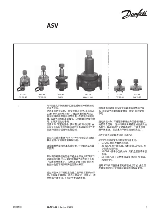
图 4 ASV用于地板采暖系统中分集水器前
ASV 阀用于地板采暖系统。为实现对每个环路的 流量限制,应将带有预设定的分集水器与 ASV-PV 阀提供的恒定压差控制配合使用。或者通过使用
具有设定功能 ASV-I 实现对整个分集水器的流量 限制。
如需不同的设定压差,ASV-PV 的设定压差具有数 个的可选范围。由于尺寸紧凑,ASV 动态压差平衡 阀易于安装于挂墙的分集水器安装盒内。
型号
备注
螺纹尾管(1 件)
焊接尾管(1 件)
连接至管道 R½ R¾ R1 R 1¼ R 1½
R2
DN 15 DN 20 DN 25 DN 32 DN 40
DN 50
注意: ASV-PV DN 50 (2½”) 和 ASV-I/M DN 50 (2¼”) 的接头口径不同。 1) 与 ASV-PV DN 50 阀配套使用 2) 与 ASV-I 和 ASV-M DN 50 配套使用。
ASV-P 阀为固定压差设定(10KPa)。
ASV-PV 阀可设定为不同范围压差设定: • 5-25KPa 常用在散热器系统, • 20-40KPa 用于散热器、风机盘管、冷吊顶、及
小型换热站系统, • 35-75KPa 用于小型换热站、风机盘管及冷吊顶
系统, • 60-100KPa 用于大的末端设备(例如:空调箱、
22
VD.A1.T8.41 © Danfoss 07/2013
DH-SMT/SI
DH-SMT/SI
VD.A1.T8.41 © Danfoss 07/2013
3
参数表 描述 / 应用 (续)
动态压差平衡阀 ASV
参数表
保温材料
图 +5 ASV 用于风机盘管系统
丹佛斯Danfoss静态平衡阀MSV-BD参数表-水力平衡

2
VDB4C341 © Danfoss03/2012
HEC-HB
参数表
静态平衡阀 LENO™ MSV-BD
压紧连接件(用于外螺纹阀) 钢/铜管 G ¾ x 15 G ¾ x 16 G ¾ x 18 G 1 x 18 尺寸 产品编号 013G4125 013G4126 013G4128 013U0134
5
5.封条—保护设定值(如图所示)。
测量
当水流过 MSV-BD调节阀时, 使用丹佛斯PFM 3000/4000 或其它测量仪可以对其流量进行测 量。 LENO™ MSV-BD调节阀提供两个测试头,适 合直径3mm的测试探针。支架成对,可以同时 连接这两个测试头。 注意:如使用非丹佛斯测量仪器,需对结果进 行修正,相关信息请联系丹佛斯。 测量流量的过程: 1.选择流量测量 2.选择阀门品牌 3.选择阀门类型和尺寸 4.输入预调节值 5.连接阀和测量仪仪器 6.校准静态压力 7.测量流量
kv = Qm3/h √∆pi bar = 2.0 √0.20 = 4.5 m3/h
Leno™ MSV-BD ∆p r ∆p m
7
∆p i
M
∆p a
丹佛斯Danfoss生活热水循环系统多功能恒温阀MTCV-水力平衡
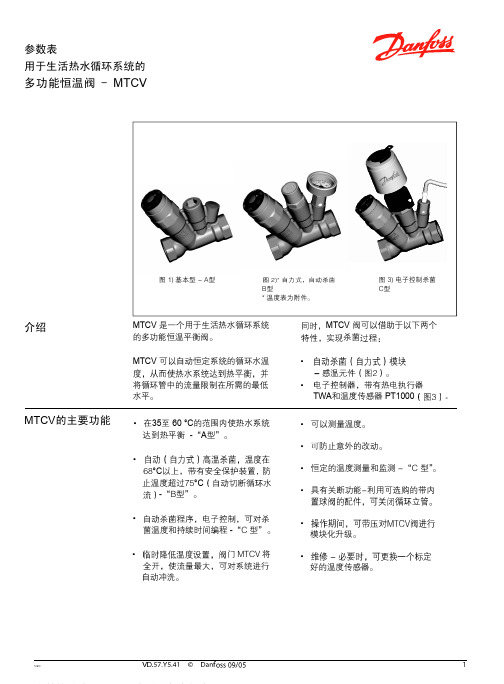
多功能恒温阀 - MTCV
50 ˚C下 在 35 ˚C下
在 60˚C下
流 量 水 温 温 度 ˚C
预设
预设
预设
预设
预设
预设
水温 ˚C
流量温度 ˚C
B型 C型
数据表 计算举例
多功能恒温阀 - MTCV
8 个立管进行计算。
VD.57.X1.02
•
q1 =10
*
*
- 管路的尺寸 - 绝热层的材料 - 装管子处的环境温度 - 绝热层的效率和条件
•
Tsup = 55 °C
•
∆T= 5 K
•
•
l = 10 m
•
I 基本操作
• 每个立管中热量损失的计算
Qr
Qh
Qr = l立管x q = (10+10) x10 = 200 m
Qh= l 水平 x q = 10 x 10= 100 m
•表3
立管
立管中 Qr
顶部 Qh
热量损失 每一部分的 总的损失
ΣQ 总
阀 – 基本型A型
产品编号
阀体 ................................................Rg 5 O型密封圈 ...................................EPDM
. 不锈钢
高温杀菌模块 -B型
描述
产品编号
ESMB PT1000用插座
CCR2控制器
• 模块化升级。
• 好的温度传感器。
数据表 功能
多功能恒温阀 - MTCV
1-A型。
当水温比设定值高 5°
MTCV 是一种自力式比例控制的恒温控制
丹佛斯制冷空调配件 (5)

如果要求更高的调节精度和较低的吸入压力,或 者如果在 CPCE 出口和吸入压力之间有较高的压 降,则可以使用 CPCE 容量调节阀来替代 KVC。
压力调节阀
Ak0_0002
KVC 也可以安装在压缩机排放管的旁路管路中, 阀的出口连接到膨胀阀和蒸发器之间某一点。
这种布局可以用于使用多个并联耦合式压缩机并 且未使用分液器的冷液器中。
© Danfoss A/S (RA Marketing/MWA), 04-2007 DKRCC.PF.000.G1.41 / 520H1981
37
装配说明� KVR 冷凝压力调节阀
�压�力�调�节�阀
KVR 通常安装在空冷式冷凝器和接收器之间。 KVR 可以保持空冷式冷凝器中的恒压。入口压力 (冷凝压力)升高时 KVR 将打开。 KVR 与 KVD 或 NRD 一起确保在不同的工作条件 下接收器中具有足够高的液压。 KVR 蒸发压力调节阀带有压力计接头,可以在设 置冷凝压力时使用。
装配说明� 目录�
�压�力�调�节�阀
页�码� 应用 . . . . . . . . . . . . . . . . . . . . . . . . . . . . . . . . . . . . . . . . . . . . . . . . . . . . . . . . . . . . . . . . . . . . . . . . . . . . . . . . . . . . . . . . . . . . . 37
Ak0_0031
蒸发压力调节阀安装在蒸发器后的吸入管路中, 用于调节包含一个或多个蒸发器和一个压缩机的 制冷系统的蒸发压力。 在这样的制冷系统中(在不同蒸发压力下运 行),KVP 被安装在具有最高蒸发压力的蒸发器 之后。 每个蒸发器由一个液体管路中的电磁阀启动。每 个压缩机由抽气功能中的一个压力开关控制。吸 入侧的最大压力对应于最低的室温。
丹佛斯电动调节阀

高效节能方案
提供全面的节能解决方案,帮助企 业优化能源利用,降低运营成本。
符合环保要求
节能性符合国家环保要求,有助于 企业实现绿色可持续发展。
04
使用与维护
使用方法
开启与关闭
在接通电源后,按下控制面板上的开启或关闭按钮,阀门即可动 作。
调节流量
通过控制面板上的调节旋钮或输入控制信号,可以调节阀门的开 度,从而控制流量。
高效节能
高效节能技术将进一步应用于电动调节阀,降低 能耗,提高能源利用效率。
3
可靠性提升
通过材料、工艺和设计的改进,提高电动调节阀 的可靠性和寿命,减少维护和更换的频率。
市场前景分析
市场需求增长
随着工业自动化程度的提高和节能减排的需 求,电动调节阀的市场需求将持续增长。
竞争格局变化
随着新技术的出现和市场需求的增长,电动调节阀 行业的竞争格局将发生变化,优质企业将获得更多 市场份额。
阀门无法动作
可能是电源故障或电机损坏,应检查电源和电机 是否正常工作。
阀门泄漏
可能是密封件老化或损坏,应更换密封件。
阀门卡死
可能是润滑不良或异物堵塞,应加注润滑油或清 除异物。
05
丹佛斯电动调节阀与其他调节阀 的比较
与气动调节阀的比较
能源效率
丹佛斯电动调节阀通常比气动调节阀更节能,因为它们不需要压缩 空气或气体,从而减少了能源消耗。
维护成本
气动调节阀需要定期更换空气过滤器和密封件,而电动调节阀的维 护成本相对较低,因为它们结构简单且部件较少。
控制精度
气动调节阀在控制精度方面可能不如电动调节阀,因为气体的压力和 流量可能会受到环境因素的影响,而电动调节阀的控制精度更高。
丹佛斯Danfoss动态压差平衡阀ASV参数表-水力平衡
产品编号
003L7621 003L7622 003L7623 003L7624 003L7625
型号
外螺纹 ISO 228/1
G¾A G1A G 1¼ A G 1½ A G 1¾ A
产品编号
003L7626 003L7627 003L7628 003L7629 003L7630
ASV-PV 压差平衡阀包括 1.5m长的脉冲管(G / A)和泄水龙头(G / A)
搭配 ASV-M /ASV-I 或 MSV-F2 阀门时有两种基本 配置:
图 1 ASV-PV 的设置 = p立管
图 2 ASV-PV 的设置 = ∆p立管 + ∆pi
- 将配套阀门内置于 ASV-PV 所控制环路之外。 当末端阀门带有预设定功能时候(例如散热器 恒温阀),此时无需再立管上进行流量限制。 DN 15 至 DN 50, 可使用 ASV-M (图 1)。 DN 65 至 DN 100,可使用 MSV-F2 作为配套阀门, 连接到控制回路外部。 此时立管的流量限 制虽不可用,但对立管,其压差控制仍然起作 用。
ASV-P 阀为固定压差设定(10KPa)。
ASV-PV 阀可设定为不同范围压差设定: • 5-25KPa 常用在散热器系统, • 20-40KPa 用于散热器、风机盘管、冷吊顶、及
小型换热站系统, • 35-75KPa 用于小型换热站、风机盘管及冷吊顶
系统, • 60-100KPa 用于大的末端设备(例如:空调箱、
恒定压差控制与带有预设定功能的控制阀联用, 可实现流量限制功能。或可将ASV-PV与带有设定 功能的阀门ASV-I/MSV-F2联用,以实现流量限制 功能。
描述
使用 EPS 聚苯乙烯基包装的阀门可以持续工作在
丹佛斯压力传感器型号对应表

CN
0
CN
0
CN
0
CN
0
CN
0
CN
0
CN
0
060G1270 060G1271 060G1286 060G1297 060G1321 060G1323 060G1325 060G1327 060G1328 060G1347 060G1348 060G1349 060G1366 060G1367 060G1368 060G1369 060G1370 060G1371 060G1372 060G1401 060G1404 060G1405 060G1406 060G1407 060G1408 060G1409 060G1411 060G1412 060G1413 060G1414 060G1415 060G1429 060G1430 060G1435 060G1436 060G1437 060G1438 060G1441 060G1444 060G1446 060G1447 060G1452 060G1454 060G1455 060G1456 060G1457 060G1461 060G1462 060G1463 060G1464 060G1465 060G1466 060G1467 060G1468 060G1469 060G1470
0
CN
0
CN
0
CN
0
CN
0
CN
0
CN
0
CN
0
060G1471 060G1472 060G1473 060G1474 060G1475 060G1476 060G1477 060G1485 060G1489 060G1490 060G1492 060G1516 060G1517 060G1533 060G1534 060G1539 060G1540 060G1541 060G1542 060G1543 060G1546 060G1560 060G1563 060G1569 060G1572 060G1585 060G1600 060G1604 060G1605 060G1607 060G1608 060G1609 060G1611 060G1612 060G1613 060G1614 060G1615 060G1616 060G1617 060G1626 060G1631 060G1634 060G1637 060G1642 060G1645 060G1646 060G1648 060G1650 060G1654 060G1655 060G1656 060G1665 060G1666 060G1676 060G1677
丹福斯(Danfoss)方向式阀门产品说明书
Revised 10/01/88I–3557-SWet Armature Solenoid Operated Directional ValveDG4S*-01*A-W(3)-*-50Service GuideVickers by Danfoss®Directional ValvesAX439457235961en-000101’d) (F3 Viton - 5 req’d)Model CodePrinted in U.S.A.For satisfactory service life of these components, use full ow ltration to provide uid which meets ISO cleanliness code 20/18/15 or cleane r. Selections from Danfoss OF P, OFR, and OFRS series are recommended.Danfoss Power Solutions is a global manufacturer and supplier of high-quality hydraulic and electric components. We specialize in providing state-of-the-art technology and solutions marine sector. Building on our extensive applications expertise, we work closely with you to ensure exceptional performance for a broad range of applications. We help you and other customers around the world speed up system development, reduce costs and bring vehicles and vessels to market faster.Danfoss Power Solutions – your strongest partner in mobile hydraulics and mobile Go to for further product information.outstanding performance. And with an extensive network of Global Service Partners, we also provide you with comprehensive global service for all of our components.Local address:DanfossPower Solutions GmbH & Co. OHG Krokamp 35D-24539 Neumünster, Germany Phone: +49 4321 871 0DanfossPower Solutions ApS Nordborgvej 81DK-6430 Nordborg, Denmark Phone: +45 7488 2222DanfossPower Solutions (US) Company 2800 East 13th Street Ames, IA 50010, USA Phone: +1 515 239 6000DanfossPower Solutions Trading (Shanghai) Co., Ltd.Building #22, No. 1000 Jin Hai Rd Jin Qiao, Pudong New District Shanghai, China 201206Phone: +86 21 2080 6201Danfoss can accept no responsibility for possible errors in catalogues, brochures and other printed material. Danfoss reserves the right to alter its products without notice. This also applies to productsagreed.All trademarks in this material are property of the respective companies. Danfoss and the Danfoss logotype are trademarks of Danfoss A/S. All rights reserved.© Danfoss | December 2022•Cartridge valves •DCV directional control valves•Electric converters •Electric machines •Electric motors •Gear motors •Gear pumps •Hydraulic integrated circuits (HICs)•Hydrostatic motors •Hydrostatic pumps •Orbital motors •PLUS+1® controllers •PLUS+1® displays •PLUS+1® joysticks and pedals•PLUS+1® operator interfaces•PLUS+1® sensors •PLUS+1® software •PLUS+1® software services,support and training •Position controls and sensors•PVG proportional valves •Steering components and systems •TelematicsHydro-GearDaikin-Sauer-Danfoss。
丹非尔福电子过压阀值5-400 商品说明册说明书

DKRCC.PD.VD1.C6.02 / 520H8021Data sheetElectric expansion valve Type ETS 12.5 - ETS 400MAKING MODERN LIVING POSSIBLE@ Danfoss A/S (AC-MCI / sw), 2015-08Features• Precise positioning for optimal control of liquid injection.• Wide range for all common refrigerants R410A, R407C, R404A, R507, R134a, R22, R1234ze(special valves for R744 (CO 2) are available).• ETS 12.5, ETS25, ETS 50 and ETS100 provides working pressure of 45.5 bar / 660 psig and ETS 250, ETS 400 provides 34 bar / 493 psig.• Balanced design (ETS 50 – ETS 400) providing bi-flow operation as well as solenoid tight shut-off function in both flow directions.• ETS 50 and ETS 100 feature improved process and productivity due to waterless brazing i.e soldering without wet cloth for cooling.• ETS 50 – ETS 400 are all designed with built-in sight glass with moisture indicator.• Internal and external corrosion resistant design.• Low power consumption.• Cable and connector assemblies as accessories.• EKC 316A, EKC 312 and EKD316 are examples of Danfoss controllers with drivers matching the ETS needs.• For manual operation and service of ETS valves an AST-g service driver is available.ETS is a series of electric expansion valves for precise liquid injection in evaporators for air conditioning and refrigeration applications.The valve piston and linear positioning design is fully balanced, providing bi-flow feature as well as solenoid tight shut-off function in both flow directions.The valve design uses bi-polar drive providing very precise flow regulation.ETS valves are compatible with electronic control solutions from Danfoss and other manufacturers.Data sheetElectric expansion valve, type ETS2DKRCC.PD.VD1.C6.02 / 520H8021 @ Danfoss A/S (AC-MCI / sw), 2015-08Technical dataElectrical dataNOTE:Data sheet Electric expansion valve, type ETS3 @ Danfoss A/S (AC-MCI / sw), 2015-08 DKRCC.PD.VD1.C5.02 / 520H7857Designrefers to the normal flow.1. M12 connection2. Glass seal3. AST motor housing4. Stepper motor5. Bearing6. Spindle7. Cone and lead nut8. Valve seat1. M12 connector2. Glass seal3. AST motor housing4. Stepper motor5. Bearing6. Spindle7. Top Nut8. Valve piston9. Sight glass with indicator10. Valve seat11. Valve cone1. M12 connector2. Glass seal3. AST motor housing4. Stepper motor5. Bearing6. Spindle7. Top Nut8. Valve piston9. Valve seat10.Valve coneData sheetElectric expansion valve, type ETS4DKRCC.PD.VD1.C6.02 / 520H8021 @ Danfoss A/S (AC-MCI / sw), 2015-08Stepper motorswitch sequenceElectrical wiringIf the controller driving the ETS valve is from another manufacturer than Danfoss or a custom design, the following points must be considered in order to overcome potential step loss.a. To ensure total closing of the valve, thecontroller should have a function to overdrive the valve in the closing direction. It isrecommended to overdrive ten percent of the full step range at appropriate intervals.b. The amount of lost steps may increase as a function of the amount of changes of the opening degree. Such designed controller should be able to compensate the lost steps after a defined number of changes in openingdegree.At power failure the ETS valve will remain in the opening position it has at the moment of power failure, unless a safety device in the form of a battery backup is installed.ETS 50, ETS 100, ETS 250 and ETS 400 are equipped with sight glass with moistureindicator. The physical position of the piston in the valve can be checked through the sight glass. It also helps to determine the flow direction of the refrigerant in the system (ETS 50 and ETS 100).Insufficient sub cooling can produce flash gas which is visible through the sight glass. The moisture indicator in the sight glass indicates dry or wet state of the refrigerant by changing its colour.Sight glass and indicatorData sheetElectric expansion valve, type ETS5@ Danfoss A/S (AC-MCI / sw), 2015-08 DKRCC.PD.VD1.C5.02 / 520H7857Valve applicationValve operationThe ETS valves operate modulating byelectronically controlled activation of the AST stepper motor. The motor is a type 2-phase bi-polar, which stays in position, unless power pulses from a driver initiate the two discrete sets of motor stator windings for rotation in eitherdirections.The direction of the rotation of the spindledepends on the phase relationship of the power pulses. This is decisive for the travel of the piston. The motor is operating the spindle, whoserotating movements are transformed into linear motion by the transmission in the cage assembly.The AST motor housing has a glass sealed M12connection as standard, which can be connected with customized cable and plug/socket combinations.The piston design inside the ETS valve is pressure balanced, giving identical bi-flow performance capabilities and nearby identical maximum capacities.Closing the valve by overdriving, ensures that the reference number in steps is always correct.Operating the ETS series requires a controller with either 12 V DC voltage drive (5.5 W) or using chopper current drive (100 mA RMS).Danfoss EKC 316A, EKC 312 and EKD 316 are examples of qualified current controllers.there will be limitations in cable length between valve actuator and driver.Both the actual cable length, the level of EMC emission on the location and driver circuit has an impact on the actual distortion of the current to the actuator motor.For the Danfoss controllers the rule of thumb is maximum 5 m / 15 feet for EKC 316A and EKC 312 and 50 m / 150 feet for EKD 316.In order to increase max. cable lengthconsiderably, install a 10 mH filter type Danfoss AKA 211 on the four power terminals.Please contact Danfoss for further information how and when to apply this countermeasure in cases with questionable cable length.Data sheetElectric expansion valve, type ETS6DKRCC.PD.VD1.C6.02 / 520H8021 @ Danfoss A/S (AC-MCI / sw), 2015-08ETS 12.5, ETS 25Valve incl. actuatorOrderingETS 50, ETS 100Valve incl. actuatorglass1) The Rated capacity is based on: Evaporating temperature t e : 5 °C (40 °F) Liquid temperature t l : 28 °C (82 °F) Condensing temperature t c : 32 °C (90 °F)Full stroke opening in normal flow directionETS 250, ETS 400Valve incl. actuatorETS for R744 ApplicationsETS 250 and ETS 400 have integrated sight glassETS 50 and ETS 100 have integrated sight glassETS for R744 can be used for expansion as well as gas bypass.ETS for R744 Applications (PS/MWP = 45.5 bar / 660 psig)For capacities, please contact Danfoss.BData sheetElectric expansion valve, type ETS7@ Danfoss A/S (AC-MCI / sw), 2015-08 DKRCC.PD.VD1.C5.02 / 520H7857 Accessories:M12 Female Connector CableData sheetElectric expansion valve, type ETS8DKRCC.PD.VD1.C6.02 / 520H8021 @ Danfoss A/S (AC-MCI / sw), 2015-08For optimum performance, it is important to correct the evaporator capacity. Selection is also dependent on an acceptable pressure drop across the valve. The evaporator capacity must be corrected if sub cooling deviates from 4K / 7.2 °F. In order to select the correct size of ETS you will need the following information:• Refrigerant: R410A, R407C, R404A, R507, R134a, R22, R1234ze• Evaporator capacity Q e in [kW] or [TR]• Evaporating temperature t e in [°C] or [°F]• Condensing temperature t c in [°C] or [°F]• Max. acceptable pressure drop in the ETS valve in [bar] or [psi] Δp • Sub cooling Δt sub • Connection size ExampleWhen selecting the valve it may be necessary to apply a correction factor to the actual evaporator capacity. This correction factor is required when system conditions are different from tableconditions. Selection also depends on having an acceptable pressure drop across the valve. The following example illustrates correct selection of the valve.• Refrigerant: R410A• Evaporator capacity: Q e = 500 kW / 143 TR • Condensing temperature: t c = 25 °C / 77 °F • Condensing pressure: p c = 23 bar / 330 psig • Evaporating temperature: t e = +10 °C / 50 °F • Evaporating pressure: p e = 9.8 bar / 142 psig • Liquid Line Loss: p l = 0.5 bar (estimate)•Max. Pressure drop in the valve:Δp = p c - p l - p e = 23 - 0.5 - 9.8 = 12.7 bar / 184 psi • Connection size: 11/8 × 11/8 in.Valve sizingValve selectionNow select the appropriate capacity table, R410A, and choose the column for an evaporating temperature of t e = 10 °C / 50 °F.Using the corrected evaporator capacity, select a valve that provides an equivalent or greater capacity at an acceptable pressure drop across the valve of 12.7 bar / 184 psi.ETS 100 delivers 503.8 kW / 143 TR at 14 bar which is slightly higher than 12.7 bar / 184 psi pressure drop across the valve. Based on the required connection size of 11/8 in., the ETS 100 is the proper selection for this example.Step 3Step 4Determine the correction factor for sub cooling Δt sub .From the correction factors table (see below) a sub cooling of 15K / 27 °F, R410A corresponds to a factor of 1.15.Corrected evaporator capacity isQ e (Corrected) = 500 kW/1.15 = 435 kW (124 TR)Step 1Step 2ETS 100, 11/8 x 11/8 in. connection size: Single pack code no. 034G0507./businessareas/refrigerationandairconditioning/ product+selection+tools+details/coolselector.htmData sheet Electric expansion valve, type ETS9@ Danfoss A/S (AC-MCI / sw), 2015-08 DKRCC.PD.VD1.C5.02 / 520H7857 Correction for subcooling ∆tsub Note:The evaporator capacities used must be corrected if subcooling deviates from 4 K / 7.2 °F.The corrected capacity can be obtained bydividing the required evaporator capacity by the correction factor. Selections can then be madefrom the tables below.Rated Capacity [kW]Data sheetElectric expansion valve, type ETS10DKRCC.PD.VD1.C6.02 / 520H8021 @ Danfoss A/S (AC-MCI / sw), 2015-08Rated Capacity [kW]The capacities stated in the tables are for the normal flow direction. For ETS 50 and 100 specifically, the capacity in reverse flow direction varies between 90% and 125% of the capacity in normal flow direction.Rated Capacity [kW]Rated Capacity [TR] (TR = ton of refrigeration)Rated Capacity [TR](TR = ton of refrigeration)The capacities stated in the tables are for the normal flow direction. For ETS 50 and 100 specifically, the capacity in reverse flow direction varies between 90% and 125% of the capacity in normal flow direction.Rated Capacity [TR] (TR = ton of refrigeration)CapacityNormal flow directionCapacity based on: R407C T e = 5 °C / 41 °F T c = 32 °C / 89.6 °F T l = 28 °C / 82.4 °FDimensions and weights forETS 50 and ETS 100Dimensions and weights forETS 12.5 and ETS 25Dimensions and weights for ArrayETS 250 and ETS 400For further information please contact DanfossSpare partsETS 25B, ETS 50, ETS 100, ETS 250 and ETS 400 (long spindle)Gasket for all typesRelated Danfoss Products。
丹佛斯(Danfoss)温控阀 ORV DKRCI.PD.HP0.B9.02 → DKRCI.PD.
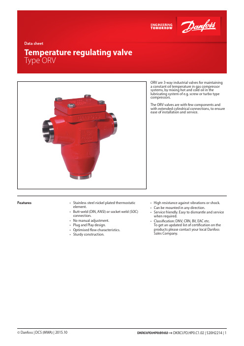
ORV are 3-way industrial valves for maintaining a constant oil temperature in gas compressor systems, by mixing hot and cold oil in the lubricating system of e.g. screw or turbo type compressors.The ORV valves are with few components and with extended cylindrical connections, to ensure ease of installation and service.Features• Stainless steel nickel plated thermostaticelement.• Butt-weld (DIN, ANSI) or socket weld (SOC)connection.• No manual adjustment.• Plug and Play design.• Optimised flow characteristics.• Sturdy construction.• High resistance against vibrations or shock.• Can be mounted in any direction.• Service friendly. Easy to dismantle and service when required.• Classification: DNV, CRN, BV, EAC etc.To get an updated list of certification on the products please contact your local Danfoss Sales Company.Technical data Oils:Applicable to all common refrigeration oils.Refrigerants:Applicable to HC, HCFC, HFC, R717 (Ammonia)and R744 (CO2).For further information please refer to installationinstruction for ORV.Temperature range:Minimum operating temperature:≥ –10°C (+14°F)Max. temperature limit based on the element temperature settings:Types Max limit43°C / 110°F77°C / 170°F49°C / 120°F82°C / 180°F60°C / 140°F93°C / 200°F77°C / 170°F110°C / 230°FPressure range:The valves are designed for a max.working pressure of 40 bar g (580 psig)Design IdentificationConnectionsAvailable with the following connections:• Butt weld DIN (EN 10220),DN 25-80 (1-3 in.)• Butt weld ANSI (B 36.10 Schedule 80),DN 25 - 40 (1 - 1½ in.)• Butt weld ANSI (B 36.10 Schedule 40),DN 50 - 80 (2 - 3 in.)• Socket Weld (ANSI B 16.11),DN 25 - 50 (1 - 2 in.)HousingMade of special, cold resistant steel approved forlow temperature operations.InstallationInstallation of the valve depends on the way itshould operate.Pressure Equipment Directive (PED)ORV valves are approved according to theEuropean standard specified in the PressureEquipment Directive and are CE marked.For further details / restrictions - see InstallationInstruction.FunctionMixing operationORV valve can work as a mixing or diverting valve. The ORV temperature regulating valve utilises the high coefficient of thermal expansion of wax to create the internal movementnecessary to have a cold and a hot inlet mixing to a common outlet. The outlet temperature will correspond to the nominal temperature of the thermostatic element.The valve house has three ports:• Port A is used for the common outlet • Port B is for the hot inlet •Port C is for the cold inletWhen the compressor unit is cold at start up, the thermostatic element will be contracted to let the full flow from port B pass until the nominal temperature (minus 5 K / 10°F ) is reached (fig. 1.1). The thermostatic element will then begin to extract to let the outlet become a mixture of hot and cold oil.When the nominal temperature is reached, the element is positioned in approximately half open position (fig. 1.2). If the temperature is reaching approximately the nominal temperature plus 5 K, the thermostatic element has been extracted to its fully open position (fig. 1.3). In this position the oil temperature will only come from the cold inlet port (C) from oil cooler.From figure 1, it can be seen how the sleeve on the element is sliding in a vertical movement. The thermostatic element is kept in position by a spring.Diverting operationDiverting operation is similar to the mixing operation. It is carried out with separation in to two of the fluid with single temperature. Due to that the temperature on the inlet is very stable fact the regulation is very smooth. The inlet temperature would correspond to the nominaltemperature of the thermostatic element.The valve house has three ports:• Port A is used for the common inlet • Port B is for the cold outlet • Port C is for the warm outletThe diverting operation otherwise is similar to the mixing operation.Application examplesExample of the system with ORV for diverting operationCapacitiesSI unitsSelection exampleOil type: Grade 68Required flow: 17 m3/hNominal oil temperature: 49°CPipe dimension: 40 mmThe upper left curve shows the viscosity of different grades of oil as a function of the temperature. The viscosity is continued into the upper right curve where the 17 m3/h must be found. The line is drawn vertically downwards into the capacity table for the ORV valve models.As shown two selections can be made:Either ORV 40 H2 with pressure drop at approx. 0.56 bar or ORV 50 H2 with pressure drop at 0.42 bar.The final selection will depend on the available pressures in the system. If the pressures are low (or can be low at certain loads) the ORV 50 H2 might be preferred. If the pressures are constantly available the pipe dimension may be taken into account and the ORV 40 H2might be preferred.CapacitiesUS unitsSelection exampleOil type: Grade 68Required flow: 75 USgal/min.Nominal oil temperature: 120°FPipe dimension: 1½”The upper left curve shows the viscosity of different grades of oil as a function of the temperature. The viscosity is continued into the upper right curve where the 75 USgal/min. must be found. The line is drawn vertically downwards into the capacity table for the ORV valve models.As shown two selections can be made:Either- ORV 1½H2 with pressure drop 8.2 psi or- ORV 2”H2 with pressure drop 6.2 psiThe final selection will depend on the available pressures in the system. If the pressures are low (or can be low at certain loads) the ORV 2" H2 might be preferred. If the pressures are constantly available the pipe dimension may be taken into account and the ORV 1½" H2might be preferred.Material specification ORV 25-80No.Part Material EN ASTM standard1Housing Steel GP240GH10213-2WCB A 2162Cover Steel GP240GH------------------------P285QH 10213-2------------------------10222-4WCB A 216------------------------A 3503Glide ring PTFE4Element*)Stainless steeland NI platedparts5Spring Steel DIN1722310270-16Gasket Non asbestos7Bolts Steel Quality 8.8ISO4017Grade 5*) The thermostatic element may look differently from one shown on the picture. All types of thermostats used by Danfoss have the same function, temperature setting and P-band.Connections DINANSISOCDimensions and weightsType codesImportant!Where products need to be certified according to specific certification societies or where higher pressures are required, the relevant information should be included at the time of ordering.Valve type ORV Oil regulating valve, high specificationNominal size in mm(valve size measured on the connection diameter)Available connections DINANSI SOC 25X X X 40X X X 50X X X65X X 80XXConnection A D SOC Butt weld connection: ANSI Butt weld connection: DIN Socket welding Valve housing3-WAY3-WAYThermostatCode no.Thermostat 43oC/110oFORV 25 and ORV 40 H1148H3466ORV 40 and ORV 50 H2148H3467ORV 65 and ORV 80 H3148H34681)Thermostat 49o C/120oFORV 25 and ORV 40 H1148H3463ORV 40 and ORV 50 H2148H3464ORV 65 and ORV 80 H3148H34651)Thermostat 60o C/140oFORV 25 and ORV 40 H1148H3469ORV 40 and ORV 50 H2148H3470ORV 65 and ORV 80 H3148H34711)Thermostat 77o C/170oFORV 25 and ORV 40 H1148H3472ORV 40 and ORV 50 H2148H3473ORV 65 and ORV 80 H3148H34741)1)For valve housing size H3 the code number includes two H2 thermostats.Complete valve housing including gasket and guide ring but without thermostat Code no.ORV 25 DIN H1148H3399ORV 25 SOC H1148H3400ORV 25 ANSI H1148H3401ORV 40 DIN H1148H3361ORV 40 DIN H2148H3402ORV 40 SOC H2148H3403OVR 40 ANSI H1148H3404ORV 40 ANSI H2148H3405ORV 50 DIN H2148H3406ORV 50 SOC H2148H3407ORV 50 ANSI H2148H3408ORV 65 DIN H3148H3409ORV 65 ANSI H3148H3410ORV 80 DIN H3148H3362ORV 80 ANSI H3148H3411ORV parts programmeExample:ORV 40 DIN H2 49°C/120°F:Thermostat element and cover gasket code number 148H3464andComplete valve housing code number 148H3402Ordering ORV valves from the parts programmePlease note:The thermostat code numbers do not include guide ring.Gasket and guide ring are included when ordering the complete valve housing but can also be ordered separately as spare parts.PartSpare parts for Code no.Gasket and guide ringORV 25 and ORV 40 H1148H3246ORV 40 and ORV 50 H2148H3247ORV 65 and ORV 80 H3148H32482)2)Including two guide rings and one gasket.ORV spare partsData sheet | Temperature regulating valve, type ORV。
丹佛斯电动调节阀

☆ 阀门具有行程自检功能,能够自动检测阀杆的最高位和最低位,并将之分配给相应的电压信号。 ☆ 阀位显示功能,能够显示阀门的开度位置; ☆ 阀门正反向动作设定,能够方便地满足不同工况的要求; ☆ 手动操作功能,确保无电状态下的正常操作; ☆ 模拟量控制与三点控制方式选择; ☆ 可在驱动器上对阀体的调节特性在对数/线性之间选择;
三、安全可靠:
☆ 具有极限位置力敏开关,起过载保护作用,能够有效地防止烧坏驱动器; ☆ 接线安全保护功能,接线接错时不会烧坏驱动器; ☆ 故障报警功能,能够对驱动器出现的异常情况进行报警;
Date
功能及调试(AME 为例)
•接线
SN = 公共线 SP = 电源 (-15% +10% 24Vac) Y = 阀位给定信号 1 = 驱动轴向伸出方向运动 3 = 驱动轴向收缩方向运动 X = 阀位反馈信号
16 11 6 3 2 1
AME25 11
1000 15
AME35 3 600 15
AME55 8
2000 40
最大关闭压差(bar)
16
16
16
13
16
8
9
5
6
3
3
2
4.5
3
1.5
1
0.5
AME85 8
5000 40
3 1.5
Date
丹佛斯电动调节阀快速选型表
阀门口径
阀门型号
kv 值 (m3/h)
☆ 3:等百分比型:同样行程在
小开度时流量变化小,大开度时 流量变化大。
☆ 4:快开型:行程较小时,流
量就比较大,阀的有效行程<d/4, 多用于关断阀。
阀门理想流量特性的实现:阀芯形状
Danfoss 多压力放气阀手册说明书

• Hydraulic integrated
circuits (HICs)
• Hydrostatic motors
• Hydrostatic pumps
• Orbital motors
• PLUS+1® controllers
• PLUS+1® displays
• PLUS+1® joysticks and
Revised 8/01/86
by Danfoss
AX437166038161en-000101
255698 Bolt Kit Torque 40-50 lb. in.
(4.5-5.6 N.m) (Pilot Valve to Adapter Plate)
(Not shown)
WARNNG Use only a DG4V-3-0A-M-**-40- or DG4V3-0AL-M**-40 directional valve as a pilot for this relief valve. Use of a different pilot can block relief valve, causing excessive system pressure.
For satisfactory service life of these components in industrial applications, use full flow filtrationto provide fluid which meets ISO cleanliness code 20/18/15 or cleaner.
1
2
3
4
5
6
7
丹福斯(Danfoss)VQ系列单栓单轴泵技术服务和零件手册说明书
I-3165-SRevised 07–01–97Vane Type Single Pump25/26/30/31 VQ Series - 20 DesignService and Parts ManualVickers by Danfoss®Vane PumpsAX438768117869en-000101WARNING: USE THIS FOR PARTS INFORMATION ONLY.SEE OVERHAUL MANUAL I-3144-S FOR MAINTENANCE INFORMATION.Model CodeViton SealsSeriesVane TypeSAE Rated CapacityPort ConnectionsMounting & Shaft SealsAssemblyShaftsPort PositionsDesignRotation(Omit if not required.)25, 26, 30, 31(Rating @ 1200 RPM - 100 psi)See Capacity (USgpm)See Table InsideCode Inlet OutletConnection ConnectionA SAE 4-Bolt SAE 4-BoltB SAE Str. Thd.SAE Str. Thd.C SAE 4-Bolt SAE Str. Thd.D SAE Str. Thd.SAE 4-BoltF - Foot (Single Shaft Seal Assy.)S - Flange (Double Shaft Seal Assy.)Omitted-Flange (Single Shaft SealAssy.)See Table InsideSee Chart BelowL - Left Hand (CCW Rotation)Omitted - Right Hand RotationFor satisfactory service life of these components, use full ow ltration to provide uid which meets ISO cleanliness code 18/16/13 or cleaner. Selections from pressure, return, and in-line lter series are recommended.Danfoss Power Solutions is a global manufacturer and supplier of high-quality hydraulic and electric components. We specialize in providing state-of-the-art technology and solutions that excel in the harsh operating conditions of the mobile off-highway market as well as the marine sector. Building on our extensive applications expertise, we work closely with you to ensure exceptional performance for a broad range of applications. We help you and other customers around the world speed up system development, reduce costs and bring vehicles and vessels to market faster.Danfoss Power Solutions – your strongest partner in mobile hydraulics and mobile electrification.Go to for further product information.We offer you expert worldwide support for ensuring the best possible solutions foroutstanding performance. And with an extensive network of Global Service Partners, we also provide you with comprehensive global service for all of our components.Local address:DanfossPower Solutions GmbH & Co. OHG Krokamp 35D-24539 Neumünster, Germany Phone: +49 4321 871 0DanfossPower Solutions ApS Nordborgvej 81DK-6430 Nordborg, Denmark Phone: +45 7488 2222DanfossPower Solutions (US) Company 2800 East 13th Street Ames, IA 50010, USA Phone: +1 515 239 6000DanfossPower Solutions Trading (Shanghai) Co., Ltd.Building #22, No. 1000 Jin Hai Rd Jin Qiao, Pudong New District Shanghai, China 201206Phone: +86 21 2080 6201Danfoss can accept no responsibility for possible errors in catalogues, brochures and other printed material. Danfoss reserves the right to alter its products without notice. This also applies to products already on order provided that such alterations can be made without subsequent changes being necessary in specifications already agreed.All trademarks in this material are property of the respective companies. Danfoss and the Danfoss logotype are trademarks of Danfoss A/S. All rights reserved.Products we offer:•Cartridge valves •DCV directional control valves•Electric converters •Electric machines •Electric motors •Gear motors •Gear pumps •Hydraulic integrated circuits (HICs)•Hydrostatic motors •Hydrostatic pumps •Orbital motors •PLUS+1® controllers •PLUS+1® displays •PLUS+1® joysticks and pedals•PLUS+1® operator interfaces•PLUS+1® sensors •PLUS+1® software •PLUS+1® software services,support and training •Position controls and sensors•PVG proportional valves •Steering components and systems •TelematicsHydro-GearDaikin-Sauer-Danfoss。