ST 车用MCU ST10F296E用户指南
ST-G3 车载数据分析仪用户手册说明书
法律声明版权所有深圳市易检车服科技有限公司。
保留一切权利。
非经本公司书面许可,任何单位和个人不得擅自抄袭、复制本文档内容的部分或全部,并不得以任何形式传播。
注意本文档中描述的全部或部分产品、服务或特性可能不在您的购买或使用范围之内。
除非合同另有约定,易检车服公司对本文档内容不做任何明示或默认的声明或保证。
手册升级,恕不另行通知,若需最新手册,请通过以下方式获取:与您的产品销售商联系;登陆易检车服官方网站下载。
重要提示本手册介绍了如何正确使用本产品。
操作手册所述流程前,请务必认真阅读安全注意事项后再使用该产品。
安全信息文中使用的指示图标说明如下:说明说明突出重要信息和使用窍门,对您的操作进行必要的提示、补充和说明。
注意提醒您在操作中必须注意和遵循某些事项。
如未按照要求操作,可能会出现设备损坏、数据丢失等不可预知的结果。
警告警告您可能会存在潜在的危险,若无法避免,可能会造成较为严重的人身伤害。
更多服务服务热线:400-930-1883注意事项• 请勿在多灰、潮湿、肮脏或靠近磁场的地方使用设备,以免引起设备内部电路故障。
• 请勿在雷雨天气使用本设备。
雷雨天气可能导致设备故障或电击危险。
• 请在温度0℃到50℃范围内存放设备及其配件。
当环境温度过高或过低时,可能会引起设备故障。
• 请勿将设备放置在阳光直射的地方,如汽车仪表盘或窗台处。
• 请避免设备及其配件雨淋或受潮,否则可能导致火灾或触电危险。
• 请勿将设备靠近热源或裸露的火源,如电暖器、微波炉、烤箱、热水器、炉火、蜡烛或其他可能产生高温的地方。
包装清单以下附件仅供参考,详细包装清单,请参考随机附带的装箱清单或咨询当地经销商。
• 主机• 开关电源• 测试主线•••••• XTA001芯片转接座• 奔驰红外模拟采集钥匙•• 产品手册MCU转接板V1MCU转接板V2四代仪表免拆EEPROM全丢线BENCH模式线MCU飞线EEPROM转接板目录1 关于本手册 (1)1.1 目标读者 (1)1.2 约定 (1)1.3 图标定义 (1)2 关于ST G3 (2)2.1 产品介绍 (2)2.2 技术参数 (3)2.3 电源 (4)2.4 配件列表 (4)3 诊断 (6)3.1 常用操作 (6)3.1.1 建立硬件连接 (6)3.1.2 建立无线连接 (7)3.1.3 执行常规操作 (7)3.2 诊断操作 (8)3.2.1 钥匙编程 (8)3.2.2 变速箱编程 (13)3.2.3 发动机编程 (16)4 软件升级 (24)保修信息 (25)服务信息 (25)1 关于本手册本手册包含了产品操作使用说明。
Fastenal 4 Ton 和 10 Ton 车辆拆卸机操作指南说明书

Model 5100817Body Repair KitsModel Capacity5100817 4 Ton510081810 TonFastenalSAFETY and GENERAL INFORMATIONSave these instructions. For your safety, read and understand the information contained within. The owner and operator shall have an understanding of this product and safe operating procedures before attempting to use this product. Instructions and Safety information shall be conveyed in the operators native language before use of this product is authorized. Make certain that the operator thoroughly understands the inherent dangers associated with the use and misuse of the product. If any doubt exists as to the safe and proper use of this product as outlined in this factory authorized manual, remove from service.Inspect before each use. Do not use if broken, bent, cracked or otherwise damaged parts are noted. If any com-ponent of this product has been or suspected to have been subjected to a shock load (a load dropped suddenly, unexpectedly upon it), discontinue use until checked out by an authorized service center. Owners and operators of this equipment shall be aware that the use and subsequent repair of this equipment may require special training and knowledge. It is recommended that an annual inspection be done by qualified personnel and that any missing or damaged parts, decals, warning / safety labels or signs be replaced with factory authorized replacement parts only. Any component of this Body Repair Kit that appears to be damaged in any way, is worn or operates abnormally shall be removed from service immediately until such time as it can be repaired/replaced. Labels and Operator's Manuals are available from the manufacturer (see Replacement Parts, pages 8 & 9).PRODUCT DESCRIPTIONBody Repair Kits are designed to be used for pushing, spreading, and pressing of vehicle body panels as well as various component parts and assemblies. A variety of attachments are included.WARNING: when extension tubes and/or offset attachments are used, the rated capacity is always reduced by 50 % for each tube or offset attachment connected. See Parts Section on page 8 & 9 for identification of "offset " attachments.Figure 1 - 5100817 and 5100818 ComponentsSPECIFICATIONSModel Pump Capacity Ram Capacity RamNumber of AttachmentsClosed HeightExtended Height51008178,000 psi 4 Ton 10-3/4”15-5/8”14510081810,000 psi10 Ton13-3/4”19-3/4”13Wear protective clothing and safety goggles to reduce the risk of injection.BEFORE USE1. Before using this product, read the owner's manual completely and familiarize yourself thoroughly with the product, its components and recognize the hazards associated with its use.2. Inspect before each use. Do not use if bent, broken, leaking or damaged components are noted.3. Check to ensure that all parts of your kit are included (see illustration and parts list).4. Carefully remove the dust caps and plugs from hose coupler and ram coupler.5. Connect hose coupler to ram coupler, ensure that there are no fluid leaks.6. Locate and open release valve. Close release valve clockwise and pump handle until ram is fully extended, then open release valve counter-clockwise until ram has fully retracted.7. With ram fully retracted and release valve open, place pump in horizontal position. Locate and open oil filler screw (on reservoir body, near the back). This will release air trapped within the reservoir. Retighten the oil filler screw.8. If using with air actuated units, an air source of at least 7.8 CFM @ 90 PSI is required.GENERAL SAFETY INFORMATION1. Ensure that attachments are fully engaged before applying load.2. Ensure that load is centrally applied to attachment or ram saddle. Do not load off center.3. Always monitor the force applied to workpiece by using a load cell and indicator or you may monitor pressure developed in the ram by using an inline pressure gauge, then calculate the applied force using the formula:F = P x A, where F = lbs force, P = pressure in PSI,and A = effective ram area in in 2.Ram Area of Model 5100817 is: 0.998 in 2 Ram Area of Model 5100818 is: 2.411 in 2You can refer to Load-Pressure correlation chart on page 104. If bowing or bending of ram or any attachment occurs during use, "STOP", release pressure immediately and reconsider application. Application may not be compatible with product, a ram kit with a higher capacity may be needed.OPERATIONNote: Inspect before each use for evidence of fluid leaks, damaged hydraulic fittings, bent or broken attachments and missing parts.1. Locate and close release valve by turning it clockwise until firmly closed. (Do not over tighten)2. Operate by pumping handle. This will send fluid from the pump reservoir into the high pressure hose assembly and into the ram assembly.3. Continue pumping until ram reaches desired position. Note: Pump may be used in horizontal and vertical position as illustrated (See figure. 2).To Release Pressure on work piece:Slowly, carefully turn the release valve counter-clockwise until ram retracts to desired position. Never turn release valve more than 1/2 of a full turn. The ram return system is spring loaded and the release valve system is metered, allowing controlled retraction of the ram.Figure 2 - Horizontal and Vertical positionMAINTENANCEImportant : Use only a good grade hydraulic jack oil. Avoid mixing different types of fluid and Never use brake fluid, turbine oil, transmission fluid, motor oil or glycerin. Improper fluid can cause premature failure of the ram and the potential for sudden and immediate loss of load. We recommend Mobil DTE 13M or equivalent.Adding oil1. With ram fully lowered, set pump unit in its normal, level position. Locate and remove oil filler screw.2. Fill until oil is within 3/8" of the oil filler screw hole opening, re-install oil filler screw.Changing oilFor best performance and increased system life, replace the complete fluid supply at least once per year.1. With ram fully lowered, remove the oil filler screw from the pump reservoir as above.2. Lay the pump on its side and drain the fluid into a suitable container.Note: Dispose of hydraulic fluid in accordance with local regulations.3. Set pump in its level upright position.4. Fill with good quality jack oil to within 3/8" of the oil filler screw hole opening. Reinstall oil filler screw.LubricationA coating of light lubricating oil to pivot points and hinges will help to prevent rust and assure that pump assemblies move freely.CleaningPeriodically check the pump piston and ram for signs of rust or corrosion. Clean as needed and wipe with an oily cloth.Note: Never use sandpaper or abrasive material on these surfaces!StorageWhen not in use, store with the pump piston and ram fully retracted.TROUBLESHOOTING GUIDEThe following information is intended as an aid in determining if problem exists. For repair service, contact service center in your area.Symptom Possible Causes Corrective ActionRam will not extend, or respond to pressurized fluidRam responds to pressurized fluid, but system does not maintain pressureRam will not return fluid to pumpRam will not fully extend (cylinder or spreader)Poor performance • Overload condition.• Release valve not closed.• Overload condition.• Release valve not closed.• Hydraulic unit malfunction.• Malfunctioning coupler,damaged application.• Reservoir overfilled.• Fluid level low.• Fluid level low.• Air trapped in system.• Remedy overload condition.• Ensure release valve closed.• Remedy overload condition.• Ensure release valve closed.• Contact Service Center.• Secure load by other means. Openrelease valve, depressurize pumpand hose, remove application andreplace coupler.• Secure load by other means. Openrelease valve, depressurize pumpand hose, remove application, thendrain fluid to proper level.• Secure load by other means. Openrelease valve, depressurize pumpand hose, remove application, thenadd fluid to proper level.• Ensure proper fluid level.• Vent the sytem (refer to figure 3)How to bleed air from system1. Bleed air from ram: Place pump at a higher elevation than the hose and ram as shown in figure 3 below. Theobjective is to “float the air bubbles up hill and back to the reservoir where they belong. Close valve and extend ram as fas as possible. Open valve fully allowing oil and air to return to reservoir. Repeat this procedure two or three times will do the trick.2. Bleed air from pump: With ram fully retracted, remove oil filler screw to let pressurized air escape, then reinstalloil filler screw.Figure 3 - Pump and ram illustration to bleed airModel No. 5100817 Figure 4 - Replacement Parts Illustration for Model 5100817Ref No. Part#DescriptionQty 1F040-41500-000Extension Tube (19-1/2") 1 2F040-41100-000Extension Tube (16-1/2")1 3F040-41200-000Extension Tube (8-1/2")1 4F040-41300-000Extension Tube (6-1/8")1 5F040-41400-000Extension Tube (3")1 6F040-41600-000Male connector 1 7F040-40001-000Wedge Head 1 8F040-40003-000Serrated Saddle 1 9F040-44000-000Flat Base 110F040-40005-000Plunger Toe 111F040-40004-000Ram Toe 112F040-43000-000Rubber Head113F040-40002-000Combination Head114F040-42000-000Hydraulic Spreader (1000 lb. capacity)115F040-20012-000Dust Cover - Hose 116F040-30007-000Dust Cover - Ram 117F040-90009-K05Hose Coupler, Male118F040-90009-K04Ram Coupler Assy, Female 119F040-30000-000Ram Assembly120F040-21000-000Release Valve Knob 121F040-90009-K03Pump Handle122F040-22000-000Hose Assembly (with coupler)123F040-90107-K02Oil Filler Screw 124F040-20000-000Pump Assembly 125F040-00001-000Blow Molded Case 1-F0400S-85Repair Kit-REPLACEMENT PARTS (refer to page 8 & 9)Not all components of the jack are replacement items. When ordering parts, give Model number, serial number and parts description. Call or write for current pricing: Fastenal, 4730 Service Dr., Winona, MN 55987, U.S.A. Or contact your local Fastenal Representative or visit to locate your nearest store.Load - Pressure Correlation For Models 5100817 & 5100818Always monitor the force applied to workpiece by using a load cell and indicator or you may monitor pressure developed in the ram by using an inline pressure gauge, then calculate the applied force using the formula:F = P x AFor model 5100817, A = 0.998 in² ;For model 5100818, A = 2.411 in²Example1Model 5100817 lifting 5,000 lbs will require what presure?Pressure = 5,000 lbs / 0.998 in² = 5,010 psiwhere F = Force / Load (lbs); P = Hydraulic working pressure (psi) and; A = Ram effective area (in²)Example2Model 5100818 operating at 6,000 psi will generate what force?Force = 6,000 psi x 2.411 in 2 = 14,466 lbsLoad (lbs)Pressure of 4 Ton Ram, where A = 0.998 in 2(psi)Pressure of 10 Ton Ram, where A = 2.411 in 2(psi)1,0001,0024152,0002,0048303,0003,0061,2444,0004,0081,6595,0005,0102,0746,0006,0122,4897,0007,0142,9038,0008,0163,3189,0003,73310,0004,14811,0004,56212,0004,97713,0005,39214,0005,80715,0006,22116,0006,63617,0007,05118,0007,46619,0007,88120,0008,295ONE YEAR LIMITED WARRANTYFor a period of one (1) year from date of purchase, Fastenal will repair or replace, at its option, without charge, any of its products which fails due to a defect in material or workmanship under normal usage. This limited warranty is a consumer's exclusive remedy.Performance of any obligation under this warranty may be obtained by returning the warranted product, freight prepaid, to Fastenal Warranty Service Department, 4730 Service Dr., Winona, MN 55987.Except where such limitations and exclusions are specifically prohibited by applicable law, (1) THE CONSUMER'S SOLE AND EXCLUSIVE REMEDY SHALL BE THE REPAIR OR REPLACEMENT OF DEFECTIVE PRODUCTS AS DESCRIBED ABOVE. (2) Fastenal SHALL NOT BE LIABLE FOR ANY CONSEQUENTIAL OR INCIDENTAL DAMAGE OR LOSS WHATSOEVER. (3) ANY IMPLIED WARRANTIES, INCLUDING WITHOUT LIMITATION THE IMPLIED WARRANTIES OF MERCHANTABILITY AND FITNESS FOR A PARTICULAR PURPOSE, SHALL BE LIMITED TO ONE YEAR, OTHERWISE THE REPAIR, REPLACEMENT OR REFUND AS PROVIDED UNDER THIS EXPRESS LIMITED WARRANTY IS THE EXCLUSIVE REMEDY OF THE CONSUMER, AND IS PROVIDED IN LIEU OF ALL OTHER WARRANTIES, EXPRESS OR IMPLIED. (4) ANY MODIFICATION, ALTERATION, ABUSE, UNAUTHORIZED SERVICE OR ORNAMENTAL DESIGN VOIDS THIS WARRANTY AND IS NOT COVERED BY THIS WARRANTY.Some states do not allow limitations on how long an implied warranty lasts, so the above limitation may not apply to you. Some states do not allow the exclusion or limitation of incidental or consequential damages, so the above limitation or exclusion may not apply to you. This warranty gives you specific legal rights, and you may also have other rights, which vary from state to state.Fastenal4730 Service Dr., Winona, MN 5598712Fastenal4730 Service Dr., Winona, MN 55987。
Dell Latitude 10 – ST2e 用户手册说明书

Dell Latitude 10 – ST2e 用户手册管制型号: T05G管制类型: T05G001注、小心和警告注: “注”表示可以帮助您更好地使用计算机的重要信息。
小心: “小心”表示可能会损坏硬件或导致数据丢失,并说明如何避免此类问题。
警告: “警告”表示可能会造成财产损失、人身伤害甚至死亡。
© 2013 Dell Inc.本文中使用的商标: Dell™、 DELL 徽标、 Dell Precision™、 Precision ON™、ExpressCharge™、 Latitude™、Latitude ON™、 OptiPlex™、 Vostro™和 Wi-Fi Catcher™是 Dell Inc. 的商标。
Intel®、 Pentium®、 Xeon®、 Core™、 Atom™、 Centrino®和 Celeron®是 Intel Corporation 在美国和/或其他国家或地区的注册商标。
AMD®是注册商标, AMD Opteron™、 AMD Phenom™、AMD Sempron™、 AMD Athlon™、 ATI Radeon™和 ATI FirePro™是 Advanced Micro Devices, Inc. 的商标。
Microsoft®、 Windows®、 MS-DOS®、 Windows Vista®、Windows Vista 开始按钮和 Office Outlook®是 Microsoft Corporation 在美国和/或其他国家或地区的注册商标。
Blu-ray Disc™是 Blu-ray Disc Association (BDA) 拥有的商标,经其许可在磁盘和播放器上使用。
Bluetooth®文字标记是 Bluetooth® SIG, Inc. 拥有的注册商标,Dell Inc. 经其许可使用这些标记。
Triconex手册

Tricon设计与安装手册用于Tricon控制器部件号. 9720077-001目录第1章概述1.1 Tricon是什么?1.1.1 什么是容错?1.1.2 Tricon系统的特点1.2 系统配置1.2.1 Tricon模件1.2.2 Tricon机架1.2.3 Tricon现场接线1.2.4 编程工作站1.2.5 环境规格1.3 工作原理1.3.1 主处理器模件1.3.2系统总线和电源分配1.3.3 数字式输入模件1.3.3.1 TMR数字输入模件1.3.3.2 简易型数字输入模件1.3.4 数字输出模件1.3.5 模拟输入模件1.3.6 模拟输出模件1.3.7 端子板1.3.8 通讯模件1.3.9 电源模件1.3.10 系统诊断与状态指示1.4 国际认证1.4.1 TUV Rheinland1.4.2 加拿大标准协会1.4.3 工厂互助组织1.4.4 半导体设备及财原料国际组织(SEMI)1.4.5 欧洲联盟CE标志第2章基本部件2.1 主机架与扩展机架2.1.1 主机架电池2.2 I/O扩展2.2.1 RS-485扩展总线口的应用2.3 电源模件—#8310、8311、8312型2.3.1 具体说明2.3.1.1 系统接地选装件的终端2.3.1.2 电源/报警接入用终端2.3.1.3 状态指示灯2.3.1.4 报警用途的终端2.3.2 特殊性能2.3.3 报警说明2.3.3.2 扩展机架的报警性能2.3.4 电源模件规格2.4 主处理器模件2.4.1 适配的通讯模件2.4.2 #3008物理描述2.4.3 事件顺序性能2.4.3.1 多个Tricon的时间标识2.4.4 诊断2.4.5 主处理器的规格第3章可选模件3.1 数字式输入模件3.1.1 TMR数字式输入模件规格3.1.2 简易型数字输入模件规格3.2 数字输出模件3.2.1 TMR数字输出模件规格3.2.2 16点SDO模件规格3.2.3 8点SDO模件规格3.2.4 继电器输出模件3.2.5 双重数字式输出模件3.3 模拟输出模件3.3.1 TMR模拟输入模件规格3.4 模拟输出模件3.4.1 TMR模拟输出模件规格3.5 热电偶输入模件3.5.1 非隔离热电偶输入模件规格3.5.2 TMR隔离热电偶输入模件规格3.6 脉冲输入模件3.6.1 脉冲输入模件规格3.7 脉冲累计输入模件3.7.1 计数器溢出保证性能测试3.7.2 脉冲累计输入模件规格(#3515模件)3.8 增强型智能通讯模件3.8.1 EICM的规格3.9 网络通讯模件3.9.1 Triconex协议的说明和应用3.9.1.1 Peer-to-peer3.9.1.2 时间同步3.9.1.3 TriStation3.9.1.4 TSAA3.9.1.5 TCP/IP3.9.1.6 外部主机应用3.9.2 网络通讯模件的规格3.10 安全管理模件3.10.1 SMM的规格3.11 高速通道接口模件3.10.1 高速通道接口模件的规格3.12 先进通讯模件3.12.1 先进通讯模件的规格第4章安装与检查4.1 推荐的安装过程4.1.1 电源模件的连接4.1.2 报警接线4.1.3 机械安装4.1.3.1 机架背部安装4.1.3.2 机架的架体安装4.1.3.3 对流冷却4.1.3.4 可控的环境特征4.1.4 盲板的使用4.1.5 用户选装部件4.1.5.1 Tricon部件的标准重量4.1.5.2 I/O模件的槽键4.1.5.3 Tricon机架的I/O总线地址4.1.6 不同系统配置下的电源支持4.1.6.1 确定Tricon机架的逻辑功率4.1.6.2 确定冷却要求4.1.7 系统内各模件配置的规则4.1.7.1 允许的模件总数4.1.7.2 每种类型的最大点数4.1.7.3 对于通讯模件的特殊规定4.1.8 机架和I/O总线的连接4.1.9 试运行4.1.10 和TriStation PC的连接4.1.10.1 把EICM接到TriStation上4.1.10.2 把NCM或ACM接到TriStation上4.1.11 主机架的电池4.1.12 数字输出模件的输出表决器诊断4.1.12.1 AC电压数字输出模件4.1.12.2 DC电压数字输出模件4.1.12.3 现场布线的注意事项4.2 正确地将Tricon接地4.2.1 Tricon的接地系统4.2.2 为何必须有安全接地4.2.3 把机架的AC安全接地相4.2.4 连接Tricon的信号地4.2.4.1全数字系统4.2.4.2 全模拟系统或模拟/数字混合系统4.2.4.3 与大型控制系统的集成4.2.5 连接屏蔽地第5章维护5.1 常规维护5.1.1 检查系统电源5.1.2 启用“禁止”输出表决器诊断(OVD)5.1.3 反向置位现场I/O点5.1.4 更换背板上的电池5.2 对报警的反应5.2.1 确认并诊断故障5.2.1.1 检查模件指示器5.2.1.2 利用TriStation的诊断能力5.2.2 电源模件5.2.3 主处理器5.2.4 数字输入模件5.2.5 模拟输入模件5.2.6 脉冲输入模件5.2.7 脉冲累计输入模件5.2.8 热电偶输入模件5.2.9 数字输出模件5.2.10 8点监控数字输出模件5.2.11 16点监控数字输出模件5.2.12 模拟输出模件5.2.13 继电器输出模件5.2.14 增强型智能通讯模件5.2.15 网络通讯模件5.2.16 安全管理模件5.2.17 先进通讯模件5.2.18 远程模件(RXM)5.3 模件更换5.3.1 电源模件更换5.3.2 主处理器更换5.3.3 没有热备的I/O模件的更换5.3.4 有热备的I/O模件的更换5.3.5 EICM的更换5.3.6 有热备的SMM的更换5.3.7 没有热备的SMM的更换5.3.8 NCM的更换5.3.9 有热备的HIM的更换5.3.10 没有热备的HIM的更换5.3.11 有热备的ACM的更换5.3.12 没有热备的ACM的更换第6章远程机架的应用6.1 基本资料6.1.1 远程位置置的设定6.1.2 RXM机架的逻辑配置6.2 RXM机架的描述6.2.1 RXM机架的RXM模件的规格6.3 RXM模件说明6.3.1 多模RXM组件6.3.1.1主光纤RXM组件—#4200-3模件6.3.1.2 远距光纤RXM组件—#4201-3模件6.3.1.3 多模RXM光纤电缆的规格6.3.2 单模RXM组件6.3.1.1主光纤RXM组件—#4210-3模件6.3.1.2 远距光纤RXM组件—#4211-3模件6.3.1.3 单模RXM光纤电缆的规格6.3.3 光缆的应用6.3.3.3多模光纤的选择6.4 典型光纤安装6.4.1 光缆6.4.2接线盒6.4.3尾纤6.4.4 接头附录A 因系统硬件的升级而更换EPROMA.1 升级的可能性A.2 EPROM识别A.3 EPROM的处理A.4 更换EPROMA.5 EPROM的位置A.5.1 数字输入模件A.5.2 数字输出模件A.5.3.1 TMR/双通道数字输出模件A.5.3.2监督型数字输出(SDO)模件A.5.3.3继电器输出模件A.5.3 模拟模件A.5.4 热电偶模件A.5.5 脉冲输入模件A.5.6 脉冲累计输入模件A.5.7 通讯模件A.5.8 远程模件(RXM)附录B 更改I/O总线地址附录C Tricon模件的键的更换C.1 键的识别C.2 安装电源模件的键C.3 安装单键和双键附录D标准电缆的插针D.1 TriStation到EICM的电缆D.2 25针到9针的转换接头D.3 Honeywell DHP电缆D.4 机架间互连用的I/O总缆附录E 更换/用户化用的推荐另件附录F 推推荐布线方法F.1 一般考虑F.2 导线屏蔽F.2.1 电缆间距F.2.2 导轨考虑F.2.3 接地附录G 词汇一览索引第一章概述本章介绍9.6版Tricon控制器及其配置信息,运行原则和安全认证级别。
EG51F1 系列 MCU 中文用户手册说明书
深圳市宜居云科技有限公司EG51F1系列MCU中文用户手册REV1.1深圳市宜居云科技股份有限公司电话:0755-********传真:0755-********地址:深圳市宝安区新安街道兴东社区69区洪浪北二路30号信义领御研发中心1栋2605重要声明:本公司保留对以下所有产品在可靠性、功能和设计方面作进一步说明的权利,同时保留在未通知的情况下,对本产品所有文档做更改的权利。
客户在使用此产品时,请向我公司销售人员索取最新文档。
特此声明!目录1概述 (5)2基本特性 (5)3芯片型号功能介绍 (7)4系统框图 (8)5引脚封装及其描述 (9)5.1封装定义 (9)5.2引脚描述 (10)6中央处理器(CPU) (11)6.1CPU简介 (11)6.2寄存器描述 (11)7存储器系统 (14)7.1随机数据存储器(RAM) (14)7.2特殊功能寄存器(SFR) (14)7.3Flash存储器 (15)7.3.1功能简介 (15)7.3.2Flash存储器组织结构 (15)7.3.3Flash寄存器描述 (16)7.3.4Flash控制例程 (19)8中断系统 (23)8.1功能简介 (23)8.2中断逻辑 (23)8.3中断向量表 (24)8.4中断控制寄存器 (24)8.5外部中断 (26)8.5.1外部中断介绍 (26)8.5.2外部中断控制例程 (27)9时钟系统 (28)9.1时钟系统介绍 (28)9.1.1时钟专用名称定义 (29)9.1.2内置16MHz RC振荡器(IRCH) (29)9.1.3内置100KHz RC振荡器(IRCL) (29)9.1.4时钟控制寄存器描述 (29)9.2系统时钟 (30)9.2.1系统时钟结构图 (30)9.2.2系统时钟控制寄存器描述 (30)9.3.3系统时钟控制方法及例程 (32)10供电和复位系统 (33)10.1供电系统 (33)10.1.2内部基准电压控制寄存器 (33)10.2复位系统 (34)11功耗管理 (36)11.3低速运行模式 (36)11.4低功耗相关寄存器描述 (37)11.5低功耗模式控制例程 (38)12通用定时器(定时器0,定时器1) (40)12.1定时器0 (40)12.1.1定时器0介绍 (40)12.1.2定时器0寄存器描述 (41)12.2定时器1 (43)12.2.1定时器1介绍 (43)12.2.2定时器1寄存器描述 (44)13看门狗定时器(WDT) (45)13.1看门狗定时器(WDT)功能简介 (45)13.2看门狗定时器(WDT)寄存器描述 (45)13.3看门狗定时器控制例程 (47)14TMC定时器 (49)14.1TMC功能简介 (49)14.2TMC寄存器描述 (49)14.3TMC控制例程 (50)15通用输入输出口(GPIO)及复用定义 (51)15.1功能简介 (51)15.2引脚寄存器描述 (52)15.3引脚控制例程 (56)16通用串行接口(UART) (57)16.1功能简介 (57)16.2寄存器描述 (58)17I²C接口 (59)17.1功能简介 (59)17.2I2C主要特点 (60)17.3I2C功能描述 (60)17.4I2C通信引脚的映射 (62)17.5寄存器描述 (62)18PWM (66)18.1PWM功能描述 (66)18.2PWM寄存器描述 (68)19模/数字转换器(ADC) (76)19.1功能简介 (76)19.2主要特性 (76)19.3结构框图 (76)19.4功能描述 (76)19.5寄存器描述 (77)20电容式触摸按键(Touch Key) (80)20.1功能简介 (80)20.2主要特性 (80)20.4.1触摸通道的使能 (81)20.4.2手动模式和自动模式 (81)20.4.3触摸时钟预分频 (81)20.4.4低功耗模式 (81)20.4.5触摸跳频功能 (81)20.6寄存器描述 (82)21低电压检测(LVD) (86)21.1功能简介 (86)21.2功能描述 (86)21.3寄存器描述 (86)21.4LVD控制例程 (87)22程序下载和仿真 (89)22.1程序下载 (89)22.2在线仿真 (89)23电气特性 (90)23.1极限参数 (90)23.2直流电气特性 (90)23.3交流电气特性 (92)23.4最低工作电压 (92)23.5内部RC时钟温度特性 (93)24封装类型 (94)25附录 (96)附录1指令集速查表 (96)1概述EG51F1系列芯片是基于1T8051内核的8位微控制器,通常情况下,运行速度比传统的8051芯片快10倍,性能更加优越。
DST鼎视通mcu操作培训

企业资质
企业资质
企业资质
公司荣誉
公司荣誉
MCU产品国内市场占有率
• 国内H.323 MCU市场最 主要的供应商。
• 2003年装机量占市场份
额22.8% ,排名第一。
• 从MCU市场份额第一 的业绩看,鼎视通可以 说是“最具潜力的MCU 视讯提供商”。
其它品牌
鼎视通
19% 23%
20% 12%
网络配置完成
网络配置完成之加设备用户
在用户列表右侧栏内任意位置,单击右键,选择“ 添加设备用户”
选择“添加设备用户”后,会出现如下提示框,可 按照提示输入相关用户信息。
选择路径
显示选择目标文件夹界面。选择您要安装本软件的 目标目录,也可以使用默认设置。单击“下一步” 继续。
安装类型
显示安装类型界面。选择您希望采用的安装方式 ,单击“下一步”继续。通常情况下,建议您采 用“完全安装”方式,以保证应用软件能够正确 运行。
登陆设备
• 打开MCS Manager,软件会自动搜索到网络上 运行的DST H.323 MCS设备,最多可以列出64 台设备。如果由于路由策略等原因,MCS Manager不能自动搜索到运行的DST H.323 MCS设备,可使用“手动查找”,输入DST H.323 MCS(此IP地址可通过MCS机身的液晶 板显示信息得到,或通过串行口进行命令行配 置得到IP地址相关信息)IP地址。
中兴
华为 RadVision
21%
POLYCOM
数据来源:赛迪网统计报告
服务
北京鼎视通软件技术有限公司非常注重客户服务支持,专门 成立了客户支持中心。公司始终将客户的利益放在第一位,确保 每位客户都能获得优质服务。公司建立了完善的服务支持体系, 配合公司内部的电子信息流程管理系统,跟踪处理每位客户的请 求,实施科学的工作流,保证处理效率。
STM32F107VCT6 微控制器用户手册说明书
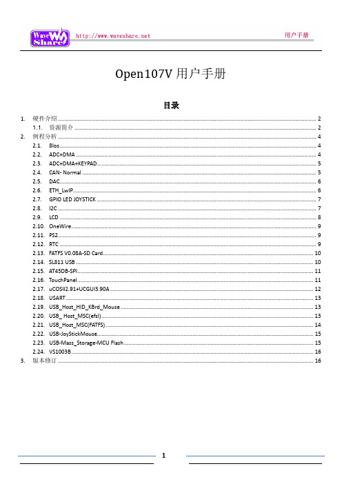
Open107V用户手册目录1. 硬件介绍 (2)1.1.资源简介 (2)2. 例程分析 (4)2.1. 8Ios (4)2.2. ADC+DMA (4)2.3. ADC+DMA+KEYPAD (5)2.4. CAN- Normal (5)2.5. DAC (6)2.6. ETH_LwIP (6)2.7. GPIO LED JOYSTICK (7)2.8. I2C (7)2.9. LCD (8)2.10. OneWire (9)2.11. PS2 (9)2.12. RTC (9)2.13. FATFS V0.08A-SD Card (10)2.14. SL811 USB (10)2.15. AT45DB-SPI (11)2.16. TouchPanel (11)2.17. uCOSII2.91+UCGUI3.90A (12)2.18. USART (13)2.19. USB_Host_HID_KBrd_Mouse (13)2.20. USB_ Host_MSC(efsl) (13)2.21. USB_Host_MSC(FATFS) (14)2.22. USB-JoyStickMouse (15)2.23. USB-Mass_Storage-MCU Flash (15)2.24. VS1003B (16)3. 版本修订 (16)1.硬件介绍1.1. 资源简介[ 芯片简介 ]1.STM32F107VCT6STM32功能强大,下面仅列出STM32F107VCT6的核心资源参数:内核:Cortex-M3 32-bit RISC;工作频率:72MHz,1.25 DMIPS/MHz;工作电压:2-3.6V;封装:LQFP100;I/O口:80;存储资源:256kB Flash,64kB RAM;接口资源:3 x SPI,3 x USART,2 x UART,2 x I2S,2 x I2C;1 x Ethernet MAC,1 x USB OTG,2 x CAN;模数转换:2 x AD(12位,1us,分时16通道),[ 其它器件简介 ]3."5V DC"或"USB"供电选择开关切换到上面,选择5V DC供电;切换到下面,选择USB供电。
ST STM3210E-SK IAR 数据手册
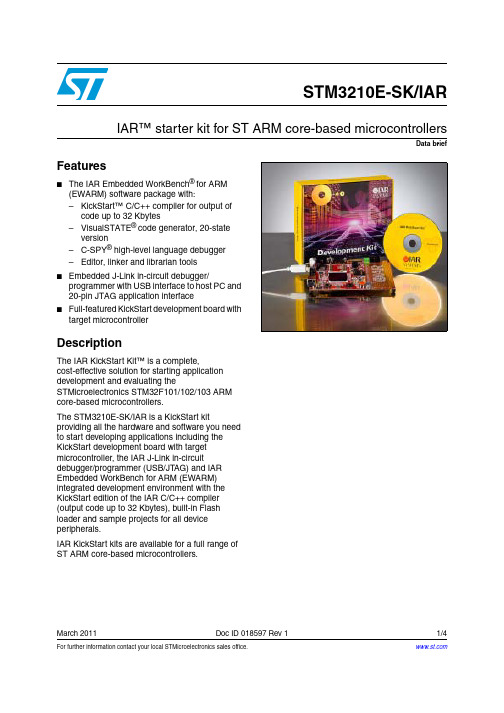
Data briefFor further information contact your local STMicroelectronics sales office.March 2011Doc ID 018597 Rev 11/4STM3210E-SK/IARIAR™ starter kit for ST ARM core-based microcontrollersFeatures■The IAR Embedded WorkBench ® for ARM(EWARM) software package with:–KickStart™ C/C++ compiler for output ofcode up to 32 Kbytes–VisualSTATE ® code generator, 20-stateversion–C-SPY ® high-level language debugger–Editor, linker and librarian tools■Embedded J-Link in-circuit debugger/ programmer with USB interface to host PC and20-pin JTAG application interface■Full-featured KickStart development board with target microcontrollerDescriptionThe IAR KickStart Kit™ is a complete,cost-effective solution for starting applicationdevelopment and evaluating theSTMicroelectronics STM32F101/102/103 ARMcore-based microcontrollers.The STM3210E-SK/IAR is a KickStart kitproviding all the hardware and software you needto start developing applications including theKickStart development board with targetmicrocontroller, the IAR J-Link in-circuitdebugger/programmer (USB/JTAG) and IAREmbedded WorkBench for ARM (EWARM)integrated development environment with theKickStart edition of the IAR C/C++ compiler(output code up to 32Kbytes), built-in Flashloader and sample projects for all deviceperipherals.IAR KickStart kits are available for a full range ofST ARM core-based microcontrollers.Starter kit architecture STM3210E-SK/IAR 2/4 Doc ID 018597 Rev 1Starter kit architectureThe IAR development software is a suite of software tools for all phases of applicationdevelopment that includes:●IAR Embedded WorkBench ® for ARM integrated development environment with theKickStart 32KB C/C++ compiler to build the application and the C-SPY™ debugger fordebugging the application while it runs on your microcontroller.●VisualSTATE ® 20-state version of IAR’s graphical design environment with C/C++code generator for developing application code based on machine states.●J-Link in-circuit debugger/programmer (USB/JT AG) which integrates fully with EWARM, allowing you to download the application to your target and debug it while itruns on your ST ARM core-based microcontroller. J-Link is embedded on the KickStartdevelopment board in the STM3210E starter kit.●KickStart development board that provides a full range of features to help developers evaluate and start developing applications for the included STM32F103ZETxmicrocontroller. The board is powered from the J-Link’s USB connection with the hostPC. The STM3210E KickStart development board key features include:–Embedded J-Link –20-pin JTAG connector –20-pin trace tool connector –SD/MMC connector –Power supply from USB connection –MEMS accelerometer –2 USART connectors –SPI –I 2C –USB connector –4 user LEDs –Graphic LCD display –Potentiometer connected to ADC –3 user, tamper, wake-up push buttons –Reset button –Wrap area –Stepper motorOrdering informationIAR KickStart kits can be ordered from IAR or from your nearest ST distributor or salesoffice for STM32 performance and access line microcontrollers with up to 512K Flash(ST order code: STM3210E-SK/IAR).For more information and complete documentation, please refer to the IAR web site or theSTMicroelectronics microcontroller support site on .STM3210E-SK/IAR Revision history Revision historyTable 1.Document revision historyDate Revision Changes15-Mar-20111Initial release.Doc ID 018597 Rev 13/4STM3210E-SK/IARPlease Read Carefully:Information in this document is provided solely in connection with ST products. STMicroelectronics NV and its subsidiaries (“ST”) reserve the right to make changes, corrections, modifications or improvements, to this document, and the products and services described herein at any time, without notice.All ST products are sold pursuant to ST’s terms and conditions of sale.Purchasers are solely responsible for the choice, selection and use of the ST products and services described herein, and ST assumes no liability whatsoever relating to the choice, selection or use of the ST products and services described herein.No license, express or implied, by estoppel or otherwise, to any intellectual property rights is granted under this document. If any part of this document refers to any third party products or services it shall not be deemed a license grant by ST for the use of such third party products or services, or any intellectual property contained therein or considered as a warranty covering the use in any manner whatsoever of such third party products or services or any intellectual property contained therein.UNLESS OTHER WISE SET FOR TH IN ST’S TER MS AND CONDITIONS OF SALE ST DISCLAIMS ANY EXPR ESS OR IMPLIED WAR R ANTY WITH R ESPECT TO THE USE AND/OR SALE OF ST PR ODUCTS INCLUDING WITHOUT LIMITATION IMPLIED WARRANTIES OF MERCHANTABILITY, FITNESS FOR A PARTICULAR PURPOSE (AND THEIR EQUIVALENTS UNDER THE LAWS OF ANY JURISDICTION), OR INFRINGEMENT OF ANY PATENT, COPYRIGHT OR OTHER INTELLECTUAL PROPERTY RIGHT. UNLESS EXPR ESSLY APPR OVED IN WR ITING BY AN AUTHOR IZED ST R EPR ESENTATIVE, ST PR ODUCTS AR E NOT RECOMMENDED, AUTHORIZED OR WARRANTED FOR USE IN MILITARY, AIR CRAFT, SPACE, LIFE SAVING, OR LIFE SUSTAINING APPLICATIONS, NOR IN PRODUCTS OR SYSTEMS WHERE FAILURE OR MALFUNCTION MAY RESULT IN PERSONAL INJURY, DEATH, OR SEVERE PROPERTY OR ENVIRONMENTAL DAMAGE. ST PRODUCTS WHICH ARE NOT SPECIFIED AS "AUTOMOTIVE GRADE" MAY ONLY BE USED IN AUTOMOTIVE APPLICATIONS AT USER’S OWN RISK.Resale of ST products with provisions different from the statements and/or technical features set forth in this document shall immediately void any warranty granted by ST for the ST product or service described herein and shall not create or extend in any manner whatsoever, any liability of ST.ST and the ST logo are trademarks or registered trademarks of ST in various countries.Information in this document supersedes and replaces all information previously supplied.The ST logo is a registered trademark of STMicroelectronics. All other names are the property of their respective owners.© 2011 STMicroelectronics - All rights reservedSTMicroelectronics group of companiesAustralia - Belgium - Brazil - Canada - China - Czech Republic - Finland - France - Germany - Hong Kong - India - Israel - Italy - Japan - Malaysia - Malta - Morocco - Philippines - Singapore - Spain - Sweden - Switzerland - United Kingdom - United States of America4/4 Doc ID 018597 Rev 1。
使用操作与维护说明书
金龙联合汽车工业(苏州)有限公司 二○一一年四月
海格客车
3906_UM0002C 中巴使用操作与维护说明书
201105 版
目录
一、整车概述........................................................................................................................ 1
海格客车豪华车使用操作与维护说明书2011053235一整车概述驾驶区海格客车豪华车使用操作与维护说明书20110542351dvd换碟机2点烟器3行车记录仪4led电子路牌5空调机械控制面板6翘板开关7媒体播放器插口8杂物盒9倒车监视器10翘板开关11麦克风控制面板12组合开关13组合仪表14方向盘15点火开关16缓速器操作手柄17翘板开关及仪表台指示灯18自动变速箱显示屏19翘板开关及仪表台指示灯20手制动21空调电子控制面板22翘板开关23司机座椅24变速箱操纵杆海格客车豪华车使用操作与维护说明书2011055235车辆外观1前雾灯2前大灯3标志4电子路牌5后视镜6侧窗玻璃7安全窗8行李舱门9燃油加注口10乘客门11乘客门泵海格客车豪华车使用操作与维护说明书2011056235车身内饰1乘客座椅2液晶显示器3乘客控制面板4停车指示灯5行李架6电子路牌7停车按钮海格客车豪华车使用操作与维护说明书2011057235发动机舱后视图1角传动器2传动带3空调压缩机4膨胀水箱5发电机6动力转向油储液罐7发动机后启动装置海格客车豪华车使用操作与维护说明书2011058235钥匙1乘客门遥控钥匙2点火开关钥匙3行李舱门钥匙4乘客门应急开关钥匙海格客车豪华车使用操作与维护说明书2011059235特殊标识说明warning警告可能对人身安全有危险的时使用
MCUB板使用说明书课案
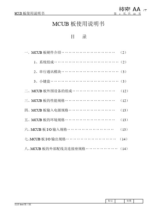
技密AA (工MCUB板使用说明书第1页, 共22页MCUB板使用说明书目录一.MCUB板硬件介绍‥‥‥‥‥‥‥‥‥‥‥‥‥‥‥(2)1、系统组成‥‥‥‥‥‥‥‥‥‥‥‥‥‥‥‥‥‥(2)2、串行通讯模块‥‥‥‥‥‥‥‥‥‥‥‥‥‥‥‥(3)3、小键盘‥‥‥‥‥‥‥‥‥‥‥‥‥‥‥‥‥‥‥(3)二、MCUB板外围设备的组成‥‥‥‥‥‥‥‥‥‥‥‥(12)三、MCUB板的性能规格‥‥‥‥‥‥‥‥‥‥‥‥‥‥(12)四、MCUB板输入电源规格‥‥‥‥‥‥‥‥‥‥‥‥‥(13)五、MCUB板的环境规格‥‥‥‥‥‥‥‥‥‥‥‥‥‥(13)六、MCUB板I/O输入规格‥‥‥‥‥‥‥‥‥‥‥‥‥(13)七、MCUB板I/O输出规格‥‥‥‥‥‥‥‥‥‥‥‥‥‥(14)八、MCUB板的外部配线及连接座规格‥‥‥‥‥‥‥‥‥(14)一、MCUB板硬件介绍1、系统组成。
微机MCUB是一块具有高集成度的微机板,集成了电梯中的变频控制,逻辑控制,串行通讯等3大功能,完全替代了GVF-Ⅲ电梯中VG7S、FMT、SCL-A这三个模块。
MCUB板由32位逻辑控制CPU、8位串行通讯CPU、16位变频核心控制和变频管理控制CPU、程序存储器、输入输出、串行通讯口、CAN控制口、PC通讯口和小键盘及数码显示等模块组成。
其外观图(图一)及各部分名称如下所示:(3)(2)(1)(29)(28)(27)(4)(5)(26)(6)(25)(7)(24)(8)3)(13)(23)(9)(22)(10)(21)(11)(20)(19)(12)(13)(14)(15)(16)(17)()图一(1)主微机68376(2)串行程序在线升级接口:CN302(3)管理DSP在线升级接口:CN4(4)功率模块插接口:CN2(5)功率模块插接口:CN1(6)同步电机编码器扩展接口:CN9(7)核心DSP在线升级接口:CN5(8)变频器操作面板键盘插口:CN3(9)RS232接口:CN12(10)异步电机旋转编码器接口:CN11(11)并联、群控和小区遥监RS485通讯接口:FR(12)板载+24V继电器:10TZ(13)板载+48V继电器:15BX(型号:MY4)(14)板载+48V继电器:50B(型号:MY4)(15)运行接触器驱动端子:Z10(16)抱闸接触器驱动端子:Z15B(17)板载+48V继电器:40D (型号:MY4)(18)板载+48V继电器:100R(型号:MY4)(19)板载+24V继电器:Z100R(20)+48V信号输出接口:FE(21)+24V信号输出接口:FD(22)上行强迫减速开关输入接口:SDSU(23)下行强迫减速开关输入接口:SDSD(24)+48V信号输入接口:FC(25)+48V信号输入接口:FB(26)+48V信号输入接口:FA(27)串行通讯接口:SCL(28)小键盘(3键)(29)七段LED显示(3位)2、通讯模块。
希斯特电动货车S1.0E和S1.2E系列技术指南说明书

S1.0 E, S1.2 E SERIES TECHNICAL GUIDES1.0 E, S1.2 E1-11-21-3NOTE:Specifications are affected by the condition of the vehicle and how it is equipped, as well as the nature and condition of the operating area. Inform your dealer of the nature and condition of the intended operating area when purchasing your Hyster T ruck.(1)These values may vary of +/-5%.(2)A vailable batteries 24V / 150Ah (144 kg) ; 24V / 200Ah Polypropylene case version (160 kg) ; 24V / 150Ah Polypropylenecase version (125 kg)(3)Available batteries 24V / 200Ah Polypropylene case version (160 kg)(4)W ith 2 stg mast and b5=570mm the s dimension increases 5mm for first 250mm at toe(5)These values are with loadbackrest up(6)These values are with loadbackrest down(7)Available battery 24V / 100Ah Li-Ion (144 kg)(8)Available battery 24V / 200Ah Li-Ion (154 kg)MAST TABLES(1)With free lift of 100 mm.(2)All weights are: mast structures (weldment, cylinders, chain, pulley) + oil. EXCLUDED: forks, accessories(3)With optional load backrest value is increased of 585mm Specification data is based on VDI 2198 NOTICECare must be exercised when handling elevated loads. When the carriage and/ or load is elevated, truck stability is reduced. It is important that the mast tilt in either direction is kept to a minimum when loads are elevated. Operators must be trained and must read, understand and follow the instructions contained in the Operating Manual. All values are nominal values and they are subject to tolerances. For further information, please contact the manufacturer. Hyster products are subject to change without notice. Lift trucks illustrated may feature optional equipment. Values may vary with alternative configurations.Safety: This truck conforms to thecurrent EU requirements.3Lift Height (1) h 3 (mm)Height, mast loweredh 1 (mm)Height, mast extended (3)h 4 (mm)Weight (2) (kg)S 1.0 E S 1.2 E144019001945120164021002145127184023002345135204025002545142Lift height h 3 (mm)Free lift h 2 (mm) Height, mast lowered (1)h 1 (mm)Height, mast extended (3)(mm)Weight (2)(kg) S 1.2 ES 1.0 E238010017502890188258010018503090196278010019503290203298010020503490210318010021503690218338010022503890225358010023504090233378010024504290239398010025504490256418010026504690263www.hyster.eu*********************/HysterEurope@HysterEurope/HysterEuropeSTRONG PARTNERS. TOUGH TRUCKS.TMFOR DEMANDING OPERATIONS, EVERYWHERE.Hyster supplies a complete range of warehouse equipment, IC and electric counterbalanced trucks, container handlers and reach stackers. Hyster is committed to being much more than a lift truck supplier.Our aim is to offer a complete partnership capable ofresponding to the full spectrum of material handling issues: Whether you need professional consultancy on your fleet management, fully qualified service support, or reliable parts supply, you can depend on Hyster.Our network of highly trained dealers provides expert, responsive local support. They can offer cost-effective finance packages and introduce effectively managedmaintenance programmes to ensure that you get the best possible value. Our business is dealing with your material handling needs so you can focus on the success of your business today and in the future.HYSTER-YALE UK LIMITED trading as Hyster Europe. Registered Address: Centennial House, Building 4.5, Frimley Business Park, Frimley, Surrey GU16 7SG, United Kingdom.Registered in England and Wales. Company Registration Number: 02636775.©2020 HYSTER-YALE UK LIMITED, all rights reserved. HYSTER, , and STRONG PARTNERS. TOUGH TRUCKS. are trademarks of HYSTER-YALE Group, Inc.NDIIThane is a trademarks of Wicke GmbH + Co. KG.Hyster products are subject to change without notice. Forklift trucks illustrated may feature optional equipment.Printed in EU. Part number: 3990177 Rev. 08-04/20-TLCHYSTER EUROPECentennial House, Frimley Business Park, Frimley, Surrey, GU16 7SG, England.Tel: +44 (0) 1276 538500。
布谷森集成火警系统远程维护手册说明书

Integrated Fire Alarm Systems from BoschRemote Services Handbook21 ABOUT REMOTE SERVICESConnecting to the future 3 The Remote Portal 4The Remote Services Package52 B ENEFITS FOR YOUR DAILY WORKSupporting technicians in the field 6Troubleshooting and support with FSP-5000-RPS7Flexible user management 8 - 9 Operation and real-time awareness Up-to-date system status 10 Service and connection history 10 Maintenance and ServiceEffective service preparation 11 Efficient on-site visits 12Automatic documentation with Remote Maintenance133 MANAGING LICENSES 14 - 15ContentConnecting to the Future1 About Remote ServicesRemote ConnectUse your PC andFSP-5000-RPS toconnect andmaintain a systemRemoteMaintenanceOptimize supportduring and after yourwalk tests on your PC,tablet and phoneWhen you’re managing different security and safetysystems across many locations, technology can beyour greatest asset. Bosch helps to provide your cus-tomers with immaculate remote support and enhancedperformance while optimizing your day-to-day opera-tions. Bosch Remote Services for fire alarm systemscombines all these benefits in one cutting-edge andsecure solution which scales with your business.All Services are managed through the Bosch RemotePortal. It can be used with any browser interface onceyou are registered and a system is connected to it.The connection is encrypted and secured by the SecureNetwork Gateway and Bosch Security Servers.How to manage your fire alarm systems and how thisdirectly benefits the daily comissioning, operationsas well as maintenance work for fire alarm systems isexplained in the following chapters.31 | About Remote Services Remote PortalHow to registerThe Remote Portal can be accessed on the following Link: When first accessing the portal please register an account for your company, which will then function as an administrator account. Every new fire alarm system will connect to this account and its Remote ID. Each particular company account has a unique Remote ID assigned. This Remote ID is required when connecting a fire alarm system to the Remote Portal. System HierarchyAfter a successful login, the system overview on the starting menu, shows all connected fire alarm systems. The names of the systems result from the name as set-up in the configuration of the fire alarm system. All systems can be arranged in freely definable groups that contain multiple systems. This helps you to keep an overview on regions, customers or support groups. Additional groups can be added by clicking on the plus button in the right-bottom corner of the system over-view (see figure above).There is no limit to the depth of the nesting or combi-nation of elements at any level. The Remote Portal dis-plays the hierarchy as a tree structure (granting access to the whole hierarchy, shown on the left-hand side of the screen) and by displaying the system and group cards of the current level on the right hand side of the screen. Use the tree to navigate to any group or level of the hierarchy and cards to drill down in the hierarchy from current level.45Remote Services PackageRemote Services help to efficiently monitor, maintain and service the individual fire detection equipment, ensuring highest safety standards. In the following section you find a brief overview of the three innovative features provided in the package.1 | About Remote ServicesCity sitesOpera House, MunichRemote ConnectRemote AlertA remote internet connection that enhances your operations. Secure remote connection for:• Configuration • Service• TroubleshootingEasy setup within 30 minutes.Optimized for seamless integra-tion into RPS.Customized alerts, sent to you and your customers for additional peace of mind.Faults and alarms are automat-ically transmitted to mobile devices via SMS and E-Mail.Easy user management: define responsibilities for specific people as needed.RemoteMaintenanceMaintain your system efficiently with the integrated tool that monitors the condition of every installed device.Access live fire system data.Prepare detailed maintenance documentation while testing with a tablet-optimized interface. Stay connected with the panel while maintaining the system.Receive easy-to-understand fire system data.Service history is stored within the Remote Services Portal.Efficiency increase of at least 25%:Via simultaneous maintenance and detailed reporting.Intended end customer gets infor-mation, enabling more effective maintenance of your system.6Remote Connect from Bosch delivers unparalleled connectivity with little to no IT expertise required. Enjoy the advantages of an entirely remote configura-tion, not just a remote display. Avail yourself of the 24/7 access and availability, thus even global monitoring is no challenge anymore. Enabling a prompt reaction time significantly augments your customer satisfaction. Your assets will always be safe and protected, thanks to Remote Connect.Supporting Technicians in the Field2 Benefits for your daily workFurther benefits include the possibilities of preventive maintenance and the monitoring of detectors. As a result maintenance and travelling costs will be reduced due to shorter system downtime.7When you have successfully connected a system to the Remote Portal, you can use Remote Connect .Remote Connect allows you to connect to a fire alarm system using the Secure Network Gateway from Bosch with very few steps necessary. The configuration software FSP-5000-RPS connects to the systems as if you were on-site. If allowed by local regulations, you then may modify configuration, remotely control the system via the Remote Terminal as well as update or troubleshoot anytime and from anywhere you need to.Especially demanding applications require a lot of atten-tion during the initial set-up and commissioning phase – But oftentimes configuration experts are needed to fine-tune the system: With Remote Connect experts can now support technicians in the field remotely from their office, once an issue occurs.Troubleshooting and Support with FSP-5000-RPS2 | Benefits for your daily work - Supporting technicians in the fieldWell trained configuration experts can quickly modify necessary details and guide the local technicians as if they were themselves on-site. This way your company optimizes both costs due to a much more efficient allo-cation of staff, but also the top-line of business by pro-viding better commissioning and faster reaction times. Ultimately this creates more business opportunities for you, allowing your teams expertise to scale to its full potential.8The Remote Portal allows you to manage your systems according the way you run your business. With a highly adaptive user management you can differentiate three user levels: administrator, technician and customer. Each of them have their distinctive set of privileges on the Remote Portal and via FSP-5000-RPS.2 | Benefits for your daily work - Supporting technicians in the fieldFlexible User ManagementAdministratorTechnican AAs an Admin you can create andmanage different projects.Factory DresdenCompany CologneOpera MunichCustomer AUse RemoteMaintenance for Walktests and Sensor ReportsCan receive alerts about TroublesCan receive alerts via e-Mail or SMS when fire isdetectedTechnician A Technician A,Customer ATechnician C Customer CTechnician B Technician B, ACustomer BBy default any system within the Remote Portal is not accessible by technicians or mobile users until access is granted explicitly. Administrators always have access to all systems connected to their Remote ID. The details of these access rights are explained hereafter.92 | Benefits for your daily work - supporting technicians in the fieldAdding a technician to a group grants access to all systems of this group and the systems of any nested group. Access rights accumulate from top to bottom of the hierarchy, as explained in the following example which is illustrated in the box on the right side.Technician access can be granted either for a particular system or for a set of systems by adding a technician to a system or group respectively. Technicians access allows to view the particular systems in the Remote Portal via a browser and additionally enables access to the system via the client software such as FSP-500-RPS. For further details on granting access and permis-sion, please refer to the user section of this document.Removing AccessRemoving access is only feasible on the highest entrylevel. Based on the example, the access for Technician A can only be removed on the highest entry level of Group 1, 1-1. If access is removed at a lower level such as 2-1, removal is denied. Removal of access, when applicable, is shown via a red …-“ sign in the bottom right corner of the menu.Status AggregationCoordinating and establishing systems in a group hier-archy, results in the aggregation of status information of all the systems within a group. Each group always displays the aggregate status of all systems (in par-ticular systems functionality, connectivity and service status), with failure status appearing in the top group, displayed by the status icons. This provides a quick way to verify functionality of a large number of devices contained in a group. Further, this enables simplified navigation in case of occurring errors.Granting AccessGroup 1 - Technician A, B System 1-1 System 1-2Group 2 - Technician C System 2-1 System 2-2 - Technician DFor this example technicians A and B can access systems 1-1, 1-2, 2-1 and 2-2, whereas technician C can only access system 2-1 and 2-2 and technician D only system 2-2. Resulting access rights are shown at every level, as an example, in system 2-2 all technicians are granted access, matching the configuration shown in the example above.10Once a system is commissioned and running at the customer‘s site, you want to make sure that you are up-to-date on its performance. Remote Alert is the feature of Bosch Remote Services that guaran-tees to keep you in the loop should anything happen.In case of any event, service or alarm all subcribers will be notified, in other words, all defined recipi-ents, are immeadiately notified via E-mail or SM S. Should multiple triggering events of one specific type occur, only the initial ten events within a 24h period will be sent, reducing the number of messages in case of larger event bursts.Furthermore the Remote Portal limits total amount of SMS to 50 per day, per account. The portal alert his-tory however always shows all events, independent of whether a message was sent or not.You can decide who will be informed in case of an alarm or system troubles. Depending on your settings they will get an SMS or E-Mail notification.The following overview shows the different types of event and notification channels. SM S notifications include only a short information text of the type of event, the site and and its location, while the E-mail feature offers additional more detailed reports.Up-To-Date System StatusService and Connection HistoryWhen you select a system in the system overview on the Remote Portal, you can also get insights into the alarm and service history.Via the walktest feature within the service history you can get an overview when the last service visit was conducted. It also allows to monitor how many points were checked at a certain time as well as to check specific reports of the system and the detector.3 Operation and Real-Time Awareness113 | Operation and real-time awarenessShows if the detector is in revision mode.Effective Service PreparationIn the service industry every minute counts. Therefore, Remote Maintenance offers you live system data down to an LSN element of the complete fire alarm system. You can find this data here for each LSN loop:Using a periodical polling of the elements connected to the fire alarm system, you can get an overview on the sensor data of detectors on the LSN bus. This allows you to preemptively know the pollution state of each individual detector. There is no more uncertainty what to expect before you reach the customer site.You only need to take the specific new detectors to the customer in need for replacement. On site you can immediately start the work on critical elements, ensur-ing your customer’s business continuity. The data help-ing you to prepare the specific service visit, is illus-trated below according to the automatic fire detector range from Bosch.123 | Operation and real-time awarenessEfficient on-site VisitsWhen you are on-site to do maintenance not only every minute counts, but also you want to minimize the inter-ruption to your customer’s business. The integrated walk test feature of Remote Maintenance helps you to be faster when testing detectors. With the click of a button you start the walk test on any device with a web browser and all detectors in revision mode appear ready for the automated testing. When you introduce test gas for triggering, an optical detector will automat-ically show itself as “tested” – This way you do not need to monitor the panel display for successful triggering and the Remote Portal will handle the documentation for you.If there is a fire alarm on another loop of the system, the Remote Portal will show a pop-up warning message – depending on local regulations this feature helps you to reduce the necessary manpower for the walk testfrom two to just one technician on site.133 | Operation and real-time awarenessRepeat until alldetectors were tested…Start walktest“Use your mobile device to make use of the Remote Portal during the walktest. Select the System and Panel where you are going to test and click: …Start walktest“.Test the detectors as usualTest the detectors in the building with your usualequipment.3Get feedback from the Remote Portal everytime a detector wastested successfullyThe Remote Portal offers visual and acoustic feedback to prove immedeately if a detector was successfully tested.4Download the ReportAfter every walktest you can download a detailed Report from the Remote Portal.5Stop the walktest after testing all detectorsIf you want to continue the walktest the next day, just close the Remote Portal. To end the whole walktest, klick …Stop Walktest“.6Put the detectors you want to test in revision mode on the panel1Automatic Documentation with Remote Maintenance14Note: The Remote Portal intelligently parses licenses information from the information entered in the dialog, it is not necessary to apply special formatting or remove extra text. Multiple license codes can be added at once. Licenses added are saved in the Remote Portal for use, but only consumed when the corresponding is activated(manually or via auto-renewal). This allows having a stock of licenses in the Remote Portal for immediate use, without inactive licenses expiring inadvertently.Dear customer,please follow the steps below to add your recently purchased licenses to your account:1. Log into your account at https://2. Click the …Licenses“ tab in the top bar.3. Click the …Add Licenses“ button.4. Copy and paste the entire license information between the dashed lines to the browser dialog box and click …Add“.----- license information (begin) -----Fire panel remote services bundle:1234: 1111-2222-3333-44441235: 2222-3333-4444-55551236: 3333-4444-5555-6666----- license information (end) -----Thank you for using Remote Services.Regards,Bosch Security Systems154 | LicensingUsing Licenses and Activating ServicesSubscribing to a service for a system will start a check for available licenses. A suitable license in the Remote Portal account will be used up and subscribed to the fire alarm system for which the service is activated. Licenses are assigned from available stock - A particu-lar license‘s assignment can be checked from the infor-mation shown on the license in the Remote Portal. The remaining life-time of a license assigned to a ser-vice is shown in the service section of a device. Once the license expires the service is no longer available and requires an extension. License expiration is high-lighted in red in a device‘s service section and the sys-tems overview screen at the services icon.Auto-RenewalFor convenience and to avoid service interruptions, services can be configured for auto-renewal upon expiry. This can be done at time of service subscription or the service settings screen for a particular service: Auto-renewal requires a license to be available when renewal is due, otherwise renewal fails. Use the license management to plan and coordinate your particularlicenses in regular intervals.Managing Licenses - Future License UsageThe licenses tab provides the necessary information and actions to manage licenses. At the top of the screen current and predicted license usage is displayed, bro-ken down by service /license type:Based on the number of devices subscribed, the remaining life-time of the subscription and auto- renewal of service subscriptions, the Remote Portal predicts when additional service licenses are needed, marking the estimated demand of licenses in red. Note that this estimation will change when additional devices are subscribed to a service.Individual License Status and MaintenenceIndividual licenses are shown below the license usage section of the screen and provide information on each purchased license, the license status (avail-able, assigned and expired) as well as its validity and assigned system.Licenses that have not yet been assigned to a system (are in available state) can be removed from an account by clicking the trashcan symbol of the license. This allows you to transfer licenses to another account or to make licenses unavailable for use.License deletion is immediate and permanent. You must copy and save the license key presented in the warning dialogue in order to reuse at a later stage.Bosch Sicherheitssysteme GmbH Robert-Bosch-Ring 585630 GrasbrunnGermany。
T_BOX车辆调度系统(B_S版)使用手册_201020907

点击
,根据用户需求在地图上选择要放大的地方进行框选。
� 自定义设置
点击
,用户可以根据个人的需要来设置车辆图标和报警声音。
数据设置是设置的串口号。
第 9 页 共 17 页
T_BOX 车辆调度
设置底部数据的信息的显示属性,用户可以根据个人的需求来选择。
第 10 页 共 17 页
T_BOX 车辆调度
4.车辆类别图标说明
注意: (在分屏 4: 3/3 ,3 为群组上的终端数,在线终端为 3)
第 14 页 共 17 页
第 7 页 共 17 页
T_BOX 车辆调度
图 5.3.1
可以根据需要修改开始与结束的时间,然后点击查询,查询完毕之后点击播放,即可显示终端在该段时 间内的行驶轨迹,地图显示如图:
显示在这个一个时段的终端行走数据的回放的具体信息
图 5.3.2. 第 8 页 共 17 页
T_BOX 车辆调度
� 框选放大
� 终端类型说明
: 调度用户
� 终端在线状态说明
:在线
:离线
� 地图状态说明(根据颜色区分)
:在线
: 初始化
:被临时群组选定
: 离线
第 11 页 共 17 页
T_BOX 车辆调度
二、功能介绍
1.终端信息
可以对所选的车辆的相应信息进行查看需修改。单击选中车辆,点击鼠标右键,选择 “查看当前车辆信 息”可以查看当前车辆的“终端编号” 、 “终端名称” 、 “群组编号”等车辆相应信息;选中“修改车辆信息” , 可对车辆的“车辆号码” 、 “群组编号”等信息进行修改。
还原鼠标............................................................................................................................................... 16 设置为默认视野................................................................................................................................... 16 回到默认视野处................................................................................................................................... 16
高德威产品手册(解决方案)V0.2

产品手册PRODUCT CA TALOGV1.0 ,2009/11产品手册目录CONTENTS1.GW-PR-9902T汽车牌照识别器 (5)1.1 产品简介 (5)1.2 权威检测 (5)1.3 产品特点 (5)1.4 主要功能 (5)1.5 应用领域 (6)1.6 解决方案 (6)1.6.1标清独立处理单元车牌识别方案 (7)1.6.1.1 主要特性 (8)1.6.1.2 订货型号 (8)1.6.1.3 硬件接口 (8)1.6.1.4 技术参数 (8)1.6.1.5 应用场合 (9)1.6.1.6 应用举例-高速公路收费系统 (9)1.6.1.6.1 方案特点 (9)1.6.1.6.2 系统框图 (10)1.6.1.6.3 设备清单 (10)1.6.2标清板卡处理单元车牌识别方案 (11)1.6.2.1 主要特性 (11)1.6.2.2 订货型号 (11)1.6.2.3 硬件接口 (11)1.6.2.4 技术参数 (11)1.6.2.5 应用场合 (12)1.6.2.6 应用举例-高速公路收费系统 (12)1.6.2.6.1 方案特点 (12)1.6.2.6.2 系统框图 (13)1.6.2.6.3 设备清单 (13)1.6.3标清独立处理单元LED补光车牌识别方案 (14)1.6.3.1 主要特性 (14)1.6.3.2 订货型号 (14)1.6.3.3 硬件接口 (14)1.6.3.4 技术参数 (14)1.6.3.5 应用场合 (15)1.6.3.6 应用举例-高速公路收费系统 (16)1.6.3.6.1 方案特点 (16)1.6.3.6.2 系统框图 (16)1.6.3.6.3 设备清单 (16)1.6.4标清板卡处理单元LED补光车牌识别方案 (17)1.6.4.1 主要特性 (17)1.6.4.2 订货型号 (17)1.6.4.3 硬件接口 (17)1.6.4.4 技术参数 (18)1.6.4.5 应用场合 (19)1.6.4.6 应用举例-高速公路收费系统 (19)1.6.4.6.1 方案特点 (19)1.6.4.6.2 系统框图 (20)1.6.4.6.3 设备清单 (20)1.6.5标清独立处理单元双摄像头车牌识别方案 (20)1.6.5.1 主要特性 (21)1.6.5.2 订货型号 (21)1.6.5.3 硬件接口 (21)1.6.5.4 技术参数 (21)1.6.5.5 应用场合 (22)1.6.5.6 应用举例-高速公路收费系统 (23)1.6.5.6.1 方案特点 (23)1.6.5.6.2 系统框图 (24)1.6.5.6.3 设备清单 (24)1.6.6标清板卡处理单元双摄像头车牌识别方案 (25)1.6.6.1 主要特性 (25)1.6.6.2 订货型号 (25)1.6.6.3 硬件接口 (25)1.6.6.4 技术参数 (25)1.6.6.5 应用场合 (26)1.6.6.6 应用举例-高速公路收费系统 (26)1.6.6.6.1 方案特点 (26)1.6.6.6.2 系统框图 (27)1.6.6.6.3 设备清单 (27)1.6.7高清车牌识别方案 (28)1.6.7.1 主要特性 (28)1.6.7.2 订货型号 (28)1.6.7.3 硬件接口 (28)1.6.7.4 技术参数 (29)1.6.7.5 应用场合 (30)1.6.7.6 应用举例-高速公路收费系统 (30)1.6.7.6.1 方案特点 (30)1.6.7.6.2 系统框图 (31)1.6.7.6.3 设备清单 (31)1.6.8高清LED补光车牌识别方案 (32)1.6.8.1 主要特性 (32)1.6.8.2 订货型号 (32)1.6.8.3 硬件接口 (32)1.6.8.4 技术参数 (33)1.6.8.5 应用场合 (34)1.6.8.6 应用举例-高速公路收费系统 (34)1.6.8.6.1 方案特点 (34)1.6.8.6.2 系统框图 (35)1.6.8.6.3 设备清单 (35)1.6.9 高清含终端服务器车牌识别方案 (36)1.6.9.1 主要特性 (36)1.6.9.2 订货型号 (36)1.6.9.3 硬件接口 (37)1.6.9.4 技术参数 (37)1.6.9.5 应用场合 (39)1.6.9.6 应用举例-治安查报站系统 (39)1.6.9.6.1 方案特点 (39)1.6.9.6.2 系统框图 (40)1.6.9.6.3 设备清单 (40)1.6.10高清含终端服务器LED补光车牌识别方案 (41)1.6.10.1 主要特性 (41)1.6.10.2 订货型号 (42)1.6.10.3 硬件接口 (42)1.6.10.4 技术参数 (42)1.6.10.5 应用场合 (44)1.6.10.6 应用举例-治安查报站系统 (44)1.6.10.6.1 方案特点 (44)1.6.10.6.2 系统框图 (45)1.6.10.6.3 设备清单 (45)2. GDW-VM-2003车辆智能监测记录系统 (46)2.1 产品简介 (46)2.2 权威检测 (46)2.3 产品特点 (47)2.4 设备功能 (47)2.5 应用领域 (47)2.6 解决方案 (48)2.6.1标清卡口方案 (49)2.6.1.1 主要特性 (49)2.6.1.2 订货型号 (49)2.6.1.3 硬件接口 (49)2.6.1.4 技术参数 (49)2.6.1.5 应用场合 (50)2.6.1.6 应用举例-治安卡口系统 (51)2.6.1.6.1 方案特点 (51)2.6.1.6.2 系统框图 (51)2.6.1.6.3 设备清单 (51)2.6.2标清硬盘录像一体卡口方案(预告) (56)2.6.2.1 主要特性 (56)2.6.2.2 订货型号 (56)2.6.2.3 硬件接口 (56)2.6.2.4 技术参数 (56)2.6.2.5 应用场合 (57)2.6.3高清卡口SIC1G方案 (58)2.6.3.1 主要特性 (58)2.6.3.2 订货型号 (58)2.6.3.3 硬件接口 (59)2.6.3.4 技术参数 (59)2.6.3.5 应用场合 (61)2.6.3.6 应用举例-治安卡口系统 (61)2.6.3.6.1 方案特点 (61)2.6.3.6.2 系统框图 (62)2.6.3.6.3 设备清单 (62)2.6.4高清LED补光卡口方案 (63)2.6.4.1 主要特性 (63)2.6.4.2 订货型号 (64)2.6.4.3 硬件接口 (64)2.6.4.4 技术参数 (64)2.6.4.5 应用场合 (66)2.6.4.6 应用举例-治安卡口系统 (67)2.6.4.6.1 方案特点 (67)2.6.4.6.2 系统框图 (68)2.6.4.6.3 设备清单 (68)2.6.5高清卡口(不含终端服务器)方案 (69)2.6.5.1 主要特性 (69)2.6.5.2 订货型号 (69)2.6.5.3 硬件接口 (70)2.6.5.4 技术参数 (70)2.6.5.5 应用场合 (71)2.6.5.6 应用举例-ETC收费系统 (72)2.6.5.6.1 方案特点 (72)2.6.5.6.2 系统框图 (73)2.6.5.6.3 设备清单 (73)2.6.6高清LED补光卡口(不含终端服务器)方案 (74)2.6.6.1 主要特性 (74)2.6.6.2 订货型号 (74)2.6.6.3 硬件接口 (74)2.6.6.4 技术参数 (75)2.6.6.5 应用场合 (76)2.6.6.6 应用举例-超速预警提醒系统 (77)2.6.6.6.1 方案特点 (77)2.6.6.6.2 系统框图 (78)2.6.6.6.3 设备清单 (78)高德威产品手册1.GW-PR-9902T汽车牌照识别器1.1 产品简介GW-PR-9902T汽车牌照识别器系列产品,采用先进的数字图像处理和模式识别技术,基于嵌入式的硬件处理平台和包含智能补光技术的专用成像系统,可实现车辆牌照的自动识别及图像抓拍。
赣州芯讯电子科技有限公司MEMS可燃气传感器说明书
MEMS Combustible Gas Sensor(Model No.:GM-402B)ManualVersion: 1.1Valid from: 2017-05-10Zhengzhou Winsen Electronics Technology Co., LtdStatementThis manual copyright belongs to Zhengzhou Winsen Electronics Technology Co., LTD. Without the written permission, any part of this manual shall not be copied, translated, stored in database or retrieval system, also can’t spread through electronic, copying, record ways.Thanks for purchasing our product. In order to let customers use it better and reduce the faults caused by misuse, please read the manual carefully and operate it correctly in accordance with the instructions. If users disobey the terms or remove, disassemble, change the components inside of the sensor, we shall not be responsible for the loss.The specific such as color, appearance, sizes &etc, please in kind prevail.We are devoting ourselves to products development and technical innovation, so we reserve the right to improve the products without notice. Please confirm it is the valid version before using this manual. At the same time, users’ comments on optimized using way are welcome.Please keep the manual properly, in order to get help if you have questions during the usage in the future.Zhengzhou Winsen Electronics Technology CO., LTDGM-402B MEMS Combustible Gas SensorProduct descriptionMEMS combustible gas sensor is using MEMSmicro-fabrication hot plate on a Si substrate base,gas-sensitive materials used in the clean air with lowconductivity metal oxide semiconductor material. When thesensor exposed to gas atmosphere, the conductivity ischanging as the detected gas concentration in the air. Thehigher the concentration of the gas, the higher theconductivity. Use simple circuit can convert the change ofconductivity of the gas concentration corresponding to theoutput signal.CharacterMEMS technology, Strong constructionHigh sensitivity to combustible gasesSmall sizes and low power consumptionFast response and resumeSimple drive circuit, Long lifespanApplicationGas leak detection for mobile phones, computers and other consumer electronics applications; also apply for home, commercial use of the combustible gas leakage monitoring devices, gas leak detectors, fire / security detection system.Parameters Stable1.Part No. GM-402BSensor Type MEMSStandard Encapsulation CeramicDetection Gas CH4, C3H8 &etc.Detection Range 1~10000ppm (C3H8)Standard Circuit ConditionsLoop Voltage V C≤24V DC Heater Voltage V H 2.8V±0.1V AC or DC Load Resistance R L AdjustableSensor character under standard testconditionsHeater Resistance R H 80Ω±20Ω(room temperature)Heater consumption P H ≤80mW sensitive materials resistance R S1KΩ~30KΩ(in 5000ppm CH4) Sensitivity S R0(in air)/Rs(in 5000ppmCH4)≥2 Concentration Slope α≤0.9(R5000ppm/R1000ppmCH4)Standard test conditionsTemp. Humidity 20℃±2℃;55%±5%RH Standard test circuit V H:2.8V±0.1V;V C :5.0V±0.1VSensor Structure DiagramPins Connection①R H1②③R H2④⑤R S1⑥⑦R S2⑧Fig1.Sensor structureBasic Circuit①Heating 1⑦Measure 1③Heating 2⑤Measure 2Fig2. GM-402B test circuitInstructions: The above fig is the basic test circuit of GM-402B.The sensor requires two voltage inputs: heater voltage (V H) and circuit voltage (V C). V H is used to supply specific working temperature to the sensor and it can adopt DC or AC power. V out is the voltage of load resistance R L which is in series with sensor. Vc supplies thedetect voltage to load resistance R L and it should adopt DC power.Sensor ’s Characteristics:Fig3.Typical Sensitivity Curve Rs means resistance in target gas with different concentration, R 0 means resistance of sensor in clean air. All tests are finished under standard test conditions. Fig4.Typical temperature/humidity characteristicsRs means resistance of sensor in 5000ppm methane (CH 4) under different temp. and humidity. Rso means resistance of the sensor in 5000ppm methane under 20℃/55%RH.Fig6. Linearity characterThe output in above Fig is the voltage of RL which is in series with sensor. All tests are finished under standard test conditions.Fig5.Responce and ResumeThe output in above Fig is the voltage of RL which is in series with sensor. All tests are finished under standard test conditions and the test gas is 5000ppm CH4.airgas concentration(ppm)Temperature(℃)Voltage output(V)gas concentration(ppm)Time(s)Long-term stability:Voltage output(V)Preheating time(days)Fig7.long-term StabilityTest is finished in standard test conditions, the abscissa is observing time and the ordinate is voltage output of RL. Instructions:1. Preheating timeSensor’s resistance may drift reversibly after long-term storage without power. It need to preheat the sensor to reach inside chemical equilibrium. Preheating voltage is same with heating voltage V H. The suggested preheating time as follow:Storage Time Suggested aging timeLess than one month No less than 48 hours1 ~ 6 months No less than 72 hoursMore than six months No less than 168 hours2. CalibrationSensor’s accuracy is effected by many factors such as reference resistance’s difference, the sensitivity difference, temperature, humidity, interfering gases, preheating time, the relationship between input and output is not linear,hysteretic and non-repetitive. For absolute concentration measurement, they need regular calibration (one-point calibration / multi-points calibration for full scale) to ensure that the measuring value is accurate. For relative measurement calibration is not required.Cautions1 .Following conditions must be prohibited1.1 Exposed to organic silicon steamSensing material will lose sensitivity and never recover if the sensor absorbs organic silicon steam. Sensors must be avoid exposing to silicon bond, fixature, silicon latex, putty or plastic contain silicon environment. 1.2 High Corrosive gasIf the sensors are exposed to high concentration corrosive gas (such as H2S, SOX, Cl2, HCL etc.), it will notonly result in corrosion of sensors structure, also it cause sincere sensitivity attenuation.1.3 Alkali, Alkali metals salt, halogen pollutionThe sensors performance will be changed badly if sensors be sprayed polluted by alkali metals salt especially brine, or be exposed to halogen such as fluorine.1.4 Touch waterSensitivity of the sensors will be reduced when spattered or dipped in water.1.5 FreezingDo avoid icing on sensor’s surface, otherwise sensing material will be broken and lost sensitivity.1.6 Applied voltageApplied voltage on sensor should not be higher than 120mW, it will cause irreversible heater damaged, also hurt from static, so anti-static precautions should be taken when touching sensors.2 .Following conditions must be avoided2.1 Water CondensationIndoor conditions, slight water condensation will influence sensors’ performance lightly. However, if water condensation on sensors surface and keep a certain period, sensors’ sensitive will be decreased.2.2 Used in high gas concentrationNo matter the sensor is electrified or not, if it is placed in high gas concentration for long time, sensors characteristic will be affected. If lighter gas sprays the sensor, it will cause extremely damage.2.3 Long time exposed to extreme environmentNo matter the sensors electrified or not, if exposed to adverse environment for long time, such as high humidity, high temperature, or high pollution etc., it will influence the sensors’ performance badly.2.4 VibrationContinual vibration will result in sensors down-lead response then break. In transportation or assembling line, pneumatic screwdriver/ultrasonic welding machine can lead this vibration.2.5 ConcussionIf sensors meet strong concussion, it may lead its lead wire disconnected.2.6 SolderingSoldering flux: Rosin soldering flux contains least chlorine and safeguard procedures.If disobey the above using terms, sensors sensitivity will be reduced.Zhengzhou Winsen Electronics TechnologyCo., LtdAdd: No.299, Jinsuo Road, National Hi-TechZone, Zhengzhou 450001 ChinaTel: +86-371-67169097/67169670Fax: +86-371-60932988E-mail:*******************Website: 。
2022年福特Edge ST配置指南说明书

Maximum towing capabilities are for properly equipped vehicles with required equipment and a 150-lb. driver and passenger and vary based on cargo, vehicle configuration, accessories, option content and number of passengers. See label on door jamb for carrying capacity of a specific vehicle. For additional information, see your Ford Dealer.Edge ST in Ford Performance Blue2022 FORD EDGEFrontal Area is the total area in square feet that a moving vehicle and trailer exposes to air resistance. The chart above shows the limitations that must be considered in selecting a vehicle/trailer combination. Exceeding these limitations may significantly reduce the performance of your towing vehicle.FRONTAL AREA CONSIDERATIONSTrailer Frontal Areaaccessory. 2. Requires Class II Trailer Tow Package (53G). 3. Edge ST. Includes Class II Trailer Tow Package (53G) standard.Notes: • C ertain states require electric trailer brakes for trailers over a specified weight. Be sure to checkstate regulations for this specified weight. WARNING: Do not tow a trailer fitted with electric trailer brakes unless your vehicle is fitted with a compatible aftermarket electronic trailer brake controller. Failure to follow this instruction could result in the loss of control of your vehicle,personal injury or death. For additional information and assistance, we recommend that you contact an authorized dealer.• Edge calculated with SAE J2807® method.• Combined weight of vehicle and trailer cannot exceed listed GCWR. • Do not exceed the Maximum Loaded Trailer Weight listed.TRAILER TOWING SELECTORREQUIRED EQUIPMENTIncludes items that must be installed.* Your New VehicleLimited Warranty (see your dealer for a copy) may be voided if you tow without them.For trailers over 1,500 pounds – Class II Trailer Tow Package (53G) and AWD*Check with your dealer for additional requirements, restrictions and limited warranty details.Edge 4Standard on ST. AVAILABLE TRAILER TOWING PACKAGENote: C ontent may vary depending on model, trim and/or powertrain. Seeyour Ford Dealer for specific content information for all light trucks that will be used for towing to help ensure easy, proper connection of trailer lights.Included with Class II Trailer Tow Package – Option Code 53GS ee chart at right for the weight-carrying capacity of this hitch receiver.(This capacity also is shown on a label affixed to each receiver.)FACTORY-INSTALLED TRAILER HITCH RECEIVER OPTIONball, ball mounting, and other appropriate equipment to tow both the trailer and its cargo load.Refer to the Trailer Towing Selector chart for Maximum Loaded Trailer Weight for this vehicle.HITCH RECEIVER WEIGHT CAPACITYLoad should be balanced from side-to-side to optimize handling and tire wear Load must be firmly secured to prevent shifting during cornering or braking, which could result in a sudden loss of controlBefore StartingBefore setting out on a trip, practice turning, stopping and backing up your trailer in an area away from heavy trafficKnow clearance required for trailer roof Check equipment (make a checklist) Backing UpBack up slowly, with someone spotting near the rear of the trailer to guide you Place one hand at bottom of steering wheel and move it in the direction you want the trailer to goMake small steering inputs – slight movement of steering wheel resultsin much greater movement in rear of trailerBrakingAllow considerably more distance for stopping with trailer attached Remember, the braking system of the tow vehicle is rated for operation at the GVWR, not GCWRIf your tow vehicle is an F-150, F-Series Super Duty®, Transit or Expedition and your trailer has electric brakes, the optional Integrated Trailer Brake Controller (TBC) assists in smooth and effective trailer braking by powering the trailer’s electric or electric-over-hydraulic brakes with proportional output based on the towing vehicle’s brake pressureIf you are experiencing trailer sway and your vehicle is equipped with electric brakes and a brake controller, activate the trailer brakes with the brake controller by hand. Do not apply the tow vehicle brakes as this can result in increased sway TurningWhen turning, be sure to swing wideenough to allow trailer to avoid curbsand other obstructions.Towing On HillsDownshift the transmission to assistbraking on steep downgrades and toincrease power (reduce lugging) whenclimbing hillsWith TorqShift® transmission, selecttow/haul mode to automaticallyeliminate unwanted gear search whengoing uphill and help control vehiclespeed when going downhillParking With A TrailerWhenever possible, vehicles withtrailers should not be parked on agrade. However, if it is necessary, placewheel chocks under the trailer’s wheels,following the instructions below.Apply the foot service brakes and holdHave another person place the wheelchocks under the trailer wheels on thedowngrade sideOnce the chocks are in place, releasebrake pedal, making sure the chockswill hold the vehicle and trailerApply the parking brakeS hift automatic transmission into park,or manual transmission into reverseWith 4-wheel drive, make sure thetransfer case is not in neutral (if ap-plicable)Starting Out Parked On A GradeApply the foot service brake and holdStart the engine with transmission inpark (automatic) or neutral (manual)Shift the transmission into gear andrelease the parking brakeRelease the brake pedal and move thevehicle uphill to free the chocksApply the brake pedal while anotherperson retrieves the chocksAcceleration And PassingThe added weight of the trailer candramatically decrease the accelerationof the towing vehicle – exercise caution.When passing a slower vehicle, be sureto allow extra distance. Remember, theadded length of the trailer must clearthe other vehicle before you can pullback inSignal and make your pass on levelterrain with plenty of clearanceIf necessary, downshift for improvedaccelerationDriving With An AutomaticOverdrive TransmissionWith certain automatic overdrivetrans missions, towing – especiallyin hilly areas – may cause excessiveshifting between overdrive and thenext lower gear.To eliminate this condition and achievesteadier performance, overdrive can belocked out (see vehicle Owner’sManual)I f excessive shifting does not occur, useoverdrive to help enhance performanceOverdrive may also be locked out toobtain engine braking on downgradesWhen available, select tow/haul modeto automatically eliminate unwantedgear search and help control vehiclespeed when going downhillDriving With Cruise ControlTurn off the cruise control with heavyloads or in hilly terrain. The cruisecontrol may turn off automaticallywhen you are towing on long, steepgrades. Use caution while driving onwet roads and avoid using cruise controlin rainy or winter weather conditions.Spare Tire UseA conventional, identical full-sizespare tire is required for trailertowing (mini, compact anddissimilar full-size spare tiresshould not be used; always replacethe spare tire with a new road tireas soon as possible).On The RoadAfter about 50 miles, stop in aprotected location and double-check:Trailer hitch attachmentLights and electrical connectionsTrailer wheel lug nuts for tightnessEngine oil – check regularly throughoutyour tripHigh Altitude OperationYour vehicle may have reducedperformance when operating at highaltitudes and when heavily loadedor towing a trailer. While driving atelevation, in order to match drivingperformance as perceived at sea level,reduce GVWs and GCWs by 2% per1,000 ft. elevation.Powertrain/Frontal AreaConsiderationsThe charts in this Guide show theminimum powertrain needed to achievean acceptable towing performance forthe listed GCW of tow vehicle and trailerUnder certain conditions, however,(e.g., when the trailer has a large frontalarea that adds substantial air drag orwhen trailering in hilly or mountainousterrain) it is wise to choose a vehiclewith a higher ratingTowing performance is maximized witha low-drag, rounded front design trailerSelecting A Trim SeriesYour specific vehicle’s tow capabilitycould be reduced based on weight ofselected trim series and option content.Note: For additional trailering informationpertaining to your vehicle, refer to thevehicle Owner’s Manual.Photography, illustrations and information presented herein were correct when approved for publishing. Ford Motor Company reserves the right to discontinue or change at any time the specifications or designs without incurring obligation. Some features shown or described are optional at extra cost. Some options are required in combination with other options. Consult your dealer for the latest, most complete information on models, features, prices and availability.Many of the recreational vehicles shown in this brochure are modified or manufactured by companies other than Ford Motor Company. Ford assumes no responsibility for such modifications or manufacturing.© 2021 Ford Motor Company. All rights reserved.。
卡林燃料技术有限公司 90000型号微处理器操作多接触温度限制控制器说明书
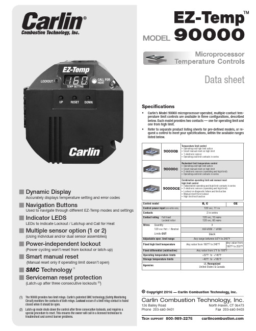
Data sheet126 Bailey RoadNorth Haven, CT 06473Phone 203-680-9401Fax 203-680-9403Carlin Combustion Technology, Inc.T ech support ©Copyright 2016 — Carlin Combustion Technology, Inc.Specifications• Carlin’s Model 90000 microprocessor-operated, multiple-contact tem-perature limit controls are available in three configurations, described below. Each model provides two contacts — one for operating limit and one from high limit.• Refer to separate product listing sheets for pre-defined models, or re-quest a control to meet your specifications, within the available ranges listed below.Control modelControl power input Contacts Contact ratingMN90000B 071916Model 90000B, C and CE Microprocessor Temperature Controls — Data sheetPower, Off – (How to enter = No power is applied to the red-white wire)• All lights and screen will be off. Power, On – (How to enter = Power applied to red-white wire)• System will power on and enter NORMAL OPERATION MODE Self-test – When power is applied, the 90000 performs a self-test, checkingsensor(s) and microprocessor and verifying limit contacts are open. The power-up test lasts from 3 to 5 seconds. The 90000 continues diagnos-tic checking during the operating cycle as well. Any self-check failure causes a lockout (see below). Call for Heat – When the temperature at the operating sensor is at or belowsetpoint minus fixed differential, the control powers the limit relay (break-on-rise contact closes; make-on-rise contact open).Stand By – When operating sensor reaches setpoint temperature or above,temp control will turn off the relay (break-on rise contact opens; make-on-rise contact closes). Normal Operation (Mode) – (How to enter = Initial starting mode)• The EZ-Temp will display the User Set Temperature. Display – (How to enter = Pressing UP or DOWN key in NORMAL MODE)• I n DISPLAY MODE, the EZ-Temp will display current temperature read-ing for 5 seconds, then return to NORMAL OPERATION Setting – (How to enter = Hold up and down buttons for 3 seconds while in NORMAL OPERATION) • I n SETTING MODE, the user is able to adjust the operating limit (via setting the set temperature). Once in this mode, the display will begin flashing the current set temperature. The display will increase one degree per UP or DOWN button push or 10 degrees per second when the button is held. Diagnostic – (How to enter = Power up the system with the UP and DOWNbuttons depressed. Once buttons are released, the system will move into diagnostic mode) • D IAGNOSTIC MODE displays recorded error codes. When powered in this mode, the display will show the newest recorded error code. As the DOWN key is pressed, the system will display error codes fromnewest to the oldest. When there are no more codes to display, the EZ-Temp will show a “E _ _” to indicate end of error codes. If the user continues to push the down button, the system will go back to the newest error code and begin displaying the error codes again from newest to oldest. The only way to exit this mode is to power cycle the system. To clear error codes (while in diagnostic mode), push and hold reset button for 3 seconds. To clear error codes (while in diagnostic mode), push and hold RESET button for 3 seconds.High Limit Temp – Fixed temp where the control will shut down and lockout(model dependent).High Limit Test – (How to enter = In NORMAL OPERATION, hold RESET, UPand DOWN buttons for 3 seconds) • D uring this operation, EZ-Temp will display a flashing 180 (or your current high temp). Pressing the DOWN button adjusts the high limit temperature. The high temp will decrease one degree for each press of the DOWN button. If the DOWN button is not pressed for a period of 10 seconds, the unit will return to normal operation. When the high limit is reached, the unit goes into hard lockout and displays the error code. Holding the RESET for 3 seconds clears the lockout and returns the high limit to default (180°). If the lockout condition has driven the unit into latchup, the RESET must be held for 30 seconds. Soft Lockout – (How to Enter = When any temperature sensor goes out ofrange or the system has detected a high temp condition and the primary and safety relays are still operational) • W hen in this state, it will display the error code but will leave thelockout LED off. If the condition that caused the soft lockout clears, the system will return to normal operation. Lockout – (How to Enter = Numerous Error Codes)• T he EZ-Temp will enter this state when an unsafe condition has oc-curred and the user must intervene and put the system in a safe state. Lockout can be cleared by pressing the RESET button for 3 seconds. Latchup – (How to Enter = Occurs after 3 LOCKOUTs have been detected)• T he system will enter a safe mode and will not exit the mode without user intervention. You can exit latchup mode by depressing the RESET button for thirty seconds. By exiting this way, the system will reset the lockout count back to zero.Set Temp – The target temperature of the appliance.Operation ModesMN90000B 071916Model 90000B, C and CE Microprocessor Temperature Controls — Data sheetMounting – 90000 controls mount to any standard well. Mountthe 90000 directly to a well (new or existing) with hardware supplied in the separate well mounting kit. See below for dimensions. Well Kits – Wells for 90000 sensors are available in the sizes shownbelow. Well kits include sensor mounting hardware designed to hold sensor securely in position. Sensors – Sensors are available separately for 90000.ConfigurationsError CodesError CodeReason01Primary (K2) relay is welded on. Note: If the control is reset from error code 01, the red LED will flash every 5 seconds indicating the control must be replaced.02Primary & Safety relays (K1 and K2) on. The control cannot be reset from error code 02 and must be replaced.03Primary & Safety relays (K1 and K2) are off 05Simulated High Temp lockout06Temp is above set high temp but below thermistor high (250°F)16AC line frequency out of toleranceError CodeReason20Temp sensor 1 out of range failure 21Temp sensor 2 out of range failure 22High limit temp sensor out of range failure 23Temp sensor 1 pin is open 24Temp sensor 2 pin is open 25High limit temp sensor is open07, 10, 11, 12, 13, 14, 15Internal hardware safety failure – unit should be replaced. Contact customer service for additional informa-tion. 1-800-989-22753"43/8"43/4"Model 90000B, C and CE Microprocessor Temperature Controls — Data sheetMN90000B 071916。
恩达富 NB-IoT 模块产品说明书
AzoteqFEATURES OF MA510-GL-00 Dimension: 22.2 x 20.2 x 2.1 mm Package: LCC + LGA, 86 Pin Operating frequency band:Cat.M1: B 1/B2/B3/B4/B5/B8/B12/B13/B14/B18/B19/B20/B25/B26/B27/B28/B66/B85Cat.NB2: B 1/B2/B3/B4/B5/B8/B12/B13/B18/B19/B20/B25/B26/B28/B66/B71/B85EGPRS: 850/900/1800/1900MHz GNSS: GPS / GLONASS / BeiDou / Galileo Power supply: 3.3 V ~ 4.5 V (typical 3.8 V) Operating temperature: -40 °C ~ +85 °C Cat.M1 (kbps): 589 (DL) / 1119 (UL) Cat.NB2 (kbps): 136 (DL) / 150 (UL) GPRS (kbps): 107 (DL) / 85.6 (UL) EDGE (kbps): 296 (DL) / 236.8 (UL) Antenna: Main x 1, GNSS x 1 Functional interfaces: SIM 1.8V / USB 2.0 x 1 / UART x 3, I2C, I2S, GPIO, SPI / ADC / System Indicator / ANT_TUNER Global certificationsAPPLICATIONSAsset trackingIndustrial monitoring and control Security systems Smart home Smart meteringAPPLICATIONS PC Peripherals IoT Mobile Application White Goods Home AutomationIQS620A IQS621IQS622IQS624The triple-mode (LTE Cat.M1, LTE Cat.NB2 and EGPRS), the dual-mode (LTE Cat.M1 and LTE Cat.NB2), as well as the single-mode module (LTE Cat.M1) are all compatible. The series is based on Qualcomm IC MDM9205, available with LCC and LGA footprint (22.2 x 20.2 x 2.1 mm), supports GNSS (GPS / GLONASS / BeiDou / Galileo), and has given all needed global certifications.The first generation of ProxFusion ® offers capacitive sensing, Hall-effect, IR, PIR, inductive, temperature and ambient light sensing.Replace up to 4 sensors with a single IC Reduce BOMLow Power Consumption High Reliability Less Board Space Less GPIO to MCU Reduce Cost The series is characterized by low power consumption and robust accessibility even inside buildings. In addition, it is very cost effective and has an enormous range, which opens up new possibilities for applications in cities or agriculture.The modules are primarily recommended for applications in which low data throughput rates have to be transmitted securely, like asset tracking, industrial monitoring and control, security systems, smart home, smart metering, etc.Fibocom has developed the brand new LPWA module series namedMA510-GL which will be available in several versions. The derivates enable your application to connect to the network types LTE Cat.M1, LTE Cat.NB2 and EGPRS.PIRH AL LI n du c it v eALSC a p a c i t i v eA c ti v eI RProxFusion ®HAVE A LOOKHAVE A LOOKHAVE A LOOKHAVE A LOOKHAVE A LOOKHAVE A LOOKHAVE A LOOK20CR08F-1-38ND-W 28CRG08-2-N50BD-W 28KUG04X-W 32-8C-2-W36CS08FN-21-N50BT-W 39KUG04XNT-2-W 40KT08-W 4028KSG08-WCSMS18S4.8-8S0.3-P580F CSMS29R8-8S0.6-P700F CMS40R5C-8N1-2A600R CLS50R14-16N3-T700-C32W150R CLS50RN18.2E-8F1.5-B380R CLS87S32.5-8F6-E500RCPA26D12-3.2R CPA36B515TU2C17W80VMW4015B-RRAC383G-7FA VMW6027B-8C464G-7FA32-8C-2-W CSMS18S4.8A-8S0.3-P580F 28CRG08-2-N50BD-W HAVE A LOOK HAVE A LOOK HAVE A LOOK HAVE ALOOK HAVE A LOOK HAVE A LOOK HAVE A LOOK HAVE A LOOK HAVE A LOOKHAVE A LOOK HAVE A LOOK HAVE A LOOK HAVE A LOOK HAVE A LOOK HAVE ALOOK HAVE A LOOKHAVE A LOOKHAVE A LOOKHAVE A LOOKLOCOSYS RTK-4671-SHDR/MHDR is a high-precision GNSS RTK solution targeting for the smart driving and lane level navigation markets. The newly designed LOCO II engine architecture is optimized to offer a seamless experience in dense urban canyons. The high-precision Positioning/Dead Reckoning receiver offers centimeter-accurate positioning and heading with low-power consumption, takes the shortest time to fix position and continues to work wherever they are.LOCOSYS RTK-4671-SHPF /MHPF is a high-precision GNSSRTK board for accurate positioning and heading and direction. It supports GPS, GLONASS, BeiDou, GALILEO, QZSS and SBAS constellations to improve the continuity and reliability of the RTK solution even in harsh environment. This board offers real-time, cost-efficient and cm-level-positioning. It supports flexible interfaces, inside great anti-jamming performance (thanks to multi-tone active interference compensator) for a variety of applications, such as precision navigation, precision agriculture, surveying and UAVs.APPLICATIONSAutonomous Vehicle Guidance Autonomous Vehicle Internet of Vehicles Unmanned Aerial Vehicles Precision Agriculture Hand-Held Device AGV Robotics V2V / V2X System Geographical Measurement Geographical Survey Points Offshore / Marine Applications TrackerAPPLICATIONSAutonomous Vehicle Guidance Unmanned Aerial Vehicles Precision Agriculture AGV Robotics V2X / ETC / 5G Station Structural / Land Monitoring Offshore / Marine ApplicationFEATURESSupports GPS, GLONASS, BeiDou, GALILEO and QZSS L1 Capable of SBAS (WAAS, EGNOS, MSAS) Precise navigation, positioning Great anti-jamming performance(due to multi-tone active interference canceller) Built-in LOCOSYS Dead Reckoning (ADR / UDR) both technology software Built-in MEMS sensor(3-axis gyroscope and 3-axis accelerometer) Supports odometer (wheel-tick pulse) inputFEATURESLow cost, commercial chip level, with high precision and accuracy Centimeter-level positioning in RTK mode Supports GPS, GLONASS, BeiDou, GALILEO and QZSS L1 Capable of SBAS (WAAS, EGNOS, MSAS) Precise navigation, positioning Great anti-jamming performance(due to multi-tone active interference compensator) Dual antenna input and precise heading calculation Current limited feature (limited to 50 mA typ.) 2 x 99 channels each independent signal chains Heading accuracy (RMS) < 0.2 degree Industrial operating temperature range -40 °C to +85 °C Low-power consumption and compact size Easy and simple to integrate LOCOSYS IATF 16949 certified production sitesRTK-4671-SHDR/MHDR not only supports GPS, GLONASS, Beidou, GALILEO, QZSS and SBAS, but also has a flash memory, TCXO, RTC crystal, LNA and SAW filter, and embedded MEMS sensors (6-axis accelerometers + gyros).Supports MEMS raw data output, high update rate(up to 100 Hz) Supports sensors data feed through the UART port Supports ADR / UDR automatic fast learning calibration Low-power consumption and compact size Current limited feature (limited to 50 mA typ.) with active GNSS antennas Industrial operating temperature range -40 °C to +85 °C Easy and simply to integrate LOCOSYS IATF 16949 certified production sitesHAVE ALOOKHAVE A LOOKHAVE A LOOKHAVE A LOOK@ SALES OFFICES IN EUROPESwitzerland − Novitronic Zurich:T +41/44 306 91 91info @novitronic.chFrance Paris:T +33/186653215france @ Lyon:T +33/186653215france2@Bulgaria Sofia:bulgaria @Spain Barcelona:T +34/93 217 31 44spain @ Hungary Budapest:T +361/2 97 41 91hungary @ Austria & Slovenia Brunn am Gebirge:T +43/1 665 25 25austria @ Romania Timisoara:romania @On September 12, 2019, the award ceremony of the magazine Elektronik for "Distributor of the Year" took place.1st placeActive Components:Technical Competence & Support2nd placeActive Components: Delivery service Volume3rd placeActive Components: Samples delivery serviceWe would like to thank you very much for your trust! Thanks to your votes we were awarded 3 prizes which we see as a confirmation of our efforts to support you as a reliable partner! We will continue to offer our customers the best possible service, from the component up to the finished solution for their applications.。
ST(伯纳德执行机构运行说明)

3
(图3) (图4) (图5)
5-行程限制开关的设置
本章与ST INTELLI+无关。事实上,开关配备有绝对位置编码器,并通过编程进行设置(参见 NR1112说明)。 5-1 行程限制开关相关说明与功能介绍(图3): 操作限制开关的凸轮组件位于一个圆柱体上,无需拆解。各凸轮之间可相互独立设置,白色和黑色 凸轮一般用于开阀和关阀方向行程限制开关,其它则留给选配的额外限制开关(2或4)使用。 凸轮操作方法: a)将螺丝刀插入按钮的孔内(按钮上的色圈与待设定的凸轮同色)。 b)轻轻下压,让凸轮脱离锁定位置。 c)转动螺丝刀,将凸轮旋转到能够触发限制开关为止。 d)松开螺丝刀,确保按钮回到原位,从而将凸轮锁定到所选位置。 5-2 行程限制开关的设定步骤: a)用手将阀门打到关闭位置。 b)设定“关阀”行程限制开关的凸轮。 按照与开阀位置相同的方式进行操作。 进行完整的电动开关阀操作,以检查阀门是否停止在正确的位置。 5-3 以扭矩限制器判定阀门关闭 “关阀”行程限制开关可用于对“开阀”扭矩限制器接点进行屏蔽,从而将阀体解离。这样即使此 后扭矩超过了最大设定值,也可确保安全无虞(参见第2页)。 按照与5.2节中相同的方式进行操作,期间应确保在电动关阀过程中,在执行器因触发“关阀”扭 矩限制器而停止前的短时间内,触发“关阀”行程限制开关并保持其触发状态。
两线制
两线或三线制
三相
图例:C1 = 开阀接触器;C2 = 关阀接触器
单相
断路器 + 熔断器
断路器 + 熔断器
热继电器
热继电器
电容器 如需其它版本(如VDC),请与我们联系
13
控制盘设计样例
中间部分表示的是执行器
停止
执行器
执行器
停止
- 1、下载文档前请自行甄别文档内容的完整性,平台不提供额外的编辑、内容补充、找答案等附加服务。
- 2、"仅部分预览"的文档,不可在线预览部分如存在完整性等问题,可反馈申请退款(可完整预览的文档不适用该条件!)。
- 3、如文档侵犯您的权益,请联系客服反馈,我们会尽快为您处理(人工客服工作时间:9:00-18:30)。
ST 车用MCU ST10F296E用户指南
意法半导体车用MCU ST10F296E 16-bit MCU with MAC unit, 832 Kbyte Flash memory and 68 Kbyte RAM
详情请下载:AotoST10F296E.pdf
Features■ High performance 16-bit CPU with DSPfunctions–31.25 ns instruction cycle time at 64 MHzmax CPU clock–Multiply/accumulate unit (MAC) 16 x 16-bitmultiplication, 40-bit accumulator–Enhanced boolean bit manipulationfacilities–Single-cycle context switching support■ Memory organization– 512 Kbyte Flash memory (32-bit fetch)– 320 Kbyte extension Flash memory(16-bit fetch)– 100 k erasing/programming cycles– Up to 16 Mbyte linear address space forcode and data (5 Mbytes with CAN or I2C)–2 Kbyte on-chip internal RAM (IRAM)– 66 Kbyte on-chip extension RAM (XRAM)– Programmable external bus characteristicsfor different address ranges–Five programmable chip-select signals–Hold-acknowledge bus arbitration support■ Interrupt–8-channel peripheral event controller forsingle cycle interrupt driven data transfer–16-priority-level interrupt system with 56sources, sampling rate down to 15.6 ns■ Timers–Two multi-functional general purpose timerunits with 5 timers■ Two 16-channel capture/compare units■ Analog-to-digital converter (ADC)– 32-channel 10-bit–3 μs minimum conversion time–TImer for ADC channel injection■ 4-channel PWM unit and 4-channel XPWM■ Serial channels– Two synchronous/asynch. serial channels– Two high-speed synchronous channels–I2C standard interface■ Two CAN 2.0B interfaces operating on one ortwo CAN busses (64 or 2 x 32 messageobjects, C-CAN version)■ Fa il-safe protection–Programmable watchdog timer–Oscillator watchdog■ On-chip bootstrap loader■ Clock generation– On-chip PLL and 4-12 MHz oscillator–Direct or prescaled clock input■ Real-time clock■ Up to 143 general purpose I/O lines–Individually programmable as input, outputor special function–Programmable threshold (hysteresis)■ Idle, power-down and stand-by modes■ single voltage supply: 5 V ±10% (embeddedregulator for 1.8 V core supply).。
