RCCP_T001_V2.6
AUTOSAR_SWS_XCP
Document Title Specification of Module XCP Document Owner AUTOSARDocument Responsibility AUTOSARDocument Identification No 412Document Classification StandardDocument Version 2.0.0Document Status FinalPart of Release 4.0Revision 3Document Change HistoryDate Version Changed by Change Description12.12.2011 2.0.0 AUTOSARAdministration ∙Added parameters for Event Channel and Timestamp configuration∙Added possibility to calculate memory consumption for ODT (DAQ & STIM) ∙ Restructuring configurationparameters for static & dynamic ODT ∙Added support for deactivation of transmission capabilities11.10.2010 1.1.0 AUTOSARAdministration ∙Add chapter 7.8 (Version check), RTE limitation, OS Counter Ref∙Remove InstanceID and known limitation (OS)07.12.2009 1.0.0 AUTOSARAdministration∙ Initial ReleaseDisclaimerThis specification and the material contained in it, as released by AUTOSAR, is for the purpose of information only. AUTOSAR and the companies that have contributed to it shall not be liable for any use of the specification.The material contained in this specification is protected by copyright and other types of Intellectual Property Rights. The commercial exploitation of the material contained in this specification requires a license to such Intellectual Property Rights.This specification may be utilized or reproduced without any modification, in any form or by any means, for informational purposes only.For any other purpose, no part of the specification may be utilized or reproduced, in any form or by any means, without permission in writing from the publisher.The AUTOSAR specifications have been developed for automotive applications only. They have neither been developed, nor tested for non-automotive applications.The word AUTOSAR and the AUTOSAR logo are registered trademarks.Advice for usersAUTOSAR specifications may contain exemplary items (exemplary reference models, "use cases", and/or references to exemplary technical solutions, devices, processes or software).Any such exemplary items are contained in the specifications for illustration purposes only, and they themselves are not part of the AUTOSAR Standard. Neither their presence in such specifications, nor any later documentation of AUTOSAR conformance of products actually implementing such exemplary items, imply that intellectual property rights covering such exemplary items are licensed under the same rules as applicable to the AUTOSAR Standard.Table of Contents1Introduction and functional overview (5)2Acronyms and abbreviations (6)3Related documentation (7)3.1Input documents (7)3.1.1Related standards and norms (8)4Constraints and assumptions (9)4.1Limitations (9)4.2Applicability to car domains (9)5Dependencies to other modules (10)5.1AUTOSAR RTE (BSW Scheduler) (10)5.2AUTOSAR FlexRay Interface (10)5.3AUTOSAR CAN Interface (10)5.4AUTOSAR SocketAdaptor (10)5.5AUTOSAR RTE (10)5.6AUTOSAR OS (10)5.7AUTOSAR Diagnostic Event Manager (10)5.8AUTOSAR Development Error Tracer (10)5.9File structure (11)5.9.1Code file structure (11)5.9.2Header file structure (11)6Requirements traceability (13)6.1General Requirements on Basic Software Modules (13)6.2Requirements on the XCP Basic Software Module (15)7Functional specification (16)7.1XCP on CAN (18)7.2XCP on FlexRay (19)7.3XCP on Ethernet (21)7.4Requirements on Debugging (22)7.4.1General Requirements (22)7.5Error classification (23)7.6Error detection (24)7.7Error notification (24)7.8Version checking (24)8API specification (26)8.1Imported types (26)8.2Type definitions (26)8.2.1Xcp_ConfigType (26)8.2.2Xcp_Transmission Mode Type (26)8.3Function definitions (27)8.3.1Xcp_Init (27)8.3.2Xcp_GetVersionInfo (28)8.4Call-back notifications (29)8.4.1Xcp_<module>RxIndication (29)8.4.2Xcp_<module>TxConfirmation (30)8.4.3Xcp_<Lo>TriggerTransmit (30)8.4.4Xcp_SetTransmissionMode (31)8.5Scheduled functions (32)8.5.1Xcp_MainFunction (32)8.6Expected Interfaces (32)8.6.1Mandatory Interfaces (32)8.6.2Optional Interfaces (33)8.6.3Configurable interfaces (33)9Sequence diagrams (35)9.1XCP on FlexRay (35)9.1.1Xcp on FlexRay Transmit (35)9.1.2Xcp on FlexRay Receive Indication (35)9.2XCP on CAN (36)9.2.1Xcp on CAN Transmit (36)9.2.2Xcp on CAN Transmit Confirmation (36)9.2.3Xcp on CAN Receive Indication (37)9.3XCP on Ethernet (38)9.3.1Xcp on Ethernet Receive Indication (38)10Configuration specification (39)10.1How to read this chapter (39)10.1.1Configuration and configuration parameters (39)10.1.2Variants (39)10.1.3Containers (40)10.1.4Specification template for configuration parameters (40)10.2Containers and configuration parameters (40)10.2.1Variants (41)10.2.2Xcp (42)10.2.3XcpGeneral (42)10.2.4XcpConfig (51)10.2.5XcpDaqList (52)10.2.6XcpDto (54)10.2.7XcpOdt (54)10.2.8XcpOdtEntry (55)10.2.9XcpDemEventParameterRefs (56)10.2.10XcpEventChannel (59)10.2.11XcpPdu (61)10.2.12XcpRxPdu (62)10.2.13XcpTxPdu (63)10.3Published Information (64)11Not applicable requirements (65)1 Introduction and functional overviewThis specification specifies the functionality, API and the configuration of the AUTOSAR Basic Software module XCPXCP is a protocol description (ASAM standard) between a master (tool) and a slave (device), which provides the following basic features:- Synchronous data acquisition (measurement)- Synchronous data stimulation (for rapid prototyping)- Online memory calibration (read / write access)- Calibration data page initialization and switching- Flash Programming for ECU development purposes- Every feature is optional and the access can be restricted- Various communications busses are supportedXCP was designed according to the following principles:- Minimal Slave resource consumption (RAM, ROM, runtime)- Efficient communication- Simple Slave implementation2 Acronyms and abbreviationsAcronym: Description:AUTOSAR AUT omotive O pen S ystem AR chitectureA2L File Extension for an ASAM 2MC Language FileASAM A ssociation for S tandardization of A utomation and M easuringSystemsBSW B asic S oft w areCAN C ontroller A rea N etworkCanIf CAN I nter f aceCTO C ommand T ransfer O bjectDAQ D ata A c Q uisition, Data AcQuisition PacketDTO D ata T ransfer O bjectECU E lectronic C ontrol U nitFrIf F lex R ay I nter f aceHIS H ersteller I nitiative S oftwareLPDU Data Link Layer PDUMCD M easurement C alibration and D iagnosticsMISRA M otor I ndustry S oftware R eliability A ssociationODT O bject D escriptor T ablePDU P rotocol D ata U nitRAM R andom A ccess M emoryROM R ead O nly M emorySchM Sch edule M anagerSVN S ub v ersio nSRS S oftware R equirements S pecificationSTIM DataStim ulation packetSW S oft w areSWS S oft w are S pecificationTCP/IP T ransfer C ontrol P rotocol /I nternet P rotocolTS T ime S tampUDP/IP U ser D atagram P rotocol /I nternet P rotocolURL U niform R esource L ocatorProtocolCalibrationXCP UniversalXML E x tensible M arkup L anguageISR I nterrupt S ervice R outineDEM D iagnostic E vent M anager (AUTOSAR BSW module)DET D evelopment E rror T racer (AUTOSAR BSW module)3 Related documentation3.1 Input documents[0] Basic Software Module Description TemplateAUTOSAR_TPS_BSWModuleDescriptionTemplate.pdf [1] List of Basic Software ModulesAUTOSAR_TR_BSWModuleList.pdf[2] AUTOSAR Layered Software ArchitectureAUTOSAR_EXP_LayeredSoftwareArchitecture.pdf [3] General Requirements on Basic Software ModulesAUTOSAR_SRS_BSWGeneral.pdf[4] Specification of RTE (BSW Scheduler)AUTOSAR_SWS_RTE.pdf[5] Specification of ECU ConfigurationAUTOSAR_TPS_ECUConfiguration[6] Specification of Memory MappingAUTOSAR_SWS_MemoryMapping.pdf[7] Specification of FlexRay InterfaceAUTOSAR_SWS_FlexRayInterface.pdf[8] Specification of CAN InterfaceAUTOSAR_SWS_CANInterface[9] Specification of Socket AdaptorAUTOSAR_SWS_SocketAdaptor[10] Requirements on XCP ModuleAUTOSAR_SRS_XCP.pdf[11] AUTOSAR OS Specification:AUTOSAR_SWS_OS3.1.1 Related standards and norms[12] ASAM XCP – The Universal Measurement and Calibration Protocol/index.php?option=com_content&task=view&id=136&Itemid= 18[13] ASAM XCP – Transport Layer Specification XCP on CAN/index.php?option=com_content&task=view&id=136&Itemid= 18[14] ASAM XCP – Transport Layer Specification XCP on Ethernet/index.php?option=com_content&task=view&id=136&Itemid= 18[15] ASAM XCP – Transport Layer Specification XCP on FlexRay/index.php?option=com_content&task=view&id=136&Itemid= 184 Constraints and assumptions4.1 LimitationsThe following XCP features are currently out of scope:- The XCP feature “Flash Programming for ECU development purposes” is currently out of AUTOSAR scope!- The SET_DAQ_ID command according to the XCP CAN Transport Layer Specification is not part of the AUTOSAE XCP module”- Currently, the AUTOSAR RTE does not offer APIs for direct communication with XCP- For further details concerning the supported feature set, please refer to [12] Please note:For the communications bus LIN, no ASAM XCP is specified.4.2 Applicability to car domainsn/a5 Dependencies to other modulesThis section describes the relations to other modules and files within the AUTOSAR basic software architecture. It contains brief descriptions of configuration information and services, which are required by the XCP module from other modules.5.1 AUTOSAR RTE (BSW Scheduler)The BSW Scheduler calls the main functions of the Xcp, which are necessary for the cyclic processes of the Xcp.5.2 AUTOSAR FlexRay InterfaceThe FlexRay Interface is used to transmit and receive XCP PDUs via FlexRay.5.3 AUTOSAR CAN InterfaceThe CAN Interface is used to transmit and receive XCP PDUs via CAN.5.4 AUTOSAR SocketAdaptorThe SocketAdaptor is used to transmit and receive XCP PDUs via Ethernet.5.5 AUTOSAR RTEThe RTE is used for copying calibration parameters from ROM/FLASH to RAM andto use the double pointered method5.6 AUTOSAR OSIn order to be able to use the time stamped feature of XCP, an AUTOSAR OS Counter is used.5.7 AUTOSAR Diagnostic Event ManagerIn order to be able to report production errors, the XCP has to have access to the Diagnostic Event Manager.5.8 AUTOSAR Development Error TracerIn order to be able to report development errors, the XCP has to have access to the error hook of the Development Error Tracer.5.9 File structure5.9.1 Code file structure[Xcp501]⌈The code file structure shall not be defined within this specification completely. At this point it shall be pointed out that the code-file structure shall include the following files named:- Xcp.c – general source code file of the module XCP- Xcp_Cfg.c – for pre-compile time configurable parameters- Xcp_Lcfg.c – for link time configurable parameters and- Xcp_PBcfg.c – for post build time configurable parameters.⌋(BSW00380, BSW00419, BSW00383, BSW00346, BSW158)These files shall contain all link time and post-build time configurable parameters.[Xcp500]⌈The module XCP shall access the location of the API of all used modules for pre-compile time configuration by either using of external declaration in includes of the used modules’ public header files <x>.h or by the code file Xcp_Cfg.c.⌋()5.9.2 Header file structure[Xcp502] ⌈Figure 5-1: XCP Header File Structure⌋(BSW00381, BSW00412, BSW00409,BSW00301)The XCP module shall include the Dem.h file. By this inclusion, the APIs to report errors as well as the required Event Id symbols are included. This specification defines the name of the Event Id symbols, which are provided by XML to the DEM configuration tool. The DEM configuration tool assigns ECU dependent values to the Event Id symbols and publishes the symbols in Dem_IntErrId.h.[Xcp503] ⌈All files related to the XCP module shall follow the naming conventionXcp[_<description>].<extension>⌋(BSW00300)[Xcp505]⌈The implementation of the XCP module shall provide the header file Xcp.h, which is the main module interface file. It shall contain all types and function prototypes required by the XCP module’s environment.⌋(BSW00302)[Xcp506]⌈The implementation of the XCP on CAN module shall provide the header file XcpOnCan_Cfg.h that shall contain the pre-compile-time configuration parameters.⌋()[Xcp507] ⌈The implementation of the XCP on FlexRay module shall provide the header file XcpOnFr_Cfg.h that shall contain the pre-compile-time configuration parameters.⌋()[Xcp508] ⌈The implementation of the XCP on Ethernet module shall provide the header file XcpOnEth_Cfg.h that shall contain the pre-compile-time configuration parameters.⌋()[Xcp509] ⌈The module shall include the Dem.h file.⌋()By this inclusion, the APIs to report errors as well as the required Event Id symbols are included. This specification defines the name of the Event Id symbols which are provided by XML to the DEM configuration tool. The DEM configuration tool assigns ECU dependent values to the Event Id symbols and publishes the symbols in Dem_IntErrId.h.6 Requirements traceability6.1 General Requirements on Basic Software ModulesRequirement Satisfied by BSW00344 Reference to link-time configuration Xcp741 BSW00404 Reference to post build time configuration Xcp742 BSW00405 Reference to multiple configuration sets Xcp803 BSW00345 Pre-compile-time configuration Xcp742 BSW159 Tool-based configuration Xcp102 BSW167 Static configuration checking Xcp103Xcp104Xcp105 BSW171 Configurability of optional functionality n/aBSW170 Data for reconfiguration of AUTOSAR SW-Components n/aBSW00380 Separate C-Files for configuration parameters Xcp501 BSW00419 Separate C-Files for pre-compile time configuration parameters Xcp501 BSW00381 Separate configuration header file for pre-compile time parameters Xcp502 BSW00412 Separate H-File for configuration parameters Xcp502 BSW00383 List dependencies of configuration files Xcp501 BSW00384 List dependencies to other modules Chapter 5 BSW00387 Specify the configuration class of callback function n/aBSW00388 Introduce containers Xcp101 BSW00389 Containers shall have names Chapter 10.2 BSW00390 Parameter content shall be unique within the module Chapter 10.2 BSW00391 Parameter shall have unique names Chapter 10.2 BSW00392 Parameters shall have a type Chapter 10.2 BSW00393 Parameters shall have a range Chapter 10.2 BSW00394 Specify the scope of the parameters Chapter 10.2 BSW00395 List the required parameters (per parameter) Chapter 10.2 BSW00396 Configuration classes Chapter 10.2 BSW00397 Pre-compile-time parameters Chapter 10.2 BSW00398 Link-time parameters Chapter 10.2 BSW00399 Loadable Post-build time parameters Chapter 10.2 BSW00400 Selectable Post-build time parameters Chapter 10.2 BSW00402 Published information Xcp807 BSW00375 Notification of wake-up reason n/aBSW101 Initialization interface Xcp803 BSW00416 Sequence of Initialization n/aBSW00406 Check module initialization Xcp811 BSW168 Diagnostic Interface of SW components n/aBSW00407 Function to read out published parameters Xcp807n/a BSW00423 Usage of SW-C template to describe BSW modules with AUTOSARInterfacesBSW00424 BSW main processing function task allocation Xcp823 BSW00425 Trigger conditions for schedulable objects n/aBSW00426 Exclusive areas in BSW modules n/aBSW00427 ISR description for BSW modules n/aBSW00428 Execution order dependencies of main processing functions n/aBSW00429 Restricted BSW OS functionality access Chapter 5.6 BSW00431 The BSW Scheduler module implements task bodies n/an/a BSW00432 Modules should have separate main processing functions forread/receive and write/transmit data pathBSW00433 Calling of main processing functions Xcp823 BSW00434 The Schedule Module shall provide an API for exclusive areas n/aBSW00336 Shutdown interface n/aBSW00337 Classification of errors Errorclassification BSW00338 Detection and Reporting of development errors Chapter 7.6Chapter 7.7 BSW00369 Do not return development error codes via API Chapter BSW00339 Reporting of production relevant error status Chapter BSW00417 Reporting of Error Events by Non-Basic Software n/aBSW00323 API parameter checking Chapter 8.3 BSW004 Version check Xcp749BSW00409 Header files for production code error IDs Xcp502BSW00385 List possible error notifications Chapter 7.5 BSW00386 Configuration for detecting an error Xcp754BSW161 Microcontroller abstraction n/aBSW162 ECU layout abstraction n/aBSW005 No hard coded horizontal interfaces within MCAL n/aBSW00415 User dependent include files n/aBSW164 Implementation of interrupt service routines n/aBSW00325 Runtime of interrupt service routines n/aBSW00326 Transition from ISRs to OS tasks n/aBSW00342 Usage of source code and object code Chapter 10.2.1 BSW00343 Specification and configuration of time Chapter 10.2 BSW160 Human-readable configuration data Xcp744BSW007 HIS MISRA C Xcp745BSW00300 Module naming convention Xcp503BSW00413 Accessing instances of BSW modules n/aBSW00347 Naming separation of different instances of BSW drivers n/aBSW00305 Self-defined data types naming convention Chapter 8.2 BSW00307 Global variables naming convention Xcp800BSW00310 API naming convention Xcp800BSW00373 Main processing function naming convention Xcp823BSW00327 Error values naming convention Xcp763BSW00335 Status values naming convention n/aBSW00350 Development error detection keyword Xcp753BSW00408 Configuration parameter naming convention Xcp800BSW00410 Compiler switches shall have defined values n/aBSW00411 Get version info keyword Xcp807Xcp808Xcp809Xcp810BSW00346 Basic set of module files Xcp501BSW158 Separation of configuration from implementation Xcp501BSW00314 Separation of interrupt frames and service routines n/aBSW00370 Separation of callback interface from API n/aBSW00348 Standard type header Chapter 5.9 BSW00353 Platform specific type header Chapter 5.9 BSW00361 Compiler specific language extension header Chapter 5.9 BSW00301 Limit imported information Xcp502BSW00302 Limit exported information Xcp505BSW00328 Avoid duplication of code n/aBSW00312 Shared code shall be reentrant n/aBSW006 Platform independency n/aBSW00357 Standard API return type Chapter 8.3 BSW00377 Module specific API return types n/aBSW00304 AUTOSAR integer data types Chapter 8.3 BSW00355 Do not redefine AUTOSAR integer data types Chapter 8.3 BSW00378 AUTOSAR boolean type Chapter 8.3 BSW00306 Avoid direct use of compiler and platform specific keywords n/aBSW00308 Definition of global data Xcp760BSW00309 Global data with read-only constraint n/aBSW00371 Do not pass function pointers via API n/aBSW00358 Return type of init() functions Xcp803BSW00414 Parameter of init function Xcp803BSW00376 Return type and parameters of main processing functions Chapter 8.5 BSW00359 Return type of callback functions Chapter 8.4 BSW00360 Parameters of callback functions n/aBSW00329 Avoidance of generic interfaces n/aBSW00330 Usage of macros / inline functions instead of functions n/aBSW00331 Separation of error and status values n/aBSW009 Module User Documentation n/aBSW00401 Documentation of multiple instances of configuration parameters n/aBSW172 Compatibility and documentation of scheduling strategy n/aBSW010 Memory resource documentation n/aBSW00333 Documentation of callback function context n/aBSW00374 Module vendor identification Xcp807BSW00379 Module identification Xcp807BSW003 Version identification Xcp807BSW00318 Format of module version numbers Xcp807BSW00321 Enumeration of module version numbers n/aBSW00341 Microcontroller compatibility documentation n/aBSW00334 Provision of XML file Xcp751BSW00435 Header File Structure for the Basic Software Scheduler Xcp747BSW00436 Module Header File Structure for the Memory Mapping Xcp7486.2 Requirements on the XCP Basic Software ModuleRequirement Satisfied by BSW429001 Location of XCP within the architecture Xcp701BSW429002 API usage Xcp712, Xcp714,Xcp720, Xcp734 BSW429003 Unique PDU-ID Xcp702BSW429004 XCP Specification Version 1.1 Xcp703BSW429005 XCP on CAN Xcp713BSW429006 XCP on FlexRay Xcp719BSW429007 XCP on Ethernet Xcp733BSW429008 A2L Support n/aBSW429009 Synchronous data acquisition Xcp705BSW429010 Synchronous data stimulation Xcp707BSW429011 Block communication mode Xcp711BSW429012 Interleaved communication mode Xcp710BSW429013 Dynamic data transfer configuration Xcp706BSW429014 Timestamped Data transfer Xcp709BSW429015 Bypassing Xcp761BSW429016 Seed & Key Xcp766BSW429017 XCP Initialization Xcp8037 Functional specificationThe specification of the module XCP shall define all parameters and interfaces, which are required to use the ASAM XCP protocol specification within an AUTOSAR environment.Description:Black arrows: Data Path (Signals/Pdus)Orange arrows: Control Path (FlexRay Interface)[Xcp701]⌈The AUTOSAR XCP Module be located above the bus specific Interfaces in case of FlexRay and Can. In case of Ethernet, the AUTOSAR XCP module shall be located above the Socket Adaptor.⌋(BSW429001)[Xcp702]⌈For transmitting and receiving of XCP messages, unique PDU-IDs shall be used. ⌋(BSW429003)[Xcp703]⌈The AUTOSAR XCP Module shall support the ASAM XCP Specification Version 1.1.⌋(BSW429004)[Xcp705]⌈The AUTOSAR XCP Module shall support the basic feature “Synchronous data acquisition (measurement) “. Please refer to [13]⌋(BSW429009)[Xcp706]⌈The AUTOSAR XCP Module shall support the feature “Dynamic DAQ Configuration”. according to [13]⌋(BSW429013)[Xcp707]⌈The AUTOSAR XCP Module shall support the basic feature “Synchronous data stimulation” according to [13]⌋(BSW429010)[Xcp708]⌈The AUTOSAR XCP Module shall support the basic feature “Online memory calibration (read / write access) “, according to [13]⌋()[Xcp709]⌈The AUTOSAR XCP Module shall support the feature “Timestamped Data Transfer“, according to [13]⌋(BSW429014)[XCP 768]⌈The ECU local time shall be derived from the AUTOSAR OS.⌋()[Xcp711]⌈The AUTOSAR XCP Module shall support the feature “Block communication mode“, according to [13]⌋(BSW42911)[Xcp761]⌈The AUTOSAR XCP Module shall support the feature “Bypassing“, according to [13]⌋(BSW429015)[Xcp766]⌈The AUTOSAR XCP Module shall support the feature “Seed & Key” according to [13]⌋(BSW429016)[Xcp712]⌈For sending and receiving of calibration data, the sending and receiving APIs specified within the AUTOSAR BSW Bus Interfaces (FlexRay Interface, CAN Interface, TCP/IP Socket Adaptor) shall be used. Please refer to chapter 7.1, 7.2 and 7.3.⌋(BSW429002)7.1 XCP on CAN[Xcp713]⌈The AUTOSAR XCP Module shall support the CAN communications bus according to [14]⌋(BSW429005)[Xcp714]⌈XCP data sent and received via CAN, the PDUs have to be transmitted and received using the transmitting and receive APIs provided by the AUTOSAR CAN Interface, according to [9]⌋(BSW429002)[Xcp715]⌈For sending and receiving XCP data via CAN, at least two different CAN identifiers have to be configured to be used by XCP.⌋()[Xcp716]⌈Performance information shall be exchanged between the XCP master and XCP slave using the parameters according to [14]⌋()[Xcp718]⌈The XCP Module shall support the GET_SLAVE_ID command according to [14]⌋()7.2 XCP on FlexRay[Xcp719]⌈The AUTOSAR XCP Module shall support the FlexRay communications bus according to [16]⌋(BSW429006)[Xcp720]⌈XCP data sent and received via FlexRay, the PDUs have to be transmitted and received using the transmit and receive APIs provided by the AUTOSAR FlexRay Interface according to [8].⌋(BSW429002)[Xcp721]⌈All XCP on FlexRay LPDUs always are event driven. Please refer to Chapter 1.1.2 “FlexRay Frame Type” of [16]⌋()[Xcp722]⌈The hardware buffers (of the FlexRay Communication Controller) XCP uses for data transmission and reception are assigned exclusively to the XCP module.⌋()Note:This restriction prevents disturbances of ongoing FlexRay communication.[Xcp723]⌈The usage of FlexRay Communication Controller’s hardware buffers shall be configured by the corresponding parameters according to [16]⌋()[Xcp724]⌈The FlexRay PDU length used by the AUTOSAR XCP module shall be set using the corresponding parameters according to [16]⌋()[Xcp725]⌈LPDU_IDs which shall be routed to the AUTOSAR XCP module (using the AUTOSAR Bus Interface) have to be defined by the system designer. ⌋()[Xcp726]⌈The ASAM MCD 2MC description file (i.e. A2L file) describes to which extent the XCP-dedicated buffers of a specific slave can be configured for XCP communication.⌋()[Xcp728]⌈The XCP master gets the information about the XCP dedicated FlexRay Communication Controller buffers from the ASAM MCD 2MC description file. ⌋()[Xcp729]⌈Limitations due to the usage of multiple XCP slaves on the FlexRay communications bus shall be taken into consideration by the system designer. Please refer to [16].⌋()[Xcp730]⌈Depending upon the requirements on sequencing correctness, alignment and net data throughput, different header types are possible. Please refer to Chapter 1.4.1 ”Header” of [16]⌋()[Xcp731]⌈For XCP on FlexRay, the Tail consists of a Control Field containing optional FILL bytes according to [16].⌋()[Xcp732]⌈The AUTOSAR XCP module shall be able to pack multiple XCP messages into one FlexRay Frame according to [16].⌋()7.3 XCP on Ethernet[Xcp733]⌈The AUTOSAR XCP Module shall support the Ethernet communications bus according to [15]⌋(BSW429007)[Xcp734]⌈XCP data sent and received via Ethernet, the PDUs have to be transmitted and received using the transmitting and receive APIs provided by the AUTOSAR Socket Adaptor according to [10].⌋(BSW429002)[Xcp735]⌈The AUTOSAR XCP slave connected by Ethernet and TCP/IP or UDP/IP is addressed by its IP Address and Port number.⌋()[Xcp736]⌈The AUTOSAR XCP slave only accepts one connection at the time. ⌋()[Xcp737]⌈If the socket is closed while in XCP connected state, the slave device will perform an XCP disconnect, which means that all data acquisition will be stopped.⌋()[Xcp738]⌈The addressing scheme is defined according to [15]⌋().[Xcp739]⌈The header and tail of an XCP on Ethernet message have to be set according to [15]⌋()[Xcp740]⌈The upper performance limit depends on the protocol stack of the host system. The corresponding parameters defined according to [15] have to be set.⌋()[Xcp710]⌈The AUTOSAR XCP Module shall support the feature “Interleaved communication mode“, according to according to [15]⌋(BSW429012)7.4 Requirements on Debugging[Xcp760]⌈Each variable that shall be accessible by AUTOSAR Debugging, shall bedefined as global variable.⌋(BSW00308)[Xcp759]⌈All type definitions of variables which shall be debugged, shall be accessible by the header file Xcp.h⌋()[Xcp762]⌈The declaration of variables in the header file shall be such that it is possible to calculate the size of the variables by C-"sizeof".⌋()[Xcp765]⌈Variables available for debugging shall be described in the respectiveBasic Software Module Description.⌋()[Xcp764]⌈The internal XCP states shall be available for debugging.⌋()In general, it is not necessary/intended for AUTOSAR debugging, that SWS documents define specific variables.7.4.1 General Requirements[Xcp741]⌈Link-time and post-build-time configuration data shall be implemented as read-only data structures. Link-time configuration data shall be immediately referenced by the implementation, the start-address of post-build-time configuration data shall be passed during module initialization⌋(BSW00344)[Xcp742]⌈The XCP module shall support pre-compile time, link-time and post-build-time configuration.⌋(BSW00404, BSW00345)[Xcp744]⌈The description of the configuration and initialization data itself is not part of this specification but very implementation specific. The generated configuration data should be “human-readable”.⌋(BSW160)。
广州致远电子ZM602系列Wi-Fi模块数据手册说明书
©2022 Guangzhou ZHIYUAN Electronics Co., Ltd.ZM602系列Wi-Fi 模块数据手册Wi-Fi 模块DS01010101 1.2 Date:2022/9/16—————————————— 概述 ZM602系列Wi-Fi 模块是广州致远电子有限公司基于博流BL602系列芯片开发的高性能Wi-Fi+BLE 模块产品。
产品支持IEEE802.11 b/g/n 三种Wi-Fi 通信协议,支持无线热点、无线客户端、无线热点+无线客户端三种工作模式,采用20MHz 标准带宽,可以提供最大72.2Mbit/s 物理层速率。
此外,产品同时具备蓝牙通信功能,支持蓝牙5.0通信协议。
ZM602系列Wi-Fi 模块将完整的射频收发电路集成在一个模块上,同时支持Wi-Fi 和BLE 两种通信模式。
模块的射频输出支持IPEX 座连接外部天线或者直接使用模块自带的PCB 天线模块,使用十分灵活,用户可以根据自己的需求进行选择。
模块与主控设备通过UART 或者SDIO 接口进行通信,简单方便,可以帮助用户产品更快的投入市场,增加用户产品的竞争力。
———————————— 产品应用 ◆ 工业数据采集 ◆ 物联网智能终端 ◆ 智能家居 ◆ 智能遥控器————————————— 产品图片———————————— 产品特性 ◆ 频率范围:2400~2483.5MHz ◆ 无线协议:IEEE 802.11 b/g/nBLE 5.0◆ 工作电压:3.0~3.6 V◆ 发射功率:************************** ************* 4dBm@BLE◆ 接收灵敏度:***************************************-97dBm@BLE◆ 射频输出:PCB 天线、IPEX 连接器 ◆ 通信接口:UART 或SDIO ◆ 温度范围:-30~+85℃———————————— 订购信息 注:见选型表©2022 Guangzhou ZHIYUAN Electronics Co., Ltd.修订历史文档版本 日期 原因V1.002022.04.25首次发布 V1.012022.08.17增加产品实物图; 更新产品选型表;优化产品尺寸图; 优化引脚定义说明; 更新BLE 发射功率; 新增包装信息;目录1. 产品简介 (1)1.1概述 (1)1.2产品特性 (1)1.3典型应用 (2)1.4产品选型表 (2)2. 外观尺寸 (3)3. 引脚定义 (4)3.1UART接口 (4)3.3SDIO接口 (7)4. 性能参数 (9)4.1串口波特率 (9)4.2射频性能 (9)4.3电气性能 (11)5. 硬件设计注意事项 (12)5.1UART接口系统设计 (12)5.1.1最小系统 (12)5.1.2推荐系统 (12)5.2SDIO接口系统设计 (13)5.2.1最小系统 (13)5.2.2推荐系统 (13)5.3电源设计 (13)5.4PCB布板注意事项 (14)5.5RF设计指导 (15)5.5.1外接天线使用指导 (15)5.5.2PCB天线使用指导 (15)6. 生产指导 (17)6.1推荐生产回流温度曲线 (17)6.2推荐生产回流温度时间对照表 (17)7. 包装信息 (18)8. 免责声明 (19)1. 产品简介1.1 概述ZM602系列Wi-Fi模块是广州致远电子有限公司基于博流BL602系列芯片开发的高性能Wi-Fi+BLE模块产品。
北京金朗鸿新信息技术有限公司 STM32F103RCT6 核心板 使用说明 V1.0.1说明书
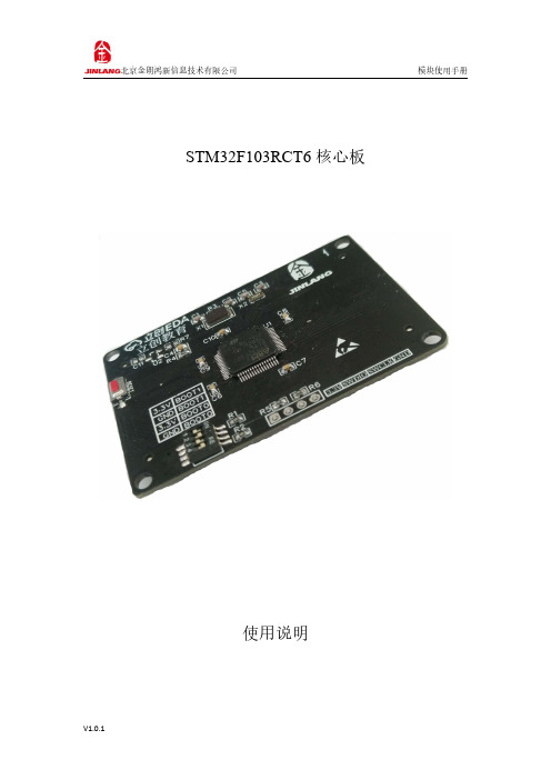
STM32F103RCT6核心板使用说明STM32F103RCT6核心板模块说明:该模块核心处理器为ST(意法半导体)公司的Cortex-M3架构内核的32位处理器,采用封装LQFP-64的嵌入式单片机,具体资源配置参考STM32F103RCT6数据手册。
技术参数:1、工作电压2V~3.6V2、独立SWD下载3、I/O全部引出4、除下载外采用全贴片元件节省空间5、拥有上电复位和按键复位两种选择(默认按键复位)6、板对板连接器方便更换以及二次开发7、启动方式采用拨码开关调节8、尺寸:60mm X42mm实物图:功能介绍:1、STM32F103RCT6:是ST公司的Cortex-M3架构内核的32位处理器封装为LQFP-64的单片机2、该部分为核心板板载的复位按键,当STM32F1系统需要复位时,可按下复位键,死机时可操作此按键3、在ISP下载电路中,我们需要配置BOOT引脚,有关BOOT引脚不同的配置会产生不同的启动方式,具体见表格4-1BOOT配置。
BOOT0BOOT1启动方式启动说明0X内部FLASH 用户闪存存储区,也就是FLASH 启动10系统存储器系统存储器启动,用于串口下载11内部SRAM SRAM启动,用于SRAM中调试代码4、由于STM32支持SWD调试,该部分为SWD下载,该模式只需要2个I/O 口,节约IO口数量,当我们的进行实验时,如果占用的IO口过多,导致JTAG 无法下载,我们选择SWD模式下载,JTAG模式与SWD模式实现的功能是一致的。
原理图:1、最小系统2、电源滤波3、BOOT4、复位5、SWD下载6、背部连接器封装图:注意事项:该核心板需要配合有同样连接器的底板使用,可进行选购或开发者自行设计(要注意连接器方向),此核心板电源电压为3.3V。
如高于额定电压值会将单片机烧毁。
SWMRCR-01 载波硬路由核心模块产品说明书
SWMRCR-01载波硬路由核心模块产品说明书SWMRCR-01载波路由核心模块产品说明书珠海中慧微电子有限公司2013年1月版权声明本资料是为了让用户根据用途选择合适的珠海中慧微电子有限公司(以下简称中慧微电子)的产品而提供的参考资料,不转让属于中慧微电子或者第三方所有的知识产权以及其他权利的许可。
在使用本资料所记载的信息并对有关产品是否适用做出最终判断前,请您务必将所有信息作为一个整体系统来评价。
对于本资料所记载的信息使用不当而引起的损害、责任问题或者其他损失,中慧微电子将不承担责任。
未经中慧微电子的许可,不得翻印或者复制全部或部分本资料的内容。
今后日常产品的更新会在适当的时候发布,恕不另行通知。
在购买本资料所记载的产品时,请预先向中慧微电子确认最新信息,并请您通过各种方式关注中慧微电子公布的信息,包括中慧微电子的网站()。
如果您需要了解有关本资料所记载的信息或产品的详情,请与珠海中慧微电子有限公司的技术服务部门联系,我们会为您提供全方位的技术支持。
版权所有:珠海中慧微电子有限公司© Copyright 2012珠海中慧微电子有限公司保留随时修改本说明书的权利是珠海市中慧微电子有限公司的注册商标。
本说明书中出现的其它商标,归商标所有者所有。
目录1产品概述 (1)1.1简介 (1)1.2主要技术指标 (1)1.3主要应用 (1)1.4主要特点 (1)2工作原理框图 (2)3接插座 (2)3.1接插座与集中器相连 (3)3.2接插座与电力猫相连 (3)4结构尺寸 (4)5安装说明 (4)6贮存与运输 (5)7保证期限 (5)1产品概述1.1简介为了简化与规范集中器的载波通信与路由管理接口,中慧微电子研发了载波硬路由核心模块SWMRCR-01,简称路由板(见图1)。
其符合了国家电网公司和南方电网公司的电力用户用电信息采集系统相关规范。
通过自组网通信路由算法,它记忆并存储各个子节点的相位、中继路径等节点路由信息,并根据信道状态以及信号品质对各电表的中继节点进行动态维护、优化路由表,满足了载波系统对网络路由管理的高度智能化要求。
VC-01-Kit 规格书说明书
VC-01-Kit规格书V1.0.0VC- -Kit规格书版本V . .版权 ©文件履历表目录1.产品概述 (4)1.1.特性 (5)2.主要参数 (6)2.1.静电要求 (6)2.2.电气特性 (7)2.3.功耗 (7)3.外观尺寸 (8)4.指示灯及按键说明 (9).管脚定义 (10).原理图 (12).产品相关型号 (13)8.固件烧录方式说明 (13)9.产品包装信息 (14)10.联系我们 (14)免责申明和版权公告 (15)注意 (15)1.产品概述VC-01-Kit是针对VC-01模组设计的开发板,该底板与VC-02-Kit共用。
开发板上集成了CH340C串口转USB芯片,提供基础的调试接口及USB升级接口;唤醒灯及冷暖灯的设计,提供了状态指示及控制指示,且方便调试简单的控制功能。
VC-01是深圳市安信可科技有限公司开发的一款低成本纯离线语音识别模组。
该模组使用云知声推出的语音芯片US516P6,在语音识别技术上不断优化和创新算法,离线识别算法与芯片架构深度融合,为客户提供超低成本的离线语音识别方案,可广泛且快速应用于智能家居,各类智能小家电,86盒,玩具,灯具等需要语音操控的产品。
US516P6芯片采用32bit RSIC架构内核,并加入了专门针对信号处理和语音识别所需要的DSP指令集,支持浮点运算的FPU运算单元,以及FFT加速器。
VC-01支持150条本地指令离线识别,支持RTOS轻量级系统,具有丰富的外围接口,以及简单友好的客制化工具。
图1US516P6芯片架构图1.1.特性内核32bit RISC内核,运行频率240MHz支持DSP指令集以及FPU浮点运算单元FFT加速器:最大支持1024点复数FFT/IFFT运算,或者是2048点的实数FFT/IFFT 运算云知声定制化语音算法算子存储内置242KB高速SRAM内置2MB FLASH音频输入输出灵活配置支持 . / . / . V IO支持1路模拟Mic输入,SNR≥94db支持双声道DAC输出支持中英文语音指令供电和时钟支持5V电源输入内置5V转3.3V,3.3V转1.2V LDO为芯片供电RC 12MHz时钟源和PLL锁相环时钟源内置POR(Power on Reset),低电压检测和看门狗外设所有GPIO均可配置为外部中断输入和唤醒源1个全双工UART最高速率3Mbps。
丰田EPC xt_EPC_01

VIN代码的组成 VIN车辆识别代码,共17位; Vehicle Identification Number VIN=WMI+VDS+VIS 例如:①JT25XV3E2N3326237 ②4T1GK12E7SU092125 ③LTVBA433330034571
WMI的组成和含义
WMI世界制造厂代码,1---3位; 第1位:生产国代码 1、4---美国;J---日本;K---韩国;W---德国; V---法国;L---中国 第2位:制造厂代码 G---GM;F---FORD;T---TOYOTA; H---HONDA;A---AUDI;B---BMW 第3位:车型类型 1---小客车(美国);2---载人小客车 ;3---多 功能车,MPV;4---货车;5---开发车型或非完 整车型;A---货车;X---乘用小客车(美国)
09-01 11-01 11-02 11-03 11-04 11-05 11-06 11-07 12-01 13-01 13-02 15-01 15-02 16-01
标准工具 发动机总成 气缸曲柄总成 发动机大修包总成 气缸盖总成 气缸体总成 正时齿轮盖 发动机支架 PVC阀 曲柄连杆 凸轮轴、气门部分 机油泵 机油滤清器 水泵
0---70年 6---76年 C---82年 J---88年 1---71年 7---77年 D---83年 K---89年 2---72年 8---78年 E---84年 L---90年 3---73年 9---79年 F---85年 M---91年 4---74年 A---80年 G---86年 N---92年 5---75年 B---81年 H---87年 P---93年 省略I、O、Q、U、Y、Z不用。
STM32固件库使用手册_v3.5版本

8175 TX-I O 模块 TXM1.6R TXM1.6R-M 说明书

8175TX-I/O™Relay modules TXM1.6RTXM1.6R-M∙Two fully compatible versions:– TXM1.6R:– 6 volt-free relay outputs– Individual I/O point signaling with green I/O status LED– TXM1.6R-M: As TXM1.6R, but with the following additional features– Three-color I/O status LED (red, yellow or green)– Local override (to ISO 16 484-2)∙ 6 relay outputs, which can be individually configured as:– Maintained contact or pulse, 1 … 3-stage– Three-position control output with stroke algorithm∙Mixed voltages (AC 250 V mains voltage and SELV/PELV 24 V) as well asmixed phases are permitted on adjacent I/O points of the module∙Compact DIN format, small footprint∙ Separate terminal base and plug-in I/O module for convenient handling– Self-establishing bus connection for maximum ease of installation– Terminal isolation function for fast commissioning– I/O module replaceable in seconds, without rewiring and without affectingthe full functioning of the remaining I/O modules∙Terminal strips are required to connect N and PE of the field devices∙Simple strategy for operation and display– I/O status LED for each I/O point– LEDs for fast diagnostics∙Double-sided labels for identification of all I/O pointsCM2N8175en_112/10FunctionsThe modules support the following I/O functions:Signal type (TRA)Signal type DescriptionBO Relay NO 250V BO Relay NC 250V Q250Maintained contact relay, changeover contact N/O, N/C contact BO Pulse On-Off Q250-P Q250A-P On/off pulse Q250-P With self-latching and 2 channels Q250A-PWith dual-winding switchBO Pulse *)PulseMO Steps Q-M1…M4Multistate maintained contact, 1…6-stage mutually exclusive electronic relay interlock MO Pulse Q250-P1…P5Multistate pulse, 1…5-stagemutually exclusive electronic relay interlock BO 3-Pos RelayY250TPulse, control signal, three-position output,internal algorithm for stroke running time*) DESIGO V4, V5: Use MO Q250-P1.For a detailed description of these functions, please refer to document CM110561,"TX-I/O™ functions and operation".∙Q250B Use TXM1.6RL with BO Bistable NO / NCFor switched current <100mA, see CM110563, Replacement of legacy signal types.∙QD Feedback must be implemented using separate digital inputse.g. with TXM1.8D, see CM110563.CompatibilitySupport of signal types and functions in different building automation and control systems: see TX-I/O Engineering and installation manual, CM110562Type summary Relay module TXM1.6RRelay module TXM1.6R-M with local overrideThe terminal base and the plug-in I/O module are interconnected and delivered in the same box.The available accessories include address keys, label sheets, and spare transparent label holders. Refer to data sheet CM2N8170.NotesASNDeliveryAccessories3/10Technical and mechanical designFor a description of the features common to all TX-I/O™ modules, please refer to the TX-I/O™ Engineering and installation manual, document CM110562.Indicators and operator controlsConnection terminals (No. 1 screwdriver for slotted or recessed-head * screws)with test pickup (for 1.8...2 mm pins) and terminal number Signal designationOverride status LEDs (yellow)Address key and module status LEDI/O point numbersOverride button (TXM1.6R-M only)I/O status LEDs (TXM1.6R: green;TXM1.6R-M: colors can be configured, green/yellow/red)* Combined slotted / recessed-head screws from mid-2012∙The I/O status LEDs indicate the status of the relays ∙The LEDs on the TXM1.6R are green.∙In the case of the TXM1.6R-M the LEDs are three-colored. If the I/O function supports it, the module can display Alarm = red and Service = yellow, besides Normal = green∙The LEDs are also used for diagnostics∙The module status LED illuminates the transparent address key∙The (green) LED shows the module status as a whole (as opposed to the I/O points)∙It is also used for diagnostics∙The module operates only with the address key inserted∙The module address is mechanically encoded in the address key∙When replacing the plug-in I/O module, the address key must be swiveled outward. It remains plugged into in the terminal base.∙The relay contacts of the individual I/O points are volt-free, and are notinterconnected. The switched voltage must be provided separately for each I/O point.∙Mixed voltages (AC 250 V mains voltage and SELV/PELV 24 V) as well as mixed phases are permitted on adjacent I/O points of the moduleI/O status LEDsModule status LEDsAddress keyTerminals4/10Local override (TXM1.6R-M only)∙Pressing an override button in the middle enables/disables local override∙Pressing "+" for one of the I/O points activates the relay or switches control to the next stage up (depending on function)Repeated or sustained pressure switches several stages until the function stops at the highest stage.∙Pressing "–" for one of the I/O points deactivates opens the relay or switches control to the next stage down (depending on function)Repeated or sustained pressure switches several stages until the function stops at the lowest stage.∙The yellow "Override" LED indicates that local override is active∙All safety-relevant functions must be implemented with external solutions ∙The local override must not be used for safety shutdown operations∙In compliance with the standard (ISO 16 484-2, Section 3.110), the module executes all local overrides directly, without safety precautions or interlocks.→ Full responsibility lies with the operator.←Module labelingThe plug-in I/O module has a removable transparent cover (the label holder) for insertion of a label.DisposalThe device is classified as waste electronic equipment in terms of the European Direc-tive 2012/19/EU and should not be disposed of as unsorted municipal waste.The relevant national legal rules are to be adhered to.Regarding disposal, use the systems setup for collecting electronic waste.Observe all local and applicable laws.Override buttonOverride status LEDEngineering, mounting, installationPlease refer to the following documentsDocument NumberTX-I/O™ functions and operation CM110561TX-I/O™ Engineering and installation manual CM110562Replacement of legacy modules CM110563 *)*) Login with Siemens account necessary.MountingThe TX-I/O™ devices can be installed in any orientation:It is important to provide adequate ventilation so that the admissible ambienttemperature (max. 50°C) is not exceeded.Technical dataSupply(bus connector on side)Operating voltageExtra low voltage SELV or PELVin accordance with HD384DC 21.5 ... 26 VMax. power consumption TXM1.6R 1.7 WTXM1.6R-M(for the sizing of power supplies, see CM110562)1.9 WProtection Bus connector on side No protection against shortcut andincorrect wiring with AC/DC 24 VSwitching outputs Number of switching outputs 6 (changeover contact)External fuse protection for incoming cable∙Slow blow fusible link Max. 10 A∙Circuit breaker Max. 13 ACircuit breaker tripping characteristic Type B, C or D to EN 60898 Contact data for AC Voltage range min. AC 12V max. AC 250VCurrent,resistive load max. 4ACurrent, inductive load (cos phi≥ 0.6)max. 3ASwitching current min. 1 mA at AC 250 Vmin. 10mA at AC 12VCurrent on make max. 20 A during max. 10 msmax. 10A during max. 1sFor UL applications 3 FLA, 9 LRA, 1/4 HP, 4 (3) A Contact data for DC Voltage range min. DC 12V, max. DC 30VCurrent, resistive load max. 3 A at DC 30 Vmin. 10mA at DC 12VCurrent on make max. 3 AService life of contact With 0.1 A resistive8 million switching operations for AC 250 V With 0.5 A resistive 2 million switching operationsWith 4.0 A resistive(N/O)0.2 million switching operationsReduction factor with inductive load(cos phi≥ 0.6)0.6 (max. 3 A inductive)Insulation resistance Reinforced insulation between relay outputs andsystem electronicsAC 3750 V, to EN 60 730-1Mixed voltages (AC 250 V mains voltage and SELV/PELV 24 V) as well asmixed phases are permitted on adjacent I/O points of the modulePermitted orientation5/10Connection terminals Mechanical designSolid conductorsStranded conductors without connector sleevesStranded conductors with connector sleeves(DIN46228/1)Cage clamp terminals1 x 0.5 mm2to 4mm2or 2 x 0,6 mm∅ to 1.5 mm2 1 x 0.5 mm2 to 2.5 mm2or 2 x 0,6 mm∅ to 1.5 mm2 1 x 0.25 mm2 to 2.5 mm2 or 2 x 0,6 mm∅ to 1.5 mm2Screwdriver No. 1 Screwdriver for slotted orrecessed-head * screwswith shaft diameter ≤ 4.5 mm* Combined slotted / recessed-head screws from mid-2012Max. tightening torque0.6 NmTest pickups (terminals)For pin diameter 1 x 1.8 … 2.0 mmLocal override(TXM1.6R-M only)Local override device ISO 16 484-2, Section 3.11Classification to EN 60730Mode of operation of automatic electrical controlsContamination levelMechanical designType 12Devices are suitable for use in equip-ment with protective class I and IIHousing protection standard Protection standard to EN 65029Front-plate components in DIN cut-outTerminal baseIP30IP20Ambient conditions OperationClimatic conditionsTemperatureHumidityMechanical conditions To IEC 60721-3-3 Class 3K5-5...50 °C5…95 % rh Class 3M2Transport / storageClimatic conditionsTemperatureHumidityMechanical conditions To IEC 60721-3-2 Class 2K3-25…70 °C 5…95 % rh Class 2M2Standards, directives and approvals Product standard EN 60730-1Automatic electrical controls forhousehold and similar use Electromagnetic compatibility (Applications)For use in residential, commercialand industrial environmentsEU conformity (CE)CM1T10870 *)RCM conformity (EMC)T10870en_C1 *)UL approbation UL 916, UL 864Environmental compatibility The product environmental declaration containsdata on RoHS compliance, materials composition,packaging, environmental benefit,disposal)CM2E8175 *)Color Terminal base and plug-in I/O module RAL 7035 (light gray) Dimensions Housing to DIN 43 880, see "Dimensions"Weight Without / with packaging TXM1.6R231 / 252 gTXM1.6R-M241 / 262 g*) The documents can be downloaded from /bt/download.6/107/10Connection diagrams (examples)TXM1.6R, TXM1.6R-M I/O point (1)(2)(3)(4)(5)(6)Supply3915202632N/O contact 2814212733N/C contact41016192531For functions with several I/O points:∙Always use adjacent I/O points∙Each function must be confined to one module only∙The I/O points have a fixed sequence within the function, e.g. the first I/O point is for switch-off.Maintained contact BO Relay NO 250V BO Relay NC 250V8175z 13_01U Relay moduleQ1 Switched load(N/O contact)Q2 Switched load(N/C contact)K3 Step switch /pulse switch /bistable relayOn/off pulseBO Pulse On-Off Self-latching and 2channels (Q250-P)Dual-winding switch (Q250A-P)U Relay moduleK1 Power contactor,self-latchingK2 Dual-winding steppingswitch, bistable relay Pulse on I/O point (2) = K1 ON Pulse on I/O point (1) = K1 OFFPulse on I/O point (4) = K2 ON Pulse on I/O point (3) = K2 OFFPulse control for single-stage load with control from two separate control loops of equal statusBO Pulse On-OffU Relay module K1Power contactor,self-latchingControl circuit 1:Pulse on I/O point (2) = ON Pulse on I/O point (1) = OFF Control circuit 2:Pulse on I/O point (4) = ON Pulse on I/O point (3) = OFFTerminal layout8/10Pulse control for single-stage load with control of equal status from tworemote switching locations BO Pulse On-OffU Relay module K1Power contactor,self-latchingControl circuit 1:Pulse on I/O point (2) = ON Pulse on I/O point (1) = OFF External control location A:S1OFF button S2ON button External control location B:S3OFF button S4ON buttonMaintained contact,3-stage MO Steps81AC / DC 24 ... 230 VU Relay moduleK1, K2, K3Contactors for Stages 1 (3)I/O point (1) ON = Stage 1I/O point (2) ON = Stage 2I/O point (3) ON = Stage 3Pulse, 1-stage DESIGO V4, V5:Use Q250-P1 DESIGO TRAUse BO PulsePulse, 3-stage MO PulseURelay module K1, K2, K3Contactors with self-latching feature for Stages 1 (3)Pulse on I/O point (1) = OFF Pulse on I/O point (2) = Stage 1Pulse on I/O point (3) = Stage 2Pulse on I/O point (4) = Stage 3*)External self-latching is optional**)For other means of control,replace bridge with external circuit9/10Pulse control for a three-stage load with control from two control loops of equal status MO PulseU1, U2Relay modules Control loop 1:U1 Pulse on I/O point (1) = OFF U1 Pulse on I/O point (2) = Stage 1U1 Pulse on I/O point (3) = Stage 2U1Pulse on I/O point (4) = Stage 3K1, K2, K3 Contactors with self-latching feature for Stages 1 … 3*)External self-latching is optionalControl loop 2:U2 Pulse on I/O point (1) = OFF U2 Pulse on I/O point (2) = Stage 1U2 Pulse on I/O point (3) = Stage 2U2 Pulse on I/O point (4) = Stage 3Control signal, three-position output BO 3-Pos Relay8175z 17URelay moduleY1 Control signal OPEN Y2 Control signal CLOSE10/10DimensionsDimensions in mm8172M 01Published by:Siemens Switzerland Ltd.Smart Infrastructure Global Headquarters Theilerstrasse 1a CH-6300 Zug SwitzerlandTel. +41 58 724-2424/buildingtechnologies© Siemens Switzerland Ltd 2007Delivery and technical specifications subject to change。
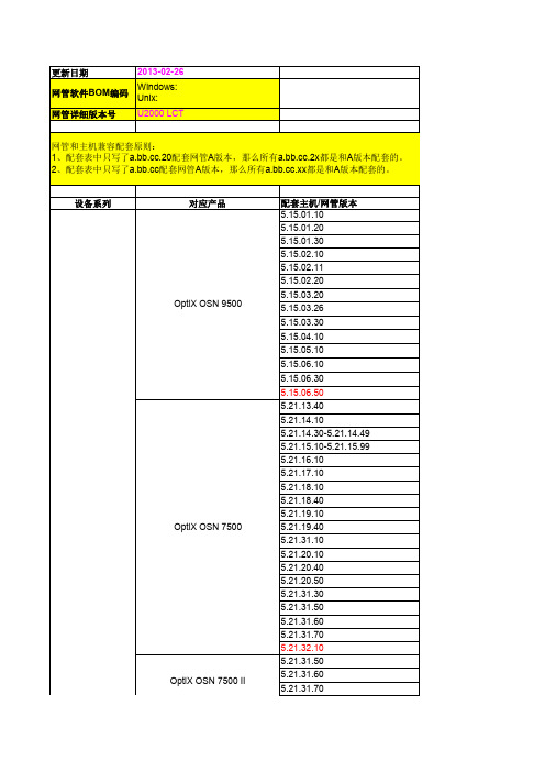
iManager U2000 LCT 产品版本配套表(传送域)-(V100R006C02SPC301_01)
OptiX 10G MADM(Me0
5.10.06.30
5.10.06.40
4.08.04.04
4.08.04.05 OptiX BWS 320G (OAS/OCI/OIS)
4.08.04.10
4.08.04.20
5.08.01.30
OptiX BWS 320GV3
5.39.02.10
5.39.02.20
Metro
OptiX Metro 6040V2 OptiX Metro 6100
OptiX Metro 6100V1
OptiX Metro 6100V1E Optix OSN 900A OptiX Metro 100 OptiX Metro 200 OptiX Metro 500
Metro
Marine DC
平台版本
OptiX Metro 1000V3
OptiX Metro 1050
OptiX Metro 1100
OptiX Metro 3100
OptiX BWS 1600S OptiX BWS 1600S T16
SLM 1630 PFE 1670 Data Center iMAP V3
OptiX OSN 1500
OptiX OSN 1500
OptiX OSN 2000 OptiX OSN 550 OptiX OSN 500 OptiX OSN 2500REG Optix PTN 1900
Optix PTN 3900
5.36.16.10 5.36.17.10 5.36.18.10 5.36.18.40 5.36.19.10 5.36.19.40 5.36.30.10 5.36.20.10 5.36.20.40 5.36.20.50 5.36.31.30 5.36.31.50 5.36.31.60 5.36.31.70 5.36.32.10 5.50.01.10 5.50.02.10 5.50.02.20 5.50.03.10 5.81.03.10 5.81.05.10 5.81.05.20 5.81.05.30 5.81.06.10 5.62.01.10 5.62.02.10 5.62.03.10 5.62.05.10 5.62.05.30 5.62.06.10 5.43.13.10 5.36.13.40 5.36.18.40 5.58.01.10 5.58.01.30 5.58.01.50 5.58.02.10 5.58.02.30 5.58.02.50 5.58.02.60 5.58.02.90 5.58.03.20 5.58.03.30 5.59.01.10 5.59.01.30 5.59.01.50 5.59.02.10
CommScope E6000 Converged Edge Router (CER) 产品介绍说

PRODUCT OVERVIEWThe E6000® Converged Edge Router (CER) is a next-generation Converged Cable Access Platform (CCAP ™) that provides cable operators unprecedented advances in channel density, power efficiency, and cost savings in a redundant, integratedarchitecture designed from the ground up for high availability. This powerful design allows operators to converge all services (video, high speed data, and voice), enabling additional savings in capital and operational expenditures along with increased operational efficiency. For Distributed Access Architecture (DAA) solutions, CommScope provides both the CCAP Core andRemote PHY (R-PHY) Device (RPD) defined in the CableLabs® Modular Headend Architecture (MHAv2). In this approach, the PHY layer is moved from the E6000 CER into a node or remote shelf, but the MAC processing, provisioning, and monitoring functions are performed by the E6000 CCAP Core.The Downstream CCAP Core Module (DCCM) has the same MAC processing capacity of the 2nd generation Downstream Cable Access Module (DCAM-2) but without the PHY-layer hardware and related components. The DCCM and DCAM-2 can be used interchangeably to provide downstream MAC processing for the E6000 CCAP Core. The DCCM offers power, weight, and cost savings over the DCAM-2 for Remote PHY applications. Without RF hardware, the DCCM cannot be used for I-CCAP applications. E6000 Release 7.0 and later support “hybrid” operation of Integrated CCAP (I-CCAP) and CCAP Core within the same chassis.Roadmap for future capabilities is subject to change.E6000® Converged Edge RouterDownstream CCAP Core ModuleThe Downstream CCAP Core Module (DCCM) isessentially a DCAM-2 without the RF circuitry. The DCCMis meant only for R-PHY operation for which it providesthe same functionality and capacity as the DCAM-2. TheDCCM and DCAM-2 are interchangeable for R-PHYoperation and can be mixed in the same E6000 chassis.The DCCM supports MAC processing for RPDs withdownstream RF bands up to 1.2 GHz. In addition, theDCCM can support multiple 192 MHz OFDM channelsper Service Group on capable RPDs. Operators receivesignificant benefits in terms of operational simplicity,power, and cost savings by deploying DCCM in R-PHYapplications. Use of DCCM requires the RSM-2 andeither UCAM-2 or UCCM upstream modules.Roadmap for future capabilities is subject to change.SUMMARY OF DCCM FEATURES AND CAPABILITIES (PARTIAL LIST)Downstream MAC Processing for Remote PHY Operation on the E6000 CER Acting as a CCAP CoreNo RF Output —R-PHY Operation OnlyFull Spectrum Capable (MAC processing for channels up to 1.2GHz)Interoperable with DCAM-2 in the Same E6000 ChassisMultiple DOCSIS 3.1 Downstream Channel Support (24 –192 MHz each) —Dependent on Software Release and RPD Capabilities DOCSIS 3.0 Downstream (Annex A and Annex B) Support —Channel Density Dependent on Software Release and RPD Capabilities Video SC-QAM Support for VOD and Broadcast Services —Channel Density Dependent on Software Release and RPD Capabilities Channel Density Scalability via Licensing or Software Upgrades (No Hardware Changes Required)E6000 CCAP Core Interoperable for Multi-Core R-PHY ArchitecturesDeploys with CCAP Core Rear Card (CCRC) –One Required on the Back of the E6000 Chassis for Each DCCMSPECIFICATIONSRemote PHY CapabilitiesFrequency Range (MHz)108 to 1218 (edge to edge)Modulation (QAM)All required by DOCSIS 3.0 and DOCSIS 3.1(Specific software support varies by release)Max OFDM Channel Width (MHz)192 (Multiple channels supported per RPD Service Group)Max SC-QAMs perDownstream Service Group128 (Sum total DOCSIS and IEQ)SC-QAM Data Rate (Mbps)(Max.)30.34 to 55.62 per channelMax Number of DS ServiceGroups per DCCM27SC-QAM RF Output Level(dBmV)Dependent on RPD PhysicalPower-48 VDCPower Consumption (W)135 (typical at 25 °C)Operating Temperature: Short Term °F (°C) Long Term °F (°C)+23 to +131 (-5 to +55) +41 to +104 (+5 to +40)Storage Temperature °F(°C)-40 to +158 (-40 to +70)Operating Humidity(Min.-Max.)5 to 85% (Non condensing)Dimensions(H x W x D) in. (cm)13.8 x 1.2 x 17. 8 (35.0 x 3.0 x 45.3) Weight lbs. (kg) Approx. 5 (2.3)SPECIFICATIONSInstallation Environment (System Level)Management Interfaces100/1000 Mbps Ethernet (RJ-45) plusConsole (serial port, RJ45)RF Connector Access NoneNSI Connector Access RSM-2 ports via front of chassis,RPIC-2Q ports via rear Management Access (System Level)In-band Management with Access Control Lists via any NSI portOut-of-Band Management via dedicated Ethernet port on RPIC-2Q Console (serial) port on RPIC-2QManaging the E6000® CER is typically done via SNMP and/or CLI. The E6000 CER has multiple options available for IPDR, a useful tool for measuring bandwidth usage. Physical maintenance of the E6000 CER is very simple. Air filters, one in the front and another in the rear of the chassis, should be inspected and/or replaced per recommendations in the E6000 CER User Guide.Roadmap for future capabilities is subject to change.Note:Specifications are subject to change without notice.Copyright Statement:©2021CommScope,Inc.All rights reserved.ARRIS,the ARRIS logo and E6000are trademarks of CommScope,Inc.and/or its affiliates.All other trademarks are the property of their respective owners.No part of this content may be reproduced in any form or by any means or used to make any derivative work (such as translation,transformation,or adaptation)without written permission from CommScope,Inc and/or its affiliates (“CommScope”).CommScope reserves the right to revise or change this content from time to time without obligation on the part of CommScope to provide notification of such revision or change.ORDERING CODES (PARTIAL LIST)Part NumberDescriptionPart NumberDescription1000536GEN-2 Duplex Chassis Kit -Two RSM-2s, No CAMs 1000325Router System Module 2 Kit -1 RSM-2 and RPIC-2Q 1000963CCRC -CCAP Core Rear Card (for DCCM and UCCM, active or spare)1001136SYSTEM-PRINCIPAL-CORE LICENSE1000961DCCM -DS CCAP Core Module (only for RPHYapplications; must purchase one of the Initial DS D3.0 MAC License Bundles with this item)1000962UCCM -US CCAP Core Module (only for RPHYapplications; must purchase one of the Initial Upstream D3.0 MAC License Bundles with this item)1000720E6000; 256 Initial DS D3.0 Annex A MAC License Bundle for DCAM-2 -For MAC Channels 1-256 (requires DCAM-2 HW purchase (PN 1000506) or DCCM HW purchase (PN 1000961))1000737E6000; 48 Initial Upstream D3.0 MAC License Bundle for UCAM-2 -For MAC Channels 1-48 (requires UCAM-2 HW purchase (PN 1000445) or UCCM HW purchase (PN 1000962))1000721E6000; 384 Initial DS D3.0 Annex A MAC License Bundle for DCAM-2 -For MAC Channels 1-384 (requires DCAM-2 HW purchase (PN 1000506) or DCCM HW purchase (PN 1000961))1001047E6000; 64 Initial Upstream D3.0 MAC License Bundle for UCAM-2 -For MAC Channels 1-64 (requires UCAM-2 HW purchase (PN 1000445) or UCCM HW purchase (PN 1000962))1001279E6000; 448 Initial DS D3.0 Annex A MAC License Bundle for DCAM-2 -For MAC Channels 1-448 (requires DCAM-2 HW purchase (PN 1000506) or DCCM HW purchase (PN 1000961))1000738E6000; 72 Initial Upstream D3.0 MAC License Bundle for UCAM-2 -For MAC Channels 1-72 (requires UCAM-2 HW purchase (PN 1000445) or UCCM HW purchase (PN 1000962))1000722E6000; 512 Initial DS D3.0 Annex A MAC License Bundle for DCAM-2 -For MAC Channels 1-512 (requires DCAM-2 HW purchase (PN 1000506) or DCCM HW purchase (PN 1000961))1000739E6000; 96 Initial Upstream D3.0 MAC License Bundle for UCAM-2 -For MAC Channels 1-96 (requires UCAM-2 HW purchase (PN 1000445) or UCCM HW purchase (PN 1000962))1000730E6000; 256 Initial DS D3.0 Annex B MAC License Bundle for DCAM-2 -For MAC Channels 1-256 (requires DCAM-2 HW purchase (PN 1000506) or DCCM HW purchase (PN 1000961))1000740E6000; 144 Initial Upstream D3.0 MAC License Bundle for UCAM-2 -For MAC Channels 1-144 (requires UCAM-2 HW purchase (PN 1000445) or UCCM HW purchase (PN 1000962))1000731E6000; 384 Initial DS D3.0 Annex B MAC License Bundle for DCAM-2 -For MAC Channels 1-384 (requires DCAM-2 HW purchase (PN 1000506) or DCCM HW purchase (PN 1000961))1000741E6000; 192 Initial Upstream D3.0 MAC License Bundle for UCAM-2 -For MAC Channels 1-192 (requires UCAM-2 HW purchase (PN 1000445) or UCCM HW purchase (PN 1000962))1001272E6000; 448 Initial DS D3.0 Annex B MAC License Bundle for DCAM-2 -For MAC Channels 1-448 (requires DCAM-2 HW purchase (PN 1000506) or DCCM HW purchase (PN 1000961))1000742E6000; 216 Initial Upstream D3.0 MAC License Bundle for UCAM-2 -For MAC Channels 1-216 (requires UCAM-2 HW purchase (PN 1000445) or UCCM HW purchase (PN 1000962))1000732E6000; 512 Initial DS D3.0 Annex B MAC License Bundle for DCAM-2 -For MAC Channels 1-512 (requires DCAM-2 HW purchase (PN 1000506) or DCCM HW purchase (PN 1000961))1000715E6000 D3.0 Downstream Annex A MAC Processing License (per 8 MHz D3.0 DS channel)1000736E6000 D3.0 Upstream MAC Processing License (per D3.0 US channel)1000716E6000 D3.0 Downstream Annex B MAC Processing License (per 6 MHz D3.0 DS channel)1000743E6000 D3.1 Downstream MAC Processing License (per 1 MHz channel)1000744E6000 D3.1 Upstream MAC Processing License (per 1 MHz channel)Full Price List available from CommScopeCUSTOMER CAREContact Customer Care for product information and sales:•United States: 866-36-ARRIS •International: +1-678-473-5656(rev 04-2021)E6000_CER_DCCM v1.0。
N32G031 系列勘误手册 V1.1说明书

N32G031系列勘误手册V1.1目录1勘误列表 (1)2复位和时钟控制(RCC) (2)LSE受相邻管脚翻转干扰 (2)3GPIO和AFIO (3)GPIO模拟功能 (3)IO倒灌电流 (3)4模拟/数字转换(ADC) (3)ADC注入通道触发规则通道转换 (3)5串行外设接口(SPI) (4)SPI接口 (4)5.1.1SPI波特率设置 (4)5.1.2从模式CRC校验 (4)I2S接口 (4)5.2.1PCM长帧模式 (4)6I2C接口 (5)当前字节传输前必须被管理的软件事件 (5)单次读取单字节时的注意事项 (5)7通用同步异步接收器(USART) (6)校验错误标志 (6)RTS硬件流控 (6)8定时器(TIM) (7)定时器重复捕获检测 (7)高级定时器与通用定时器在特定情况下无法产生比较事件 (7)9实时时钟(RTC) (8)RTC亚秒匹配 (8)RTC秒匹配 (8)RTC日历功能不能在1秒内多次初始化 (8)10芯片丝印及版本说明 (9)I11版本历史 (9)12声明 (10)II1勘误列表表 1-1勘误概述2复位和时钟控制(RCC)LSE受相邻管脚翻转干扰描述当LSE相邻管脚翻转时,会对LSE时钟频率产生影响。
解决方法避免LSE相邻管脚翻转3GPIO和AFIOGPIO模拟功能描述PA1/PA2/PA3/PA4这4个GPIO在输出高电平状态下,切换成模拟功能时,在切换过程中会短暂出现输出电压有30mv左右的压降。
解决方法避免上述使用方法。
IO倒灌电流描述不支持failsafe的IO如果先于VDD上电,此时有可能出现异常,出现异常后外部管脚复位无法恢复正常。
解决办法建议客户使用时VDD的上电优先于IO上电。
4模拟/数字转换(ADC)ADC注入通道触发规则通道转换描述ADC连续转换,规则通道外部触发不使能,软件或硬件触发注入通道转换时,规则通道可能会被启动转换,规则通道转换相应的状态位会置起。
THPFPS-1型实训指导书(含使用说明书)
目录第一章概述 (1)第二章实训项目 (9)PLC基本技能实操 (9)实训一 PLC认知实训 (9)实训二数码显示控制 (13)实训三抢答器控制 (15)实训四音乐喷泉控制 (18)实训五装配流水线控制 (20)实训六十字路口交通灯控制 (23)实训七水塔水位控制 (26)实训八天塔之光控制 (29)实训九多种液体混合装置控制 (32)实训十加工中心控制 (35)实训十一变频器功能参数设置与操作 (39)实训十二外部开关控制变频调速正反转 (46)实训十三外部模拟量(电压/电流)方式的变频调速控制 (48)实训十四基于PLC控制变频器的多段速运行 (49)附录使用说明书 (52)第一章概述一、PLC的分类及特点可编程控制器简称PLC(Programmable Logic Controller),在1987年国际电工委员会(International Electrical Committee)颁布的PLC标准草案中对PLC做了如下定义:PLC 是一种专门为在工业环境下应用而设计的数字运算操作的电子装置。
它采用可以编制程序的存储器,用来在其内部存储执行逻辑运算、顺序运算、计时、计数和算术运算等操作的指令,并能通过数字式或模拟式的输入和输出,控制各种类型的机械或生产过程。
PLC及其有关的外围设备都应该按易于与工业控制系统形成一个整体,易于扩展其功能的原则而设计。
(一) PLC的分类按产地分,可分为日系、欧美、韩台、大陆等。
其中日系具有代表性的为松下、三菱、欧姆龙、光洋等;欧美系列具有代表性的为西门子、A-B、通用电气、德州仪表等;韩台系列具有代表性的为LG、台达等;大陆系列具有代表性的为合利时、浙江中控等;按点数分,可分为大型机、中型机及小型机等。
大型机一般I/O点数>2048点,具有多CPU,16位/32位处理器,用户存储器容量8~16K;中型机一般I/O点数为256~2048点,单/双CPU,用户存储器容量2~8K;小型机一般I/O点数<256点,单CPU,8位或16位处理器,用户存储器容量4K字以下。
科远设备级驱动和自定义模块说明(新)

设备级驱动和自定义模块说明编制:黄轶青审核:曹瑞峰梅建华批准:刘国耀南京科远控制工程有限公司NANJING KEYUAN CONTROL ENGNEERING CO., LTD2003年11月目录1.不可调电动门(ACT15A3W:TVL_BT): (6)1.1模块原理 (6)1.2主要特性有: (6)1.3工作模式:(优先权由高到低) (8)1.4模块参数: (8)1.5不可调电动门在逻辑图中的表达方法如下例: (11)1.6如何组态参照组态演示文件. (11)2.点动门(ACT15A3W:TVL_DD): (13)2.1模块原理 (13)2.2主要特性有: (13)2.3工作模式:(优先权由高到低) (15)2.4模块参数: (15)2.5点动门在逻辑图中的表达方法如下例: (16)2.6如何组态参照组态演示文件. (16)3. 全开全关执行机构(ACT15A3W:TVL_AN): (17)3.1模块原理 (17)3.2模块参数: (17)3.3全开全关执行机构在逻辑图中的表达方法如下例: (18)3.4如何组态参照组态演示文件. (18)4.单位式设备(ACT15A3W:TVL_RS): (19)4.1模块功能 (19)4.2模块参数: (20)4.3单位式设备在逻辑图中的表达方法如下例: (20)4.4如何组态参照组态演示文件. (21)5.标准电机(ACT15A3W:TMT_ST): (21)5.1模块功能 (21)5.2主要特性有: (21)5.3工作模式:(优先权由高到低) (23)5.4模块参数: (23)5.5标准电机在逻辑图中的表达方法如下例: (24)5.6如何组态参照组态演示文件. (25)6.一带八设备模块(DIGACT:TCKGF8A): (26)6.1模块功能: (26)6.2主要特性有: (26)6.3模块参数: (26)6.4一带八设备模块在逻辑图中的表达方法 (27)6.5如何组态参照组态演示文件. (28)7.多功能软伺放(ACT15A3W:ANMMF): (29)7.1模块功能 (29)7.4模块参数: (31)7.5模块选型: (35)7.6如何组态参照组态演示文件. (35)8.四回路多输出T2500软伺放(ACTION:AMF): (36)8.1模块功能 (36)8.2主要特性有: (36)8.3工作模式: (37)8.4模块参数: (38)8.5模块选型: (39)8.6四回路多输出T2500软伺放在逻辑图中的表达方法 (40)8.7如何组态参照组态演示文件. (40)9.模拟量手操模块(ACTION:MANS): (42)9.1模块功能 (42)9.2主要特性有: (42)9.3工作模式: (43)9.4模块参数: (44)9.5模拟量手操站在逻辑图中的表达方法 (46)9.6如何组态参照组态演示文件. (46)10.二值优选模块(ACTION:OF2VOTE(FILENAME和ACTNAME)): (48)10.1模块功能 (48)10.2参数 (48)10.3二值优选模块在逻辑图中的表达方法如下例: (49)10.4如何组态参照组态演示文件. (49)11.自动冗余切换、故障集合及负荷率运算模块(ACTION:DIAG(FILENAME和ACTNAME)): 5011.1模块功能 (50)11.2模块参数 (50)11.3如何组态参照组态演示文件. (50)12.十一回路首出原因模块(ACT15A3W:ETSST(FILENAME和ACTNAME)): (51)12.1模块功能 (51)12.2模块参数 (51)12.3在逻辑图中的表达方法 (51)12.4如何组态参照组态演示文件. (51)13.串级回路抗积分饱和模块(ACTION:SERCO (FILENAME和ACTNAME)): (52)13.1块功能说明 (52)13.2参数 (52)13.3在逻辑图中的表达方法 (52)13.4如何组态参照组态演示文件. (52)14.两前馈协调模块(ACTION:NODISTB(FILENAME和ACTNAME)): (53)14.1模块原理该 (53)14.4如何组态参照组态演示文件. (53)15.过热蒸汽流量补偿(ACTION:MATH(FILENAME)FL_OVER(ACTNAME)): (54)15.1模块原理 (54)15.2参数 (54)15.3如何组态参照组态演示文件. (54)16.汽包水位补偿模块(ACTION:MATH(FILENAME)DLEL(ACTNAME)): (55)16.1模块原理 (55)16.2参数 (55)16.3如何组态参照组态演示文件. (55)17.积分处理模块(ACTION:INTGDW32(FILENAME和ACTNAME)): (56)17.1模块功能 (56)17.2参数 (56)17.3在逻辑图中的表达方法 (56)17.4如何组态参照组态演示文件. (56)18.一带八同操处理模块(ACTION:TCON(FILENAME和ACTNAME) (57)18.1模块功能 (57)18.2参数 (57)18.3在逻辑图中的表达方法 (58)18.4如何组态参照组态演示文件. (58)19.一带十二同操+一带四同操处理(ACT15A3W:TCON3W(FILENAME和ACTNAME)) (59)19.1模块功能 (59)19.2参数 (59)19.3在逻辑图中的表达方法 (60)19.4如何组态参照组态演示文件. (60)20.八路电量脉冲累积模块(ACTION:PLSTAT(FILENAME) STAT8(ACTNAME)) (61)20.1模块功能 (61)20.2参数 (61)20.3在逻辑图中的表达方法 (61)20.4如何组态参照组态演示文件. (61)21.机炉协调控制模块(ACT15A3W:LMCC(FILENAME和ACTNAME)): (62)21.1模块功能 (62)21.2模块参数 (62)21.3如何组态参照组态演示文件. (63)22.单元机组煤粉炉燃料控制模块 (64)22.1模块功能 (64)22.2模块参数 (64)22.3如何组态参照组态演示文件. (65)23.2参数 (66)23.3在逻辑图中的表达方法 (67)23.4如何组态参照组态演示文件. (67)24.MFT控制模块(DIGACT:ACT15A3W(FILENAME) MFT(ACTNAME)) (68)24.1模块功能 (68)24.2参数 (68)24.3在逻辑图中的表达方法 (69)24.4如何组态参照组态演示文件. (69)25.数字量三取二模块(ACTION:ACTION(FILENAME) LOGIC2_3(ACTNAME)) (70)25.1模块功能 (70)25.2参数 (70)25.3在逻辑图中的表达方法 (70)25.4如何组态参照组态演示文件. (70)26.数字量四取二模块(ACTION:ACTION(FILENAME) LOGIC2_4(ACTNAME)) (71)26.1模块功能 (71)26.2参数 (71)26.3在逻辑图中的表达方法 (71)26.4如何组态参照组态演示文件. (71)27.数字量四取三模块(ACTION:ACTION(FILENAME) LOGIC3_4(ACTNAME)) (72)27.1模块功能 (72)27.2参数 (72)27.3在逻辑图中的表达方法 (72)27.4如何组态参照组态演示文件. (72)28.数字量六取四模块(ACT15A3W:LOGMUL(FILENAME) LOGIC4_6(ACTNAME)) (73)28.1模块功能 (73)28.2参数 (73)28.3在逻辑图中的表达方法 (73)28.4如何组态参照组态演示文件. (73)29.数字量八取六模块(ACTION:LOGMUL(FILENAME) LOGIC6_8(ACTNAME)) (74)29.1模块功能 (74)29.2参数 (74)29.3在逻辑图中的表达方法 (74)29.4如何组态参照组态演示文件. (74)30.脉冲发生模块(DIGACT:PULSE(FILENAME) PULSE(ACTNAME)) (75)30.1模块功能 (75)30.2参数 (75)30.3在逻辑图中的表达方法 (75)30.4如何组态参照组态演示文件. (75)31.1.1开关型集成设备级模块的分类 (76)31.1.2.模拟量集成设备级模块的分类 (76)31.2MMI设备级连接 (78)31.2.1可调电动门(图标Dynamos名:NKTKGICO,面板Dynamos名:NKTVL_BT) (78)31.2.2点动式电动门(图标Dynamos名:NKTKGICO,面板Dynamos名:NKTVL_DD) (82)31.2.3全开全关执行机构(图标Dynamos名:NKTKGICO,面板Dynamos名:NKTVL_AN) (83)31.2.4电动机与泵(图标Dynamos名:NKTKGICO,面板Dynamos名:NKTMT_ST) (84)31.2.5断路器(图标Dynamos名:NKTKGICO,面板Dynamos名:NKTMT_DL) (85)31.2.6单位式设备(图标Dynamos名:NKTKGICO,面板Dynamos名:NKTVL_RS) (86)31.2.7双线圈电磁阀(图标Dynamos名:NKTKGICO,面板Dynamos名:NKTVL_RS) (87)31.2.8调整门1:单PID调节,并且现场设备的接口为AO (88)31.2.9调整门2:单PID调节,并且现场设备的接口为PO (90)31.2.10调整门3:串级PID调节,并且与现场设备的接口为AO (91)31.2.11调整门4:无PID调节,纯手动操作设备,与现场设备的接口为AO (91)32.附录 (93)1.不可调电动门(ACT15A3W:TVL_BT):1.1模块原理Fig. 1.1 不可调电动门模块的逻辑图请参看图1.1,该设备模块用于驱动一个不可调整型电动门,接收从现场设备来的“已开和已关信号”,根据逻辑判断发出DO信号控制现场电动门全开或全关。
雅特力 AT32F403A AT32F407入门使用指南说明书
AN0023应用笔记AT32F403A & AT32F407入门使用指南前言本应用入门指南旨在让用户快速使用AT32F403Axx /AT32F407xx进行项目开发,AT32F407 相较于AT32F403A 增加了以太网(EMAC)功能。
注:本应用笔记对应的代码是基于雅特力提供的V2.x.x 板级支持包(BSP)而开发,对于其他版本BSP,需要注意使用上的区别。
目录雅特力初步环境准备 (6)调试工具及开发板 (6)烧录工具及软件 (6)AT32开发环境 (7)快速替代SXX流程 (12)AT32F403A /AT32F407芯片的增强功能配置 (13)PLL时钟设置 (13)如何打开FPU功能(硬件浮点运算单元) (15)AT32F403A /AT32F407 零等待/非零等待Flash和内置SRAM大小选择配置说明 .. 16加密方式(访问保护,擦写保护,外部Flash加密) (21)在程序中区分AT32与其他IC方法 (25)下载编译过程常见问题 (28)Keil项目内Jlink无法找到IC (28)程序下载过程出问题 (28)显示Error: Flash Download failed–“Cortex-M4”问题 (28)显示No Debug Unit Device found 问题 (29)显示RDDI-DAP Error 问题 (29)ISP串口下载时卡死问题 (29)AT32恢复下载 (29)安全库区sLib(Security Library) (32)应用原理 (32)操作安全库区 (32)文档版本历史 (33)表1. 文档版本历史 (33)图1. AT-START-F407开发板及AT-Link-EZ实物图 (6)图2. 雅特力科技官方网站AT-START-F407开发板资料包 (6)图3. 雅特力科技官方网站ICP/ISP/AT-Link-Family资料包 (7)图4. 雅特力科技官方网站BSP资料包 (7)图5. Keil_v5 templates工程示例 (8)图6. 雅特力科技官方网站Pack包 (8)图7. 安装ArteryTek.AT32F403A_407_DFP (9)图8. 安装Keil4_AT32MCU_AddOn (9)图9. Keil中Pack Installer图标 (9)图10. 安装IAR_AT32MCU_AddOn (10)图11. Keil Debug选项 (10)图12. Keil Debug选项Settings设置 (11)图13. Keil Utilities选项 (11)图14. IAR Debug选项 (11)图15. IAR CMSIS-DAP选项 (12)图16. SXX程序在AT32F403A /AT32F407输出240MHz的时钟配置 (13)图17. AT32F403A /AT32F407 crm_pll_output_range参数 (13)图18. 雅特力科技官方网站时钟配置工具 (14)图19. SXX程序PLL自动滑顺频率切换配置 (14)图20. AT32程序PLL自动滑顺频率切换配置 (14)图21. Keil环境中选择开启FPU (15)图22. Keil环境中增加开启FPU的代码 (15)图23. IAR环境中选择开启FPU (16)图24. IAR环境中增加开启FPU的代码 (16)图25. ICP工具编辑用户系统数据选择SRAM大小 (17)图26. 用户系统数据设置选择SRAM大小 (18)图27. ISP 工具编辑用户系统数据选择SRAM大小 (18)图28. ISP Multi-Port Programmer工具用户系统数据设置 (19)图29. SXX程序定义Extend_SRAM(void)函数 (19)图30. AT32程序定义Extend_SRAM(void)函数 (20)图31. Keil启动文件中修改SRAM大小 (20)图32. IAR启动文件中修改SRAM大小 (21)图33. ISP工具启用访问保护 (22)图34. ISP工具解除访问保护 (22)图35. ICP工具启用擦写保护 (23)图36. ICP工具解除擦写保护 (24)图37. ICP工具对外部存储器加密操作 (25)图38. ISP工具对外部存储器加密操作 (25)图39. 读取Cortex型号 (26)图40. 读取UID,PID (26)图41. 增加开启FPU的代码 (28)图42. 下载出现Flash Download failed–“Cortex- M4” (28)图43. KEIL环境中工具ConfigJLink_V1.0.0的操作 (30)图44. KEIL环境中工具ConfigJLink_V1.0.0执行过程 (30)图45. IAR环境中工具ConfigJLink_V1.0.0的操作 (31)图46. IAR环境中工具ConfigJLink_V1.0.0执行过程 (31)雅特力初步环境准备雅特力开发环境下载地址:⏹雅特力科技官方网站:搭建AT32开发环境调试工具及开发板目前AT32F403A /AT32F407开发板都自带AT-Link-EZ调试工具,AT-Link-EZ如下图左边红框所示,它也可拆开后单独搭配其他电路板使用,支持IDE在线调试、在线烧录、USB转串口等功能。
M16B开发板实验指导书v1.0

安全需知
为防止损坏您的 AVR 相关工具,避免您或他人受伤,在使用本开发套装前请仔细阅读下面 的安全需知,并妥善保管以便所有本产品设备的使用者都可随时参阅。
请遵守本节中所列举的用以下符号所标注的各项预防措施,否则可能对产品造成损害。
该标记表示警告,提醒您应该在使用本产品前阅读 这些信息,以防止可能发生的损害。
警告
请勿在易燃气体环境中使用电子设备,以避免发生爆炸或火灾。 请勿在潮湿的环境中使用电子设备,以避免设备损坏。 发生故障时立即拔下所有线缆。 当您发现产品冒烟或发生异味时,请立刻拔下所有与其连接的线缆,切断电源,以避 免燃烧。若在这种情况下还继续使用,可能会导致产品的进一步损坏,并使您受伤。 请与我们联系后,将产品寄回给我们维修。 请勿自行拆卸本产品 触动产品内部的零件可能会导致受伤。 遇到故障时,请及时联系我们。 自行拆卸可能会导致其他意外事故发生。 使用合适的电缆线 若要将线缆连接到本设备的插座上,请使用本产品提供的线缆,以保证产品的规格的 兼容性。 请勿在儿童伸手可及之处保管本产品 请特别注意防止婴幼儿玩耍或将产品的小部件放入口中。
M16B 开 发 板 实验指导书
V1.0 – 2008-10-29
本资料由北京百纳信达科技有限公司编写、版权所有 商标咨询 ATMEL 与 AVR 分别是 ATMEL CORPORATION 的注册商标和商标 百纳信达、、 分别是北京百纳信达科技有限公司的商标与域名
实验二 Mega16 IO 口作为输入使用 ................................................................................................... 3
【实验目的】 .............................................................................................................................................. 3 【实验设备】 .............................................................................................................................................. 3 【实验要求】 .............................................................................................................................................. 3 【实验原理】 .............................................................................................................................................. 3 【实验步骤】 .............................................................................................................................................. 4 【范例路径】 .............................................................................................................................................. 4 【思考练习】 .............................................................................................................................................. 5
C语言编译错误总结
非常实用的,吸收前辈的经验,我们才能少走弯路。
和C 编译器错误信息中文翻译(1)L15 重复调用***WARNING L15: MULTIPLE CALL TO SEGMENTSEGMENT: ?PR?SPI_RECEIVE_WORD?D_SPICALLER1: ?PR?VSYNC_INTERRUPT?MAINCALLER2: ?C_C51STARTUP该警告表示连接器发现有一个函数可能会被主函数和一个中断服务程序(或者调用中断服务程序的函数)同时调用,或者同时被多个中断服务程序调用。
出现这种问题的原因之一是这个函数是不可重入性函数,当该函数运行时它可能会被一个中断打断,从而使得结果发生变化并可能会引起一些变量形式的冲突(即引起函数内一些数据的丢失,可重入性函数在任何时候都可以被ISR 打断,一段时间后又可以运行,但是相应数据不会丢失)。
原因之二是用于局部变量和变量(暂且这样翻译,arguments,[自变量,变元一数值,用于确定程序或子程序的值])的内存区被其他函数的内存区所覆盖,如果该函数被中断,则它的内存区就会被使用,这将导致其他函数的内存冲突。
例如,第一个警告中函数WRITE_GMVLX1_REG 在D_GMVLX1.C 或者D_GMVLX1.A51 被定义,它被一个中断服务程序或者一个调用了中断服务程序的函数调用了,调用它的函数是VSYNC_INTERRUPT,在MAIN.C 中。
解决方法:如果你确定两个函数决不会在同一时间执行(该函数被主程序调用并且中断被禁止),并且该函数不占用内存(假设只使用寄存器),则你可以完全忽略这种警告。
如果该函数占用了内存,则应该使用连接器(linker)OVERLAY 指令将函数从覆盖分析(overlayanalysis)中除去,例如:OVERLAY (?PR?_WRITE_GMVLX1_REG?D_GMVLX1 ! *)上面的指令防止了该函数使用的内存区被其他函数覆盖。
ACKU040 核心板用户手册说明书

KINTEX UltraScale开发平台用户手册ACKU040核心板2 / 24芯驿电子科技(上海)有限公司文档版本控制文档版本修改内容记录REV1.0创建文档目录文档版本控制 (2)一、ACKU040核心板 (4)(一)简介 (4)(二)FPGA芯片 (5)(三)DDR4 DRAM (5)(四)QSPI Flash (10)(五)时钟配置 (11)(六)LED灯 (12)(七)电源 (12)(八)结构图 (14)(九)连接器管脚定义 (14)3 / 244 / 24芯驿电子科技(上海)有限公司一、 ACKU040核心板(一) 简介ACKU040(核心板型号,下同)核心板,FPGA 芯片是基于XILINX 公司的XC7K325系列的XCKU040-2FFVA1156I 。
核心板使用了4片Micron 的1GB 的DDR4芯片MT40A512M16LY-062EIT,总的容量达4GB 。
另外核心板上也集成了2片128MBit 大小的QSPI FLASH ,用于启动存储配置和系统文件。
这款核心板的6个板对板连接器扩展出了359个IO ,其中BANK64和BANK65的104个IO 的电平是3.3V ,其它BANK 的IO 都是1.8V 。
另外核心板也扩展出了20对高速收发器GTH 接口。
对于需要大量IO 的用户,此核心板将是不错的选择。
而且IO连接部分,FPGA 芯片到接口之间走线做了等长和差分处理,并且核心板尺寸仅为80*60(mm ),对于二次开发来说,非常适合。
ACKU040核心板正面图5 / 24(二) FPGA 芯片核心板使用的是Xilinx 公司的KINTEX UltraSacale 芯片,型号为XCKU040-2FFVA1156I 。
速度等级为2,温度等级为工业级。
此型号为FFVA1156封装,1156个引脚,引脚间距为1.0mm 。
Xilinx KINTEX UltraSacale 的芯片命名规则如下图1-2-1所示:图1-2-1 KINTEX UltraSacale FPGA 型号命名规则定义其中FPGA 芯片XCKU040的主要参数如下所示:名称具体参数 逻辑单元Logic Cells 530,250 查找表(CLB LUTs) 242,400 触发器(CLB flip-flops) 484,800 Block RAM (Mb )大小 21.1 DSP 处理单元(DSP Slices )1,920 PCIe Gen3 x8 3GTH Transceiver20个,16.3Gb/s max速度等级 -2 温度等级工业级(三) DDR4 DRAM核心板上配有四片Micron(美光)的1GB 的DDR4芯片,型号为MT40A512M16LY-062EIT 。
EtherCAT I O 从站 E20P1-Y01 用户手册说明书
EtherCAT I/O从站E20P1-Y01用户手册V1.1成都乐创自动化技术股份有限公司修订记录目录前言 (5)安全使用注意事项 (5)安全要点 (8)版本信息 (10)术语 (11)1. 功能与系统构成 (12)1.1. I/O单元的特点与类型 (12)1.1.1. I/O单元的功能 (12)1.1.2. I/O单元类型 (12)1.2. 系统构成与从站单元 (12)1.2.1. 概述 (12)1.2.2. 系统构成 (13)1.3. 型号列表 (14)1.3.1. 型号表示方法 (14)1.3.2. 脉冲单元 (15)1.4. 功能列表 (15)1.4.1. 脉冲单元 (15)2. 产品规格 (17)2.1. 通用规格 (17)2.2. 特殊规格 (17)3. 部件名称与功能 (17)3.1. 部件名称 (18)3.1.1. 连接器类型 (18)3.2. 指示 (19)3.2.1. 单元工作状态指示 (19)3.2.2. IN/OUT指示灯 (19)4. 安装与接线 (20)4.1. 安装E系列单元 (20)4.1.1. 安装至柜内 (20)4.1.2. E系列单元的安装 (23)4.1.3. 卸下E系列单元 (24)4.1.4. 组装时的外观和尺寸 (26)4.2. 接线方法 (27)4.2.1. 单元电源的接线 (27)4.2.2. I/O信号的接线—输入单元 (28)4.2.3. I/O信号的接线—输出单元 (32)4.2.4. I/O信号的接线—脉冲单元 (33)5. I/O刷新 (35)5.1. 从站单元的I/O刷新 (35)5.1.1. 从控制器到从站单元的I/O刷新 (35)5.2. I/O刷新模式 (35)5.2.1. I/O刷新模式的类型 (35)5.2.2. 设置I/O刷新方法 (35)5.2.3. 选择E系列单元 (36)5.2.4. Free-Run模式刷新 (36)5.2.5. SM模式刷新 (37)5.2.6. DC模式刷新 (38)6. 脉冲单元 (40)6.1. 脉冲单元类型 (40)6.2. 设置列表 (40)6.2.1. I/O接口 (40)6.2.2. 对输入口X9~X16的说明 (41)6.2.3. 指示灯接口 (41)6.2.4. PDO数据映射 (43)6.3. 配置文件及操作 (48)7. 维护检查 (51)7.1. 清扫和检查 (51)7.1.1. 清扫方法 (51)7.1.2. 定期检查 (51)7.2. 维护程序 (52)A 附录 (53)A-1 数据手册 (53)A-1-1 型号列表 (53)A-1-2 脉冲单元 (54)A-2 外形尺寸图 (58)前言安全使用注意事项安全使用的标示和含义本手册中以下列标示和图形符号表示安全使用E系列从站单元的注意事项。
OptiX iManager T2000 V100R008C02 CORBA 接口技术手册

华为 OptiX iManager T2000 V100R008C02 CORBA接口技术手册华为技术有限公司版权所有侵权必究修订记录目录1系统概述 (9)1.1iManager T2000子网模型CORBA接口的背景 (9)1.2iManager T2000子网模型CORBA接口遵从的标准 (9)1.3iManager T2000子网模型CORBA接口的实现技术要点 (10)1.4iManager T2000子网模型CORBA接口在综合网管中的地位 (10)2接口功能 (11)2.1功能概述 (11)2.2配置管理 (12)2.2.1存量获取 (12)2.2.2通知上报 (15)2.3连接管理(Connection Management) (16)2.3.1创建子网连接 (16)2.3.2激活子网连接 (17)2.3.3创建并激活子网连接 (17)2.3.4去激活子网连接 (18)2.3.5删除子网连接 (18)2.3.6去激活并删除子网连接 (18)2.3.7验证创建子网连接的可行性 (18)2.4故障管理(Fault Management) (18)2.5保护管理(Protection Management) (19)2.6性能管理(Performance Management) (19)2.6.1PM数据收集的使能/禁止 (19)2.6.2支持PM寄存器clear/reset (20)2.6.3PM能力 (20)2.6.4门限设置 (20)2.6.5越限告警通知 (20)2.6.6门限查询 (20)2.6.7历史PM数据 (20)2.6.8当前PM数据查询 (20)2.7设备管理(Equipment Management) (21)2.7.1获取设备信息 (21)2.7.2获取设备支持的终结点 (21)2.7.3单板的创建和删除 (21)2.8维护命令(Maintenance Operation) (21)2.9安全管理(Security Management) (22)2.9.1安全验证 (22)2.9.2session管理 (22)2.9.3NMS-EMS通信状态监视 (22)2.10界面直通(GUI Cut-Through) (22)2.11异常管理(Exception Management) (23)2.12说明 (23)3.1.1.数据类型描述模板 (23)3.1.2.操作描述模板 (24)3.1.3.异常说明 (24)3.1.4.标识符说明 (25)3.1.5.通用Iterator对象 (25)mon模块 (26)3.2.1.数据类型 (26)3.2.2.接口 (26)3.2.3.通知 (26)3.3.EmsMgr模块 (27)3.3.1.数据类型 (27)3.3.2.接口 (27)3.3.3.通知 (28)3.4.Ems Session模块 (28)3.4.1.数据类型 (28)3.4.2.接口 (28)3.4.3.通知 (28)3.5.EmsSessionFactory (29)3.5.1.数据类型 (29)3.5.2.接口 (29)3.5.3.通知 (29)3.6.Equipment模块 (29)3.6.1.数据类型 (29)3.6.2.接口 (30)3.6.3.通知 (31)3.7.GuiCutThrough模块 (32)3.7.1.数据类型 (32)3.7.2.接口 (32)3.7.3.通知 (32)3.8.MaintenanceOperations模块 (33)3.8.1.数据类型 (33)3.8.2.接口 (33)3.8.3.通知 (34)3.9.Managed Element模块 (34)3.9.1.数据类型 (34)3.9.2.接口 (34)3.9.3.通知 (34)3.10. ManagedElementMgr模块 (35)3.10.1.数据类型 (35)3.10.2.接口 (35)3.10.3.通知 (36)3.11. MTNM Version模块 (37)3.11.1.数据类型 (37)3.11.2.接口 (37)3.11.3.通知 (37)3.12. MultiLayerSubnetwork模块 (37)3.12.1.数据类型 (37)3.12.2.接口 (37)3.12.3.通知 (40)3.13. Performance模块 (40)3.13.1.数据类型 (40)3.13.2.接口 (41)3.13.3.通知 (42)3.14. Protection模块 (42)3.14.1.数据类型 (42)3.14.2.接口 (42)3.14.3.通知 (43)3.15. Session模块 (44)3.15.1.数据类型 (44)3.15.2.接口 (44)3.15.3.通知 (44)3.16. Subnetwork Connection模块 (44)3.16.1.数据类型 (44)3.16.2.接口 (45)3.16.3.通知 (45)3.17. Termination Point模块 (45)3.17.1.数据类型 (45)3.17.2.接口 (46)3.17.3.通知 (46)3.18. Topological Link模块 (46)3.18.1.数据类型 (46)3.18.2.接口 (47)3.18.3.通知 (47)3.19. CORBA相关规范 (47)3.19.1.CORBA以及CORBA Service规范的版本支持情况 (47)3.19.2.Notification Service的支持情况 (47)3名字服务 (48)4对象命名规则 (49)4.1EMS (49)4.2Subnetwork (50)4.3SubnetworkConnection (50)4.4ManagedElement (50)4.5TopologicalLink (50)4.6PTP (51)4.7CTP (51)4.8TPPool (52)4.9TrafficDescriptor (52)4.10EquipmentHolder (52)4.11Equipment (53)4.12ProtectionGroup (53)4.13Other Objects (for Alarm purposes) (53)关键词:摘要:缩略语清单:无。
- 1、下载文档前请自行甄别文档内容的完整性,平台不提供额外的编辑、内容补充、找答案等附加服务。
- 2、"仅部分预览"的文档,不可在线预览部分如存在完整性等问题,可反馈申请退款(可完整预览的文档不适用该条件!)。
- 3、如文档侵犯您的权益,请联系客服反馈,我们会尽快为您处理(人工客服工作时间:9:00-18:30)。
配置SVI示例
Switch#configure terminal Switch(config)#vlan 10 Switch(config-vlan)exit Switch(config)#vlan 20 Switch(config-vlan)#exit Switch(config)#interface vlan 10 Switch(config-if)#ip address 192.168.1.1 255.255.255.0 Switch(config-if)#no shutdown Switch(config)#interface vlan 20 Switch(config-if)#ip address 192.168.2.1 255.255.255.0 Switch(config-if)#no shutdown
步骤1:进入端口配置模式
Swtich(config)#interface interface
步骤2:将端口模式设置为接入端口
Switch(config-if)#switchport mode access
步骤3:将端口添加到特定VLAN
Switch(config-if)#switchport access vlan vlan-id
配置SVI
步骤1 开启路由功能(默认)
Switch(config)#ip routing
步骤2 创建VLAN
Switch(config)#vlan vlan-id
步骤3 进入VLAN的SVI接口配置模式
Switch(config)#interface vlan vlan-id
步骤4 给SVI接口配置IP地址
Enabled 1,3-4094
Switch# show vlan
VLAN Name ---1 -------default Status -------active Ports
--------------Fa0/1, Fa0/2, Fa0/3, Fa0/4,
课程议题
SVI实现VLAN间通信
划分VLAN的问题
配置VLAN——将端口加入VLAN
示例:将端口FastEthernet 0/1加入VLAN
Switch#configure terminal Switch(config)#interface fastEthernet 0/1 Switch(config-if)#switchport mode access Switch(config-if)#switchport access vlan 10 Switch(config-if)#end
VLAN是划分出来的逻辑网络,是第二层网络。 VLAN端口不受物理位置的限制。 VLAN 隔离广播域。
VLAN技术的好处
通过在交换网络中的VLAN技术的实施,可以为网络带来很多诸如 隔离广播、安全、负载分担等好处。
隔离广播:在交换网络中,通过广播域的隔离,可以大大减少网络中泛 洪的广播包,从而提高网络中的带宽利用率。 安全性:通过在二层网络划分VLAN,可以实现在二层网络中不同VLAN 间的数据隔离,。 故障隔离:通过VLAN的划分,由于将设备划分到不同的广播域当中,可 以减小网络故障的影响。
步骤2:为子接口封装802.1q协议,并指定接口所属的VLAN
Router(config-subif)#encapsulation dot1q vlan-id
步骤3:为子接口配置IP地址
Router(config-subif)#ip address ip-address mask-address
步骤4:启用子接口
VLAN配置——配置Trunk和Native VLAN
将级联端口设置为Trunk 步骤1:进入需要配置的端口
swtich(config)#interface interface
步骤2:将端口的模式设置为Trunk
Switch(config-if)#switchport mode trunk
配置Native VLAN 步骤1:进入到需要配置的Trunk端口中
步骤2:进入需要配置为Trunk的端口
Switch(config)#interface interface
步骤3:定义该端口模式为Trunk
Switch(config-range-if)#switchport mode trunk
步骤4:定义Trunk的VLAN列表
Switch(config-if)#switchport trunk allowed vlan { all | [ add | remove | except ] } vlan-list
Trunk端口工作原理
Tag标签 数据帧 数据帧
Trunk
Trunk
A
B
802.1Q工作特点:
Trunk上默认会转发交换机上存在的所有VLAN的数据。 交换机在从Trunk口转发数据前会在数据打上个Tag标签,在到达另一交 换机后,再剥去此标签。 Native VLAN:这类VLAN可以省略掉打标签的过程,但是网络中只能有 一个Native VLAN,默认情况下,锐捷交换机上的Native VLAN是VLAN 1。
IEEE802.1Q数据帧
标记协议标识(TPID):
固定值0x8100,表示该帧载有802.1Q标记信息
标记控制信息(TCI):
Priority:3比特,表示优先级 Canonical format indicator:1比特,表示总线型以太网、FDDI、令牌环网 VlanID:12比特,表示VID,范围1-4094
Pravite VLAN的组成
PVLAN可以将一个VLAN的二层广播域划分成多个子域,每个子域 都由一对VLAN组成:Primary VLAN(主VLAN)和Secondary VLAN(辅助VLAN组成)。
Primary VLAN F0/1 F0/2
Secondary VLAN
Secondary VLAN
Router(config-subif)#no shutdown
单臂路由配置示例
Router(config)#interface fastEthernet 0/0.1 Router(config-subif)#encapsulation dot1q 10 Router(config-subif)#ip address 192.168.1.1 255.255.255.0 Router(config-subif)#no shutdown Router(config-subif)#exit Router(config)#interface fastEthernet 0/0.2 Router(config-subif)#encapsulation dot1q 20 Router(config-subif)#ip address 192.168.2.1 255.255.255.0 Router(config-subif)#no shutdown Router(config-subif)#end
配置VLAN——将一组端口加入VLAN
步骤1:进入到一组需要添加到VLAN的端口中
Swtich(config)#interface range interface-range
步骤2:将端口模式设置为接入端口
Switch(config-range-if)#switchport mode access
课程议题
使用单臂路由 实现VLAN间通信
路由器实现VLAN间路由
在路由器上为每个VLAN划分一个子接口 每个子接口配置IP地址,作为相应VLAN的网关 利用路由器的路由功能,实现不同子接口数据的转发 缺点是:部署不灵活,形成网络瓶颈。
单臂路由配置
步骤1:创建以太网子接口
Router(config)#interface interface.sub-port
swtich(config)#interface interface
步骤2:配置Trunk的Native VLAN
Switch(config-if)#switchport trunk native vlan vlan-id
配置VLAN——配置VLAN许可列表
步骤1:进入全局配置模式
Switch#configure terminal
步骤3:将一组端口划分到指定VLAN
Switch(config-range-if)#swtichport access vlan vlan-id
配置VLAN——将一组端口加入VLAN
示例:将端口fastEthernet 0/1~5,0/7同时划分到VLAN10
Switch#configure terminal Switch(config)#interface range fastEthernet 0/1-5,0/7 Switch(config-if-range)#switchport mode access Switch(config-if-range)#switchport access vlan 10 Switch(config-if-range)#exit
Pravite VLAN的组成
主VLAN: 主VLAN是PVLAN的高级VLAN,每个PVLAN中只有一 个主VLAN。 辅助VLAN: 辅助VLAN是PVLAN中的子VLAN,并且映射到一个 主VLAN。每台接入设备都连接到辅助VLAN。
课程议题
VLAN配置
交换网络中的问题
广播域
在交换机组成的校园网络里所有主机都在同一个广播域内
交换网络中的问题
VLAN 20 VLAN 30
VLAN 40 VLAN 10
通过VLAN技术可以对网络进行一个安全的隔离、分割广播域
VLAN技术
交换机 1 2 3 4
