31-第三章cameralink相机接口3.1cameralink简介3.1.1LVDS技术简介 (2)
CameraLink接口数字相机图像显示装置解读ppt课件

“雪亮工程"是以区(县)、乡(镇) 、村( 社区) 三级综 治中心 为指挥 平台、 以综治 信息化 为支撑 、以网 格化管 理为基 础、以 公共安 全视频 监控联 网应用 为重点 的“群 众性治 安防控 工程” 。
VGA接口的结构
VGA接口是一种D型接口, 上面共有15针空,分成 三排,每排五个。 其中,
乒乓缓存介绍
当SDRAM1中缓存满了一帧图像数据后,开 始读取数据,读SDRAM1时写SDRAM2。当 SDRAM2中写满一帧图像数据后,控制器对 两个SDRAM进行读写切换,读SDRAM2时 写SDRAM1。
“雪亮工程"是以区(县)、乡(镇) 、村( 社区) 三级综 治中心 为指挥 平台、 以综治 信息化 为支撑 、以网 格化管 理为基 础、以 公共安 全视频 监控联 网应用 为重点 的“群 众性治 安防控 工程” 。
CameraLink接口技术的特点 CameraLink接口的结构 CameraLink接口的原理
缓存部分介绍
SDRAM介绍 乒乓缓存简介
算法方案介绍
算法概述 算法方案
VGA接口介绍
VGA的技术特点 VGA接口的结构
结论
“雪亮工程"是以区(县)、乡(镇) 、村( 社区) 三级综 治中心 为指挥 平台、 以综治 信息化 为支撑 、以网 格化管 理为基 础、以 公共安 全视频 监控联 网应用 为重点 的“群 众性治 安防控 工程” 。
“雪亮工程"是以区(县)、乡(镇) 、村( 社区) 三级综 治中心 为指挥 平台、 以综治 信息化 为支撑 、以网 格化管 理为基 础、以 公共安 全视频 监控联 网应用 为重点 的“群 众性治 安防控 工程” 。
谢谢! 请提宝贵意见。
工业相机接口介绍
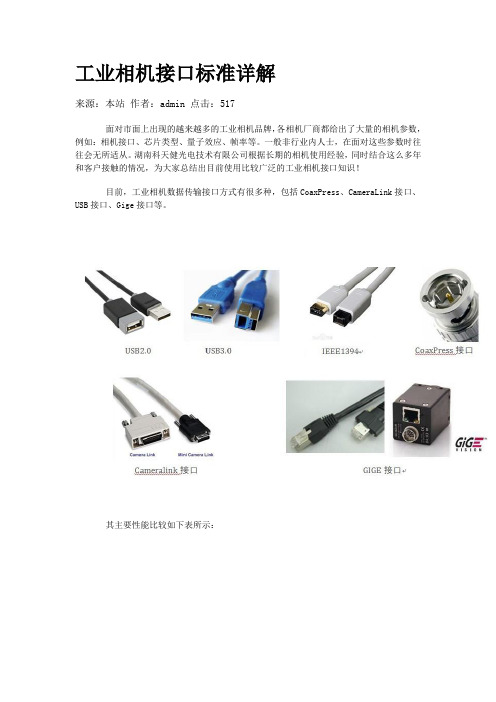
工业相机接口标准详解来源:本站作者:admin 点击:517面对市面上出现的越来越多的工业相机品牌,各相机厂商都给出了大量的相机参数,例如:相机接口、芯片类型、量子效应、帧率等。
一般非行业内人士,在面对这些参数时往往会无所适从。
湖南科天健光电技术有限公司根据长期的相机使用经验,同时结合这么多年和客户接触的情况,为大家总结出目前使用比较广泛的工业相机接口知识!目前,工业相机数据传输接口方式有很多种,包括CoaxPress、CameraLink接口、USB接口、Gige接口等。
其主要性能比较如下表所示:USB2.0USB 即“Universal Serial Bus ”,中文名称为通用串行总线。
这是近几年逐步在PC 领域广为应用的新型接口技术。
USB2.0则可以达到速度480Mbps,并且可以向下兼容USB1.1。
这几年,随着大量支持USB的个人电脑的普及,USB逐步成为个人电脑的标准接口已经是大势所趋。
在主机端,最新推出的个人电脑几乎100%支持USB;而在外设端,使用USB接口的设备也与日俱增,例如数码相机、扫描仪、游戏杆、磁带和软驱、图像设备、打印机、键盘、鼠标等等。
2000年制定的USB 2.0标准是真正的USB 2.0,被称为USB 2.0的高速(High-speed)版本,理论传输速度为480 Mbps,即60 MB/s,但实际传输速度一般不超过30 MB/s,采用这种标准的USB设备也比较多。
USB电缆的长度在不加级连装置的情况下为小于5m。
USB3.0USB3.0 ——也被认为是SuperSpeedUSB——为那些与PC或音频/高频设备相连接的各种设备提供了一个标准接口。
只是个硬件设备,计算机内只有安装USB3.0相关的硬件设备后才可以使用USB3.0相关的功能!从键盘到高吞吐量磁盘驱动器,各种器件都能够采用这种低成本接口进行平稳运行的即插即用连接,用户基本不用花太多心思在上面。
新的USB 3.0在保持与USB 2.0的兼容性的同时,还提供了下面的几项增强功能:(1)极大提高了带宽——高达5Gbps全双工(USB2.0则为480Mbps半双工)(2)实现了更好的电源管理(3)能够使主机为器件提供更多的功率,从而实现USB——充电电池、LED照明和迷你风扇等应用。
3-CameraLink接口-时序控制 (2)

CameraLink接口1.CameraLink接口简介1.1CameraLink标准概述Camera Link 技术标准是基于 National Semiconductor 公司的 Channel Link 标准发展而来的,而 Channel Link 标准是一种多路并行 LVDS 传输接口标准。
低压差分信号( LVDS )是一种低摆幅的差分信号技术,电压摆幅在 350mV 左右,具有扰动小,跳变速率快的特点,在无失传输介质里的理论最大传输速率在 1.923Gbps 。
90 年代美国国家半导体公司( National Semiconductor )为了找到平板显示技术的解决方案,开发了基于 LVDS 物理层平台的 Channel Link 技术。
此技术一诞生就被进行了扩展,用来作为新的通用视频数据传输技术使用。
如图1.1所示, Channel Link 由一个并转串信号发送驱动器和一个串转并信号接收器组成,其最高数据传输速率可达 2.38G 。
数据发送器含有 28 位的单端并行信号和 1 个单端时钟信号,将 28 位 CMOS/TTL 信号串行化处理后分成 4 路 LVDS 数据流,其 4 路串行数据流和 1 路发送 LVDS 时钟流在 5 路 LVDS 差分对中传输。
接收器接收从 4 路 LVDS 数据流和 1 路 LVDS 时钟流中把传来的数据和时钟信号恢复成 28 位的 CMOS/TTL 并行数据和与其相对应的同步时钟信号。
图1.1 camera link接口电路1.2CameraLink端口和端口分配1.2.1端口分配在基本配置模式中,端口 A 、 B 和 C 被分配到唯一的 Camera Link 驱动器 / 接收器对上;在中级配置模式中,端口 D 、 E 和 F 被分配到第二个驱动器 / 接收器对上;在完整配置模式中,端口 A 、 B 和 C 被分配到第一个驱动器 / 接收器对上,端口 D 、 E 和F 被分配到第二个驱动器 / 接收器对上,端口 G 和 H 被分配到第三个驱动器 / 接收器对上。
3-CameraLink接口-时序控制

CameraLink接口
1.CameraLink接口简介
1.1CameraLink标准概述
CameraLink技术标准是基于NationalSemiconductor公司的ChannelLink标准发展而来的,而ChannelLink标准是一种多路并行LVDS传输接口标准。
低压差分信号(LVDS)是一种低摆幅的差分信号技术,电压摆幅在350mV左右,具有扰动小,跳变速率快的特点,在无失传输介质里的理论最大传输速率在1.923Gbps。
90年代美国国家半导体公司(NationalSemiconductor)为了找到平板显示技术的解决方案,开发了基于LVDS物理层平台的
如图
位
5路LVDS
恢复成
A、B 和C
口G和芯
E和H,
那么
H的8
从
中读取处FPGA DDR 包括2RAM 另外,
子模块来完成位宽的转换。
2.4modelsim仿真结果
图2.4modelsim仿真结果
如图2.4,被测FPGA每来一个行同步,CameraLink模块获取行地址后读取DDR2中的数据写入缓存模块,等到下一个行同步来的时候把所读的数据从缓存模块中输出。
实际要求的是每个行同步来后要读取一行数据,大小为2048x12bit,为了缩小仿真时间,仿真时没一行的数据长度为:80x12bit。
图2.5五路CameraLink仿真输出
如图2.5,当下个行同步来的时候缓存数据输出,输出的数据时连续的。
CameraLink图像采集接口电路1(2)详解
CameraLink 图像采集接口电路1.Camera Link标准概述Camera Link 技术标准是基于 National Semiconductor 公司的 Channel Link 标准发展而来的,而 Channel Link 标准是一种多路并行 LVDS 传输接口标准。
低压差分信号( LVDS )是一种低摆幅的差分信号技术,电压摆幅在 350mV 左右,具有扰动小,跳变速率快的特点,在无失传输介质里的理论最大传输速率在 1.923Gbps 。
90 年代美国国家半导体公司( National Semiconductor )为了找到平板显示技术的解决方案,开发了基于 LVDS 物理层平台的 Channel Link 技术。
此技术一诞生就被进行了扩展,用来作为新的通用视频数据传输技术使用。
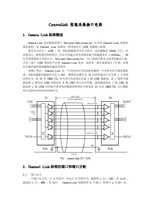
如图1 所示, Channel Link 由一个并转串信号发送驱动器和一个串转并信号接收器组成,其最高数据传输速率可达 2.38G 。
数据发送器含有 28 位的单端并行信号和 1 个单端时钟信号,将 28 位 CMOS/TTL 信号串行化处理后分成 4 路 LVDS 数据流,其 4 路串行数据流和 1 路发送 LVDS 时钟流在 5 路 LVDS 差分对中传输。
接收器接收从 4 路 LVDS 数据流和 1 路 LVDS 时钟流中把传来的数据和时钟信号恢复成 28 位的 CMOS/TTL 并行数据和与其相对应的同步时钟信号。
图1 camera link接口电路2.Channel Link标准的端口和端口分配2.1 .端口定义一个端口定义为一个 8 位的字,在这个 8 位的字中,最低的 1 位( LSB )是 bit0 ,最高的 1 位( MSB )是 bit7 。
Camera Link 标准使用 8 个端口,即端口 A 至端口 H 。
2.2 .端口分配在基本配置模式中,端口 A 、 B 和 C 被分配到唯一的 Camera Link 驱动器 / 接收器对上;在中级配置模式中,端口 D 、 E 和 F 被分配到第二个驱动器 / 接收器对上;在完整配置模式中,端口 A 、 B 和 C 被分配到第一个驱动器 / 接收器对上,端口 D 、 E 和 F 被分配到第二个驱动器 / 接收器对上,端口 G 和 H 被分配到第三个驱动器 / 接收器对上(见图2 )。
Cameralink简介
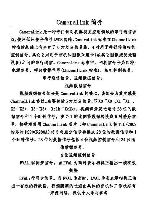
Cameralink简介CameraLink是一种专门针对机器视觉应用领域的串行通信协议,使用低压差分信号LVDS传输。
CameraLink标准在ChannelLink 标准的基础上有多加了6对差分信号线,4对用于并行传输相机设备:、1位图4位视频控制信号FVAL:帧同步信号。
当FVAL为高时表示相机正输出一帧有效数据LVAL:行同步信号。
当FVAL为高时,LVAL为高表示相机正输出一有效的行数据。
行消隐期的长短由具体的相机和工作状态有关。
DVAL:数据有效信号。
当FVAL为高并且LVAL为高时,DVAL 为高表示相机正输出有效的数据,该信号可用可不用,也可以作为数据传输中的校验位。
CLOCK:这一信号为图像的像素时钟信号,在行有效期内像素信号串行通信信号CameraLink标准定义了2对LVDS线缆用来实现相机与图像采集卡之间的异步串行通信控制。
相机和图像采集卡至少应该支持9600的波特率。
这两个串行信号是相机:SerTFG(相机串行输出端至图像采集卡串行输入端)SerTC(图像采集卡串行输出端至相机串行输入端) 其通信格式为:1位起始位、8位数据位、1位停止位、无奇偶校验位和握手位。
相机电源并不是由CameraLink连接器提供的,而是通过一个个4bits:;行有信号(DVAL),只有在数据有效信号为高电平时,图像采集卡才接受图像信息。
24bits图像数据可以是一个像素点的24-bitRGB数据、3个像素点的8-bit黑白图像数据、1到2个像素点的10-bit 或12-bit的黑白图像数据、一个像素点的14-bit或16-bit的黑白图像数据。
Medium模式需要两块Channe1Link的芯片和两个CameraLink 机械接口,发送器在每个像素时钟里发送4Obits数据,包括4bits 的图像使能信号和36bits的图像数据。
4bits图像使能信号与Base模式下相同。
36bits图像数据可以是一个像素点的36-bit 或到4个4bitsA口(8位))、)。
Cameralink协议简介.pdf

Cameralink简介CameraLink是一种专门针对机器视觉应用领域的串行通信协议,使用低压差分信号LVDS传输。
CameraLink标准在ChannelLink标准的基础上有多加了6对差分信号线,4对用于并行传输相机控制信号,其它2对用于相机和图像采集卡(或其它图像接受处理设备)之间的串行通信。
CameraLink标准中,相机信号分为四种: 电源信号、视频数据信号(ChannelLink标准)、相机控制信号、串行通信信号、视频数据信号。
视频数据信号视频数据信号部分是CameraLink的核心,该部分为其实就是Channel Link协议。
主要包括5对差分信号,即X0-~X0+、X1-~X1+、X2-~X2+、X3-~X3+、Xclk-~Xclk+;视频部分发送端将28位的数据信号和1个时钟信号,按7:1的比例将数据转换成5对差分信号,接收端使用Channel Link芯片(如Channel Link转TTL/CMOS 的芯片DS90CR288A)将5对差分信号转换成28位的数据信号和1个时钟信号。
28位的数据信号包括4位视频控制信号和24位图像数据信号。
4位视频控制信号FVAL:帧同步信号。
当FVAL为高时表示相机正输出一帧有效数据LVAL:行同步信号。
当FVAL为高时,LVAL为高表示相机正输出一有效的行数据。
行消隐期的长短由具体的相机和工作状态有关。
DVAL:数据有效信号。
当FVAL为高并且LVAL为高时,DVAL为高表示相机正输出有效的数据,该信号可用可不用,也可以作为数据传输中的校验位。
CLOCK:这一信号为图像的像素时钟信号,在行有效期内像素时钟的上升沿图像数据稳定。
值得说明的是,CLOCK信号单独采用一对LVDS信号传输,不管相机是否处于工作状态,CLOCK信号应该始终有效,它是ChannelLink芯片的输入时钟,是ChannelLink芯片之所以能在4对信号线中传输28位数据,就是因为对CLOCK信号7倍频的结果。
工业相机常用的传输接口
2. USB3.0接口是最新的USB规范,极大提高了带宽可高达5Gbps,实现了更好的电源管理,能够使主机为设备提供更多的功率输出,且使主机更快地识别器件,新的协议使得数据处理的效率更高。
3. 1394a/1394b接口俗称火线接口,现主要用于视频采集,数据传输率可高达400Mbps(1394a)和800Mbps(1394b),其利用等时性传输来保证实时性,便于安装,采用总线结构,支持热插拔,即插即用。
4. GigE是一种基于千以太网通信协议开发的相机接口标准,其特点是快捷的数据传输速率以及最远可达100米的传输距离。在工业机器视觉产品的应用中,GigE允许用户在很长距离上用标准线缆进行快速图像传输。它还能在不同厂商的软、硬件之间轻松实现互操作。
5. Cameralink在Channel link技术基础上增加了一些传输控制信号,并定义了一些相关传输标准。任何具有“Camera link”标志的产品可以方便地连接。其抗干扰、且传输带宽高达5.4Gbps。
工控机通过工业相机常用的传输接口包括:USB2.0、USB3.0、1394a/1394b、GigE、CameraLink、CoaXPress等。下面详细描述各接口的特点:
Cameralink协议简介

Cameralink简介CameraLink是一种专门针对机器视觉应用领域的串行通信协议,使用低压差分信号LVDS传输。
CameraLink标准在ChannelLink标准的基础上有多加了6对差分信号线,4对用于并行传输相机控制信号,其它2对用于相机和图像采集卡(或其它图像接受处理设备)之间的串行通信。
CameraLink标准中,相机信号分为四种: 电源信号、视频数据信号(ChannelLink标准)、相机控制信号、串行通信信号、视频数据信号。
视频数据信号视频数据信号部分是CameraLink的核心,该部分为其实就是Channel Link 协议。
主要包括5对差分信号,即X0-~X0+、X1-~X1+、X2-~X2+、X3-~X3+、Xclk-~Xclk+;视频部分发送端将28位的数据信号和1个时钟信号,按7:1的比例将数据转换成5对差分信号,接收端使用Channel Link芯片(如Channel Link 转TTL/CMOS的芯片DS90CR288A)将5对差分信号转换成28位的数据信号和1个时钟信号。
28位的数据信号包括4位视频控制信号和24位图像数据信号。
4位视频控制信号FVAL:帧同步信号。
当FVAL为高时表示相机正输出一帧有效数据LVAL:行同步信号。
当FVAL为高时,LVAL为高表示相机正输出一有效的行数据。
行消隐期的长短由具体的相机和工作状态有关。
DVAL:数据有效信号。
当FVAL为高并且LVAL为高时,DVAL为高表示相机正输出有效的数据,该信号可用可不用,也可以作为数据传输中的校验位。
CLOCK:这一信号为图像的像素时钟信号,在行有效期内像素时钟的上升沿图像数据稳定。
值得说明的是,CLOCK信号单独采用一对LVDS信号传输,不管相机是否处于工作状态,CLOCK信号应该始终有效,它是ChannelLink芯片的输入时钟,是ChannelLink芯片之所以能在4对信号线中传输28位数据,就是因为对CLOCK信号7倍频的结果。
cameralink布线规则

cameralink布线规则CameraLink是一种用于将摄像头与图像处理系统连接的标准化接口。
为了确保数据传输的可靠性和稳定性,摄像头与图像处理系统之间的布线需要符合一定的规范和标准。
以下是CameraLink布线规则的详细描述。
1. 布线距离根据CameraLink标准,摄像头与图像处理系统之间的最大布线距离为10米。
超过这个距离将导致信号损失和噪音干扰。
因此,在实际布线过程中,应尽量减少布线长度,以确保信号的稳定传输。
2. 布线类型CameraLink接口通常使用同轴电缆进行布线。
同轴电缆是一种具有高抗干扰特性的传输介质,可有效减少信号干扰和损失。
在选择同轴电缆时,应选择品质可靠、屏蔽性能好的产品,以确保信号的稳定传输。
3. 布线颜色为了方便识别和管理,CameraLink布线通常使用不同颜色的电缆进行标识。
根据CameraLink标准,摄像头端使用蓝色电缆,图像处理系统端使用黑色电缆。
这样做可以方便用户识别和安装。
4. 布线连接在布线连接过程中,应注意保持连接头的良好质量以及连接的可靠性。
连接头应具备良好的插拔性能,不易出现松动和接触不良的情况。
为了保证连接质量,建议使用金属外壳的连接头,以提供更好的电磁屏蔽性能。
5. 布线保护为了保护CameraLink布线免受外界干扰和物理损坏,可以采取以下保护措施:- 使用导线槽或塑料管将电缆固定在墙壁或地面上,保持电缆整齐有序。
- 在连接头处使用护套和护套夹保护连接点,防止拉扯和弯曲引起的损坏。
- 使用电缆套圈对电缆部分进行固定,防止拉力或插拔动作引起的电缆松脱。
6. 布线测试完成布线后,应进行测试以确保信号传输的稳定性和质量。
主要测试项目包括电缆连通性测试、信号质量测试和误码率测试。
通过这些测试可以及时发现和解决布线中存在的问题,确保CameraLink系统的正常运行。
总结:CameraLink布线规则是确保摄像头与图像处理系统之间数据传输稳定和可靠的关键要素。
CameraLink接口标准与协议
Camera LinkSpecifications of theCamera LinkInterface Standard forDigital Cameras andFrame GrabbersCamera Link SpecificationsOctober 2000AcknowledgementsParticipating CompaniesThe following companies contributed to the development and definition ofthe Camera Link standard.•Basler•Cognex•Coreco•DALSA•Data Translation•Datacube•EPIX•Euresys•Foresight Imaging•Integral Technologies•Matrox•National Instruments•PULNiX AmericaRights and TrademarksPULNiX America, Inc., as chair of this ad hoc Camera Link committee, hasapplied for U.S. trademark protection for the term "Camera Link" to secureit for the mutual benefit of industry members. PULNiX will issue aperpetual royalty-free license to any industry member (includingcompetitors) for the use of the "Camera Link" trademark on the conditionthat it is used only in conjunction with products that are fully compliant tothis standard. PULNiX will not require licensed users of the trademark tocredit PULNiX with ownership.3M™ is a trademark of the 3M Company.Channel Link™ is a trademark of National Semiconductor.Flatlink™ is a trademark of Texas Instruments.Panel Link™ is a trademark of Silicon Image.About this DocumentThe following specifications provide a framework for Camera Linkcommunication. The specifications are deliberately defined to be open,allowing camera and frame grabber manufacturers to differentiate theirproducts. Additional recommendations may be added at a later date, whichwill not affect the accuracy of the information in this document.ContentsAcknowledgementsParticipating Companies (ii)Rights and Trademarks (ii)About this DocumentChapter 1Camera LinkIntroduction....................................................................................................................1-1 LVDS Technical Description.........................................................................................1-1 Channel Link..................................................................................................................1-2 Technology Benefits......................................................................................................1-3 Smaller Connectors and Cables.......................................................................1-3High Data Transmission Rates........................................................................1-3 Chapter 2Camera Signal RequirementsVideo Data.......................................................................................................2-1Camera Control Signals...................................................................................2-1Communication...............................................................................................2-2Power...............................................................................................................2-2 Chapter 3Port AssignmentsPort Definition.................................................................................................3-1 Chapter 4Bit AssignmentsChapter 5Camera Link ConnectionsMDR 26-pin Connector...................................................................................5-1Camera Link Cable Pinout..............................................................................5-2Shielding Recommendations...........................................................................5-3ContentsAppendix AChipset CriteriaAppendix BAPI FunctionsAppendix CBit Assignments According to ConfigurationAppendix DCamera Link Cabling InformationFiguresFigure 1-1.Channel Link Operation........................................................................1-2 Figure 3-1.Data Routing for Base, Medium, and Full Configurations...................3-2 Figure 3-2.Block Diagram of Base, Medium, and Full Configuration ..................3-3 Figure 5-1.Camera Link Cable...............................................................................5-1 Figure D-1.Dimensions of 3M Connector...............................................................D-1 Figure D-2.3M Part Number Ordering Information................................................D-3 TablesTable 3-1.Port Assignments According to Configuration.....................................3-1 Table 4-1.Camera Link Bit Assignment................................................................4-1 Table patible National Semiconductor Parts...........................................A-1 Table C-1.Bit Assignments for Base Configuration..............................................C-1 Table C-2.Bit Assignment for Medium Configuration..........................................C-2 Table C-3.Bit Assignment for Full Configuration.................................................C-4 Table D-1.Shell Options.........................................................................................D-3 Table D-2.3M Boardmount Receptacle Part Numbers..........................................D-41 Camera LinkIntroductionCamera Link is a communication interface for vision applications. Theinterface extends the base technology of Channel Link to provide aspecification more useful for vision applications.For years, the scientific and industrial digital video market has lacked astandard method of communication. Both frame grabbers and cameramanufacturers developed products with different connectors, making cableproduction difficult for manufacturers and very confusing for consumers. Aconnectivity standard between digital cameras and frame grabbers is longoverdue and will become even more necessary as data rates continue toincrease.Increasingly diverse cameras and advanced signal and data transmissionshave made a connectivity standard like Camera Link a necessity. TheCamera Link interface will reduce support time, as well as the cost of thatsupport. The standard cable will be able to handle the increased signalspeeds, and the cable assembly will allow customers to reduce their coststhrough volume pricing.LVDS Technical DescriptionLow Voltage Differential Signaling (LVDS) is a high-speed, low-powergeneral purpose interface standard. The standard, known asANSI/TIA/EIA-644, was approved in March 1996. LVDS uses differentialsignaling, with a nominal signal swing of 350 mV differential. The lowsignal swing decreases rise and fall times to achieve a theoretical maximumtransmission rate of 1.923 Gbps into a loss-less medium. The low signalswing also means that the standard is not dependent on a particular supplyvoltage. LVDS uses current-mode drivers, which limit power consumption.The differential signals are immune to ±1 V common volt noise.Channel LinkNational Semiconductor developed the Channel Link technology as asolution for flat panel displays, based on LVDS for the physical layer. Thetechnology was then extended into a method for general purpose datatransmission. Channel Link consists of a driver and receiver pair. Thedriver accepts 28 single-ended data signals and a single-ended clock. Thedata is serialized 7:1, and the four data streams and a dedicated clock aredriven over five LVDS pairs. The receiver accepts the four LVDS datastreams and LVDS clock, and then drives the 28 bits and a clock to theboard. Figure1-1 illustrates Channel Link operation.Figure 1-1. Channel Link OperationTechnology BenefitsSmaller Connectors and CablesChannel Link’s transmission method requires fewer conductors to transferdata. Five pairs of wires can transmit up to 28 bits of data. These wiresreduce the size of the connector, allowing smaller cameras to bemanufactured.High Data Transmission RatesThe data transmission rates of the Channel Link chipset (up to 2.38Gbits/s)support the current trend of increasing transfer speeds.2 Camera Signal RequirementsThis section provides definitions for the signals used in the Camera Linkinterface. The standard Camera Link cable provides camera control signals,serial communication, and video data.Video DataThe Channel Link technology is integral to the transmission of video data.Image data and image enables are transmitted on the Channel Link bus.Four enable signals are defined as:•FV AL—Frame V alid (FV AL) is defined HIGH for valid lines.•LV AL—Line V alid (LV AL) is defined HIGH for valid pixels.•DV AL—Data V alid (DV AL) is defined HIGH when data is valid.•Spare— A spare has been defined for future use.All four enables must be provided by the camera on each Channel Linkchip. All unused data bits must be tied to a known value by the camera.For more information on image data bit allocations, see Section 3,Bit Assignments, and Appendix C, Bit Assignments According toConfiguration.Camera Control SignalsFour LVDS pairs are reserved for general-purpose camera control. Theyare defined as camera inputs and frame grabber outputs. Cameramanufacturers can define these signals to meet their needs for a particularproduct. The signals are:•Camera Control 1 (CC1)•Camera Control 2 (CC2)•Camera Control 3 (CC3)•Camera Control 4 (CC4)CommunicationTwo LVDS pairs have been allocated for asynchronous serialcommunication to and from the camera and frame grabber. Cameras andframe grabbers should support at least 9600 baud. These signals are•SerTFG—Differential pair with serial communications to the framegrabber.•SerTC—Differential pair with serial communications to the camera.The serial interface will have the following characteristics: one start bit, onestop bit, no parity, and no handshaking.It is recommended that frame grabber manufacturers supply both a userinterface and a software application programmming interface (API) forusing the asynchronous serial communication port. The user interface willconsist of a terminal program with minimal capabilities of sending andreceiving a character string and sending a file of bytes. The software APIwill provide functions to enumerate boards and send or receive a characterstring. See Appendix B, API Functions,for a suggested softwareapplication program interface (API).PowerPower will not be provided on the Camera Link connector. The camera willreceive power through a separate cable. Each camera manufacturer willdefine their own power connector, current, and voltage requirements.3 Port AssignmentsThe Camera Link interface has three configurations. Since a singleChannel Link chip is limited to 28 bits, some cameras may require severalchips in order to transfer data efficiently. The naming conventions for thevarious configurations are:•Base—Single Channel Link chip, single cable connector.•Medium—Two Channel Link chips, two cable connectors.•Full—Three Channel Link chips, two cable connectors.Port DefinitionA port is defined as an 8-bit word. The Least Significant Bit (LSB) is bit 0,and the Most Significant Bit (MSB) is bit 7. The Camera Link interfaceutilizes the 8 ports of A-H.The following table shows the port assignment for the Base, Medium, andFull Configurations.Table 3-1. Port Assignments According to ConfigurationConfiguration Ports Supported Number of Chips Number of ConnectorsBase A, B, C11 Medium A, B, C, D, E, F22 Full A, B, C, D, E, F, G, H32Figure 3-1. Data Routing for Base, Medium, and Full Configurations The block diagram shown in Figure 3 illustrates the Base, Medium, and Full Configurations.Figure 3-2. Block Diagram of Base, Medium, and Full Configuration4Table 4-1. Camera Link Bit Assignment (Continued) Tx Input Signal Name28-bit Solution Pin Name Port B3, Port E3, Port H3TX/RX 12Port B4, Port E4, Port H4TX/RX 13Port B5, Port E5, Port H5TX/RX 14Port B6, Port E6, Port H6TX/RX 10Port B7, Port E7, Port H7TX/RX 11Port C0, Port F0TX/RX 15Port C1, Port F1TX/RX 18Port C2, Port F2TX/RX 19Port C3, Port F3TX/RX 20Port C4, Port F4TX/RX 21Port C5, Port F5TX/RX 22Port C6, Port F6TX/RX 16Port C7, Port F7TX/RX 175Camera Link Cable Pinout.Table 5-1. MDR-26 Connector AssignmentsMedium and Full ConfigurationsBase Configuration (with Camera Control and Serial Communication)Camera ConnectorFrameGrabberConnectorChannelLinkSignalCableNameCameraConnectorFrameGrabberConnectorChannelLinkSignal11innershield InnerShield11innershield1414innershield InnerShield1414innershield225Y0-PAIR1-225X0-1512Y0+PAIR1+1512X0+ 324Y1-PAIR2-324X1-1611Y1+PAIR2+1611X1+ 423Y2-PAIR3-423X2-1710Y2+PAIR3+1710X2+ 522Yclk-PAIR4-522Xclk-189Yclk+PAIR4+189Xclk+ 621Y3-PAIR5-621X3-198Y3+PAIR5+198X3+ 720100 ΩPAIR6+720SerTC+ 207terminated PAIR6-207SerTC-819Z0-PAIR7-819SerTFG-216Z0+PAIR7+216SerTFG+ 918Z1-PAIR8-918CC1-225Z1+PAIR8+225CC1+ 1017Z2-PAIR9+1017CC2+ 234Z2+PAIR9-234CC2-Shielding RecommendationsThe outer shield of the cable is tied to the connector shell. It isrecommended that the inner shell be tied to digital ground in cameras and tied through a resister to digital ground in the frame grabbers. It isrecommended that a 0 Ω resistor be installed in the factory. If necessary, that resistor can be removed in the field and replaced with a high-value resistor and parallel capacitor. Unused pairs should be terminated to 100Ω at their respective ends of the cable.NoteAll pairs are individually shielded with aluminum foil. Pair shields are wrapped aluminum out and are in contact with four internal drains (digital ground). Outer braid and foil (chassis ground) are isolated from inner drains (digital ground).234Z2+PAIR9-234CC2-1116Zclk-PAIR10-1116CC3-243Zclk+PAIR10+243CC3+1215Z3-PAIR11+1215CC4+252Z3+PAIR11-252CC4-1313inner shield Inner Shield 1313inner shield 2626inner shieldInner Shield2626inner shieldTable 5-1. MDR-26 Connector Assignments (Continued)Medium and Full Configurations Base Configuration (with Camera Control and Serial Communication)Camera ConnectorFrame Grabber ConnectorChannel Link Signal Cable Name Camera ConnectorFrame Grabber ConnectorChannel Link SignalAChipset CriteriaCamera Link uses 28-bit Channel Link chips manufactured by National Semiconductor. Because of potential interface issues, chips that use a similar technology, such as Flatlink by Texas Instruments and Panel Link by Silicon Image, may not be compatible with the Camera Link interface. Receivers and drivers with different operating frequencies will interoperate over the frequency range that both support. The following table lists some compatible National Semiconductor parts.The pinout of the MDR 26 connector was chosen for optimal PWB trace routing using an LVDS driver/receiver pair for camera control signals. The following are the recommended National Semiconductor parts for the pair:DS90LV047 3.3 V transmitter DS90LV0483.3 VreceiverTable A-1. Compatible National Semiconductor PartsProduct Supply Voltage SpeedDS90CR281 5 V 40 MHz DS90CR282 5 V 40 MHz DS90CR283 5 V 66 MHz DS90CR284 5 V 66 MHz DS90CR285 3.3 V 66 MHz DS90CR286 3.3 V 66 MHz DS90CR286A 3.3 V 66 MHz DS90CR287 3.3 V 85 MHz DS90CR288 3.3 V 75 MHz DS90CR288A3.3 V85 MHzB API FunctionsA consistent, known API for asynchronous serial reading and writingallows camera vendors to write a frame grabber-independent,camera-specific configuration utility. The following API offers a solutionfor camera vendors that is easy for frame grabber manufacturers toimplement, regardless of the actual implementation methods used forasynchronous serial communication.All frame grabbers provide a .dll file named clser***.dll, where ***is specific to the frame grabber vendor. There are four functions withinthat .dll:•clSerialInit—Initialize the serial communication fora specific board.•clSerialRead—Read bytes from the camera.•clSerialWrite—Write bytes to the camera.•clSerialClose—Close the serial communication.clSerialInitFormatint clSerialInit(unsigned long serialIndex, void** serialRefPtr)PurposeThis function initializes the device referred to by serialIndex, and returns a pointer to aninternal serial reference structure.ParametersName Direction Description serialIndex input A zero-based index value. For nserial devices in the systemsupported by this library,serialIndex has a range of0to(n-1).serialRefPtr output Points to a value that contains, on asuccessful call, a pointer to thevendor-specific reference to thecurrent session.Return ValueA vendor-specific error value that follows these conventions:• A negative value indicates a fatal error.• A zero value indicates success.• A positive value indicates a warning.Formatint clSerialRead(void* serialRef, char* buffer,unsigned long* bufferSizeunsigned long serialTimeout)PurposeThis function reads the serial device referenced by serialRef.ParametersName Direction Description serialRef input The value obtained from theclSerialInit function.buffer output Points to a user-allocated buffer.Upon a successful call, buffercontains the data read from theserial device.bufferSize input/output Contains the buffer size indicatingthe maximum number of bytes thatthe buffer can accommodate. Upona successful call, bufferSizecontains the number of bytes readsuccessfully from the serial device.serialTimeout input Indicates the timeout inmilliseconds.Return ValueA vendor-specific error value that follows these conventions:• A negative value indicates a fatal error.• A zero value indicates success.• A positive value indicates a warning.Formatint clSerialWrite(void* serialRef, char* buffer,unsigned long* bufferSizeunsigned long SerialTimeout)PurposeThis function writes the data in the buffer to the serial device referenced by SerialRef. ParametersName Direction Description serialRef input The value obtained from theclSerialInit function.buffer input Contains data to write to the serialport.bufferSize input/output Contains the buffer size indicatingthe maximum number of bytes thatthe buffer can accommodate. Upona successful call, bufferSizecontains the number of bytes readsuccessfully from the serial device.serialTimeout input Indicates the timeout inmilliseconds.Return ValueA vendor-specific error value that follows these conventions:• A negative value indicates a fatal error.• A zero value indicates success.• A positive value indicates a warning.Formatvoid clSerialClose(void* serialRef)PurposeThis function closes the serial device and cleans up the resources associated with serialRef.Upon return, serialRef is no longer usable.ParametersName Direction Description serialRef input The value obtained from theclSerialInit function forclean up.Return ValueA vendor-specific error value that follows these conventions:• A negative value indicates a fatal error.• A zero value indicates success.• A positive value indicates a warning.Header FileThe following is an example of an appropriate header file for this API: #ifndef _CLSER____H_#define _CLSER____H_#ifndef CLSER___EXPORT#define CLSER___EXPORT __declspec(dllimport)#endif#ifndef CLSER___CC#define CLSER___CC __cdecl#endif#ifdef __cplusplusextern "C"{#endifCLSER___EXPORT int CLSER___CCclSerialInit(unsigned long serialIndex, void** serialRefPtr);CLSER___EXPORT int CLSER___CCclSerialRead(void* serialRef, char* buffer,unsigned long* bufferSize, unsigned long serialTimeout);CLSER___EXPORT int CLSER___CCclSerialWrite(void* serialRef, char* buffer, unsigned long* bufferSize, unsigned long serialTimeout);CLSER___EXPORT void CLSER___CCclSerialClose(void* serialRef);#ifdef __cplusplus}#endif#endifNote Using a single .dll file prevents the user from accessing driver software frommultiple vendors at the same time; therefore, camera vendors using this API must load all .dll files with the name clser*.dll on the system and then provide a method for the user to select the correct vendor for the board they are using. The camera vendor should use LoadLibrary and GetProcAddress to find these functions. The camera vendors should also provide a way for users to select a particular frame grabber, and then use clSerialRead and clSerialWrite to communicate with the camera attached to their board.CBit Assignments According to ConfigurationTable C-1. Bit Assignments for Base ConfigurationBase ConfigurationPort/bit 8-bit x1~3*10-bit x1~212-bit x1~214-bit x 116-bit x 124-bitRGBPort A0A0A0A0A0A0R0 Port A1A1A1A1A1A1R1 Port A2A2A2A2A2A2R2 Port A3A3A3A3A3A3R3 Port A4A4A4A4A4A4R4 Port A5A5A5A5A5A5R5 Port A6A6A6A6A6A6R6 Port A7A7A7A7A7A7R7 Port B0B0A8A8A8A8G0 Port B1B1A9A9A9A9G1 Port B2B2nc A10A10A10G2 Port B3B3nc A11A11A11G3 Port B4B4B8B8A12A12G4 Port B5B5B9B9A13A13G5 Port B6B6nc B10nc A14G6 Port B7B7nc B11nc A15G7 Port C0C0B0B0nc nc B0 Port C1C1B1B1nc nc B1Port C2C2B2B2nc nc B2Port C3C3B3B3nc nc B3Port C4C4B4B4nc nc B4Port C5C5B5B5nc nc B5Port C6C6B6B6nc nc B6Port C7C7B7B7ncncB7* If only using a single channel, use Port A. If using two channels, use Port A and B.Table C-2. Bit Assignment for Medium ConfigurationMedium ConfigurationPort/bit 8-bit x 410-bit x 3~412-bit x 3~430-bit RGB36-bit RGBPort A0A0A0A0R0R0Port A1A1A1A1R1R1Port A2A2A2A2R2R2Port A3A3A3A3R3R3Port A4A4A4A4R4R4Port A5A5A5A5R5R5Port A6A6A6A6R6R6Port A7A7A7A7R7R7Port B0B0A8A8R8R8Port B1B1A9A9R9R9Port B2B2nc A10nc R10Port B3B3nc A11nc R11Port B4B4B8B8B8B8Table C-1. Bit Assignments for Base Configuration (Continued)Base ConfigurationPort/bit 8-bit x 1~3*10-bit x 1~212-bit x 1~214-bit x 116-bit x 124-bit RGBMedium ConfigurationPort/bit8-bit x 410-bit x 3~412-bit x 3~430-bit RGB 36-bit RGB Port B5B5B9B9B9B9 Port B6B6nc B10nc B10 Port B7B7nc B11nc B11 Port C0C0B0B0B0B0 Port C1C1B1B1B1B1 Port C2C2B2B2B2B2 Port C3C3B3B3B3B3 Port C4C4B4B4B4B4 Port C5C5B5B5B5B5 Port C6C6B6B6B6B6 Port C7C7B7B7B7B7 Port D0D0D0D0nc nc Port D1D1D1D1nc nc Port D2D2D2D2nc nc Port D3D3D3D3nc nc Port D4D4D4D4nc nc Port D5D5D5D5nc nc Port D6D6D6D6nc nc Port D7D7D7D7nc nc Port E0nc C0C0G0G0 Port E1nc C1C1G1G1 Port E2nc C2C2G2G2 Port E3nc C3C3G3G3 Port E4nc C4C4G4G4 Port E5nc C5C5G5G5Medium ConfigurationPort/bit8-bit x 410-bit x 3~412-bit x 3~430-bit RGB 36-bit RGB Port E6nc C6C6G6G6 Port E7nc C7C7G7G7 Port F0nc C8C8G8G8 Port F1nc C9C9G9G9 Port F2nc nc C10nc G10 Port F3nc nc C11nc G11 Port F4nc D8D8nc nc Port F5nc D9D9nc nc Port F6nc nc D10nc nc Port F7nc nc D11nc ncTable C-3. Bit Assignment for Full ConfigurationFull ConfigurationPort/bit8-bit x 8Port/bit8-bit x 8Port A0A0Port E0E0Port A1A1Port E1E1Port A2A2Port E2E2Port A3A3Port E3E3Port A4A4Port E4E4Port A5A5Port E5E5Port A6A6Port E6E6Port A7A7Port E7E7Port B0B0Port F0F0Port B1B1Port F1F1Port B2B2Port F2F2Table C-3. Bit Assignment for Full Configuration (Continued)Full ConfigurationPort/bit8-bit x 8Port/bit8-bit x 8 Port B3B3Port F3F3 Port B4B4Port F4F4 Port B5B5Port F5F5 Port B6B6Port F6F6 Port B7B7Port F7F7 Port C0C0Port G0G0 Port C1C1Port G1G1 Port C2C2Port G2G2 Port C3C3Port G3G3 Port C4C4Port G4G4 Port C5C5Port G5G5 Port C6C6Port G6G6 Port C7C7Port G7G7 Port D0D0Port H0H0 Port D1D1Port H1H1 Port D2D2Port H2H2 Port D3D3Port H3H3 Port D4D4Port H4H4 Port D5D5Port H5 H5 Port D6D6Port H6H6 Port D7D7Port H7H7DOrdering InformationCable assemblies and boardmount receptacles are available from 3M. For more information on 3M products, see the 3M Web site at .Cable Assembly Part NumbersFigure D-2. 3M Part Number Ordering InformationTable D-1. Shell OptionsShell Option B C Thumbscrew Overmold Shell 1.58[40.2].55[14.0]Thumbscrew Shell Kit1.55[39.4].51[12.8]Boardmount Receptacle Part NumbersThe following table lists the 3M boardmount receptacle part numbers.Table D-2. 3M Boardmount Receptacle Part NumbersPart Number Type Mount N10226-52xxVC MDR 26 Right Angle Thru-hole10266-55G3VC MDR 26 Right Angle Thru-hole10226-6212VC MDR 26 Vertical Thru-hole10226-1A10VE MDR 26 Right Angle SMT10226-2200VE MDR 26 Vertical SMT。
工业相机之数字接口—CameraLinkGigE
工业相机之数字接口—CameraLinkGigE工业相机的数据接口可以分为“数字接口”和“模拟接口”两大类。
前者传输的是数字信号,后者是模拟信号。
数字信号相较于模拟信号来说有很多优点,比如抗干扰能力强、易于加密、便于后续处理等等。
数字接口主要包括以下几类:Camera Link接口、IEEE 1394接口、USB接口、GigE接口、CoaXPress接口。
结合立鼎光电短波红外相机数字接口,我们将重点介绍下 Camera Link接口和GigE接口。
Camera Link接口图1 立鼎光电Camera Link 接口的相机对于采用Camera Link接口的相机来说,它的特点是图像的数据量大、带宽要求高、传输速度快,同时需要配合Camera Link采集卡来使用,Camera Link采集卡一般通过PCI-E接口安装在控制计算机上(对于早期的采集卡,低端型号使用的是PCI接口,型号PCI-X接口),如图2所示。
图2 PCI-E接口的Camera Link图像采集卡另外,Camera Link接口还有“大口”(MDR)和“小口”(SDR)之分,二者的引脚定义完全相同,只是在体积上不一样,如图3所示。
为了使用方便,工业相机一般都使用“小口”的。
图3 Camera Link“大口”和“小口”的对比此外,需要注意的是:Camera Link接口并不支持热插拔。
当相机带电工作期间,严禁拔下数据接口,这样有一定的概率会损坏相机,切记!图4 Camera Link接口相机连接示意图GigE接口图5 立鼎光电GigE 接口的相机GigE接口是一种基于千兆以太网通信协议开发的相机接口标准,其主要包括数据传输速率高、传输距离远等特点。
正是因为GigE接口标准的这些特点,也让GigE工业相机相比其他相机来说,具有一定的性能优势。
例如:GigE相机相对于Camera Link相机而言,GigE相机的优势就在于其传输距离长、无需图像采集卡和更偏重于图像处理功能;相对于IEEE 1394相机而言,GigE相机的最大数据率更高,传输距离更长;而相对于USB相机而言,GigE的优势在于其具有更完整的标准、更高的最大数据率、更长的传输距离。
3-CameraLink接口-时序控制
CameraLink接口1.CameraLink接口简介1.1CameraLink标准概述Camera Link 技术标准是基于 National Semiconductor 公司的 Channel Link 标准发展而来的,而 Channel Link 标准是一种多路并行 LVDS 传输接口标准。
低压差分信号( LVDS )是一种低摆幅的差分信号技术,电压摆幅在 350mV 左右,具有扰动小,跳变速率快的特点,在无失传输介质里的理论最大传输速率在 1.923Gbps 。
90 年代美国国家半导体公司( National Semiconductor )为了找到平板显示技术的解决方案,开发了基于 LVDS 物理层平台的 Channel Link 技术。
此技术一诞生就被进行了扩展,用来作为新的通用视频数据传输技术使用。
如图1.1所示, Channel Link 由一个并转串信号发送驱动器和一个串转并信号接收器组成,其最高数据传输速率可达 2.38G 。
数据发送器含有 28 位的单端并行信号和 1 个单端时钟信号,将 28 位 CMOS/TTL 信号串行化处理后分成 4 路 LVDS 数据流,其 4 路串行数据流和 1 路发送 LVDS 时钟流在 5 路 LVDS 差分对中传输。
接收器接收从 4 路 LVDS 数据流和 1 路 LVDS 时钟流中把传来的数据和时钟信号恢复成 28 位的 CMOS/TTL 并行数据和与其相对应的同步时钟信号。
图1.1 camera link接口电路1.2CameraLink端口和端口分配1.2.1端口分配在基本配置模式中,端口 A 、 B 和 C 被分配到唯一的 Camera Link 驱动器 / 接收器对上;在中级配置模式中,端口 D 、 E 和 F 被分配到第二个驱动器 / 接收器对上;在完整配置模式中,端口 A 、 B 和 C 被分配到第一个驱动器 / 接收器对上,端口 D 、 E 和F 被分配到第二个驱动器 / 接收器对上,端口 G 和 H 被分配到第三个驱动器 / 接收器对上。
CameraLink接口数字相机图像显示装置解读

Camera Link接口数字相机图像显示装置(技术)摘要:由于目前基于CameraLink接口的各种相机都不能直接显示,因此本文基于Xilinx公司的Spartan3系列FPGA XC3S1000-6FG456I设计了一套实时显示系统,该系统可以在不通过系统机的情况下,完成对相机CameraLink信号的接收、缓存、读取并显示。
系统采用两片SDRAM作为帧缓存,将输入的CameraLink信号转换成帧频为75Hz,分辨率为1,024×768的XGA格式信号,并采用ADV7123JST芯片实现数模转换,将芯片输出的信号送到VGA接口,通过VGA显示器显示出来。
设计的系统可以应用于各种基于CameraLink接口的相机输出信号的实时显示。
关键词:CameraLink; FPGA; SDRAM控制器;实时显示Research on the Real-time Display Technology Based on CameraLinkAbstract: All cameras based on the CameraLink interface cannot be displayed directly at present. Therefore, we designed a real-time display system based on the Xilinx Spartan3 FPGA XC3S1000-6FG456I.Our system could receive, store, read and display the CameraLink signal without the system computer. Two SDRAMs were used as frame storage. Input CameraLink signal was converted to XGA signal with 1024×768 pixles/frame at 75 frame/s. The ADV7123JST was used as D/A convertor. Its output signal was transmitted to the VGA interface and displayed on the screen of the VGA monitor. Our system could display the output signal of all cameras based on the CameraLink interface.Keywords: CameraLink; FPGA; SDRAM controller; real-time display目录第一章绪论 (3)1.1 引言 (3)1.2数字图像处理的发展 (3)1.3 目的及意义 (4)1.4 国内外研究现状 (5)第2章视频显示原理和显示格式的转换算法综述 (7)2.1视频显示的原理 (7)2.2目前视频显示格式转换算法综述 (8)2.2.1图像尺寸变换的插值方法综述 (9)2.2.2每秒帧数变换方法综述 (11)2.2.3插值算法选择判断的原则 (11)第三章视频显示格式转换的插值算法方案 (11)3.1图像尺寸变换采用的算法方案 (12)3.2每秒帧数变换采用的算法方案 (14)3.3视频显示格式转换中的像素处理方案 (15)第四章实时显示系统装置 (17)4.1.实时显示系统总体设计 (17)4.2 FPGA概述 (18)4.3 Camera Link结构与原理 (20)4.4 SDRAM控制器设计 (22)4.5 VGA显示接口设计 (23)参考文献 (25)第一章绪论1.1 引言Cameralink相机以其可靠性高,稳定性好,独立性好和易用等优势,成为现阶段工业大分辨率数字相机的必配接口,相机LVDS信号由专业图像采集卡解码通过一台性能良好的计算机计算最后在计算机显示器上完成图像显示或在计算机硬盘上存储等后续数字图像处理操作。
CameraLink图像采集接口电路1(2)

CameraLink 图像采集接口电路1.Camera Link标准概述Camera Link 技术标准是基于 National Semiconductor 公司的 Channel Link 标准发展而来的,而 Channel Link 标准是一种多路并行 LVDS 传输接口标准。
低压差分信号( LVDS )是一种低摆幅的差分信号技术,电压摆幅在 350mV 左右,具有扰动小,跳变速率快的特点,在无失传输介质里的理论最大传输速率在 1.923Gbps 。
90 年代美国国家半导体公司( National Semiconductor )为了找到平板显示技术的解决方案,开发了基于 LVDS 物理层平台的 Channel Link 技术。
此技术一诞生就被进行了扩展,用来作为新的通用视频数据传输技术使用。
如图1 所示, Channel Link 由一个并转串信号发送驱动器和一个串转并信号接收器组成,其最高数据传输速率可达 2.38G 。
数据发送器含有 28 位的单端并行信号和 1 个单端时钟信号,将 28 位 CMOS/TTL 信号串行化处理后分成 4 路 LVDS 数据流,其 4 路串行数据流和 1 路发送 LVDS 时钟流在 5 路 LVDS 差分对中传输。
接收器接收从 4 路 LVDS 数据流和 1 路 LVDS 时钟流中把传来的数据和时钟信号恢复成 28 位的 CMOS/TTL 并行数据和与其相对应的同步时钟信号。
图1 camera link接口电路2.Channel Link标准的端口和端口分配2.1 .端口定义一个端口定义为一个 8 位的字,在这个 8 位的字中,最低的 1 位( LSB )是 bit0 ,最高的 1 位( MSB )是 bit7 。
Camera Link 标准使用 8 个端口,即端口 A 至端口 H 。
2.2 .端口分配在基本配置模式中,端口 A 、 B 和 C 被分配到唯一的 Camera Link 驱动器 / 接收器对上;在中级配置模式中,端口 D 、 E 和 F 被分配到第二个驱动器 / 接收器对上;在完整配置模式中,端口 A 、 B 和 C 被分配到第一个驱动器 / 接收器对上,端口 D 、 E 和 F 被分配到第二个驱动器 / 接收器对上,端口 G 和 H 被分配到第三个驱动器 / 接收器对上(见图2 )。
CameraLink图像采集接口电路1(2)

CameraLink 图像采集接口电路1.Camera Link标准概述Camera Link 技术标准是基于 National Semiconductor 公司的 Channel Link 标准发展而来的,而 Channel Link 标准是一种多路并行 LVDS 传输接口标准。
低压差分信号( LVDS )是一种低摆幅的差分信号技术,电压摆幅在 350mV 左右,具有扰动小,跳变速率快的特点,在无失传输介质里的理论最大传输速率在 1.923Gbps 。
90 年代美国国家半导体公司( National Semiconductor )为了找到平板显示技术的解决方案,开发了基于 LVDS 物理层平台的 Channel Link 技术。
此技术一诞生就被进行了扩展,用来作为新的通用视频数据传输技术使用。
如图1 所示, Channel Link 由一个并转串信号发送驱动器和一个串转并信号接收器组成,其最高数据传输速率可达 2.38G 。
数据发送器含有 28 位的单端并行信号和 1 个单端时钟信号,将 28 位 CMOS/TTL 信号串行化处理后分成 4 路 LVDS 数据流,其 4 路串行数据流和 1 路发送 LVDS 时钟流在 5 路 LVDS 差分对中传输。
接收器接收从 4 路 LVDS 数据流和 1 路 LVDS 时钟流中把传来的数据和时钟信号恢复成 28 位的 CMOS/TTL 并行数据和与其相对应的同步时钟信号。
图1 camera link接口电路2.Channel Link标准的端口和端口分配2.1 .端口定义一个端口定义为一个 8 位的字,在这个 8 位的字中,最低的 1 位( LSB )是 bit0 ,最高的 1 位( MSB )是 bit7 。
Camera Link 标准使用 8 个端口,即端口 A 至端口 H 。
2.2 .端口分配在基本配置模式中,端口 A 、 B 和 C 被分配到唯一的 Camera Link 驱动器 / 接收器对上;在中级配置模式中,端口 D 、 E 和 F 被分配到第二个驱动器 / 接收器对上;在完整配置模式中,端口 A 、 B 和 C 被分配到第一个驱动器 / 接收器对上,端口 D 、 E 和 F 被分配到第二个驱动器 / 接收器对上,端口 G 和 H 被分配到第三个驱动器 / 接收器对上(见图2 )。
