WS20.5W1K205TM中文资料
瓦锡兰W20柴油机中文说明书(彩色)之一

01.4
发动机设计简介
发动机为四冲程,涡轮增压中冷,燃油直接喷射式的柴油机。 发动机机体:整体铸造,悬挂式主轴承。主轴承盖由两个液压拉 伸的双头螺柱和两个水平的横向螺钉紧固。 增压空气腔和冷却水腔铸造在机体中。轻型合金制造的机体扪板 与机体之间用成型橡胶圈密封。 油底壳:为焊接结构。 气缸套:为湿式结构,带有高凸肩和钻孔冷却水道。优化的冷却 方式在各种工况下都能保证正常的气缸套表面温度。气缸套上配置了 防磨光环,以防止气缸套表面的 "抛光" 现象。 主轴承:采用三元或二元合金轴瓦,可互换。拆去主轴承盖即可 检查更换轴瓦。 曲轴:整体锻造,配置有平衡重。 连杆:模锻而成。大端为斜切口锯齿结合面,轴承采用三元合金 轴瓦 (或二元合金轴瓦),可互换。小端轴承为阶梯形,以保证较大的轴 承承压面。
正常运行 正常运行时 燃油进机粘度的范围 (cSt) cSt) 运行时燃油进机粘度的
燃油种类 轻柴油,最低粘度: 重油,粘度范围: W20 1,8 16 … 24 W32 2,0 16 … 24 W46 2,8 16 … 24
对于每一台发动机,燃油的指标限值在随机提供的文件资料里 都会有明确规定。 粘度约 4…7cSt/100°C (12…30cSt/100°C, 75…200SRI/100°F) 的混 合燃油,其中含有 30…60%的馏份油应尽量避免使用。这种混合燃 油中较重颗粒会沉淀,引起滤器堵塞或在离心分离机中形成大量油 渣。 如滤器发生不正常的堵塞,可用 ASTM D4740-93 或 ISO 10307 -1/93(适用于轻油)或 ISO 10307 -2/A/83(适用于重油)测试方法检查燃 油的不兼容性。
01 - 4
Main Data, Operating Data and General Design
W-20韦氏硬度计和韦氏硬度计厂家价格
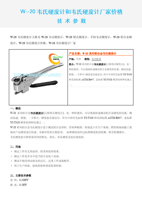
W-20韦氏硬度计和韦氏硬度计厂家价格技术参数W-20韦氏硬度计又称为W-20韦式硬度计,W-20钳式硬度计,手持韦式硬度计,W-20铝合金硬度计,W-20韦氏硬度计价格,W-20韦氏硬度计厂家产品名称:W-20系列铝合金韦氏硬度计∙产地:中国销售:沧州欧谱∙简介:W-20系列铝合金韦氏硬度计(又称钳式硬度计),是一种轻便的,可以现场快速测试铝合金硬度的仪器。
测试迅速,简便,一卡即可,硬度值直接读出,符合中国有色标准YS/T420和美国标准ASTM B647,是标准YS/T420推荐的两种仪器之一。
一、概述W-20系列铝合金韦氏硬度计(又称钳式硬度计),是一种轻便的,可以现场快速测试铝合金硬度的仪器。
测试迅速,简便,一卡即可,硬度值直接读出,符合中国有色标准YS/T420和美国标准ASTM B647,是标准YS/T420推荐的两种仪器之一。
W-20系列铝合金韦氏硬度计适于测试铝合金型材、管材和板材,特别适于在生产现场、销售现场或施工现场对产品硬度进行快速、非破坏性的合格检查。
标准硬度块经过标准硬度机的检测,附有检测报告。
韦氏硬度值可换算成常用的维氏、洛氏、布氏硬度及抗拉强度值。
二、用途·确定工件有无热处理,检查热处理效果。
·确定工件是否为不适当的合金加工而成。
·测试不便送到实验室的过长、过重工件或装配件。
·用于生产检验、验收检验和质量监督检验。
三、主要技术参数量程:0-20HW精度:0.5HW测量范围:相当于20~110HRE四、标准配置主机:----------1台标准硬度块:----1块备用压针:------1支校正扳手:------1个小螺丝刀:-----1个仪器箱:--------1个可选附件压针标准硬度块感谢以下网站对本资料的大力支持:测厚仪 超声波测厚仪钢板测厚仪 金属测厚仪管道测厚仪 钢管测厚仪厚度测量仪 超声测厚仪高温测厚仪 壁厚测量仪覆层测厚仪 膜厚仪涂层测厚仪 镀层测厚仪油漆测厚仪 漆膜测厚仪锌层测厚仪 防腐层测厚仪麦考特测厚仪 尼克斯测厚仪磁感应测厚仪 涡流测厚仪膜厚测试仪 覆层测厚仪 电镀层测厚仪 涂镀层测厚仪镀锌层测厚仪 电解测厚仪氧化膜测厚仪 磁性测厚仪干膜测厚仪 湿膜测厚仪镀铬测厚仪 超声波探伤仪 超声波探伤仪 超声探伤仪数字超声波探伤仪 电火花检测仪焊缝探伤仪 超声波探伤仪 金属探伤仪 便携式探伤仪 钢结构探伤仪 磁粉探伤仪邵氏硬度计 橡胶硬度计便携式硬度计 便携式硬度计尼克斯测厚仪 里氏硬度计轧辊硬度计 巴氏硬度计韦氏硬度计 w-20韦氏硬度计模具硬度计 超声波硬度计洛氏硬度计 金属硬度计硬度测试仪 布氏硬度计肖氏硬度计 铸件硬度计轧辊硬度计 硬度仪钢板硬度计 铝合金硬度计电火花检测仪 电火花检漏仪电火花检测仪 漆膜划格器表面粗糙度仪 粗糙度测量仪粗糙度测试仪 喷砂粗糙度仪光洁度仪 便携式粗糙度仪粗糙度仪 附着力测试仪百格刀测试 百格刀 LED观片灯 黑白密度计光泽度仪 特价机票无损检测资源网 无损检测仪器无损123 网站目录标线测厚仪 硬度计超声波测厚仪 涂层测厚仪硬度计http://www.yingduji.top 无损检测http://www.wusunjiance.top探伤仪http://www.tanshangyi.top 硬度计测厚仪http://www.cehouyi.top 布氏硬度计洛氏硬度计 便携硬度计钢管硬度计 磷化膜测厚仪934-1巴氏硬度计 钢轨探伤仪lx-a邵氏硬度计 邵氏橡胶硬度计 涂层测厚仪 防腐层检测仪橡胶硬度计 工业观片灯油漆测厚仪 粗糙度检测仪。
WNK5系列智能压力变送器

WNK5 系列压力变送器是合肥皖科智能技术有限公司压力变送器系列仪表中的高性能产品。
他将采集的压力、差压、液位等物理信号,通过采集单元传感器和数字处理电路转化为标准信号。
变送器采用先进的专用集成电路数字技术,以实现最好的精度和信号的一致性。
每台变送器均在工厂进行环境温度特性化补偿,从而保证在很宽的工作温度范围内变送器精度最高,飘移最小。
精确、稳定、可靠。
应用WNK5 系列压力变送器可用于解决以下测量问题:各种过程控制领域中气体、蒸汽或液体的绝压、表压和差压测量;液体液位、体积或质量测量;与检测元件配套测量气体、蒸汽和液体的流量(体积流量和质量流量);耐高温,带膜片密封的条件下最高温度可达280℃;最高压力可达700bar。
特点精确、稳定、可靠;一流的性能,精度高达0.075%;长期稳定性高;量程比100:1;模块化设计、可更换电子模块和显示单元无需标定;菜单化人机界面操作,中英文语言切换简单易用;支持出厂数据恢复;有HART、PROFIBUS-PA、或FF 通信协议。
规格性能规格基准精度声明的基准精度包括线性精度、迟滞性和重复性。
长期稳定性动态性能每6.9MPa (1000psi )的静压影响每 10℃的环境温度影响安装位置影响供电电源电源影响每伏电压变化时,其零点和量程的变化应不超过校准量程±0.005% 振动影响按GB/T1827.3/IEC61298-3 测试,<0.1%量程上限量程与传感器限值电磁兼容环境Array输出重量温度限制0-100%相对湿度启动时间变送器通电后,启动时间短于2.0 秒启动时间用户可在0.0 至60 秒范围内输入对阶跃输入变化的模拟输出响应,作为一个时间常数。
此软件阻尼不包括传感器模块的响应时间。
尺寸图WNK51、59 压力变送器分解图WNK51、59 压力变送器尺寸图带显示整机尺寸图(单位mm)不带显示整机尺寸图(单位mm)WNK50、55 差压变送器分解图WNK50、55 差压变送器尺寸图带显示整机尺寸图(单位mm)不带显示整机尺寸图(单位mm)WNK5 系列压力变送器安装图------------------------------------------------------------------------------------------------------------------ WNK51、59 压力变送器安装图(单位mm)WNK50、55、57、58 差压变送器安装图(单位。
工程精灵205说明书
前言关于工程精灵工程精灵〔Engineering Genius 2005〕是南方“测绘通〞软件系列的产品之一。
它基于掌上电脑〔PDA〕,面向工程测量现场,为工放样、曲线测设、纵横断面测量、土石方计算、坐标转换、导线测量、水准测量测量等工作提供数据采集、数据计算、图形绘制的手段与工具。
是为工程测量技术人员量身定制的可视化程度极高的数据工具。
关于本手册本手册对工程精灵的安装、使用方法及有关技巧进行了详细的介绍。
用户应该仔细阅读,并边读边用,以求到达软件的最正确使用效果。
本手册版权归南方测绘仪器公司。
在著作权保护的范围内,未经本公司书面同意,禁止对其进行翻印、改编等行为。
关于PDA产品本身的使用问题,用户可直接阅读PDA产品的使用说明书。
本手册不提供这方面的详细资料。
版权及注册商标AutoCAD、Arc/Info、MapInfo、WinCE、Nikon、Leica、Geodimeter、Sokkia、Topcon、Pentax、清华山维等分别为软、硬件产品和相关公司的专用名称或注册商标,本手册仅为引用。
本公司相关产品作为政府信息产业部门认定的软件企业,南方测绘仪器公司一直致力于以测绘为中心的地理信息采集、成图及管理软件的开发与方案提供。
目前,公司的主要软件产品有:CASS6.0是本公司开发的数字化地形地籍成图软件。
CASS6.0是CASS的最新升级版本。
CLC为本公司开发的基于MapINFO平台的地籍信息管理专用软件,已在土地行业得到了广泛的应用。
SHIS是本公司开发的集测绘采集、面积分摊、信息管理、房产成图、房产打印等功能于一体的房产信息系统。
该产品已广泛应用于房产测绘与管理部门。
Casscan为本公司的地图扫描矢量化专用软件,主要用于栅格地图的矢量化处理,是已有白纸地图进入GIS的必备软件,它与CASS具有完美的结合。
平差易〔PA 2005〕是本公司开发的测绘数据平差处理软件,具有方便、易用的特点。
LM205中文资料

TL H 7755LM105 LM205 LM305 LM305A LM376Voltage RegulatorsJanuary 1995LM105 LM205 LM305 LM305A LM376Voltage RegulatorsGeneral DescriptionThe LM105series are positive voltage regulators similar to the LM100 except that an extra gain stage has been added for improved regulation A redesign of the biasing circuitry removes any minimum load current requirement and at the same time reduces standby current drain permitting higher voltage operation They are direct plug-in replacements for the LM100in both linear and switching regulator circuits with output voltages greater than 4 5V Important character-istics of the circuits areY Output voltage adjustable from 4 5V to 40VY Output currents in excess of 10A possible by adding external transistorsY Load regulation better than 0 1% full load with current limitingY DC line regulation guaranteed at 0 03% V YRipple rejection on 0 01%VY 45mA output current without external pass transistor (LM305A)Like the LM100 they also feature fast response to both load and line transients freedom from oscillations with varying resistive and reactive loads and the ability to start reliably on any load within rating The circuits are built on a single sili-con chip and are supplied in a TO-99metal canThe LM105is specified for operation for b 55 C s T A s a 125 C and the LM305 LM305A is specified for 0 C s T A s a 70 CSchematic and Connection DiagramsTL H 7755–1Metal Can PackageTL H 7755–3Top ViewOrder Number LM105H LM105H 883 SMD 5962-8958801 LM305H or LM305AHSee NS Package Number H08CC 1995National Semiconductor Corporation RRD-B30M115 Printed in U S AAbsolute Maximum RatingsIf Military Aerospace specified devices are required please contact the National Semiconductor Sales Office Distributors for availability and specifications(Note5)LM105LM305LM305A Input Voltage50V40V50VInput-Output Differential40V40V40V Power Dissipation(Note1)800mW800mW800mW Operating Temperature Range b55 C to a125 C b0 C to a70 C0 C to a70 C Storage Temperature Range b65 C to a150 C b65 C to a150 C b65 C to a150 C Lead Temperature(Soldering 10seconds)300 C300 C300 C Electrical Characteristics(Note2)Parameter ConditionsLM105LM305LM305AUnits Min Typ Max Min Typ Max Min Typ MaxInput Voltage Range8 5508 5408 550VOutput Voltage Range4 5404 5304 540VInput-Output Voltage3 0303 0303 030V DifferentialLoad Regulation R SC e10X T A e25 C0 020 050 020 05% (Note3)RSC e10X T A e T A(MAX)0 030 10 030 1%R SC e10X T A e T A(MIN)0 030 10 030 1%0s I O s12mA0s I O s12mAR SC e0X T A e25 C0 020 2%R SC e0X T A e70 C0 030 4%R SC e0X T A e0 C0 030 4%0s I O s45mALine Regulation T A e25 C% V0 C s T A s a70 C% VV IN b V OUT s5V T A e25 C0 0250 060 0250 060 0250 06% VV IN b V OUT t5V T A e25 C0 0150 030 0150 030 0150 03% V Temperature Stability T A(MIN)s T A s T A(MAX)0 31 00 31 00 31 0%2Electrical Characteristics(Note2)(Continued)Parameter ConditionsLM105LM305LM305AUnits Min Typ Max Min Typ Max Min Typ MaxFeedback Sense Voltage1 631 71 811 631 71 811 551 71 85VOutput Noise Voltage10Hz s f s10kHzC REF e00 0050 0050 005%C REF e0 1m F0 0020 0020 002%Standby Current Drain V IN e30V T A e25 C mA V IN e40V0 82 0mAV IN e50V0 82 00 82 0mACurrent Limit T A e25 C R SC e10X225300375225300375225300375mV Sense Voltage V OUT e0V (Note4)Long Term Stability0 10 10 1%Ripple Rejection C REF e10m F f e120Hz0 0030 0030 003% Vi JA TO-99Board Mount230230230 C W in Still Airi JA TO-99Board Mount in929292 C W 400LF Min Air Flowi JC TO-99252525 C W Note1 The maximum junction temperature of the LM105and LM305A is150 C and the LM305is85 C For operation at elevated temperatures devices in the H08C package must be derated based on a thermal resistance of168 C W junction to ambient or25 C W junction to case Peak dissipations to1W are allowable providing the dissipation rating is not exceeded with the power average over a five second interval for the LM105and averaged over a two second interval for the LM305Note2 Unless otherwise specified these specifications apply for temperatures within the operating temperature range for input and output voltages within the range given and for a divider impedance seen by the feedback terminal of2k X Load and line regulation specifications are for a constant junction temperature Temperature drift effects must be taken into account separately when the unit is operating under conditions of high dissipationNote3 The output currents given as well as the load regulation can be increased by the addition of external transistors The improvement factor will be roughly equal to the composite current gain of the added transistorsNote4 With no external pass transistorNote5 Refer to RETS105X Drawing for military specifications for the LM1053Typical Performance Characteristics LM105 LM305 LM305ACurrent LimitingLoad Regulation Load Regulation CharacteristicsOptimum Divider Resistance Current Limit Sense Voltage Short Circuit Current ValuesMinimum Input Voltage Regulator Dropout Voltage Supply Voltage RejectionMinimum Output Voltage Standby Current Drain Transient ResponseTL H 7755–64Typical Applications10A Regulator with Foldback Current LimitingSolid tantalumElectrolyticTL H 7755–41 0A Regulator with Protective DiodesProtects against shorted input or inductive leads onunregulated supplyProtects against input voltage reversalProtects against output voltage reversalTL H 7755–5Linear Regulator with Foldback Current LimitingTL H 7755–8Current RegulatorTL H 7755–9 5Typical Applications (Continued)Shunt RegulatorTL H 7755–10Switching Regulator Solid tantaium125turns e 22on ArnoldEngineering A262123-2molybdenum permally core TL H 7755–11Basic Positive Regulator with Current LimitingTL H 7755–121 0A Regulator with Protective DiodesProtects against shortedinput or inductive loads on unregulated supply Protects against input voltage reversalProtects against outputvoltage reversalTL H 7755–13Linear Regulator with Foldback Current LimitingTL H 7755–1467L M 105 L M 205 L M 305 L M 305A L M 376V o l t a g e R e g u l a t o r sPhysical Dimensions inches (millimeters)Metal Can Package (H)Order Number LM105H LM105H 883 SMD 5962-8958801 LM305H or LM305AHNS Package Number H08CLIFE SUPPORT POLICYNATIONAL’S PRODUCTS ARE NOT AUTHORIZED FOR USE AS CRITICAL COMPONENTS IN LIFE SUPPORT DEVICES OR SYSTEMS WITHOUT THE EXPRESS WRITTEN APPROVAL OF THE PRESIDENT OF NATIONAL SEMICONDUCTOR CORPORATION As used herein 1 Life support devices or systems are devices or 2 A critical component is any component of a life systems which (a)are intended for surgical implant support device or system whose failure to perform can into the body or (b)support or sustain life and whose be reasonably expected to cause the failure of the life failure to perform when properly used in accordance support device or system or to affect its safety or with instructions for use provided in the labeling can effectivenessbe reasonably expected to result in a significant injury to the userNational Semiconductor National Semiconductor National Semiconductor National Semiconductor CorporationEuropeHong Kong LtdJapan Ltd1111West Bardin RoadFax (a 49)0-180-530858613th Floor Straight Block Tel 81-043-299-2309。
人民电器 JJW、JSW精密净化交流稳压器 产品说明书
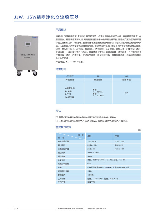
JJW 、JSW 精密净化交流稳压器产品概述精密净化交流稳压电源,它集净化稳压和滤波、抗干扰等多种功能于一体,具有稳压范围宽、响应速度快、稳压精度高等优点,并能有效地抑制各种噪声和尖峰干扰,是目前交流稳压电源产品中的优选机种,是614系列电子交流稳压电源磁饱和稳压电源以及补偿式稳压电源的理想换代产品。
人民集团系列精密净化交流稳压电源,以其优越的性能,满足了不同场合电器设施的需要,它主 要应用于以下几个领域:科研部门、大专院校、工矿企业、医疗卫生、广播台站、通讯、交通运输 、政府事业等各行各业,大量使用于微机及其周边装置、微机网络,各种医疗电子仪器设备、通讯 广播设备、交通信号系统、测试检验设备、各种数控机床、自动插件机等自动化生产设备。
产品符合: SJ /T 10541 标准。
选型指南□ 30kVA ;□ 三相:3kVA ;6kVA ;10kVA ;15kVA ;20kVA ;30kVA ;50kVA ;60kVA ;100kVA ;单相:1kVA ;2kVA ;3kVA ;5kVA ;10kVA ;15kVA ;20kVA ;规格表1主要技术数据037本稳压电源是以正弦能量分配器为核心,配以大容量滤波器和集成化控制电路而构成,主回路的工作原理大致如下图1和图2:净化电源电路原理图(此图仅供参考,如有修改,恕不另行通知)输入输出图1LNLNKC1BJL2L3L5C5C3L1FUSESCRZ C2R8IC3IC2C1R6R3VR1R1R2R5R7C3R11C9R15IC4+12V VINGNDR13C5C6C7C8B2L1C -1L3C -3R24B1L5C -2XOUTIN图2T1R10D1D2N9C4D7JXTST2T3R22R21WDR23R18D4D5T4图中K 为控制开关,控制着整个稳压电源的起停,C1-C3及L1-L3和可变阻抗“Z ”构成了有名的正弦能量分配电路。
L3或L2组成一自藕变压器T1,可变阻抗“Z ”由双向可控硅SCR 和电感L 组成,外加三次谐波滤波器L3、C3和五次谐波滤波器L5、C5。
SW205E-datasheet

SILKWORM 205E支持2 Gbit/sec速率的Brocade SilkWorm205E光纤通道交换机让中小型用户轻松部署和配置经济实用的SAN系统。
主要特性∙为入门级SAN提供了一个低成本、高灵活性的基础设备,也可作为“核心-边缘”SAN环境中的边缘交换机。
∙使用Brocade EZSwitchSetup安装向导,SAN的配置工作只需通过3个步骤和点击鼠标即可完成。
∙提供一般大型用户才具备的2 Gbit/sec性能和可用性水平。
∙可自动配置1、2 Gbit/sec,向后与现有Brocade SAN光纤网络兼容,保护投资。
∙增强资源使用,提高效率,改进业务运行水平。
具备优良扩展性能的低成本小型SAN随着数据容量和价值的不断增长,数据存储技术解决方案不仅要易于实施和便于管理,而且能在系统扩容和改动时将对业务的影响降至最低。
现在,Brocade® 的SAN解决方案就能很好地简化IT管理基础设施,缩小数据备份窗口,提高系统性能,并降低整体数据存储成本。
Brocade SilkWorm® 205E是速率为2 Gbit/sec的 8口光纤通道交换机,是理想的低成本的单交换机解决方案,非常适合用于新建小型SAN或对现有SAN进行技术升级。
为了便于新建用户部署SAN,SilkWorm 205E提供了EZSwitchSetup 简便安装向导,并增强了多项重要的使用和配置功能。
SilkWorm 205E以入门级的成本,却大大地提高了SAN的性能和功能。
由于采用了第五代博科通讯技术,SilkWorm 205E可自动感应1、2 Gbit/sec的光纤通道数据吞吐能力,同时还包括了多项可大大增强交换机运行性能的新功能。
因此,用户能够以较低的成本,享受到高性能SAN所带来的优势。
经济实用的扩展性针对中小型用户的需求,SilkWorm 205E在硬件和软件功能上具有多项创新的设计,使其能在多种IT 环境中轻松进行部署、集成和管理。
w-20韦氏硬度计说明书英文版

w-20韦氏硬度计说明书英文版W-20 Vickers Hardness Tester ManualIntroduction:The W-20 Vickers Hardness Tester is an advanced and reliable instrument used to measure the hardness of various materials. This manual serves as a comprehensive guide to operating and maintaining the W-20 Vickers Hardness Tester. It covers the necessary procedures for conducting hardness tests, interpreting the results, and ensuring the accuracy and longevity of the instrument.Safety Precautions:1. Before operating the W-20 Vickers Hardness Tester, carefully read and understand this manual.2. Always wear appropriate personal protective equipment (PPE), including safety glasses and gloves.3. Keep the work area clean and free from clutter to avoid accidents or damage to the instrument.4. Do not touch the indenter or test piece during the hardness test.5. Turn off the power and disconnect the power cord when not in use or during maintenance.Specifications:- Maximum Test Force: 20 kgf- Test Force Application Method: Automatic loading and unloading- Test Load Dwell Time: 0 - 60 seconds- Test Force Control: Closed-loop system- Test Force Accuracy: ±1%- Test Force Retention Time: 10 - 600 seconds- Indenter: Diamond Vickers- Magnification: 100x- Measuring Range: 8-2900 HV- Test Force Selection: Manual or automaticOperating Instructions:1. Power on the W-20 Vickers Hardness Tester and wait for the system to initialize.2. Select the desired test force and enter the value using the control panel.3. Clean the surface of the test piece and securely fix it onto the testing table.4. Position the indenter above the test piece, ensuring proper alignment.5. Initiate the loading cycle and wait for the test force to be applied.6. Once the dwell time is reached, the test force will be automatically removed.7. The hardness value will be displayed on the control panel, along with the measuring range.8. Record the hardness value and repeat the process for additional tests if necessary.Maintenance and Calibration:1. Regularly clean the indenter and test table with a lint-free cloth and a mild solvent.2. Inspect the indenter for any signs of wear or damage. Replace if necessary.3. Calibrate the W-20 Vickers Hardness Tester annually or as recommended by the manufacturer.4. Perform a calibration check using certified hardness test blocks.5. Follow the provided calibration procedure to ensure accurate hardness readings.6. Keep the instrument in a clean and dust-free environment when not in use.7. Never disassemble the W-20 Vickers Hardness Tester unless authorized by a qualified technician.Troubleshooting:Problem: Inaccurate hardness readings.Solution: Ensure proper calibration and follow the recommended testing procedures. Check the indenter for wear or damage.Problem: System malfunction or error messages.Solution: Restart the instrument and refer to the troubleshooting section of the manual. If the problem persists, contact technical support.Conclusion:The W-20 Vickers Hardness Tester is a reliable and precise instrument for measuring the hardness of materials. By following the instructions provided in this manual, users can effectively conduct hardness tests and maintain the accuracy and longevity of the instrument. For any technical issues or further assistance, please refer to the contact information provided in the manual.。
WDK 2020年9月版 - 电磁感应器产品说明书
Dimensions: [mm]Scale - 2,5:17447720068A74477200687447720068T e m p e r a t u r eT T T 7447720068Cautions and Warnings:The following conditions apply to all goods within the product series of WE-TI of Würth Elektronik eiSos GmbH & Co. KG:General:•This electronic component was designed and manufactured for use in general electronic equipment.•Würth Elektronik must be asked for written approval (following the PPAP procedure) before incorporating the components into any equipment in fields such as military, aerospace, aviation, nuclear control, submarine, transportation (automotive control, train control, ship control), transportation signal, disaster prevention, medical, public information network, etc. where higher safety and reliability are especially required and/or if there is the possibility of direct damage or human injury.•Electronic components that will be used in safety-critical or high-reliability applications, should be pre-evaluated by the customer. •The component is designed and manufactured to be used within the datasheet specified values. If the usage and operation conditions specified in the datasheet are not met, the wire insulation may be damaged or dissolved.•Do not drop or impact the components, the component may be damaged.•Würth Elektronik products are qualified according to international standards, which are listed in each product reliability report. Würth Elektronik does not warrant any customer qualified product characteristics beyond Würth Elektroniks’ specifications, for its validity and sustainability over time.•The customer is responsible for the functionality of their own products. All technical specifications for standard products also apply to customer specific products.Product specific:Soldering:•The solder profile must comply with the technical product specifications. All other profiles will void the warranty.•All other soldering methods are at the customers’ own risk.Cleaning and Washing:•Washing agents used during the production to clean the customer application might damage or change the characteristics of the wire insulation, marking or plating. Washing agents may have a negative effect on the long-term functionality of the product. Potting:•If the product is potted in the costumer application, the potting material might shrink or expand during and after hardening. Shrinking could lead to an incomplete seal, allowing contaminants into the core. Expansion could damage the components. We recommend a manual inspection after potting to avoid these effects. Storage Conditions:• A storage of Würth Elektronik products for longer than 12 months is not recommended. Within other effects, the terminals may suffer degradation, resulting in bad solderability. Therefore, all products shall be used within the period of 12 months based on the day of shipment.•Do not expose the components to direct sunlight.•The storage conditions in the original packaging are defined according to DIN EN 61760-2.•The storage conditions stated in the original packaging apply to the storage time and not to the transportation time of the components. Packaging:•The packaging specifications apply only to purchase orders comprising whole packaging units. If the ordered quantity exceeds or is lower than the specified packaging unit, packaging in accordance with the packaging specifications cannot be ensured. Handling:•Violation of the technical product specifications such as exceeding the nominal rated current will void the warranty.•Applying currents with audio-frequency signals might result in audible noise due to the magnetostrictive material properties. •Due to heavy weight of the components, strong forces and high accelerations might have the effect to damage the electrical connection or to harm the circuit board and will void the warranty.•Please be aware that products provided in bulk packaging may get bent and might lead to derivations from the mechanical manufacturing tolerances mentioned in our datasheet, which is not considered to be a material defect.•The temperature rise of the component must be taken into consideration. The operating temperature is comprised of ambient temperature and temperature rise of the component.The operating temperature of the component shall not exceed the maximum temperature specified.These cautions and warnings comply with the state of the scientific and technical knowledge and are believed to be accurate and reliable.However, no responsibility is assumed for inaccuracies or incompleteness.Würth Elektronik eiSos GmbH & Co. KGEMC & Inductive SolutionsMax-Eyth-Str. 174638 WaldenburgGermanyCHECKED REVISION DATE (YYYY-MM-DD)GENERAL TOLERANCE PROJECTIONMETHODTRi001.0012019-07-17DIN ISO 2768-1mDESCRIPTIONWE-TI Radial Leaded Wire WoundInductor ORDER CODE7447720068SIZE/TYPE BUSINESS UNIT STATUS PAGEImportant NotesThe following conditions apply to all goods within the product range of Würth Elektronik eiSos GmbH & Co. KG:1. General Customer ResponsibilitySome goods within the product range of Würth Elektronik eiSos GmbH & Co. KG contain statements regarding general suitability for certain application areas. These statements about suitability are based on our knowledge and experience of typical requirements concerning the areas, serve as general guidance and cannot be estimated as binding statements about the suitability for a customer application. The responsibility for the applicability and use in a particular customer design is always solely within the authority of the customer. Due to this fact it is up to the customer to evaluate, where appropriate to investigate and decide whether the device with the specific product characteristics described in the product specification is valid and suitable for the respective customer application or not.2. Customer Responsibility related to Specific, in particular Safety-Relevant ApplicationsIt has to be clearly pointed out that the possibility of a malfunction of electronic components or failure before the end of the usual lifetime cannot be completely eliminated in the current state of the art, even if the products are operated within the range of the specifications.In certain customer applications requiring a very high level of safety and especially in customer applications in which the malfunction or failure of an electronic component could endanger human life or health it must be ensured by most advanced technological aid of suitable design of the customer application that no injury or damage is caused to third parties in the event of malfunction or failure of an electronic component. Therefore, customer is cautioned to verify that data sheets are current before placing orders. The current data sheets can be downloaded at .3. Best Care and AttentionAny product-specific notes, cautions and warnings must be strictly observed. Any disregard will result in the loss of warranty.4. Customer Support for Product SpecificationsSome products within the product range may contain substances which are subject to restrictions in certain jurisdictions in order to serve specific technical requirements. Necessary information is available on request. In this case the field sales engineer or the internal sales person in charge should be contacted who will be happy to support in this matter.5. Product R&DDue to constant product improvement product specifications may change from time to time. As a standard reporting procedure of the Product Change Notification (PCN) according to the JEDEC-Standard inform about minor and major changes. In case of further queries regarding the PCN, the field sales engineer or the internal sales person in charge should be contacted. The basic responsibility of the customer as per Section 1 and 2 remains unaffected.6. Product Life CycleDue to technical progress and economical evaluation we also reserve the right to discontinue production and delivery of products. As a standard reporting procedure of the Product Termination Notification (PTN) according to the JEDEC-Standard we will inform at an early stage about inevitable product discontinuance. According to this we cannot guarantee that all products within our product range will always be available. Therefore it needs to be verified with the field sales engineer or the internal sales person in charge about the current product availability expectancy before or when the product for application design-in disposal is considered. The approach named above does not apply in the case of individual agreements deviating from the foregoing for customer-specific products.7. Property RightsAll the rights for contractual products produced by Würth Elektronik eiSos GmbH & Co. KG on the basis of ideas, development contracts as well as models or templates that are subject to copyright, patent or commercial protection supplied to the customer will remain with Würth Elektronik eiSos GmbH & Co. KG. Würth Elektronik eiSos GmbH & Co. KG does not warrant or represent that any license, either expressed or implied, is granted under any patent right, copyright, mask work right, or other intellectual property right relating to any combination, application, or process in which Würth Elektronik eiSos GmbH & Co. KG components or services are used.8. General Terms and ConditionsUnless otherwise agreed in individual contracts, all orders are subject to the current version of the “General Terms and Conditions of Würth Elektronik eiSos Group”, last version available at .Würth Elektronik eiSos GmbH & Co. KGEMC & Inductive SolutionsMax-Eyth-Str. 174638 WaldenburgGermanyCHECKED REVISION DATE (YYYY-MM-DD)GENERAL TOLERANCE PROJECTIONMETHODTRi001.0012019-07-17DIN ISO 2768-1mDESCRIPTIONWE-TI Radial Leaded Wire WoundInductor ORDER CODE7447720068SIZE/TYPE BUSINESS UNIT STATUS PAGE。
美菱冰箱 BCD-205WEBJC 使用说明书
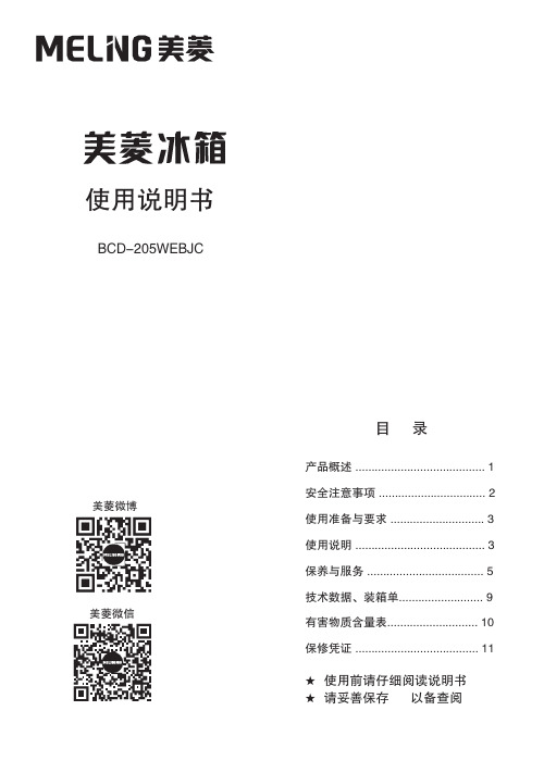
使用说明书★ ★ 使用前请仔细阅读说明书请妥善保存 以备查阅目 录美菱微信美菱微博BCD-205WEBJC产品概述 ........................................ 1安全注意事项 (2)使用准备与要求 ............................. 3使用说明 ........................................ 3保养与服务 .................................... 5技术数据、装箱单.. (9)有害物质含量表............................ 10保修凭证 .. (11)冰箱内装有高效ADF+净味抗菌模块,对储存的食品具有净味抗菌保鲜的功能。
该系列冰箱是无霜冷藏冷冻箱。
冰箱上部为冷藏室,可放置瓜果、蔬菜、蛋类、奶类等需要进行冷藏保鲜的食品;冰箱下部为冷冻室,可放置鱼类、肉类等需冻结存放的食品。
1产品概述冰箱结构简图本说明书中某些特征和装置的说明可能与您的冰箱不完全一致,请以实物为准。
瓶框尊敬的用户:感谢您选择、使用美菱冰箱!★ ★ 请遵守本说明书操作规程及注意事项。
★ 若冰箱出现故障,请勿自行拆卸修理或交由未经本公司授 权的维修部门修理,请拨打我公司的服务热线电话: 4008111666、4006111666,告之您的姓名、地址、电话、 冰箱型号、购机时间、故障现象等,我们将竭诚为您服务。
★ 由于产品的改进,您所购买的美菱冰箱可能与说明书中的 介绍不完全一致,谨此致歉。
为了您安全、方便地使用及合理地维护,请在使用前仔细 阅读本使用说明书,并妥善保存以备查看。
★本器具用于家用和类似用途,如:商店、办公室或其它工作场合的厨房区域; 农场以及宾馆、 汽车旅店和居住型环境的顾客; 家庭旅馆型环境;餐饮业和类似的非零售业应用。
★ 产品执行标准:GB/T 8059 GB 4706.1 GB 4706.13 GB 12021.2 GB 4343.1 GB 17625.1 GB 19606(注:以上标准最新版本适用于本产品。
HONEYWELL Wind Turbine WT6500 所有者手册说明书
HONEYWELL™ Wind TurbineModel WT6500Master Installer’s GuideThis manual is intended for the use of a licensed contractor. If you are alicensed and insured contractor who would like to become an AuthorizedInstaller, please send your request to Installer@.The HONEYWELL™ trademark is used under license from HoneywellInternational Inc.Honeywell International Inc. makes no representations, or warranties withrespect to this product or service.Safety InformationImportant Safety Instructions1. This Master Installer’s Guide contains important instructions for the HONEYWELL™ Wind Turbineinstallation and maintenance. Please save it.2. Read the entire Master Installer’s Guide prior to installation and follow all warnings and cautionsincluded on the Master Installer’s Guide and/or attached to the HONEYWELL™ Wind Turbine.3. Improper installation, adjustment, alteration, service maintenance, or use can cause fire, electricalshock, or other conditions which may cause death, personal injury or property damage.4. Choose a very calm, nearly no wind, day for the installation.5. Follow the installation procedures contained within this Guide and all safety codes. Follow theNational Electric Code (NEC) and your local building zoning codes. In Canada, follow the CanadianElectrical Code (CEC).6. Only licensed and trained personnel should move and lift the HONEYWELL™ Wind Turbine. Theturbine should only be moved using standard hoists and hydraulic lifts.7. Appropriate protective personal equipment such as hard hat, work gloves, safety glasses, andclosed toe work shoes should be worn when installing the HONEYWELL™ Wind Turbine.8. Only licensed and trained personnel can perform the following maintenance functions on thisHONEYWELL™ Wind Turbine:• Open and work on the SMARTBOX™ Controller• Open and work on the Junction Box at the turbine• Apply any torque to any of the turbine’s fasteners9. The installation directions include recommendations of a variety of options. These must beapproved and certified by your local Professional Engineer (PE). The installer must acquire all thenecessary permits from the local authorities prior to installation.The HONEYWELL™ Wind Turbine is manufactured by WindTronics. Please contact WindTronics at:621 Sprucewood AvenueWindsor, OntarioN9C 0B3877-946-3898The Honeywell Trademark is used under license from Honeywell International Inc.Honeywell International Inc. makes no representations or warranties with respect to this product.Manufacturer reserves the right, without notice or liability, to change design and specifications at anytime.Evaluation and Installation ListPermitsState:Permit#_______________ Date_____________County:Permit#_______________ Date_____________ City:Permit#_______________ Date_____________HOA: Permit#_______________ Date_____________Site evaluation (go to page #5 for requirements)Distance from Turbine to Smart Box (max 200 ft (60m))__________Height to center of Turbine______________________________Draw all obstructions on site mapDraw site map (view from above - use space below for your drawing)Prevailing wind directionLocation of:ObstaclesTurbineSmart BoxBattery enclosure (max 10ft (3m) from Smart Box)Mounting Hardware(choose one – see pages 5-10 for drawings - see Owner’s Manual for more details)Flat roof: QUADPOD™ Mount and Ballast (need drawing)Pitched roof: QUADPOD™ Mount and ROOFBOX™ MountPole: height____________ material_______________(example on page 7)Accessories(Supplied by Installer)Batteries: TWO-12V, 100Ah, flooded, deep cycle, marine grade batteries.Battery enclosure(2) Fused disconnects (see page #12)(1) Non-fused disconnect (see page #12)Sub panelConnection:¾” Conduit1” ConduitBattery terminal lugsCAT5E or CAT6 stranded cable#4 THWN - 2 red#4 THWN - 2 black#4 THWN - 2 green#6 THWN - 2 green#8 THWN - 2 black#8 THWN - 2 red#8 THWN - 2 white#10 THWN - 2 black#10 THWN - 2 white#10 THWN - 2 red#12 THWN - 2 greenUnpacking(refer to instructions in package)Smart Box: Serial #___________________Owner’s ManualTurbine crate:Turbine: Serial #____________________(2) Deflectors and mounting hardwareTurbine interface enclosureOwner’s ManualMount and Level Turbine– refer to lift point on page 10Assembly– refer to page 12 for wiring diagramCommissioning– follow menus on Smart Box display (refer to pages 14-15)Site SurveyPersonal Injury and Property Damage HazardImproper installation, alteration, service or maintenance may result in death,serious bodily injury or property damage. Installation or repairs made byunqualified persons could result in hazards to you and others. Installationmust conform with all safety and other codes of all governmental authoritieshaving jurisdiction.The information contained in this owners manual is intended for use bylicensed and trained professionals that are experienced in installing andservicing the HONEYWELL™ Wind Turbine, are familiar with all precautionsand safety procedures required in such work, and are equipped with theproper tools and machinery.When selecting the best location for the wind turbine, consider the following:1. Wind – is the area windy enough to support the installation of a wind turbine?2. Height – install as high as possible. Ideally, the height should be greater than 33’.3. Obstructions – place the turbine in the location furthest away from all obstacles (buildings, trees,parapits, HVAC units, rooftops, etc.)4. Prevailing Wind – as a general guide, place the turbine in a location that can best take advantage ofprevailing winds (if you do not know, you can find historical “wind rose” information on the Internet).IMPORTANT: PLEASE TAKE NOTEIf the prevailing wind has to travel across a rooftop before passing through the turbine it will be lesseffective than if the turbine was placed where the wind would come into contact with the turbine first. Mounting OptionsPersonal Injury and Property Damage HazardDo not install the HONEYWELL™ Wind Turbine in a location that isaccessible to children or pets. Failure to follow this warning may result indeath, personal injury or property damage.Personal Injury and Property Damage HazardThe HONEYWELL™ Wind Turbine must be mounted by licensed andtrained personnel only, with the use of all appropriate hardware. Failure tofollow this warning could cause the HONEYWELL™ Wind TurbineWhichever mounting option is chosen should be approved by a local ProfessionalEngineer (PE). All of the options listed have been rated by our Professional Engineer.Please refer to the following designs and their included specifications.Failure to follow proper installation practices for any of themounting options could result in death, serious injury and/or property damage.WHEN MOUNTING ON OR OVER A COMBUSTIBLE SURFACE, A FLOOR PLATE OF AT LEAST 1.43 mm GAL-VANIZED OR 1.6 mm UNCOATED STEEL EXTENDED AT LEAST 150 mm BEYOND THE EQUIPMENT ON ALL SIDES MUST BE INSTALLED.Ballast MountFigure 1 Ballast MountPoleMountFigure 2 Pole MountROOFBOX™ Mount Extended QUADPOD™ MountFigure 4ROOFBOX™ with QUADPOD™ MountingLift PointLift Point: The recommended lift point is shown in the photograph below:WiringELECTRIC SHOCK HAZARDDisconnect turbine and battery circuits before wiring. Turn off allpower before wiring. Failure to follow safety warning could result inserious injury and/or death.PROFESSIONAL INSTALLATION requiredInstallations must meet all local electrical codes. Installations for the equipment shouldonly be performed by a qualified electrician or a licensed and trained WindTronicsinstaller.The wiring connections between a mounted HONEYWELL™ Wind Turbine, BatteryBox and SMARTBOX™ Controller is relatively simple. The following diagram detailsand specifies the wire gauges required in this installation. It is strongly recommendedthat a certified and trained electrician performs all the electrical connection. Allelectrical systems must be grounded in accordance to the National Electric Code(NEC) (or, in Canada, the Canadian Electric Code (CEC)) and local standards. Pleaserefer to the SMARTBOX™ Controller Manual for full details on wiring, connecting andcommissioning of the HONEYWELL™ Wind Turbine.Illustration of Turbine System ConnectionsFigure 5 System ConnectionJunction BoxPurpose: Interface between the turbine and the SMARTBOX™ Controller which houses the safetybraking circuitry to limit the maximum turbine speed. The cylinder attached to the junction box housesthe resistor used to brake the turbine and dissipate excess energy as heat. The anemometer sendswind speed and direction signals to the SMARTBOX™ Controller.Mounting: The junction box comes hard wired to the turbine. It should be mounted high enough off the ground to ensure the anemometer will be able to function through all seasons (i.e. will not be coveredwith snow in the winter). The junction box can be mounted through two pre-drilled holes in the blackbars on the back of the junction box. The QUADPOD™ Mount has pre-drilled holes for mounting ofthe junction box. Mounting hardware is supplied by the Installer.Figure 7Junction Box EnclosureCommissioningEXPLOSION OR FIRE HAZARDEntering battery information incorrectly may result in explosion or fire.During commissioning, the controller and turbine must be setup. In the controller, very importantsystem information such as the battery type, number of battery banks and battery capacity must besetup. Ensure you have this system information prior to commissioning.See the SMARTBOX™Controller Manual for proper set up.In addition to controller setup, the turbine’s components will also need to be tested. This testing can be done via the controller’s display.The following is the proper procedure to commission the HONEYWELL™ Wind Turbine. Do notproceed with commissioning until ALL DISCONNECTS are in the OFF position and the turbine bladesrotate freely.1. Check all connections for polarity.2. Apply the battery power to the unit with the disconnect or selector switch inside the battery enclosure.3. The LCD display will light up and prompt a display:Display DescriptionWINDTRONICS RX.XX FIRST POWER UP The SMARTBOX™ will display this for 5 seconds and then move to the required setup information.4. The system will automatically walk you through the commissioning process. All steps must becompleted before the turbine will operate. If problems are found during this process, you can turn off the battery disconnect at any time to restart the power up process. All of the settings will be saved, but you must start over and step through all the steps until complete.For optimal performance it is IMPORTANT to enter OPTIMAL battery information (steps 5-7).We highly recommend using two 12V deep cycle/flooded/marine 100Ahr batteries. For this selection please enter the following optimal settings for best performance.5. At the first prompt screen, select the battery type by using the arrow keys. Press ENTER whenfinished.Display Description OptimalENTER BATTERY TYPEFLOODED Set the battery type Enter FLOODED forflooded battery6. Select the battery Amp hour rating for ONE battery by using the arrow keys. Press ENTER whenfinished.Display Description OptimalENTER BATTERY AHr100Set the battery Amp hour rating for ONEbatteryEnter 140 for100Ahr battery7. Select the number of battery banks in parallel by using the arrow keys.Press ENTER when finished.Display Description OptimalENTER BATTERYBANKS1Set the number of battery banks Enter 3 for one bank of2-12V batteries8. At this point the batteries are all set up. Now we will move to the turbine setup and check itscomponents for operation. This requires two people: one at the turbine and one at the SMARTBOX™ Controller.9. Testing the turbine: Turn on the turbine disconnect.10. Observe Turbine Blades:• If turbine blades are rotating and display reads GREATER than 0V, press ENTER to continue.• If turbine blades are rotating and display reads 0V, turn off battery disconnect, check wiring, and restart commissioning process.[NOTE: If wind is not causing turbine wheel to spin, gently spin the wheel by hand to determine if the Smart Box is detecting a voltage.]Display DescriptionTURBINE INPUTOKShows if a turbine voltage was found.11. Testing the AC grid connection: Turn on the AC disconnect from the Grid input.12. Check the display and make sure the AC voltage is OK. Range should be 110V ±5% (or 220V ±10%). Ifthere is no grid connection, press ENTER to skip.Display DescriptionAC Grid 120V OK?? (or 230V OK??)Checks the AC voltage.Press ENTER to skip if there is no grid connection or if voltage is within range. If not within range,re-start commissioning.13. Test AC load connection: Turn on AC disconnect to the load. Turn on all items on the sub panel load tomake sure turbine inverter can handle the load.14. The system commissioning is now complete. Press ENTER to start the turbine. In the technician menu,you can force this process over again if required.Display DescriptionCOMMISSIONCOMPLETEPress ENTER to Start the Turbine.Manufacturer reserves the right, without notice or liability, to change design and specifications at any time.The Honeywell Trademark is used under licensefrom Honeywell International Inc.and makes no representations or warranties with respect to this product. WindTronicsHoneywell International Inc.621 Sprucewood AvenueWindsor, Ontario N9C 0B3Tell: 877-946-3898。
干冰发烟机技术参数
干冰发烟机技术参数
干冰发烟机是一种利用干冰与水接触产生烟雾效果的设备。
其
技术参数包括以下几个方面:
1. 功率,干冰发烟机的功率通常以瓦特(W)为单位,表示设
备的电力消耗能力。
2. 容量,指干冰发烟机能够容纳的干冰量,通常以千克(kg)
为单位。
3. 出烟量,描述干冰发烟机单位时间内产生的烟雾量,常以立
方米/分钟(m³/min)或升/秒(L/s)为单位。
4. 加热时间,指干冰发烟机从启动到达到最佳工作状态所需的
时间,通常以分钟为单位。
5. 控制方式,描述干冰发烟机的操作控制方式,包括手动控制、遥控操作或自动控制等。
6. 尺寸和重量,描述干冰发烟机的外形尺寸和重量,以便于安
装和搬运。
7. 使用环境,包括工作温度、湿度要求等,以及适用的场景和环境。
在选择干冰发烟机时,需要根据实际需求综合考虑以上技术参数,以确保设备能够满足使用要求。
同时,不同厂家生产的干冰发烟机技术参数可能会有所差异,因此在选购设备时还需要对比不同产品的参数,选择最适合自己需求的干冰发烟机。
Daikin 水冷冷却机和远热源冷却机产品介绍说明书

EWWD120-540MBYN EWLD120-540MBYNApplied systemsWater-cooled chillers Remote condenser chillersNEWw w w .d a i k i n e u r o p e .c o mFlexible applicationDaikin’s unique position as a manufacturer of air conditioning equipment,compressors and refrigerants has led to its close involvement in environmental issues.For several years Daikin has had the intention to become a leader in theprovision of environmental friendly products. This challenge demands the eco design and development of a wide range of products and an energy management system;which involves energy conservation and reduction of waste.•flow switch standard supplied with the unit•water filter with diameter perforations of 1mm supplied as standard accessory •Standard fitted with victaulic joints on evaporator:-Victualic joints absorb vibrations, reduce operating sound and thermal deflection and simplify chiller piping and installation-They can accommodate 8°angles and guarantee stress free, leak tight water piping connection.Easy installationLeaving water condenser°CLeaving Water Evaporator (°C)Pull-down areaContinuous operation areaWaterGlycol60504030201044-10410162030•9 models available with cooling capacities ranging from 123 to 546kW and heating capacities from 147 to 655kW•ideal for use in severe weather conditions and over a wide operation range.•2 independent circuits from 360kW onwards•remote condenser version available (EWLD120-540MBY)•compact, simple and robust construction•extended operation range from 50°C to 60°CA range to rely on.The new large Daikin chillers are fitted with a G-type single screw compressor with stepless capacity control. The G-type stepless single screw compressor enables capacity requirements to be closely matched by modulating the sliding valve position according to the chilled water control condition. Main advantages of continuous modulation are better part load efficiency and more stable chilled water temperatures with closer control tolerance. Capacity control is infinitely variable between 30% and 100% on single circuit units and between 15% and 100% on dual circuit units.Single screw compressorElectronic control•advanced pco 2control•detailed information on and accurate control of all functional parameters by easy menu scrolling: schedule timer, floating set point, free cooling, double evaporator pump, manual pump on,date and time information, daily pump on.•chilled water and brine temperatures down to -10°C on standardunit. (Parameter in the service menu of the DDC controller must be set by the installer)•changeable digital input/output such as remote on/off, remote cooling/heating, dual setpoint and limit capacity.•self diagnostic and can be set up in several languages.•Lead lag function is standard•standard equipped with night setback and peak load limitation.•optional digital controller can be installed up to 600 m from the unit.•remote DDC (EKRUPC) can be installed up to 1,000m from the unit•thanks to the standard DICN, simultaneous operation of up to 4 chillers is allowed.This function enables a Daikin 2MW chiller plant to be operated via a single controller.NEWSHELL & TUBE CONDENSER•special header distribution system and design of water system results in high efficiency and reduced heat transfer surface•compact dimensions and lower weight result in a smaller refrigerant volume.BPHE EVAPORATOR•brazed plate heat exchanger made of stainless steel plate, brazed gas tight with copper•optimised distribution benefits of R-134a•the use of this plate heat exchanger results in a compact units: single and double circuits have the same small footprint (2,672mm x 898mm)Heat exchangerNote: 1. For refrigerant charge of EWLD-MBY , please consult the databookNOTE: 1. For refrigerant charge of EWLD-MBY , please consult the databookNominal capacitycooling (EWWD)kW cooling (EWLD)kW heating (EWWD)kW Nominal inputcooling (EWWD)kW cooling (EWLD)kW heating (EWWD)kWEER EWWD/EWLD COP Capacity steps %Refrigerant circuittype charge (1)kg control oil type oil chargel Compressor type No. of circuits/compressors Dimensionsmm Machine weight (EWWD/EWLD)kg Sound power level standard /low noise option dB(A)Casing Piping connectionsevaporator water in/outlet evaporator water drain condenser water in/outlet condenser water drain relief device outletOperation range leaving water condenser °C EWWD/EWLD condensing temperature °C leaving water evaporator°C Power supplyYN EWWD-MBYN/EWLD-MBYN120/120180/170240/240280/26012318324927311617023526514721629032728.745.261.669.232.049.866.577.934.554.072.883.44.29/3.63 4.05/3.41 4.04/3.53 3.95/3.404.2643.983.9230 ~ 100R-134a18353738thermostatic expansion valveelectronic expansion valveFVC68D7.5101014Semi-hermetic single screw compressor1/11,014 x 2,672 x 898993 / 8841,263 / 1,1001,515 / 1,3321,613 / 1,41887/8193/8794/8893/87Polyester painted galvanised steel plate / Ivory white - Munsell 5Y7.5/13"OD3" victaulicfield installation2" 1/2 victaulic 3" victaulicM61 x 1"2 x 1"20°C ~ 50°C / 25°C ~ 55°C20°C ~ 50°C / 25°C ~ 55°C20°C ~ 60°C / 25°C ~ 62°C 20°C ~ 60°C / 25°C ~ 62°C25°C ~ 55°C -10°C ~ 20°C 3~/50Hz/400VEWWD-MBYN/EWLD-MBYNNominal capacitycooling (EWWD)kW cooling (EWLD)kW heating (EWWD)kW Nominal inputcooling (EWWD)kW cooling (EWLD)kW heating (EWWD)kWEER (EWWD/EWLD)COPCapacity steps %Refrigerant circuit typecharge (1)kgcontrol oil typeoil chargelCompressor type No. of circuits/compressors Dimensionsmm Machine weight (EWWD/EWLD)kg Sound power level standart/Low Noise option dB(A)Casingmaterial / colour Piping connectionsevaporator water in/outlet evaporator water drain condenser water inlet/outlet condenser water drain relief device outletOperation range leaving water condenser °C EWWD/EWLD condensing temperature °C leaving water evaporator°C Power supplyYN360/340440/400500/480520/500540/5403664324985225463404054705005304305055806176558910712713113898.4116133144156106.91271461561674.11/3.46 4.04/3.49 3.92/3.53 3.98/3.47 3.96/3.404.023.98 3.97 3.963.9230 ~ 10015 ~ 100R-134a70727475762 x thermostatic expansion valve1x thermost. exp. val v e+1x el e ctr. exp. val v eelectronic expansion valveFVC68D102 x 10 2 x 10¹⁰ + 14 2 x 14Semi-hermetic single screw compressor2/22,000 x 2,672 x 8982,526 / 2,2002,778 / 2,4323,030 / 2,6643,128 / 2,7503,326 / 2,83696/9096/9096/9096/9096/90Polyester painted galvanised steel plate / Ivory white - Munsell 5Y7.5/13" victaulic field installation 3" victaulic M62 x 1"3 x 1"4 x 1"20°C ~ 50°C / 25°C ~ 55°C20°C ~ 50°C / 25°C ~ 55°C20°C ~ 60°C / 25°C ~ 62°C20°C ~ 60°C25°C ~ 62°C25°C ~ 55°C -10°C ~ 20°C 3~/50Hz/400VOption Number Option description Completely combinable optionsop03dual pressure relief valve on the condenser (EWWD) op12suction stop valveop52main isolator switchop57a-meter, V-meterOPLN low noise operationAvailable kitsEKCLWS Leaving water controlsensor for DICN EKAC200A BMS cardEKBMSMBA BMS gateway modbus / j-bus protocol EKBMSBNA BMS gateway bacnet protocol EKRUPC Remote user interfaceTo install EKBMSMBA, EKBMSBNA --> EKAC200A needs to be installed on the unit(S) Option required for Swedish national law SNFS 1992 : 16120180/170240280/260360/340440/400500/480520540o (S)o (S)o (S)o (S)o (S)o (S)o (S)o (S)o (S)factory mounted o o o o o o o o o factory mounted o o o o o o o o o factory mounted o o o o o o o o o factory mounted o o o o o o o o o factory mountedo o o o o o o o o kito o o o o o o o o kito o o o o o o o o kito o o o o o o o o kito o o o o o o o o kito availableunit sizeAvailability1. Nominal cooling capacities are based on: evaporator: 12°C/7°C - condenser: 30°C/35°C (EWWD); condensing temperature: 45°C (EWLD) - liquid temperature: 40°C (EWLD)2. Nominal heating capacities are based on: evaporator: 12°C/7°C - condenser: 40°C/45°C3. The sound power level is an absolute value indicating the "power" which a sound source generates. Measuring conditionsE P L E 05-51 / 685 / 05/06 / L a M o v i d a P r i n t e d o n n o n -c h l o r i n a t e d p a p e r / P r i n t e d i n B e l g i umZandvoordestraat 300B-8400 Oostende, Belgium “The present leaflet is drawn up by way of information only and does not constitute an offer binding upon Daikin Europe N.V ..Daikin Europe N.V . has compiled the content of this leaflet to the best of its knowledge. No express or implied warranty is given for the completeness, accuracy, reliability or fitness for particular purpose of its content and the products and services presented therein. Specifications are subject to change without prior notice. Daikin Europe N.V . explicitly rejects any liability for any direct or indirect damage, in the broadest sense, arising from or related to the use and/or interpretation of this leaflet.All content is copyrighted by Daikin Europe N.V ..”Daikin Europe N.V. is approved by LRQA for its Quality Management System in accordance with the ISO9001 standard.ISO9001 pertains to quality assurance regarding design, development, manufacturing as well as to services related to the product.ISO14001 assures an effective environmental management system in order to help protect human health and the environment from the potential impact of our activities, products and services and to assist in maintaining and improving the quality of the environment.Daikin units comply with the European regulations that guarantee the safety of the product.Daikin Europe NV participates in the Eurovent Certification Programme for Air Conditioners (AC),Liquid Chilling Packages (LCP) and Fan Coil Units (FC); the certified data of certified models are listed in the Eurovent Directory.。
快克205焊台使用说明书
Lead Free Soldering Station 大型智能无铅电焊台高周波发热极速回温操作手册感谢您购买我们的无铅电焊台,本产品是专为无铅焊接而设计的,使用前请仔细阅读本说明书,阅读后请妥为保管,以便日后查阅。
目录注意事项……………………………………………………………………… 部件名称……………………………………………………………………… 装置和使用电焊台…………………………………………………………… 参数…………………………………………………………………………… 休眠……………………………………………………………………………选择合适的烙铁头来适应焊接要求………………………………………… 校准烙铁温度………………………………………………………………… 烙铁头的使用………………………………………………………………… 烙铁头的保养………………………………………………………………… 错误标记……………………………………………………………………… 排除故障指南………………………………………………………………… 如何检查发热器及传感器元件……………………………………………… 更换保险丝…………………………………………………………………… 规格…………………………………………………………………………… 烙铁头…………………………………………………………………………注意事项△!警告本使用说明书之“警告”和“注意”的定义如下:△!警告:滥用可能导致使用者死亡或重伤△!注意:滥用可能导致使用者受伤或对涉及物体造成实质破坏。
△!注意当电源接通时,烙铁头温度处于高温状态。
鉴于滥用可能导致灼伤或火患,请严格遵守以下事项:● 请避免本焊台的滥用,应按照操作说明使用本品。
● 切勿触及烙铁头附近的金属部份。
● 切勿在易燃物体附近使用烙铁头。
● 通知工场其他人士,烙铁头极易灼伤,可能引起危险事故。
休息时或完工后应关掉电源。
5欧20w限流电阻

5欧20w限流电阻限流电阻是一种用于限制电流流动的电子元件。
它的作用是通过阻碍电流的流动,使电路中的电流保持在一个可控范围内,以防止电路过载或损坏。
在电子设备中,限流电阻起到了重要的作用,尤其在大功率电路中更是必不可少的元件之一。
本文将介绍一种常见的限流电阻——5欧20w限流电阻。
5欧20w限流电阻的命名中,“5欧”表示其阻值为5欧姆,“20w”则表示其功率为20瓦特。
阻值是限流电阻的一项重要参数,它决定了电流在电路中的流动情况。
当电路中的电压施加在限流电阻上时,根据欧姆定律,电流的大小可以通过电压和阻值的比值来计算。
对于5欧20w限流电阻来说,当电压为1伏时,电流大小为0.2安培。
限流电阻的功率也是一个重要的参数。
功率表示单位时间内电阻所消耗的能量,它与电流和电压之间的关系可以通过功率公式来计算。
对于5欧20w限流电阻来说,当电流为0.2安培时,电压为2伏,根据功率公式可得到功率为20瓦特。
因此,这个限流电阻可以承受最大20瓦特的功率消耗。
5欧20w限流电阻通常由金属丝或者碳膜组成。
金属丝限流电阻的特点是阻值比较稳定,而碳膜限流电阻则具有体积小、重量轻的优点。
根据具体的应用需求,可以选择适合的限流电阻类型。
在实际应用中,5欧20w限流电阻被广泛应用于各种电子设备中。
例如,在电源电路中,限流电阻可以用来限制电流的大小,保护其他电子元件不受过电流的损害。
在LED灯的驱动电路中,限流电阻可以控制电流的大小,确保LED灯的正常工作。
此外,限流电阻还可以用于电流源的设计、电流检测等领域。
总结一下,5欧20w限流电阻是一种常见的限流电阻,具有5欧姆的阻值和20瓦特的功率。
它在电子设备中起到了限制电流流动的重要作用,避免了电路过载和损坏。
无论是在电源电路、LED驱动电路还是其他电子设备中,限流电阻都扮演着重要角色。
选择适合的限流电阻类型和参数,可以根据具体应用需求来确定。
限流电阻的设计和使用需要注意阻值和功率的匹配,以确保电路的正常工作和稳定性。
