龙茂微电子开发成功3x3W大功率MR16射灯
微盟电子 ME2106系列 PFM DC DC升压恒流白光LED驱动器 说明书

Ver 01ME 2106A 封装类型如:P5:SOT89-5版本或功能 反馈电压 如:10:100mV 20:200mV 25:250mV 30:300mV 35:350mV 40:400mV公司标志xx xx 产品品种号产品类别号……引脚排列图引脚号 SOT89-5符号 引脚描述1 IFB 电流反馈端2 Vout 输出电压监测,内部电路供电引脚3 CE 使能端4 LX 开关引脚 5GND接地引脚ME2106系列 芯片是针对LED 应用设计的PFM 控制模式的开关型DC/DC 升压恒流芯片,通过外接电阻可使输出电流值恒定在0mA ~500mA 。
ME2106 可以给一个、多个并联或多并两串LED 恒流供电。
由于内部集成了限压保护模块,使得芯片在短开负载或不接负载的情况下不会烧毁芯片和外围电路。
ME2106 可以通过外部电阻调节输出2.5V ~6.0V 可调的稳定电压。
ME2106 电路采用了高性能的参考电压电路结构,在实际的生产中引入修正技术,保证了输出电压的高输出精度及低温度漂移。
• 给大功率白光LED 灯提供能源; • 恒流源;• 恒压源,用于单、双节电池供电设备的电源部分;特点• 0.8V 极低的启动电压(Iout=1mA 时);• 0~500mA 输出电流范围可调(由外接电阻调节),或由外围电阻调节2.5V ~6.0V 恒定输出电压; • 输出电流精度±10%; • 低输出电流温度漂移:±100ppm/℃; • 仅需电感、电容、肖特基二极管、调节电阻等少量外部元器件;• 效率高达82%; • 封装尺寸:SOT89-5; 用途ME2106系列 PFM DC/DC 升压恒流白光LED 驱动器选型指南Ver 01功能块框图极限参数参数符号极限值单位输入电压V IN0.3~10 V Lx脚开关电压V LX0.3~Vout+0.3 VCE脚电压V CE0.3~Vout+0.3 V IFB脚输入电压V IFB0.3~Vout+0.3 VLx脚输出电流I LX 1.5 A允许的最大功耗T=25℃SOT89-5Pd 0.5 W最大工作结温T max150 ℃工作温度T Opr-20~+85 ℃存贮温度T stg-40~+125 ℃焊接温度和时间T solder260℃, 10s推荐工作条件参数最小推荐最大单位输入电压范围0.8 Vout V 电感值10 22 100 µH 输入电容值0 ≥22 µF输出电容值* 47 100 220 µF工作环境温度-20 85 ℃*:建议使用钽电容以减小输出电压的开关纹波。
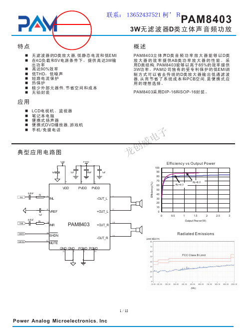
PAM8403中文规格书
n LCD
、
n
n
n
DVD
,
n
/
VDD
PVDD
1uF
1uF
470uF
1uF
13 4 6
0.47uF
Ri
INL
7
INL
VDD
PVDD PVDD
1
-OUT_L
8
VREF
1uF
0.47uF Ri INR
10
INR
3
+OUT_L
PAM8403
14
+OUT_R
SHDN MUTE
12
SHDN
5
MUTE
16
-OUT_R
,
1.0μF,
VDD
.
,
20μF(
)
.
(Ci)
,
.
.
, 100Hz 150Hz
(Ri)
fC= 1 2πRiCi
,
Ci
.
,
,
.,
.
(Ci)
,
,
(1/2 V ) DD . .
(C ) BYP
(CB ) YP .
.
, THD+N .
, CBYP
. PAM8403 PSRR
0.47μF 1.0μF
(C ) BYP
THD
.
/
.
/
V . DD .
.
VREF VREF
:PAM8403 ,
VREF .
,
. , 1/2
:
/
,
2
: VTH
1.3V@V = DD 5V,
/
, R1
MR16-6W新产品介绍
光电参数 部品介绍 光学原理 散热原理 电源方案 安装与修护 总 结
光电参数
Model
voltage AC6-12V 50/60HZ
Power
Light effect
PF
Protectio n grade IP20
Dimming
Lifespan
Dimension
MR16-6W
6W
75LM/W
1.光效方面:同种雾度的情况下,PMMA和PS的透光率能调的较PC高。 2.物理性能:相比之下,PS扩散板易碎,其次是PMMA扩散板,抗冲击性能最好的 数PC扩散板。
3.老化性能:PS扩散板最容易老化,PMMA其次,抗老化性能最好的是PC扩散板。
4.化学性能:PS扩散板较容易燃烧,PMMA其次,且PC扩散板具有良好的阻燃性能。
超薄设计结构:整体厚度小于15mm,采用飞利浦旗下NXP方案,可靠性高,性能 稳定,关键电子元件均采用国际一线品牌。 输入电压:AC6-12V 50Hz/不调光 AC15-20V 50/60Hz 功率:6W±5% 高功率因数:PF>0.7 高效率:满载功率时效率大于75% 低谐波:THD小于20% 满足EMI、EMC设计要求,以及SAA,CE等相关认证要求。 *调光:可控硅调光,兼容性强满足多数澳洲欧洲调光要求。 快速连接设计方式。
安装与维护
安装方便,内置驱动电源,接市电即可工作,电源可更换,维护方便
产品特点及卖点
节能省电
散热好 高寿命 高光效
安装方便
0.75
NO
40000h
¢50*48mm
长寿命,烟囱式散热,高亮度,光均匀
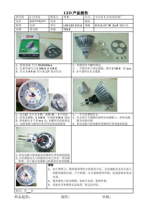
XX光电 MR16 3W(RMB7)的LED射灯拆解报告
LED 产品报告
供应商
X 洋光电 联系人 周’R 公司 中山市X 洋光电灯饰厂 电话
0137***51*** 传真 地址 种类
灯杯 型号 LSR-LED MR16 规格
MR16 12V 3W(3x1W)暖白光 品牌 莱司朗 价格 7RMB
1、彩盒包装 尺寸50x50x65mm
2、灯杯外观尺寸D:50MM H:54MM
3、灯头为MR16 用于接12V 低压灯头 1、外面用3个螺丝固定 2、一个铁环用于固定透镜,铁环D45MM 厚1mm 3、3个透明压光力透镜
1、内LED 芯片共3颗,每颗1W ,3个均布
2、铝基电路板,D:32MM 中间留D8MM 线孔
3、铝基板有3个D4mm 孔,3螺丝从此处固定
4、电路基板与散热灯杯用导电膏涂装接角 1、一个白色塑胶灯头
2、灯头的2个插脚直接焊在电路板上,供电电路
版为双面印刷
3、供电电路与铝基板间用锡焊红黑电线相连接
1、供电电路与铝基板间用锡焊红黑电线相连接
2、白色塑胶灯头与铝散热灯杯之间有一黑色橡
胶垫,用于隔开电路板与铝散热灯杯的接触
评估
1、 如左图所示,散热器周围有小的条形开孔,会造城蚊虫及灰尘进入
到散热器的内部,产生积累,长久影响使用环境,造成影响寿命及
光效。
2、 散热器加工较为粗糙,表面不光滑,影响外观。
3、 其他光学参数暂无法取得,暂无法评估。
附页,共 页
样品提供: 制作: 审核:。
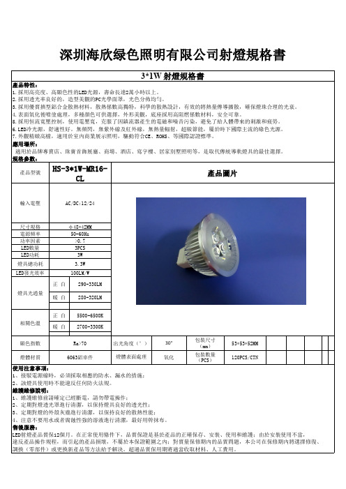
3W大功率MR16射灯规格书
違反產品操作規程,而引起的產品損壞,不屬於本保證範圍之內;對質量保修期內的品質問題,本公司在保修期內將選擇修復、
調換(零部件)或更換新產品等方法給予解決。超過品質保用期將適當收取材料、人工費用。
相關色溫
正白 暖白
5500-6500K 2700-3300K
顯色指數
Ra>70
出光角度(°)
30°
包裝尺寸 (mm)
53*53*52MM
燈體材質
6063鋁車件
燈體表面處理
氧化
包裝數量 (PCS)
120PCS/CTN
使用注意事項:
1、接駁電源線時,必須採取相應的防水、漏水的措施;
2、該燈具使用時不能違反任何防火法規。
規格參數:
HS-3*1W-MR16-
產品型號
CL
產品圖片
輸入電壓
AC/DC:12/24
尺寸規格 電源頻率 功率因素 LED數量 LED功耗 燈具總功耗 LED發光效率
燈具光通量
ф48*42MM 50-60Hz >0.7 3PCS 3W 3.3W 100LM/W
正 白 290-330LM
暖 白 280-320LM
維護維修說明:
1、維護維修前請確定已經斷電,請勿帶電操作;
2、定期對燈透光罩進行清潔,以保持燈具良好的透光性;
3、定期對燈的外殼灰塵進行清潔,以保持良好的散熱性能;
4、注意不要用水或者腐蝕性強的溶液進行清潔,最好用幹抹布。
售後服務:
LED射燈產品質保2個月。在正常使用條件下,品質保證是基於產品的正確保存、安裝、使用和維護;由於安裝使用不當,
深圳海欣绿色照明有限公司射燈規格書
3*1W 射燈規格書
產品特性:
高亮度SMT圆形红、黄、绿和蓝色LED灯(型号 ALMD-EL3E, ALMD-EG3E, ALM

ALMD-EL3E, ALMD-EG3E, ALMD-CM3E, ALMD-CB3EHigh Brightness SMT RoundRed, Amber, Green and Blue LED LampsData SheetFeatures• Compact form factor • High brightness material• Available in Red, Amber, Green and Blue color • Red AlInGaP 626 nm • Amber AlInGaP 590 nm • Green InGaN 525 nm • Blue InGaN 470 nm • JEDEC MSL 2A• Compatible with reflow soldering process • Tinted lens• Typical viewing angle: 30°Applications• Full color signs • Mono color signsNotes:1. All dimensions in millimeters (inches).2. Tolerance is ± 0.20 mm, unless otherwise specified.3. Mildsteel leadframe.DescriptionThe new Avago ALMD-xx3E LED series has the same or just slightly less luminous intensity than conventional high brightness, through-hole LEDs.The new LED lamps can be assembled using common SMT assembly processes and are compatible with indus-trial reflow soldering processes.The LEDs are made with an advanced optical grade epoxy for superior performance in outdoor sign applications. For easy pick and place assembly, the LEDs are shipped in tape and reel. Every reel is shipped from a single intensity and color bin– except the red color–for better uniformity.Package DimensionsCAUTION: InGaN devices are Class 1C HBM ESD sensitive, AlInGaP devices are Class 1B ESD sensitive per JEDEC Standard.Please observe appropriate precautions during handling and processing. Refer to Application Note AN-1142 for additional details.CAUTION: Customer is advised to always keep the LED in the MBB with <5% RH when not in use as prolonged exposure to environment might cause the silver-plated leads to tarnish or rust, which might cause difficulties in soldering.1.4Package MarkingA: Anode C: CathodeDevice Selection GuidePart Number Color and Dominant Wavelengthλd (nm) Typ. [3]Luminous Intensity Iv (mcd) [1,2,5]Viewing AngleTyp. (°) [4] Min.Max.ALMD-EG3E-VX002Red 6264200930030°ALMD-EL3E-VX002Amber 59042009300ALMD-CM3E-Y1002Green 525930021000ALMD-CB3E-SU002Blue 47019004200Notes:1. The luminous intensity is measured on the mechanical axis of the lamp package and it is tested with pulsing condition.2. The optical axis is closely aligned with the package mechanical axis.3. Dominant wavelength, λd, is derived from the CIE Chromaticity Diagram and represents the color of the lamp.4. θ½ is the off-axis angle where the luminous intensity is half the on-axis intensity.5. Tolerance for each bin limit is ± 15%.Part Numbering SystemA L M D-x1x2x3x4-x5x6x7x8x9Code Description Optionx1Package type EC Round AlInGaP Round InGaNx2Color BGLM Blue Red Amber Greenx3Viewing angle330°x4Product specific designation Ex5Minimum intensity bin Refer to device selection guidex6Maximum intensity bin Refer to device selection guidex7Color bin selection0Full distributionx8x9Packaging option 02Tested 20mA, 13inch carrier tapeAbsolute Maximum Rating, T J = 25 °CParameter Red and Amber Green Blue Unit DC Forward Current [1]503020mA Peak Forward Current100 [2]100 [3]100 [3]mA Power Dissipation12011476mW LED Junction Temperature110°C Operating Temperature Range-40 to +85°C Storage Temperature Range-40 to +100°C Notes:1. Derate linearly as shown in Figure 4 and Figure 9.2. Duty Factor 30%, frequency 1 kHz.3. Duty Factor 10%, frequency 1 kHz.Electrical / Optical Characteristics, T J = 25 °CParameter Symbol Min.Typ.Max.Units Test ConditionsForward Voltage RedAmberGreenBlue V F1.81.82.82.82.12.13.23.22.42.43.83.8V I F = 20 mAReverse Voltage [3] Red & Amber Green & Blue V R55V I R = 100 µAI R = 10 µADominant Wavelength [1] RedAmberGreenBlue λd618.0584.5519.0460.0626.0590.0525.0470.0630.0594.5539.0480.0I F = 20 mAPeak Wavelength RedAmberGreenBlue λPEAK634594516464nm Peak of Wavelength of SpectralDistribution at I F = 20 mAThermal Resistance RedAmberGreenBlue RθJ-PIN270270270480°C/W LED Junction-to-PinLuminous Efficacy [2] RedAmberGreenBlue ηV20049053065lm/W Emitted Luminous Power/EmittedRadiant PowerThermal coefficient of λd RedAmberGreenBlue 0.0590.1030.0280.024nm/°C I F = 20 mA ; +25 °C ≤ T J ≤ +100 °CNotes:1. The dominant wavelength is derived from the chromaticity diagram and represents the color of the lamp.2. The radiant intensity, I e in watts per steradian, may be found from the equation I e = I V/ηV where I V is the luminous intensity in candelas and ηV isthe luminous efficacy in lumens/watt.3. Indicates product final testing condition. Long-term reverse bias is not recommended.Figure 1. Relative Intensity vs. Wavelength Figure 2. Forward Current vs. Forward VoltageFigure 3. Relative Intensity vs. Forward Current Figure 4. Maximum Forward Current vs. Ambient TemperatureFigure 5. Relative Dominant Wavelength Shift vs. Forward Current0.00.20.40.60.81.0500550600650AmberRed010203040506000.51 1.52 2.530.00.51.01.52.02.53.001020304050600102030405060-0.8-0.6-0.4-0.200.20.40.60.811.20102030405060WAVELENGTH - nmR E L A T I V E I N T E N S I T YFORWARD VOLTAGE - VF O R W A R D C U R R E N T - m AT A - AMBIENT TEMPERATURE - °CM A X I M U M F O R W A R D C U R R E N T - m ARedAmberFORWARD CURRENT - mAR E L A T I V E L U M I N O U S I N T E N S I T Y (N O R M A L I Z E D A T 20 m A )RedAmberFORWARD CURRENT - mAR E L A T I V E D O M I N A N T W A V E L E N G T H S H I F T - n mFigure 6. Relative Intensity vs. WavelengthFigure 7. Forward Current vs. Forward VoltageFigure 8. Relative Intensity vs. Forward Current Figure 9. Maximum Forward Current vs. Ambient TemperatureFigure 10. Dominant Wavelength Shift vs. Forward Current010*********406080100-10-50510020406080100GreenBlueFORWARD CURRENT - mAR E L A T I V E D O M I N A N T W A V E L E N G T H S H I F T (N O R M A L I Z E D A T 20 m A )T A - AMBIENT TEMPERATURE - °CM A X I M U M F O R W A R D C U R R E N T - m ABlueGreen0.00.10.20.30.40.50.60.70.80.91.0WAVELENGTH - nmR E L A T I V E I N T E N S I T YGREEN BLUE 05101520253001234FORWARD VOLTAGE - VF O R W A R D C U R R E N T - m A 0.00.20.40.60.81.01.21.451015202530DC FORWARD CURRENT - mAR E L A T I V E L U M I N O U S I N T E N S I T Y (N O R M A L I Z E D A T 20 m A )Figure 11a. Radiation Pattern for x-axis Figure 11b. Component Axis for Radiation PatternFigure 12. Relative Intensity Shift vs. Junction Temperature Figure 13. Forward Voltage Shift vs. Junction TemperatureFigure 14. Recommended Soldering Land PatternNote: Recommended stencil thickness is 0.1524mm (6 mils) minimum andabove00.20.40.60.81-90-60-300306090ANGULAR DISPLACEMENT-DEGREEN O R M A L I Z E D I N T E N S I T YN O R M A L Z I E D I N T E N S I T Y (P H O T O )TJ - JUNCTION TEMPERATURE (°C)F O R W A R D V O L T AG E SHI F T - VTJ - JUNCTION TEMPERATURE (°C)Figure 17. Unit Orientation from reel Figure 15. Carrier Tape DimensionIntensity Bin Limit Table (1.3:1 Iv bin ratio)Bin Intensity (mcd) at 20 mA Min.Max.S1******* T25003200 U32004200 V42005500 W55007200 X72009300 Y930012000 Z1200016000 11600021000 Tolerance for each bin limit is ± 15%V F Bin Table (V at 20 mA) for Red and Amber only Bin ID Min.Max. V D 1.8 2.0 V A 2.0 2.2 V B 2.2 2.4 Tolerance for each bin limit is ± 0.05 VRed Color RangeMin Dom Max Dom X min Y Min X max Y max 618.0630.00.68720.31260.68900.29430.66900.31490.70800.2920 Tolerance for each bin limit is ± 0.5nmAmber Color RangeBin MinDomMaxDom Xmin Ymin Xmax Ymax1584.5587.00.54200.45800.55300.44000.53700.45500.55700.4420 2587.0589.50.55700.44200.56700.42500.55300.44000.57200.4270 4589.5592.00.57200.42700.58200.41100.56700.42500.58700.4130 6592.0594.50.58700.41300.59500.39800.58200.41100.60000.3990 Tolerance for each bin limit is ± 0.5nm Green Color RangeBinMinDomMaxDom Xmin Ymin Xmax Ymax 1519.0523.00.06670.83230.14500.73190.12000.73750.09790.8316 2523.0527.00.09790.83160.17110.72180.14500.73190.13050.8189 3527.0531.00.13050.81890.19670.70770.17110.72180.16250.8012 4531.0535.00.16250.80120.22100.69200.19670.70770.19290.7816 5535.0539.00.19290.78160.24450.67470.22100.69200.22330.7600 Tolerance for each bin limit is ± 0.5nmBlue Color RangeBinMinDomMaxDom Xmin Ymin Xmax Ymax 1460.0464.00.14400.02970.17660.09660.18180.09040.13740.0374 2464.0468.00.13740.03740.16990.10620.17660.09660.12910.0495 3468.0472.00.12910.04950.16160.12090.16990.10620.11870.0671 4472.0476.00.11870.06710.15170.14230.16160.12090.10630.0945 5476.0480.00.10630.09450.13970.17280.15170.14230.09130.1327 Tolerance for each bin limit is ± 0.5nmNote: Acronyms and Definition:BIN:(i) Color bin only or V F bin only(Applicable for part number with color bins but with-out V F bin or part number with V F bins and no color bin) (ii) Color bin incorporated with V F binApplicable for part number that have both color bin and V F bin Example:a. Color bin only or V F bin only BIN: 4 (represent color bin 4 only) BIN: V A (represent V F bin “V A” only)b. Color bin incorporate with V F binBIN: 4 VAVA: VF bin “VA”4: Color bin 4 onlyPacking Label(i) Mother Label (Available on MBB bag) (ii) Baby Label (Available on Plastic Reel)SolderingRecommended reflow soldering condition:a. Reflow soldering must not be done more than twotimes. Do observe necessary precautions for handling a moisture-sensitive device, as stated in the following section.b. Recommended board reflow direction:(i) Leaded reflow soldering:(ii) Lead-free reflow soldering:c. Do not apply any pressure or force on the LED during reflow and after reflow when the LED is still hot.d. It is preferred that you use reflow soldering to solder the LED. Use hand soldering only for rework if unavoidable but must be strictly controlled to the following conditions:- Soldering iron tip temperature = 320 °C max.- Soldering duration = 3 sec max.- Number of cycles = 1 only- Power of soldering iron = 50 W max.e. Do not touch the LED body with a hot soldering iron except the soldering terminals as this may damage the LED.f. For de-soldering, it is recommended to use appropriate double head soldering iron. User is advised to confirm beforehand whether the functionality and performance of the LED is affected by hand soldering.TIMETIMET E M P E R A T U RE11PRECAUTIONARY NOTES1. Handling precautionsFor automated pick and place, Avago has tested nozzle size below made with urethane material to be working fine with this LED. However, due to the possibility of variations in other parameters such as pick and place machine maker/model and other settings of the ma-chine, customer is recommended to verify the nozzle selected.d. Control of assembled boards- If the PCB soldered with the LEDs is to be subjected to other high temperature processes, the PCB need to be stored in sealed MBB with desiccant or desiccator at <5%RH to ensure that all LEDs have not exceeded their floor life of 672 hours.e. Baking is required if:- The HIC indicator is not BROWN at 10% and is AZURE at 5%.- The LEDs are exposed to condition of >30°C / 60% RH at any time.- The LED floor life exceeded 672hrs.The recommended baking condition is: 60±5ºC for 20hrs. Baking should only be done once. f. Storage- The soldering terminals of these Avago LEDs are silver plated. If the LEDs are being exposed in ambient environment for too long, the silver plating might be oxidized and thus affecting its solderability performance. As such, unused LEDs must be kept in sealed MBB with desiccant or in desiccator at <5%RH.3. Application precautionsa. Drive current of the LED must not exceed the maximum allowable limit across temperature as stated in the datasheet. Constant current driving is recommended to ensure consistent performance.b. LED is not intended for reverse bias. Do use other appropriate components for such purpose. When driving the LED in matrix form, it is crucial to ensure that the reverse bias voltage is not exceeding the allowable limit of the LED.c. Avoid rapid change in ambient temperature especially in high humidity environment as this will cause condensation on the LED.d. If the LED is intended to be used in outdoor or harsh environment, the LED leads must be protected with suitable potting material against damages caused by rain water, oil, corrosive gases etc. It is recommended to have louver or shade to reduce direct sunlight on the LEDs.4. Eye safety precautionsLEDs may pose optical hazards when in operation. It is not advisable to view directly at operating LEDs as it may be harmful to the eyes. For safety reasons, use ap-propriate shielding or personal protective equipments.Note:1. Nozzle tip should touch the LED flange during pick and place.2. Outer dimensions of the nozzle should be able to fit into the carrier tape pocket.2. Handling of moisture-sensitive deviceThis product has a Moisture Sensitive Level 2a rating per JEDEC J-STD-020. Refer to Avago Application Note AN5305, Handling of Moisture Sensitive Surface Mount Devices, for additional details and a review of proper handling procedures.a. Before use- An unopened moisture barrier bag (MBB) can be stored at <40°C/90%RH for 12 months. If the actual shelf life has exceeded 12 months and the humidity Indicator Card (HIC) indicates that baking is not required, then it is safe to reflow the LEDs per the original MSL rating.- It is recommended that the MBB not be opened prior to assembly (e.g. for IQC). b. Control after opening the MBB- The humidity indicator card (HIC) shall be read immediately upon opening of MBB.- The LEDs must be kept at <30°C / 60%RH at all times and all high temperature related processes including soldering, curing or rework need to be completed within 672 hours.c. Control for unfinished reel- Unused LEDs must be stored in a sealed MBB with desiccant or desiccator at <5%RH.>3.5mmFor product information and a complete list of distributors, please go to our web site: Avago, Avago Technologies, and the A logo are trademarks of Avago Technologies in the United States and other countries.Data subject to change. Copyright © 2005-2015 Avago Technologies. All rights reserved. AV02-4540EN - April 27, 2015DISCLAIMER: Avago’s products and sof tware are not specifically designed, manuf actured or authorized f or sale as parts, components or assemblies for the planning, construction, maintenenace or direct operation of a nuclear facility or for use in medical devices or applications. Customer is solely responsible, and waives all rights to make claims against avago or its suppliers, for all loss, damage, expense or liability in connection with such use.。
照明灯具产品参数手册
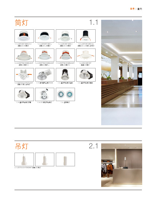
LXPT MC20 HE WT 830 L90 LXPT MC20 HE WT 840 L90 LXPT MC20 HE WT 765 L90 LXPT MC20 ECO WT 830 L90 LXPT MC20 ECO WT 840 L90 LXPT MC20 ECO WT 765 L90 LXPT MC12 ECO WT 830 L90 LXPT MC12 ECO WT 840 L90 LXPT MC12 ECO WT 765 L90
10.2 GLAXIER凌星T5吸顶灯 C104 鸟巢型
10.2 GLAXIER凌星T5吸顶灯 C10 G2畅明LED路灯
11.2 绚亮LED路灯
11.1
目录 | 室外
泛光灯
12.1
12.1 PURSOS LED FLOOD 绚丽LED泛光灯
12.2 PURSOS® High Power LED Flood Light
绚丽LED筒灯 8'
绚丽LED筒灯 6'
绚丽LED筒灯 4'
1.8 LEDCOMFORT 皓睿LED筒灯
1.9 LEDTOUCH SPOTLIGHT 绚亮LED嵌入式射灯
1.11 插拔管专业筒灯 DDE
1.12 星月节能筒灯竖插
1.13 星月节能筒灯横插
1.14 星月节能筒灯防雾
1.15 CFL高效节能筒灯
极坐标光强分布 LXPT MC20 ECO 4000K
极坐标光强分布 LXPT MC20 ECO 6500K
1.1
筒灯 | 绚亮LED筒灯 极坐标光强分布 LXPT MC12 ECO 3000K
极坐标光强分布 LXPT MC12 ECO 4000K
极坐标光强分布 LXPT MC12 ECO 6500K
MAX1978中文数据手册

用于Peltier模块的集成温度控制器概论MAX1978 / MAX1979是用于Peltier热电冷却器(TEC)模块的最小, 最安全, 最精确完整的单芯片温度控制器。
片上功率FET和热控制环路电路可最大限度地减少外部元件, 同时保持高效率。
可选择的500kHz / 1MHz开关频率和独特的纹波消除方案可优化元件尺寸和效率, 同时降低噪声。
内部MOSFET的开关速度经过优化, 可降低噪声和EMI。
超低漂移斩波放大器可保持±0.001°C的温度稳定性。
直接控制输出电流而不是电压, 以消除电流浪涌。
独立的加热和冷却电流和电压限制提供最高水平的TEC保护。
MAX1978采用单电源供电, 通过在两个同步降压调节器的输出之间偏置TEC, 提供双极性±3A输出。
真正的双极性操作控制温度, 在低负载电流下没有“死区”或其他非线性。
当设定点非常接近自然操作点时, 控制系统不会捕获, 其中仅需要少量的加热或冷却。
模拟控制信号精确设置TEC 电流。
MAX1979提供高达6A的单极性输出。
提供斩波稳定的仪表放大器和高精度积分放大器, 以创建比例积分(PI)或比例积分微分(PID)控制器。
仪表放大器可以连接外部NTC或PTC热敏电阻, 热电偶或半导体温度传感器。
提供模拟输出以监控TEC温度和电流。
此外, 单独的过热和欠温输出表明当TEC温度超出范围时。
片上电压基准为热敏电阻桥提供偏置。
MAX1978 / MAX1979采用薄型48引脚薄型QFN-EP 封装, 工作在-40°C至+ 85°C温度范围。
采用外露金属焊盘的耐热增强型QFN-EP封装可最大限度地降低工作结温。
评估套件可用于加速设计。
应用光纤激光模块典型工作电路出现在数据手册的最后。
WDM, DWDM激光二极管温度控制光纤网络设备EDFA光放大器电信光纤接口ATE特征♦尺寸最小, 最安全, 最精确完整的单芯片控制器♦片上功率MOSFET-无外部FET♦电路占用面积<0.93in2♦回路高度<3mm♦温度稳定性为0.001°C♦集成精密积分器和斩波稳定运算放大器♦精确, 独立的加热和冷却电流限制♦通过直接控制TEC电流消除浪涌♦可调节差分TEC电压限制♦低纹波和低噪声设计♦TEC电流监视器♦温度监控器♦过温和欠温警报♦双极性±3A输出电流(MAX1978)♦单极性+ 6A输出电流(MAX1979)订购信息* EP =裸焊盘。
3W射灯参数表
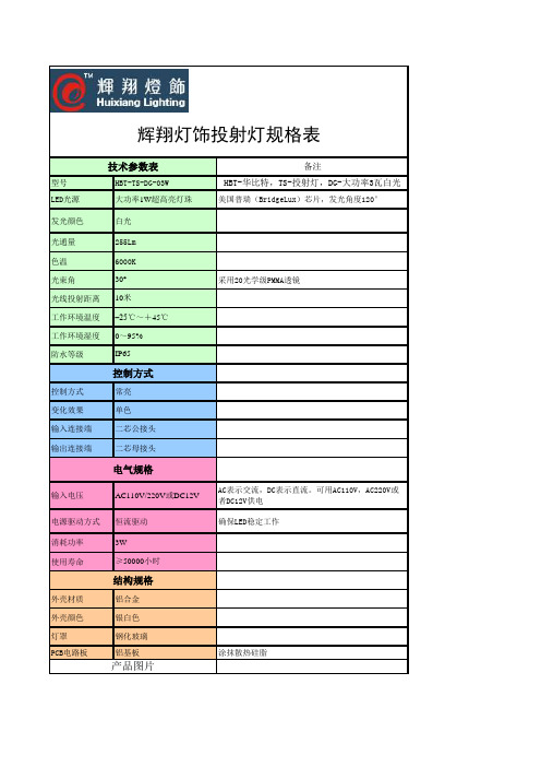
型号 LED光源
技术参数表
HBT-TS-DG-03W 大功率1W超高亮灯珠
发光颜色
白光
光通量
255Lm
色温
6000K
光束角
30°
光线投射距离 ቤተ መጻሕፍቲ ባይዱ0米
工作环境温度 –25℃~+45℃
工作环境湿度 0~95%
防水等级
IP65
控制方式
控制方式
常亮
变化效果
单色
输入连接端
二芯公接头
输出连接端
二芯母接头
电气规格
输入电压
AC110V/220V或DC12V
电源驱动方式 恒流驱动
消耗功率 使用寿命
外壳材质 外壳颜色 灯罩 PCB电路板
3W ≥50000小时
结构规格
铝合金 银白色 钢化玻璃 铝基板
产品图片
备注 HBT-华比特,TS-投射灯,DG-大功率3瓦白光 美国普瑞(BridgeLux)芯片,发光角度120° 采用20光学级PMMA透镜
AC表示交流,DC表示直流。可用AC110V,AC220V或 者DC12V供电 确保LED稳定工作
涂抹散热硅脂
LED MR16灯头的详细讲解

MR16(有時稱為MR-16)是一種由眾多製造商所製定的標準規格鹵素反射燈。
現今MR16型式的LED燈也可見到。
MR16燈經常用來代替緊湊型熒光燈或標準白熾燈泡的應用,包括住宅照明和零售照明。
MR16燈最初是被設計用於幻燈機。
他們適合於各種的應用場合,需要從低到中等強度的指向性照明,例如追蹤照明、凹天花板燈、枱燈、吊燈、燈具、景觀照明、零售展示照明和自行車頭燈。
命名由來MR16是一種命名編號,其中「MR」是代表多重反射罩(Multifaceted Reflector)。
16是代表前直徑的長度,為多少單位長的倍數,規定8個單位長為1英吋。
以MR16為例,前直徑是16個單位長,則前直徑是2英吋,即2x2.54cm =5.04cm,口徑約長5公分。
MR16 and MR11 (sometimes referred to as MR-16 or MR-11, rarely MR8 or MR-8) are standard formats for halogen multifaceted reflector light bulbs made by a variety of manufacturers. MR16-compatible LED lamps are also available. MR16 lamps are regularly used in place of standard incandescent light bulbs for applications including residential lighting and retail lighting, while MR11 ones are used in specialty applications. MR16 lamps were originally designed for use in slide projectors. They are well suited to a variety of applications that require directional lighting of low to medium intensity, such as track lighting, recessed ceiling lights(only if not dichroic[citation needed]), desk lamps, pendant fixtures, landscape lighting, retail display lighting and bicycle headlights[citation needed].DesignationMR16 is a coded designation in which MR stands for multifaceted reflector, and 16 is the number of eighths of an inch the front is in diameter. An MR16 is 2 inches (51 mm), an MR11 is 1.375 inches (35 mm).Halogen MR16 characteristicsDesign and constructionHalogen MR16 lamps consist of a halogen capsule (bulb) integrated with a pressed glass reflector. The reflector of an MR16 lamp is 2 inches (50mm) in diameter. The base conforms to bi-pin GU5.3 standard. The compact size of the MR16 allows for much smaller, more discreet fixtures than the incandescent reflector bulbs that pre-dated MR16s.The reflector controls the direction and spread of light cast from the lamp. MR16 lamps are available with different beam angles from narrow spot lights of as small as 7 degrees to wide flood lamps of 60 degrees."MR" refers to multifaceted reflector, indicating that this reflector is usually shaped with multiple small facets. This multifaceted reflector gives a soft edge to the area illuminated by the lamp. MR16 lamps are also available with smooth reflectors, resulting in a sharper fall-off to the illuminated area. "16" refers to the maximum diameter of the lamp in eighths of an inch, 16/8" or 2 inches (5 cm).Dichroic reflectorsIn less-expensive lamps, the reflector has an aluminium coating that reflects all light. In more-expensive lamps, the reflector commonly has a dichroic coating that reflects particular frequencies of the visible spectrum in the direction the lamp is facing, while not reflecting infrared light. By not reflecting infrared light (which produces heat), these lamps reduce the amount of heating of the subject upon which they are focused. The combination of the halogen light source and dichroic coating also means that these lamps provide a high color rendering index and a higher color temperature than standard incandescent bulbs. This makes them well suited to applications where color rendering is important, such as retail display lighting.IEC 60598 No Cool Beam symbolDichroic lamps, however must never be used in recessed lighting as they are a common ignitionsource for building fires.[citation needed] In some countries (e.g. UK, Australia), lamps suitable for use in recessed lighting can be identified by the IEC 60598 No Cool Beam symbol. OperationThe brightness of MR16 lamps can be adjusted when used with appropriate light fixtures and dimmers. However, the color temperature changes significantly when the lamp is dimmed.MR16 lamps produce significant heat, and care must be taken to avoid contact with skin or proximity to flammable materials when the lamp is on or has been on recently.Halogen MR16 lamps are typically more efficient than standard incandescent bulbs, but not nearly as efficient as fluorescent lamps or LED technology. MR16 lamps typically have a life expectancy of 1000 to 3000 hours.With both types of incandescent bulbs, useful life can be considerably shortened if their filaments experience mechanical shock or vibration. Using an electronic transformer with a 'soft start' feature can considerably extend life as it reduces the characteristically high inrush current which occurs shortly after switch-on. Additionally, it can be less strainful on the eyes, giving the pupils more time to react to a sudden increase in environmental lighting level.MR16 lamps, like all quartz-halogen lamps, produce substantial amounts of ultraviolet light. Usually, this must be filtered out. Also, the quartz capsule of the lamp sometimes ruptures ("explodes") upon failure of the lamp. For these two reasons, some MR16 lamps include a cover glass that serves as an integrated ultraviolet filter and explosion shield. MR16 lamps lacking this cover require the use of a fixture that incorporates an external piece of glass specifically designed to provide this protection.Compatible LED replacementsMain article: LED bulbLED MR11, 70 lm/W LED MR16MR16-compatible LED lamps are also available. They are similar in shape to halogen MR16 lamps, and can be used in most fixtures designed for MR16 lamps. The same is true of MR11-compatible LED lamps.Versions of the led lamps have been patented in the UK[citation needed]. Due to the low heat and power consumption, they have been produced from plastic, although this does not affect their efficiency. Their non-polarised AC/DC operation, with current limitation over a wide voltage range (11.5 ~ 18 volts as a standard 12 volt version), allows a wide range of usage.Average rated life, as quoted by manufacturers, is typically 30,000–50,000 hours depending on theproduct in question. This amounts to continuous operation for 1250–2080 days or approximately 24 hours per day, for three to six years.Fixtures designed for halogen MR16 or MR11 lamps that use electronic transformers may need to be retrofitted with LED-compatible transformers. This is because the standard electronic transformers have a minimum power-usage requirement in order to function. Some LED-lamps may be below this usage requirement. Fixtures that use magnetic transformers can generally be used with LED-lamps without modification.LED-lamps from some manufacturers incorporate full wave rectification circuitry into the 'bulb', so that either AC or DC can be used, whilst others require a DC supply and correct polarity.At this time, there are few standards for MR16 and MR11 compatible LED lamps. As such there is a wide variety of designs, varying significantly with regard to beam width, light colour, efficiency and luminous power.Unlike halogen MR16s, LED-lamps often do not have the multifaceted reflectors that give MR16s their precise beam width control. Some rely on the optics of the LED(s) to control the beam width. Some designs may have simple cut-off apertures that limit beam width, or even individual reflectors for each LED.As with other LED lamps available today, the quality and color temperature of the white light produced by such lamps varies. Many tend towards the blue end of the spectrum, being even "cooler"-coloured than fluorescent lighting. Because of this variability, some MR16 and MR11 compatible LED lamps will create significantly more natural looking light than others.The least efficient of these lamps produce about 26 lumens per watt (lm/W), which is similar to the efficiency of halogen MR16s. The most efficient of these lamps available today produce about 100 lm/W, which exceeds the efficiency of compact fluorescent lamps.In terms of total luminous power, such lamps range from being significantly less powerful than their halogen counterparts, to being comparable to the lower power halogen MR16s. The brightest available halogen MR16s are still slightly brighter than the brightest available LED versions.VariationsMR16 lamps most often operate at 12 volts, although they are also available in other voltages. The common 12-volt MR16 lamps therefore require a magnetic or electronic transformer (sometimes misnamed as a ballast) to convert the 120 or 240 volt mains voltage to the very low operating voltage required by the lamp. Note that although halogen MR16 lamps can usually operate on either AC or DC voltage, LED devices require DC voltage and as such will require a rectifier in the unit if AC is to be used.Certain MR16 lamps can operate directly on the mains voltage. These lamps typically use a GU10 turn-and-lock base, so they cannot be accidentally interchanged with low-voltage lamps. As such, they are often referred to as GU10 rather than MR16 lamps. Because of their use of much-finer wire, the filaments of lamps that operate directly from mains voltage are much more fragile than those used in low-voltage lamps.Low-voltage MR16 lamps almost always have ANSI standard GU5.3 two-pin bases. MR16 lamps with an integrated transformer are also available. These lamps have screw bases to fit standard medium-base Edison sockets.Smaller lamps are also manufactured in the less common MR11 and even less common MR8formats, which have reflectors that are 1⅜ inch (11/8" or 35 mm) and 1 inch (8/8" or 25 mm) in diameter, respectively. These smaller lamps appear very similar to MR16 lamps, also featuring similar multifaceted reflectors that are available in a variety of beam spreads. Their smaller size makes possible even smaller fixtures, but limits them to lower powers. MR11 and MR8 lamps have pins placed more closely together, preventing them from accidentally being interchanged with MR16 lamps.Feit Electric produces a compact fluorescent version that can replace an MR16, however this runs only a few watts, and scatters the small amount of light widely, thus is only suitable for limited applications.ANSI designationsA typical MR16 lampThe following ANSI standard codes are used to designate certain power and beam angle combinations for MR16 lamps. Many manufacturers use these standard codes for lamps matching these specifications:ESX: 20 watt, 10 degree beam (20MR16/10°)BAB: 20 watt, 35 degree beam (20MR16/35°)EXT: 50 watt, 15 degree beam (50MR16/15°)EXZ: 50 watt, 25 degree beam (50MR16/25°)EXN: 50 watt, 40 degree beam (50MR16/40°)FNV: 50 watt, 60 degree beam (50MR16/60°)FPA: 65 watt, 15 degree beam (65MR16/15°)FPC: 65 watt, 25 degree beam (65MR16/25°)FPB: 65 watt, 40 degree beam (65MR16/40°)EYF: 75 watt, 15 degree beam (75MR16/15°)EYJ: 75 watt, 25 degree beam (75MR16/25°)EYC: 75 watt, 40 degree beam (75MR16/40°)Note that MR16 lamps are available in many other power and beam combinations than those available above. For this reason, MR16 lamps are also often labeled according to beam spread abbreviations. Note that these while these abbreviations are commonly used, the angles associated with these abbreviations vary slightly from manufacturer to manufacturer. These are typical beam angles for these beam spread abbreviationsVNSP (very narrow spot): less than 8 degrees NSP (narrow spot): 8-15 degreesSP (spot): 8-20 degreesNFL (narrow flood): 24-30 degreesFL (flood): 35-40 degreesWFL (wide flood): 55-60 degreesVWFL (very wide flood): 60 degrees or more。
OMRON F3SJ安全光栅(Type4) 说明书
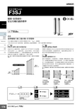
安全光柵(Type4) F3SJ174安全光柵(Type4)F3SJ簡單、容易使用。
安全光柵的最新標準特長選擇機種只要三個步驟,非常簡單。
安全光柵F3SJ型屬於安全對策分類類別 4中的「Type 4」感測器。
可省去您在安全性方面的煩惱,選擇裝置之最適用機種時,只要三個步驟即可簡單進行。
OMRON安全光柵的特點,也就是“JUST FIT ”的思考方式也被應用在F3SJ型中。
以一光軸為單位,產品系列齊全,具有可適用於各種裝置的感測器尺寸。
含蓋防護範圍所需之最小限度的感測器長度可從第178~179頁的型式一覽表中選擇。
(註:型式一覽表中所未記載的長度之感測器亦可另行製作,請向本公司業務部洽詢。
)架構符合機械指令的安全系統或是與專用的控制器(F3SP-B1P 型或F3SX型)搭配時,請選擇PNP型。
另備有標準品NPN型,可做為先前的區域感測器的替代品之用。
備有手指檢視用、手部檢測用、手/腕/腳/人體檢測用的三種系列。
在距離危險處較近的場所內使用時,可以選擇手指檢測模型。
若在距離危險處有一定的距離且機械停止動作前的時間尚稱充裕的場所中使用時,則可以選擇最經濟的手腕檢測型。
可因應顧客的使用需求來選擇機型。
(註:選擇機型後,請計算第217頁中所記載的安全距離,並視需求來再次選定機種。
)請參閱第215頁的「安全注意事項」。
σ ɶЙ Ң ωǾIJĵŮŮĩӎ ĺŮŮĪЙ Ң ωǾijıŮŮĩӎ IJĶŮŮĪЙ ʂΡ Ң ωǾĴıŮŮĩӎ ijĶŮŮĪ薄型、易於使用、簡單安裝的光柵感測器本體達到薄型化。
與本公司先前的產品相較之下,厚度只有6mm。
包含配合光軸的新型安裝金具後的厚度只有26mm,與舊型產品相較之下,厚度從45mm減小19mm。
在追加為現行機械之安全對策時,完全不會造成妨礙。
採用彎度為R5的柔軟纜線,配線輕鬆容易。
配線採用附有M12 接頭的纜線(0.3 m),可隨意拉出,不會因連接頭機種而有型式上的差異。
附標準配件金具,容易使用。
ND16系列信号灯
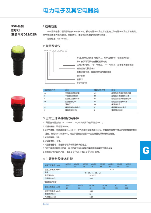
白、绿、
ND16-22C/2 AC/DC220V
ND16-22C/2 AC/DC6V
红、黄、
ND16-22C/2 AC/DC380V
ND16-22C/2 AC/DC12V
蓝
ND16-22C/4 AC/DC220VF
ND16-22C/2 AC/DC24V
ND16-22C/4 AC/DC380VF
ND16-22C/2 AC/DC36V
3 正常工作条件和安装条件
3.1 周围空气温度为:-5℃~+40℃,24小时内其平均值不超过+35℃。
3.2 海拔高度:不超过2000m。
3.3 大气条件:在最高温度为+40℃时,空气的相对湿度不超过50%,在较低的温度下可以允许有较高的相对
湿度,例如+20℃时达90%。对由于温度变化偶尔产生的凝露应采取特殊的措施。
母结构,使产品在安装板孔径Φ22.5、Φ25.5的情况下通用。 5.2 使用说明 5.2.1 安装步骤: a.信号灯在安装使用前应先检查一下额定工作电压是否符合使用要求; b.使用前,先拆下信号灯上的塑料锁定螺母,把信号灯从面板前方装入,再从面板后拧紧塑料锁定螺母
使信号灯紧固在面板上,最后把电源 线接上。
62 12
64 15
Φ30.5 Φ30
ND16-22D/4 AC110V ND16-22D/4 AC220V ND16-22D/4 AC380V ND16-22D/2 AC/DC6V ND16-22D/2 AC/DC12V ND16-22D/2 AC/DC24V ND16-22D/2 AC/DC36V
AC/DC 110
≤20
AC/DC 220
AC/DC 380
AC/DC 24
射灯Mr射灯节能改造方案赛德利
LED射灯、Mr16射灯节能改造方案-赛德利
商业店铺、酒店、展厅、办公及居家等关键照明使用卤素灯杯情况下用LED Mr16 射灯进行节能改造替换, 我们来看一下LED Mr16 射灯系列表现吧:
赛德利LED Mr16 射灯
特征
◆显色性好, 有利于提升大家反应速度和识别能力;
◆冷光源, 无热辐射, 无有害金属汞, 绿色环境保护;
◆使用寿命强, 维护成本极低;
◆灯体采取全铝散热, 抗冲擎性好, 面罩采取PMMA材料。
高透光率, 光速集中效果好;
◆可直接替换传统卤素灯光源, 节能效果80%以上;
◆无闪烁现象, 对人眼没有伤害, 此款MR16射灯能兼容国际品牌: 飞利浦、欧司朗等变压器, 中国品牌能兼容: 雷士、品上、欧普、三雄极光等电子变压器。
兼容性90%以上, 效果极佳。
适用范围
商业店铺、酒店、展厅、办公及居家等关键照明
节能计算
◆ 3w替换20w卤素灯杯, 节能率80%;
◆ 5w替换35w卤素灯杯, 节能率86%;。
- 1、下载文档前请自行甄别文档内容的完整性,平台不提供额外的编辑、内容补充、找答案等附加服务。
- 2、"仅部分预览"的文档,不可在线预览部分如存在完整性等问题,可反馈申请退款(可完整预览的文档不适用该条件!)。
- 3、如文档侵犯您的权益,请联系客服反馈,我们会尽快为您处理(人工客服工作时间:9:00-18:30)。
龙茂微电子开发成功
3×3W大功率MR16射灯
无论在商场或家庭中都广泛采用射灯,以用来照明特定的目标。
原来这种射灯是采用卤素灯,而且它采用了一种已经成为标准的mr16插座。
由于卤素灯的发光效率和白炽灯一样是很低的,寿命也只有2000小时左右,所以理当成为led所取代的对象。
在目前市场上最为流行的mr16型led射灯是3×1w的。
采用mr16的目的是为了便于取代原来的卤素灯,只要拔下插入就可以了。
然而通常卤素灯的功率为50w,最大功率的石英卤素灯可以达到100 w,而最小功率的12v卤素灯也在10w以上。
虽然卤素灯的发光效率很低,用3w的led来代替10w的卤素灯是没有问题的,然而想要用3w的led来代替50w或100w的卤素灯显然是不可能的。
现有的mr16的插座里往往有一个50w的电子变压器,如果只用3w的功率也有点浪费。
所以如果能够有10w左右的led射灯就能取代50w的卤素射灯,也能大大提高原来10w 卤素射灯的亮度。
为此,上海龙茂公司特地开发了一款3×3w的mr16大功率led射灯slm3316,它的外形照片如下图所示。
这个大功率led射灯采用了cree公司的高效3w的白色led。
其色温有两种,slm3316-cw为亮白色,色温在5,800k-6,300k左右,总流明数为450lm。
另一种为暖白色slm3316-w w,其色温在2,700k-2,900k,总流明数为400lm。
这种大功率led射灯的驱动采用了本公司生产的降压型恒流源slm2862j。
这种恒流驱动源可以在12v时驱动3个3w的led,在24v 时还可以驱动6个3w的led,不过因为这个射灯只有3个3瓦的led,所以有点大材小用。
由于这种3瓦led的正向电压在3.5v左右,三个串联以后将会达到10.5v。
所以在电源为1 2vac或dc时,led电流只能达到500ma左右。
而在24vac或dc时,就可以达到700ma。
整个射灯采用铝合金外壳,具有很好的散热性能,这也延长了led的寿命,减少了光衰的程度。
其射角为50度,可以很好地向目标聚光。
该射灯现已进入批量生产。
