ULN2001A-ULN2004A
ULN2003A中文资料_数据手册_参数

2
Pin configuration . . . . . . . . . . . . . . . . . . . . . . . . . . . . . . . . . . . . . . . . . . . 4
3
Maximum ratings . . . . . . . . . . . . . . . . . . . . . . . . . . . . . . . . . . . . . . . . . . . . 5
TA = 85 °C for ULN2002, VCE = 50 V, VI = 6 V (Figure 4.)
500 µA
TA = 85 °C for ULN2002, VCE = 50 V, VI = 1V (Figure 4.)
500
VCE(SAT)
Collector-emitter saturation voltage (Figure 5.)
The versions interface to all common logic families: ULN2001 (general purpose, DTL, TTL, PMOS, CMOS); ULN2002 (14 - 25 V PMOS); ULN2003 (5 V TTL, CMOS); ULN2004 (6 - 15 V CMOS, PMOS).
Seven Darlington array
Datasheet - production data
Description
The ULN2001, ULN2002, ULN2003 and ULN 2004 are high voltage, high current Darlington arrays each containing seven open collector Darlington pairs with common emitters. Each channel rated at 500 mA and can withstand peak currents of 600 mA. Suppression diodes are included for inductive load driving and the inputs are pinned opposite the outputs to simplify board layout.
ULN2003A中文说明

ULN2002A 最 小
-
最 大
-
典型 最大 13 V
VI(on)
6 5
VCE=2V, IC =300mA II=250μA,IC=100mA
-
-
VCE(sat) Collector-emitter
0.9 1.1 -
0.9 1.1 V
saturation voltage 集电极 -发射极饱和电压 VF Clamp forward voltage 正向钳位电压 Collector cutoff current 集电极截止电流 Off state input current 关 闭状态下输入电流 Input current 输入电流 Clamp reverse current 反向钳位电流 8 1 ICEX 2
-
1
1.3 -
1
1.3
1.2 1.6 1.7 2
-
1.2 1.6 1.7 2
-
V μA
-
50 100 -
50 100 500
-
VI=6V 50
-
-
-
-
II(off) II IR
3 4
65 -
50 65
-
μA
0.82 1.25 mA
-
100 50 -
100 50
-
μA
hFE
Static forward-current transfer ratio 静态正向电 5 流传输比 Input capacitance 输入电 容
-
15
15
pF
electrical characteristics, 电气特性( 除非另有说明) TA = 25℃ (unless otherwise noted) 测 PARAMETER 参数 试 图 TEST CONDITIONS 测试 条件 IC=125mA IC=200mA VI(on) On state input voltage 6 VCE=2V 输入电压 IC=250mA IC=275mA IC=300mA IC=350mA II = 250μA, IC=100mA ittCollector-emitter VCE(sat) saturation voltage 集电 5 II = 350μA, IC =200mA 极发射极饱和电压 II = 500μA, IC=350mA ICEX Collector cutoff current 集电极截止电流 Clamp forward voltage 正向钳位电压 Off state input current 关闭状态下输入电流 1 VCE = 50V, II = 0 22 VCE=50V 8 IF =350mA 3 VCE =50V, IC=500μA VI = 3.85V II Input current 输入电流 4 VI = 5V VI = 12V IR Ci Clamp reverse current 反向钳位电流 Input capacitance 输入 电容 7
ULN200X中文资料

Theseversatile devices are usefulfor driving a wide range of loads including solenoids, relays DC motors, LED displays filament lamps, thermal printheads and high power buffers.
2
V7
3/8
元器件交易网
ULN2001A - ULN2002A - ULN2003A - ULN2004A
TEST CIRCUITS Figure 1a.
Figure 1b.
Figure 2.
Figure 3.
Figure 4.
Figure 5.
Figure ቤተ መጻሕፍቲ ባይዱ.
Figure 7.
Tamb = 70°C, IC = 500µA
VCE = 2V for ULN2002A
IC = 300mA for ULN2003A
IC = 200mA IC = 250mA IC = 300mA for ULN2004A IC = 125mA IC = 200mA IC = 275mA IC = 350mA
DIM.
A a1 a2 b b1 C c1 D E e e3 F L M S
MIN. 0.1 0.35 0.19
9.8 5.8
3.8 0.4
mm TYP.
0.5
1.27 8.89
MAX. 1.75 0.25 1.6 0.46 0.25
MIN.
0.004
0.014 0.007
45 (typ.)
10
0.386
The ULN2001A/2002A/2003Aand 2004A are supplied in 16 pin plastic DIP packages with a copper leadframe to reduce thermal resistance. They are available also in small outline package (SO-16) as ULN2001D/2002D/2003D/2004D.
uln2003ULN2003A中文资料

uln2003/ULN2003A中文资料时间:2009-06-10 17:35:13 来源:资料室作者:在自动化密集的的场合会有很多被控元件如继电器,微型电机,风机,电磁阀,空调,水处理等元件及设备,这些设备通常由CPU所集中控制,由于控制系统不能直接驱动被控元件,这需要由功率电路来扩展输出电流以满足被控元件的电流,电压。
ULN2XXXX高压大电流达林顿晶体管阵列系列产品就属于这类可控大功率器件,由于这类器件功能强、应用范围语广。
因此,许多公司都生产高压大电流达林顿晶体管阵列产品,从而形成了各种系列产品。
原理:LN2003也是一个7路反向器电路,即当输入端为高电平时ULN2003输出端为低电平,当输入端为低电平时ULN2003输出端为高电平,继电器得电吸合。
如图九所示功能特点:高电压输出50V输出钳位二极管输入兼容各种类型的逻辑电路应用继电器驱动器ULN200X逻辑图electrical characteristics, 电气特性(除非另有说明)TA = 25℃(unless otherwise noted)switching characteristics over recommended operating conditions (unless otherwise noted)开关特性的建议运行条件(除非另有说明)图一ULN2001A内部电路图图二ULN2002A内部电路图图三ULN2003A ULN2004A ULQ2003A ULQ2004A内部电路图图1 ICEX测试电路图2 ICEX测试电路图3 ICEX测试电路图4ICEX测试电路图5 hFE, VCE(sat)测试电路图6 VI(on) 测试电路图四参数测量信息应用电路:图五MOS管加载到输入端图六TTL电路到输入端图七冲区高电流负载图八使用上拉电阻提高驱动电流图九实际应用的UL2003电路图。
ULN2004

高压大电流达林顿晶体管阵列系列产品及其应用摘要:ULN2000、ULN2800是高压大电流达林顿晶体管阵列系列产品,具有电流增益高、工作电压高、温度范围宽、带负载能力强等特点,适应于各类要求高速大功率驱动的系统。
ULN2003A电路是美国Texas Instruments公司和Sprague公司开发的高压大电流达林顿晶体管阵列电路,文中介绍了它的电路构成、特征参数及典型应用。
关键词:达林顿晶体管阵列驱动电路ULN2003 ULN2000系列ULN2800系列1 概述功率电子电路大多要求具有大电流输出能力,以便于驱动各种类型的负载。
功率驱动电路是功率电子设备输出电路的一个重要组成部分。
在大型仪器仪表系统中,经常要用到伺服电机、步进电机、各种电磁阀、泵等驱动电压高且功率较大的器件。
ULN2000、ULN2800高压大电流达林顿晶体管阵列系列产品就属于这类可控大功率器件,由于这类器件功能强、应用范围语广。
因此,许多公司都生产高压大电流达林顿晶体管阵列产品,从而形成了各种系列产品,ULN2000、ULN2800系列就是美国Texas Instruments公司、美国Sprague公司开发的高压大电流达林顿晶体管阵列产品。
它们的系列型号分类如表1所列,生产2000、2800高压大电流达林顿晶体管阵列系列产品的公司与型号对照表如表2所列。
在上述系列产品中,ULN2000系列能够同时驱动7组高压大电流负载,ULN2800系列则能够同时驱动8组高压大电流负载。
美国Texas Instruments公司、美国Sprague公司生产的ULN2003A 由7组达林顿晶体管阵列和相应的电阻网络以及钳位二极管网络构成,具有同时驱动7组负载的能力,为单片双极型大功率高速集成电路。
以下介绍该电路的构成、性能特征、电参数以及典型应用。
2000、2800高压大电流达林顿晶体管阵列系列中的其它产品的性能特性与应用可参考ULN2003A。
ULN2003 ULN2003A中文资料

2 70℃
VI=6V
Off state input current 关 VCE=50V,TA=70℃
闭状态下输入电流
3 IC=500μA,
50
Input current 输入电流 4 VI = 17 V
Clamp reverse current
VR=50V, TA=70℃
反向钳位电流
7 VR = 50 V
TEST CONDITIONS ULQ2003A,ULQ2004A 单
测试条件
最小
典型 最大 位
Propagation delay time, low- to tPLH high-level output 传播延迟时间,See Figure 9
从低到高输出
1 10 μs
Propagation delay time, hightPHL to low-level output 传播延迟时
ULN200X 逻辑图
DISSIPATION RATING TABLE 耗散评级表
PACKAGE TA=25℃ POWER 封装 RATING 额定功率
DERATING FACTOR ABOVE TA=85℃ POWER
功耗系数 TA=25℃
RATING 额定功率
D
950 mW
7.6 mW/℃
494 mW
典最 最
最小
典型 最大
型大 小
On-state input voltage
VI(on) 输入电压
6 VCE=2V, IC =300mA
13 V
VCE(sat) Collector-emitter
II=250μA,IC=100mA 5
0.9 1.1
反向器电路

在自动化密集的的场合会有很多被控元件如继电器,微型电机,风机,电磁阀,空调,水处理等元件及设备,这些设备通常由CPU所集中控制,由于控制系统不能直接驱动被控元件,这需要由功率电路来扩展输出电流以满足被控元件的电流,电压。
ULN2XXXX高压大电流达林顿晶体管阵列系列产品就属于这类可控大功率器件,由于这类器件功能强、应用范围语广。
因此,许多公司都生产高压大电流达林顿晶体管阵列产品,从而形成了各种系列产品。
838电子ULN2003是什么-原理:LN2003也是一个7路反向器电路,即当输入端为高电平时ULN2003输出端为低电平,当输入端为低电平时ULN2003输出端为高电平,继电器得电吸合。
如图九所示功能特点:高电压输出50V输出钳位二极管输入兼容各种类型的逻辑电路应用继电器驱动器ULN200X逻辑图DISSIPATION RATING TABLE耗散评级表electrical characteristics, 电气特性(除非另有说明)TA = 25℃(unless otherwise noted)switching characteristics, 开关特性TA = 25℃switching characteristics over recommended operating conditions (unless otherwise noted)开关特性的建议运行条件(除非另有说明)图一ULN2001A内部电路图图二ULN2002A内部电路图图三ULN2003A ULN2004A ULQ2003A ULQ2004A内部电路图-图1 ICEX测试电路图2 ICEX测试电路图3 ICEX测试电路图4ICEX测试电路图5 hFE, VCE(sat)测试电路图6 VI(on) 测试电路-图四参数测量信息应用电路:图五MOS管加载到输入端图六TTL电路到输入端图七冲区高电流负载图八使用上拉电阻提高驱动电流图九实际应用的UL2003电路图。
uln2004和uln2003区别

that use supply voltages of 6 V to 15 V. The required input current of the ULN/ULQ2004A is below that of the ULN/ULQ2003A, and the required voltage is less than that required by the ULN2002A. 翻译过来就是:ULN2003A 和 ULQ2003A 有一个 2.7kΩ的系 列基极电阻每个达林顿对直接与 TTL 或 5-V CMOS 器件的操作。 该 ULN2004A 和 ULQ2004A 基地 10.5kΩ串联电阻允许直接从 CMOS 器件 V 到 15 V.的所需的输入电流的 ULN/ULQ2004A,使用的电源电 压低于该 ULN/ULQ2003A,所需的电压是小于 ULN2002A 要求。
uln2004 和 uln2003 区别
ULN2004 是七重达林顿晶体管阵列。输入电压 6V - 15V,用于 CMOS,PMOS 电路。输出 500ma,50V。 ULN2003 是高耐压、大电流复合晶体管阵列,由七个硅 NPN 复合 晶体管组成,每一对达林顿都串联一个 2.7K 的基极电阻,在 5V 的工作电 压下它能与 TTL 和 CMOS 电路直接相连,可以直接处理原先需要标准逻辑 缓冲器来处理的数据。 uln2004 和 uln2003 区别 The ULN2003A and ULQ2003A have a 2.7-kΩ series base resistor for each Darlington pair for operaTIon directly with TTL or 5-V CMOS devices. The
ULN2001ADR中文资料
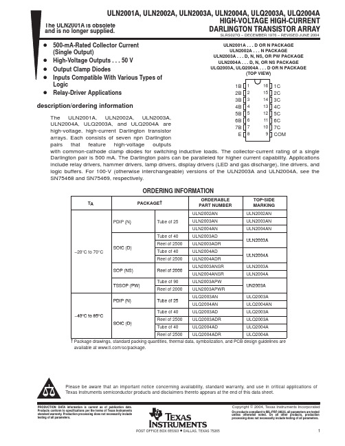
PACKAGING INFORMATIONOrderable Device Status(1)PackageType PackageDrawingPins PackageQtyEco Plan(2)Lead/Ball Finish MSL Peak Temp(3)ULN2001AD OBSOLETE SOIC D16TBD Call TI Call TIULN2001ADR OBSOLETE SOIC D16TBD Call TI Call TIULN2001AN OBSOLETE PDIP N16TBD Call TI Call TIULN2002AD OBSOLETE SOIC D16TBD Call TI Call TIULN2002AN ACTIVE PDIP N1625Pb-Free(RoHS)CU NIPDAU Level-NC-NC-NCULN2002ANE4ACTIVE PDIP N1625Pb-Free(RoHS)CU NIPDAU Level-NC-NC-NCULN2003AD ACTIVE SOIC D1640Green(RoHS&no Sb/Br)CU NIPDAU Level-1-260C-UNLIMULN2003ADE4ACTIVE SOIC D1640Green(RoHS&no Sb/Br)CU NIPDAU Level-1-260C-UNLIMULN2003ADR ACTIVE SOIC D162500Green(RoHS&no Sb/Br)CU NIPDAU Level-1-260C-UNLIMULN2003ADRE4ACTIVE SOIC D162500Green(RoHS&no Sb/Br)CU NIPDAU Level-1-260C-UNLIM ULN2003AJ OBSOLETE CDIP J16TBD Call TI Call TIULN2003AN ACTIVE PDIP N1625Pb-Free(RoHS)CU NIPDAU Level-NC-NC-NCULN2003ANE4ACTIVE PDIP N1625Pb-Free(RoHS)CU NIPDAU Level-NC-NC-NCULN2003ANSR ACTIVE SO NS162000Green(RoHS&no Sb/Br)CU NIPDAU Level-1-260C-UNLIMULN2003ANSRE4ACTIVE SO NS162000Green(RoHS&no Sb/Br)CU NIPDAU Level-1-260C-UNLIMULN2003ANSRG4ACTIVE SO NS162000Green(RoHS&no Sb/Br)CU NIPDAU Level-1-260C-UNLIMULN2003APW ACTIVE TSSOP PW1690Green(RoHS&no Sb/Br)CU NIPDAU Level-1-260C-UNLIM ULN2003APWE4ACTIVE TSSOP PW1690TBD Call TI Call TIULN2003APWG4ACTIVE TSSOP PW1690Green(RoHS&no Sb/Br)CU NIPDAU Level-1-260C-UNLIMULN2003APWR ACTIVE TSSOP PW162000Green(RoHS&no Sb/Br)CU NIPDAU Level-1-260C-UNLIMULN2003APWRE4ACTIVE TSSOP PW162000Green(RoHS&no Sb/Br)CU NIPDAU Level-1-260C-UNLIMULN2004AD ACTIVE SOIC D1640Green(RoHS&no Sb/Br)CU NIPDAU Level-1-260C-UNLIMULN2004ADE4ACTIVE SOIC D1640Green(RoHS&no Sb/Br)CU NIPDAU Level-1-260C-UNLIMULN2004ADR ACTIVE SOIC D162500Green(RoHS&no Sb/Br)CU NIPDAU Level-1-260C-UNLIMULN2004ADRE4ACTIVE SOIC D162500Green(RoHS&no Sb/Br)CU NIPDAU Level-1-260C-UNLIMULN2004AN ACTIVE PDIP N1625Pb-Free(RoHS)CU NIPDAU Level-NC-NC-NCULN2004ANE4ACTIVE PDIP N1625Pb-Free(RoHS)CU NIPDAU Level-NC-NC-NCOrderable Device Status(1)PackageType PackageDrawingPins PackageQtyEco Plan(2)Lead/Ball Finish MSL Peak Temp(3)ULN2004ANSR ACTIVE SO NS162000Green(RoHS&no Sb/Br)CU NIPDAU Level-1-260C-UNLIMULN2004ANSRG4ACTIVE SO NS162000Green(RoHS&no Sb/Br)CU NIPDAU Level-1-260C-UNLIMULQ2003AD ACTIVE SOIC D1640Pb-Free(RoHS)CU NIPDAU Level-2-250C-1YEAR/Level-1-235C-UNLIMULQ2003ADR ACTIVE SOIC D162500Pb-Free(RoHS)CU NIPDAU Level-2-250C-1YEAR/Level-1-235C-UNLIMULQ2003AN ACTIVE PDIP N1625Pb-Free(RoHS)CU NIPDAU Level-NC-NC-NCULQ2004AD ACTIVE SOIC D1640Pb-Free(RoHS)CU NIPDAU Level-2-250C-1YEAR/Level-1-235C-UNLIMULQ2004ADR ACTIVE SOIC D162500Pb-Free(RoHS)CU NIPDAU Level-2-250C-1YEAR/Level-1-235C-UNLIMULQ2004AN ACTIVE PDIP N1625Pb-Free(RoHS)CU NIPDAU Level-NC-NC-NC(1)The marketing status values are defined as follows:ACTIVE:Product device recommended for new designs.LIFEBUY:TI has announced that the device will be discontinued,and a lifetime-buy period is in effect.NRND:Not recommended for new designs.Device is in production to support existing customers,but TI does not recommend using this part in a new design.PREVIEW:Device has been announced but is not in production.Samples may or may not be available.OBSOLETE:TI has discontinued the production of the device.(2)Eco Plan-The planned eco-friendly classification:Pb-Free(RoHS)or Green(RoHS&no Sb/Br)-please check /productcontent for the latest availability information and additional product content details.TBD:The Pb-Free/Green conversion plan has not been defined.Pb-Free(RoHS):TI's terms"Lead-Free"or"Pb-Free"mean semiconductor products that are compatible with the current RoHS requirements for all6substances,including the requirement that lead not exceed0.1%by weight in homogeneous materials.Where designed to be soldered at high temperatures,TI Pb-Free products are suitable for use in specified lead-free processes.Green(RoHS&no Sb/Br):TI defines"Green"to mean Pb-Free(RoHS compatible),and free of Bromine(Br)and Antimony(Sb)based flame retardants(Br or Sb do not exceed0.1%by weight in homogeneous material)(3)MSL,Peak Temp.--The Moisture Sensitivity Level rating according to the JEDEC industry standard classifications,and peak solder temperature.Important Information and Disclaimer:The information provided on this page represents TI's knowledge and belief as of the date that it is provided.TI bases its knowledge and belief on information provided by third parties,and makes no representation or warranty as to the accuracy of such information.Efforts are underway to better integrate information from third parties.TI has taken and continues to take reasonable steps to provide representative and accurate information but may not have conducted destructive testing or chemical analysis on incoming materials and chemicals.TI and TI suppliers consider certain information to be proprietary,and thus CAS numbers and other limited information may not be available for release.In no event shall TI's liability arising out of such information exceed the total purchase price of the TI part(s)at issue in this document sold by TI to Customer on an annual basis.元器件交易网IMPORTANT NOTICETexas Instruments Incorporated and its subsidiaries (TI) reserve the right to make corrections, modifications,enhancements, improvements, and other changes to its products and services at any time and to discontinueany product or service without notice. Customers should obtain the latest relevant information before placingorders and should verify that such information is current and complete. All products are sold subject to TI’s termsand conditions of sale supplied at the time of order acknowledgment.TI warrants performance of its hardware products to the specifications applicable at the time of sale inaccordance with TI’s standard warranty. T esting and other quality control techniques are used to the extent TIdeems necessary to support this warranty. Except where mandated by government requirements, testing of allparameters of each product is not necessarily performed.TI assumes no liability for applications assistance or customer product design. Customers are responsible fortheir products and applications using TI components. T o minimize the risks associated with customer productsand applications, customers should provide adequate design and operating safeguards.TI does not warrant or represent that any license, either express or implied, is granted under any TI patent right,copyright, mask work right, or other TI intellectual property right relating to any combination, machine, or processin which TI products or services are used. Information published by TI regarding third-party products or servicesdoes not constitute a license from TI to use such products or services or a warranty or endorsement thereof.Use of such information may require a license from a third party under the patents or other intellectual propertyof the third party, or a license from TI under the patents or other intellectual property of TI.Reproduction of information in TI data books or data sheets is permissible only if reproduction is withoutalteration and is accompanied by all associated warranties, conditions, limitations, and notices. Reproductionof this information with alteration is an unfair and deceptive business practice. TI is not responsible or liable forsuch altered documentation.Resale of TI products or services with statements different from or beyond the parameters stated by TI for thatproduct or service voids all express and any implied warranties for the associated TI product or service andis an unfair and deceptive business practice. TI is not responsible or liable for any such statements.Following are URLs where you can obtain information on other Texas Instruments products and applicationsolutions:Products ApplicationsAmplifiers Audio /audioData Converters Automotive /automotiveDSP Broadband /broadbandInterface Digital Control /digitalcontrolLogic Military /militaryPower Mgmt Optical Networking /opticalnetworkMicrocontrollers Security /securityTelephony /telephonyVideo & Imaging /videoWireless /wirelessMailing Address:Texas InstrumentsPost Office Box 655303 Dallas, Texas 75265Copyright 2005, Texas Instruments Incorporated。
ULN2003应用电路及中文资料

ULN2003应用电路及中文资料ULN2000、ULN2800是高压大电流达林顿晶体管阵列系列产品,具有电流增益高、工作电压高、温度范围宽、带负载能力强等特点,适应于各类要求高速大功率驱动的系统。
ULN2003A电路是美国Texas Instruments公司和Sprague公司开发的高压大电流达林顿晶体管阵列电路,文中介绍了它的电路构成、特征参数及典型应用。
功率电子电路大多要求具有大电流输出能力,以便于驱动各种类型的负载。
功率驱动电路是功率电子设备输出电路的一个重要组成部分。
在大型仪器仪表系统中,经常要用到伺服电机、步进电机、各种电磁阀、泵等驱动电压高且功率较大的器件。
ULN2000、ULN2800高压大电流达林顿晶体管阵列系列产品就属于这类可控大功率器件,由于这类器件功能强、应用范围语广。
因此,许多公司都生产高压大电流达林顿晶体管阵列产品,从而形成了各种系列产品,ULN2000、ULN2800系列就是美国Texas Instruments公司、美国Sprague公司开发的高压大电流达林顿晶体管阵列产品。
它们的系列型号分类如表1所列,生产2000、2800高压大电流达林顿晶体管阵列系列产品的公司与型号对照表如表2所列。
在上述系列产品中,ULN2000系列能够同时驱动7组高压大电流负载,ULN2800系列则能够同时驱动8组高压大电流负载。
美国Texas Instruments 公司、美国Sprague公司生产的ULN2003A由7组达林顿晶体管阵列和相应的电阻网络以及钳位二极管网络构成,具有同时驱动7组负载的能力,为单片双极型大功率高速集成电路。
以下介绍该电路的构成、性能特征、电参数以及典型应用。
2000、2800高压大电流达林顿晶体管阵列系列中的其它产品的性能特性与应用可参考ULN2003A。
ULN200A电路具有以下特点:●电流增益高(大于1000);●带负载能力强(输出电流大于500mA);●温度范围宽(-40~85℃);●工作电压高(大于50V)。
UL标准明细大全
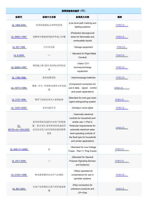
美国保险商实验所(UL)标准号标准中文名称标准英文名称摘要UL 1994-2004 低等级道路标志和照明系统(Low level path marking andlighting systems详细信息。
..UL 2085—1997 易燃和可燃液体用防护性地上贮罐(Protected abovegroundtanks for flammable andcombustible liquids详细信息.。
.UL 201-1994 汽车库设备(Garage equipment 详细信息...UL 6-2000 ()(Standard for Rigid MetalConduit)详细信息.。
.UL 2006—1997 聚四氟乙烯1211的回收/再利用设备(Halon 1211recovery/rechargeequipment详细信息..。
UL 1795-1999 流体按摩浴缸(Hydromassage bathtubs 详细信息..。
UL 1977—1995 数据、信号、控制和电源用元件连接器(Component connectors foruse in data,signal,controland power applications详细信息。
UL 2127-1999 惰性气体清洁剂灭火系统标准(Standard for inert gas cleanagent extinguishing system详细信息.。
UL 1230—2000 业余电影灯具(Amateur movie lights 详细信息..。
UL 60730—2—16A-2002 家用和类似用途的自动电气控制装置。
第2部分:家用和类似用途的浮动式自动电力水位控制设备的特殊要求(Automatic electricalcontrols for household andsimilar use — Part 2:Particular requirements forautomatic electrical waterlevel operating controls ofthe float type for householdand similar applications详细信息..。
ULN2001DS

继电器驱动电路系列/ULN2001DS ULN2001DS 新型三通道继电器驱动电路描述ULN2001DS是单片集成高耐压、大电流达林顿管阵列,电路内部包含三个独立的达林顿管驱动通道。
电路内部设计有续流二极管,可用于驱动继电器等电感性负载。
单个达林顿管集电极可输出100mA电流,将多个通道并联还可实现更高的电流输出能力。
该电路可广泛应用于继电器驱动、照明驱动、显示屏驱动(LED)和逻辑缓冲器。
ULN2001DS的每一路达林顿管串联一个2.7K的基极电阻,在5V的工作电压下可直接与TTL/CMOS 电路连接,可直接处理原先需要标准逻辑缓冲器来处理的数据。
除此之外,ULN2001DS的每一路达林顿管输入级均设计了一个4K的对地下拉电阻,可防止由于单片机状态不定导致的负载误动作。
特点1、100mA集电极输出电流(单路);2、耐高压(50V);3、输入兼容TTL/CMOS逻辑信号;4、广泛应用于继电器驱动。
5、ULN2001DS输入端口集成4K对地下拉电阻。
典型应用1、继电器驱动;2、指示灯驱动;3、显示屏驱动。
引脚排列1B2B3BE3C2C1C订购信息型号 封装类型 温度范围DIP8 Pb‐Free ‐40℃ ~ +85℃ ULN2001DSSOP8 Pb‐Free ‐40℃ ~ +85℃电路原理图(单路达林顿驱动电路))ULN2001DS单路达林顿驱动电路原理图逻辑图1CCOM2C3C引脚定义引脚编号 引脚名称 输入/输出 引脚功能描述1 1B I 1通道输入管脚2 2B I 2通道输入管脚3 3B I 3通道输入管脚4 E ‐ 接地5 COM ‐ 钳位二极管公共端6 3C O 3通道输出管脚7 2C O 2通道输出管脚8 1C O 1通道输出管脚绝对最大额定值(T A =25℃, 除另有规定外)参数符号 值 单位 集电极-发射极电压(6~8脚) V CE 50 V COM 端电压(5脚) V COM 50 V 输入电压(1~3脚) V I 30 V 单路集电极峰值电流I CP 100 mA 输出钳位二极管正向峰值电流 I OK 100 mA 总发射极最大峰值电流I ET ‐300 mA SOP8θJA 160 ℃/W 封装热阻抗(1) (2) (3)DIP8θJA 100 ℃/W 最高工作结温(2)T J 150 ℃ 焊接温度 260 ℃,10s 储存温度范围T stg ‐65 to +150 ℃注:1、最大功耗可按照下述关系计算 P D =(T J ‐T A )/θJA ;2、T J 表示电路工作的结温温度,T A 表示电路工作的环境温度;3、封装热阻的计算方法按照JESD51‐7。
ULN2003原理

在自动化密集的的场合会有很多被控元件如继电器,微型电机,风机,电磁阀,空调,水处理等元件及设备,这些设备通常由CPU所集中控制,由于控制系统不能直接驱动被控元件,这需要由功率电路来扩展输出电流以满足被控元件的电流,电压。
ULN2XXXX高压大电流达林顿晶体管阵列系列产品就属于这类可控大功率器件,由于这类器件功能强、应用范围语广。
因此,许多公司都生产高压大电流达林顿晶体管阵列产品,从而形成了各种系列产品。
838电子ULN2003是什么-原理:LN2003也是一个7路反向器电路,即当输入端为高电平时ULN2003输出端为低电平,当输入端为低电平时ULN2003输出端为高电平,继电器得电吸合。
如图九所示功能特点:高电压输出50V输出钳位二极管输入兼容各种类型的逻辑电路应用继电器驱动器ULN200X逻辑图DISSIPATION RATING TABLE耗散评级表PACK A G E 封装TA=25℃POWERRATING额定功率DERATING FA CTORABOVE功耗系数TA=25℃TA=85℃ POWER RATING 额定功率D950 mW838电子7.6 mW/℃494 mWN1150 mW9.2 mW/℃598 mWelectrical characteristics, 电气特性(除非另有说明)TA = 25℃ (unless otherwise noted)PARAMETER 参数测试图TESTCONDITIONS 测试条件ULN2001A ULN2002A单位最小典型最大最小典型最大-VI( o n )On-state inputvoltage 输入电压6VCE=2V, IC=300mA- - - - - 13VV C E (s at )Collector-emitter saturationvoltage集电极-发射极饱和电压5II=250μA,IC=100mA-0.91.1- 0.9 1.1V II=350μA,IC=200mA- 1 1.3- 1 1.3II=500μA,IC=350mA-1.21.6- 1.2 1.6V F Clamp forwardvoltage 正向钳位电压8IF =350mA-1.72- 1.72VIC E X Collector cutoffcurrent集电极截止电流1VCE =50V, II= 0- - 50- - 50μA 2VCE=5V,TA=7℃II=- 100- - 100-VI=6V- - - - - 500II Off state input 3VCE=55065- 565- μA(o ff ) current关闭状态下输入电流0V,TA=70℃IC=500μA,I I Input current 输入电流4VI =17 V- - - - 0.82 1.25mAI R Clamp reversecurrent 反向钳位电流7VR=50V,TA=70℃- - 100- - 100μA VR =50 V- - 50- - 50h F E Staticforward-currenttransfer ratio 静态正向电流传输比5VCE=2V, IC=350mA100- - - - - -C i Inputcapacitance 输入电容-VI = 0,f =1MHz15251525pFelectrical characteristics, 电气特性(除非另有说明)TA = 25℃ (unless otherwise noted)PARAMETER 参数测试图TESTCONDITIONS 测试条件ULN2003AULN2004A单位最小典型最大最小典型最大VI( on)On stateinputvoltage输入电压66VCE=2VIC=125mA5VIC=200mA- -2.4- - 6IC=250mA- -2.7- - -IC=275mA- - - - - 7IC=300mA- - 3- - -IC=350mA8VC E(s at)ittCollector-emittersaturatio5II = 250μA,IC=100mA- 0.91.1.91.1V II = 350μA, IC - 111 1.3n voltage 集电极发射极饱和电压=200mA.3II = 500μA,IC=350mA- 1.21.61.21.6ICE X Collectorcutoffcurrent集电极截止电流1VCE = 50V, II = 0- -5- 50μA22VCE=50V,TA=70℃II =- -1- - 100-VI=1V- - - - - 500VF Clampforwardvoltage正向钳位电压8IF = 350mA-1.72-1.72VII( off )Off stateinputcurrent关闭状态下输入电流33VCE = 50 V, CE , TA= 70℃ IC = 500μA5065-565- μAII Inputcurrent输入电流4VI = 3.85 V-.931.35- - -mA VI = 5 V- - -.350.5VI = 12 V- - - 1 1.45IR Clampreversecurrent反向钳位电流77VR = 50 V- -5- - 50μA VR = 50 V, TA = 70℃- -1- - 100Ci Inputcapacitance输入电容- VI = 0, f =1MHz-15251525pFelectrical characteristics, 电气特性(除非另有说明)TA = 25℃ (unless otherwise noted)PARAMETER 参数测试图TESTCONDITIONS测试条件ULQ2003AULQ2004A单位最小典型最大最小典型最大VI (o n)On stateinput voltage输入电压6VCE=2VIC=125mA5VIC=200mA- -2.7- - 6IC=250mA- -2.9- - -IC=275mA- - - - - 7IC=300mA- - 3- - -IC=350mA8V CE (s at )ittCollector-emittersaturationvoltage集电极发射极饱和电压5II = 250μA,IC=100mA- 0.91.1.91.1VII = 350μA, IC=200mA- 11.31 1.3II = 500μA,IC=350mA- 1.21.61.21.6IC EX Collectorcutoffcurrent 集电极截止电流1VCE = 50V, II =- -5- 50μA22VCE=50VII =- -1- - 100VI =1V- - - - - 500VF Clampforwardvoltage 正向钳位电压8IF =350mA-1.72-1.72VII( of f)Off stateinput current关闭状态下输入电流3VCE =50V,IC=500μA3065- 5065- μAII Input current输入电流4VI = 3.85V-.931.35- - -mAVI = 5V- - -.350.5VI = 12V- - - 1 1.45IR Clampreversecurrent 反向钳位电流7VR = 50V TA=25℃- -1- - 50μAVR = 50V- -1- - 100Ci Inputcapacitance输入电容- VI = 0, f=1MHz-15251525pFswitching characteristics, 开关特性TA = 25℃PARAMETER 参数TEST CONDITIONS测试条件ULN2001A,ULN2002A,ULN2003A,ULN2004A单位最小典型最大-tP LH Propagation delay time, low-to high-level output传播延迟时间,从低到高输出See Figure 9- 0.251μstP HL Propagation delay time, high-to low-level output 传播延迟时间,从高到低输出See Figure 9- 0.251μsVO H High-level output voltageafter switching 输出高电平电VS=50V, IO≈300mA,See Figure 10VS–20- - mV压switching characteristics over recommended operating conditions (unless otherwise noted)开关特性的建议运行条件(除非另有说明)PARAMETER 参数838电子TEST CONDITIONS测试条件ULQ2003A,ULQ2004A单位最小典型最大tPL H Propagation delay time, low- tohigh-level output 传播延迟时间,从低到高输出See Figure 9- 110μstP HL Propagation delay time, high- tolow-level output 传播延迟时间,从高到低输出See Figure 9- 110μsVO H High-level output voltage afterswitching 输出高电平电压VS=50V, IO≈300mA,See Figure 10VS–50- - mV图一ULN2001A内部电路图图二ULN2002A内部电路图图三ULN2003A ULN2004A ULQ2003A ULQ2004A内部电路图-图1 ICEX测试电路图2 ICEX测试电路图3 ICEX测试电路图4ICEX测试电路图5 hFE, VCE(sat)测试电路图6 VI(on) 测试电路-图四参数测量信息应用电路:图五MOS管加载到输入端图六TTL电路到输入端图七冲区高电流负载图八使用上拉电阻提高驱动电流图九实际应用的UL2003电路图absolute maximum ratings at=25℃ free-air temperature (unless otherwise noted)†绝对最大额定值at=25℃Collector-emitter voltage 集电极-发射极电压50 VClamp diode reverse voltage 钳位二极管的反向电压(见注1 )50 VInput voltage, VI (see Note 1) 输入电压30 VPeak collector current (see Figures 14 and 15)峰值集电极电流500 mAOutput clamp current, IOK .输出钳位电流500 mATotal emitter-terminal current 共发射极端子电流–2.5 AContinuous total power dissipation . 连续总功耗See Dissipation Rating TablePackage thermal impedance, θJA 封装热阻(see Note 2):D package73℃/W N package67℃/W NS package64℃/WOperating free-air temperature range, TA 自由空气的温度范围内ULN200xA–20℃ to 70℃ULQ200xA–40℃ to 85℃Lead temperature 1.6mm(1/16inch)from case for 10 seconds 260℃Storage temperature range, Tstg 储存温度范围–65℃ to 150℃。
ST ULN2001A-ULN2002A ULN2003A-ULN2004A 说明书
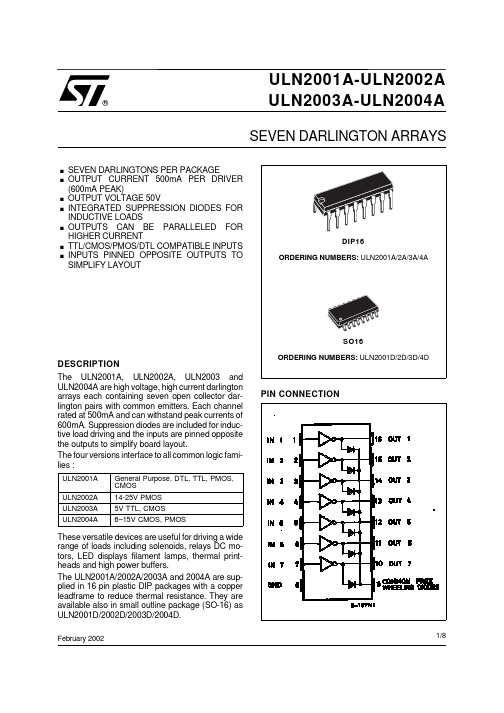
现货库存、技术资料、百科信息、热点资讯,精彩尽在鼎好!ULN2003A-ULN2004AULN2001A-ULN2002A February 2002SEVEN DARLINGTON ARRAYS®.SEVEN DARLINGTONS PER PACKAGE.OUTPUT CURRENT 500mA PER DRIVER (600mA PEAK).OUTPUT VOLTAGE 50V.INTEGRATED SUPPRESSION DIODES FOR INDUCTIVE LOADS.OUTPUTS CAN BE PARALLELED FOR HIGHER CURRENT.TTL/CMOS/PMOS/DTL COMPATIBLE INPUTS .INPUTS PINNED OPPOSITE OUTPUTS TO SIMPLIFY LAYOUTDESCRIPTIONThe ULN2001A, ULN2002A, ULN2003 and ULN2004A are high voltage, high current darlington arrays each containing seven open collector dar-lington pairs with common emitters. Each channel rated at 500mA and can withstand peak currents of 600mA. Suppression diodes are included for induc-tive load driving and the inputs are pinned opposite the outputs to simplify board layout.The four versions interface to all common logic fami-lies :ULN2001A General Purpose, DTL, TTL, PMOS,CMOS ULN2002A 14-25V PMOS ULN2003A 5V TTL, CMOS ULN2004A6–15V CMOS, PMOSThese versatile devices are useful for driving a wide range of loads including solenoids, relays DC mo-tors, LED displays filament lamps, thermal print-heads and high power buffers.The ULN2001A/2002A/2003A and 2004A are sup-plied in 16 pin plastic DIP packages with a copper leadframe to reduce thermal resistance. They are available also in small outline package (SO-16) as ULN2001D/2002D/2003D/2004D.DIP16ORDERING NUMBERS: ULN2001A/2A/3A/4ASO16ORDERING NUMBERS:ULN2001D/2D/3D/4DPIN CONNECTION1/8SCHEMATIC DIAGRAMSeries ULN-2001A(each driver)Series ULN-2002A (each driver)Series ULN-2003A (each driver)Series ULN-2004A (each driver)THERMAL DATASymbol ParameterDIP16SO16Unit R th j-ambThermal Resistance Junction-ambientMax.70120°C/WABSOLUTE MAXIMUM RATINGSSymbol ParameterValue Unit V o Output Voltage50V V in Input Voltage (for ULN2002A/D - 2003A/D - 2004A/D)30V I c Continuous Collector Current 500mA I b Continuous Base Current25mA T amb Operating Ambient Temperature Range – 20 to 85°C T stg Storage Temperature Range – 55 to 150°C T jJunction Temperature150°CELECTRICAL CHARACTERISTICS (T amb = 25o C unless otherwise specified)Symbol Parameter Test Conditions Min.Typ.Max.Unit Fig.I CEX Output Leakage Current V CE = 50VT amb = 70°C, V CE = 50VT amb = 70°Cfor ULN2002AV CE = 50V, V i = 6Vfor ULN2004AV CE = 50V, V i = 1V50100500500µAµAµAµA1a1a1b1bV CE(sat)Collector-emitter SaturationVoltage I C = 100mA, I B = 250µAI C = 200 mA, I B = 350µAI C = 350mA, I B = 500µA0.91.11.31.11.31.6VVV222I i(on)Input Current for ULN2002A, V i = 17Vfor ULN2003A, V i = 3.85Vfor ULN2004A, V i = 5VV i = 12V 0.820.930.3511.251.350.51.45mAmAmAmA3333I i(off)Input Current T amb = 70°C, I C = 500µA5065µA4 V i(on)Input Voltage V CE = 2Vfor ULN2002AI C = 300mA for ULN2003AI C = 200mAI C = 250mAI C = 300mA for ULN2004AI C = 125mAI C = 200mAI C = 275mAI C = 350mA 132.42.735678V5h FE DC Forward Current Gain for ULN2001AV CE = 2V, I C = 350mA10002 C i Input Capacitance1525pFt PLH Turn-on Delay Time0.5 V i to 0.5 V o0.251µst PHL Turn-off Delay Time0.5 V i to 0.5 V o0.251µsI R Clamp Diode Leakage Current V R = 50VT amb = 70°C, V R = 50V50100µAµA66V F Clamp Diode Forward Voltage I F = 350mA 1.72V7TEST CIRCUITSFigure 1a.Figure 1b.Figure 2.Figure 3.Figure 4.Figure 5.Figure 6.Figure 7.0100200300400500Ib(µA)100200300400500Ic (mA)Tj=25˚CD96IN453TYPICALMaxFigure 8: Collector Current versus Input Current0.00.5 1.0 1.5Vce(sat)100200300400500Ic (mA)Tj=25˚CD96IN454MaxTYPICALFigure 9: Collector Current versus SaturationVoltage20406080DC100200300400500Ic peak (mA)Tamb=70˚C (DIP16)765432NUMBER OF ACTIVE OUTPUT D96IN451Figure 10: Peak Collector Current versus DutyCycle020*********DC100200300400500Ic peak (mA)D96IN452A7532NUMBER OF ACTIVE OUTPUTTamb=70˚C (SO16)Figure 11: Peak Collector Current versus DutyCycleDIP16DIM.mm inch MIN.TYP.MAX.MIN.TYP.MAX.a10.510.020B 0.771.650.0300.065b 0.50.020b10.250.010D 200.787E 8.50.335e 2.540.100e317.780.700F 7.10.280I 5.10.201L 3.30.130Z1.270.050OUTLINE ANDMECHANICAL DATASO16 NarrowDIM.mm inch MIN.TYP.MAX.MIN.TYP.MAX.A 1.750.069a10.10.250.0040.009a2 1.60.063b 0.350.460.0140.018b10.190.250.0070.010C 0.50.020c145˚ (typ.)D (1)9.8100.3860.394E 5.8 6.20.2280.244e 1.270.050e38.890.350F (1) 3.840.1500.157G 4.6 5.30.1810.209L 0.4 1.270.0160.050M 0.620.024S(1) D and F do not include mold flash or protrusions. Mold flash or potrusions shall not exceed 0.15mm (.006inch).OUTLINE AND MECHANICAL DATA8˚(max.)Information furnished is believed to be accurate and reliable. However, STMicroelectronics assumes no responsibility for the conse-quences of use of such information nor for any infringement of patents or other rights of third parties which may result from its use. No license is granted by implication or otherwise under any patent or patent rights of STMicroelectronics. Specification mentioned in this publication are subject to change without notice. This publication supersedes and replaces all information previously supplied. STMi-croelectronics products are not authorized for use as critical components in life support devices or systems without express written approval of STMicroelectronics.The ST logo is a registered trademark of STMicroelectronics© 2002 STMicroelectronics – Printed in Italy – All Rights ReservedSTMicroelectronics GROUP OF COMPANIESAustralia - Brazil - Canada - China - Finland - France - Germany - Hong Kong - India - Israel - Italy - Japan - Malaysia - Malta - Morocco -Singapore - Spain - Sweden - Switzerland - United Kingdom - United States.。
达林顿管ULN2003 ULN2004与之相配的KEC

达林顿管ULN2003/2004与之相配的KECAmeya360ULN2003/2004达林顿晶体管替代介绍应用洗衣机冰箱空调因为大家接触的最多的ULN2003/2004,下面主要介绍UNL2003/2004然后推荐KEC 两个与之相匹配并可以替换的物料,可以为大家节省成本,提供足够物料选型。
ULN2003介绍高耐压、大电流达林顿阵列,由七个硅NPN 达林顿管组成该电路的特点如下:ULN2003 的每一对达林顿都串联一个2.7K 的基极电阻,在5V 的工作电压下它能与TTL 和CMOS 电路直接相连,可以直接处理原先需要标准逻辑缓冲器来处理的数据。
ULN2003 工作电压高,工作电流大,灌电流可达500mA,并且能够在关态时承受50V 的电压,输出还可以在高负载电流并行运行。
ULN2003输入电压=5V,适用于TTL COMS,由达林顿管组成驱动电路。
通常单片机驱动ULN2003时,上拉2K的电阻较为合适,同时,COM引脚应该悬空或接电源。
ULN2003与ULN2004的不同之处两个实现的功能基本一样都是输出电压50V 输出电流500ma,不同处回路的电阻有差别,ULN2003是2.7k,ULN2004是10.5k。
灵敏度也有差别,简单讲2003适于5V TTL、CMOS 输入,2004适宜6-15V PMOS CMOS输入。
ULN2003与ULN2004功能集成达林顿管IC,内部集成的一个消线圈反电动势的二极管,双列16脚封装,NPN 晶体管矩阵,最大驱动电压=50V,电流=500mA,它的输出端允许通过电流为200mA,饱和压降VCE 约1V左右,耐压BVCEO 约为36V。
用户输出口的外接负载可根据以上参数估算。
采用集电极开路输出,输出大电流驱动阵列, 工作电压高、温度范围宽、带负载能力强等特点,多用于单片机、智能仪表、PLC、数字量输出卡等控制电路中。
故可直接驱动继电器或固体继电器,直流电机,LED显示器、伺服电机、步进电机、各种电磁阀、泵等驱动电压高且功率较大的器件也可直接驱动低压灯泡。
uln2004a原理

**ULN2004A原理如下**:
ULN2004A是一种达林顿晶体管阵列,由七个晶体管组成一个达林顿管,其输出电阻非常低,适合驱动继电器,工作温度范围为-40℃至+125℃。
它内部包含有七个独立的恒流电路,每个可以驱动25V/2.5A的继电器。
每个单独的达林顿管都集成了一个大功率晶体三极管,使得每个输出级可以输出更大的电流,因此可以直接驱动一些简单的开关或者控制电路。
其工作原理主要是通过接受控制器的信号,然后控制输出继电器的开关状态。
当控制信号到来时,会进入反相器,然后反相器的输出则控制驱动器,而驱动器则会打开或关闭连接的继电器。
ULN2004A可以将微弱的信号增强到足够的电压来闭合或断开器件。
因此,它常用于复杂的电路中控制开关或通断电路。
对于用户来说,其具体的应用场景主要取决于系统的需要以及设备本身的能力。
如果需要控制大电流的场合,需要选择适合的大功率型芯片。
如果需要扩展输出的驱动电流或电压的能力,可能需要使用到其他的外部元件。
在设计PCB时,需要考虑到电源噪声的问题,可能需要添加去耦电容等。
以上内容仅供参考,建议查阅厂家提供的技术手册或咨询相关专家,以获取更全面和准确的信息。
uln2004an工作原理
uln2004an工作原理
ULN2004AN是一种高电压和高电流兼容的继电器驱动器,可以用来驱动高电压和高电流的负载,如继电器、步进电机等。
其工作原理如下:
1. ULN2004AN是由7个固态开关(电流驱动)组成的集成电路芯片,每个开关可以控制一个独立的输出通道。
2. ULN2004AN采用了达林顿(TTL/CMOS)输入和大功率的开关驱动输出,即输入控制小电流,输出驱动大电流。
3. ULN2004AN的输入电流非常小,在TTL逻辑电平范围内,可以被微控制器或其他数字电路直接驱动。
其输入引脚集成了输入电流限制电阻,可以通过连接外部电阻来设置输入电阻。
4. ULN2004AN的输出引脚可以直接连接到电源和负载,电源上的电压可以高达50V,输出电流最大为500mA。
5. 当输入信号为低电平时,相应的输出引脚将被拉到低电压,负载不导通。
当输入信号为高电平时,输出引脚将被拉到高电压,负载导通。
6. ULN2004AN还具有短路保护和过热保护功能,当负载短路或工作时温度过高时,芯片会自动保护。
总之,ULN2004AN可以通过输入信号控制输出通道的导通和断开,同时可以提供高电压和高电流来驱动负载。
它非常适用于驱动继电器、步进电机等需要较大电流和电压的应用场合。
ULN2003A应用
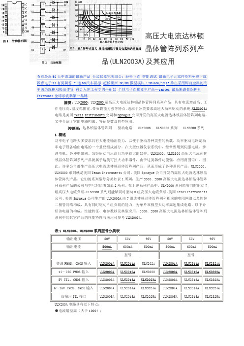
高压大电流达林顿晶体管阵列系列产品(ULN2003A)及其应用查看最近90天中添加的最新产品台式仪器完美组合:轻松互连智能调试最新电子元器件资料免费下载派睿电子TI有奖问答 - 送3D汽车鼠标超低噪声 DC/DC微型模块 LTM4606/12IR推出采用焊前金属的汽车级绝缘栅双极晶体管符合人体工程学的平衡器全球电子连接器生产商—samtec最新断路器保护套Tektronix全球示波器第一品牌摘要:ULN2000、ULN2800是高压大电流达林顿晶体管阵列系列产品,具有电流增益高、工作电压高、温度范围宽、带负载能力强等特点,适应于各类要求高速大功率驱动的系统。
ULN2003A电路是美国Texas Instruments公司和Sprague公司开发的高压大电流达林顿晶体管阵列电路,文中介绍了它的电路构成、特征参数及典型应用。
关键词:达林顿晶体管阵列驱动电路 ULN2003 ULN2000系列 ULN2800系列1 概述功率电子电路大多要求具有大电流输出能力,以便于驱动各种类型的负载。
功率驱动电路是功率电子设备输出电路的一个重要组成部分。
在大型仪器仪表系统中,经常要用到伺服电机、步进电机、各种电磁阀、泵等驱动电压高且功率较大的器件。
ULN2000、ULN2800高压大电流达林顿晶体管阵列系列产品就属于这类可控大功率器件,由于这类器件功能强、应用范围语广。
因此,许多公司都生产高压大电流达林顿晶体管阵列产品,从而形成了各种系列产品,ULN2000、ULN2800系列就是美国Texas Instruments公司、美国Sprague公司开发的高压大电流达林顿晶体管阵列产品。
它们的系列型号分类如表1所列,生产2000、2800高压大电流达林顿晶体管阵列系列产品的公司与型号对照表如表2所列。
在上述系列产品中,ULN2000系列能够同时驱动7组高压大电流负载,ULN2800系列则能够同时驱动8组高压大电流负载。
美国Texas Instruments公司、美国Sprague公司生产的ULN2003A由7组达林顿晶体管阵列和相应的电阻网络以及钳位二极管网络构成,具有同时驱动7组负载的能力,为单片双极型大功率高速集成电路。
- 1、下载文档前请自行甄别文档内容的完整性,平台不提供额外的编辑、内容补充、找答案等附加服务。
- 2、"仅部分预览"的文档,不可在线预览部分如存在完整性等问题,可反馈申请退款(可完整预览的文档不适用该条件!)。
- 3、如文档侵犯您的权益,请联系客服反馈,我们会尽快为您处理(人工客服工作时间:9:00-18:30)。
2
V7
3/8
ULN2001A - ULN2002A - ULN2003A - ULN2004A
TEST CIRCUITS Figure 1a.
Figure 1b.
Figure 2.
Figure 3.
Figure 4.
Figure 5.
Figure 6.
Figure 7.
4/8
ULN2001A - ULN2002A - ULN2003A - ULN2004A
Series ULN-2002A (each driver)
Series ULN-2003A (each driver)
Series ULN-2004A (each driver)
ABSOLUTE MAXIMUM RATINGS
Symbol Vo Vin Ic Ib Tamb Tstg Tj
Parameter Output Voltage Input Voltage (for ULN2002A/D - 2003A/D - 2004A/D) Continuous Collector Current Continuous Base Current Operating Ambient Temperature Range Storage Temperature Range Junction Temperature
These versatile devices are useful for driving a wide range of loads including solenoids, relays DC motors, LED displays filament lamps, thermal printheads and high power buffers.
ULN2001A-ULN2002A
®
ULN2003A-ULN2004A
SEVEN DARLINGTON ARRAYS
. SEVEN DARLINGTONS PER PACKAGE . OUTPUT CURRENT 500mA PER DRIVER
(600mA PEAK)
. OUTPUT VOLTAGE 50V . INTEGRATED SUPPRESSION DIODES FOR
Ic peak (mA)
500
D96IN451
NUMBER OF ACTIVE OUTPUT
7 65 4 3
2
400
300 Tamb=70˚C
(DIP16) 200
100
0
0
20
40
60
80
DC
Figure 11: Peak Collector Current versus Duty Cycle
Ic peak (mA)
for ULN2001A VCE = 2V, IC = 350mA
0.5 Vi to 0.5 Vo
0.5 Vi to 0.5 Vo
VR = 50V Tamb = 70°C, VR = 50V
IF = 350mA
50 1000
0.9 1.1 1.3 0.82 0.93 0.35 1 65
15 0.25 0.25
INDUCTIVE LOADS
. OUTPUTS CAN BE PARALLELED FOR HIGHER CURRENT
. TTL/CMOS/PMOS/DTL COMPATIBLE INPUTS . INPUTS PINNED OPPOSITE OUTPUTS TO
SIMPLIFY LAYOUT
DIP16 ORDERING NUMBERS: ULN2001A/2A/3A/4A
Test Conditions
VCE = 50V Tamb = 70°C, VCE = 50V
Min. Typ.
VCE(sat) Ii(on)
Ii(off) Vi(on)
hFE Ci tPLH tPHL IR VF
Collector-emitter Saturation Voltage Input Current
The four versions interface to all common logic families :
ULN2001A ULN2002A
General Purpose, DTL, TTL, PMOS, CMOS
14-25V PMOS
ULN2003A ULN2004A
5V TTL, CMOS 6–15V CMOS, PMOS
Tamb = 70°C, IC = 500µA
VCE = 2V for ULN2002A
IC = 300mA for ULN2003A
IC = 200mA IC = 250mA IC = 300mA for ULN2004A IC = 125mA IC = 200mA IC = 275mA IC = 350mA
inch TYP. MAX.
a1 0.51
0.020
B 0.77
1.65 0.030
0.065
b
0.5
0.020
b1
0.25
0.010
D
20
0.787
E
8.5
0.335
e
2.54
0.100
e3
17.78
0.700
F
7.1
0.280
I
5.1
0.201
L
3.3
0.130
Z
1.27
0.050
OUTLINE AND MECHANICAL DATA
DIP16
6/8
ULN2001A - ULN2002A - ULN2003A - ULN2004A
mm DIM.
inch
MIN. TYP. MAX. MIN. TYP. MAX.
A
1.75
0.069
a1 0.1
0.25 0.004
0.009
a2
1.6
0.063
b 0.35
0.46 0.014
0.018
THERMAL DATA
Symbol Rth j-amb
Parameter Thermal Resistance Junction-ambient
Value
Unit
50
V
30
V
500
mA
25
mA
– 20 to 85
°C
– 55 to 150
°C
150
°C
Max.
DIP16 70
SO16 120
Unit °C/W
DESCRIPTION
The ULN2001A, ULN2002A, ULN2003 and ULN2004A are high voltage, high current darlington arrays each containing seven open collector darlington pairs with common emitters. Each channel rated at 500mA and can withstand peak currents of 600mA. Suppression diodes are included for inductive load driving and the inputs are pinned opposite the outputs to simplify board layout.
1.7
Max.
50 100
Unit Fig. µA 1a µA 1a
500 µA 1b
பைடு நூலகம்
500 µA 1b
1.1
V
2
1.3
V
2
1.6
V
2
1.25 mA 3 1.35 mA 3 0.5 mA 3 1.45 mA 3
µA 4
V5
13
2.4 2.7 3
5 6 7 8
2
25 pF
1
µs
1
µs
50 µA 6 100 µA 6
February 2002
SO16 ORDERING NUMBERS: ULN2001D/2D/3D/4D
PIN CONNECTION
1/8
ULN2001A - ULN2002A - ULN2003A - ULN2004A
SCHEMATIC DIAGRAM
Series ULN-2001A (each driver)
Tamb = 70°C for ULN2002A
VCE = 50V, Vi = 6V for ULN2004A
VCE = 50V, Vi = 1V
IC = 100mA, IB = 250µA IC = 200 mA, IB = 350µA IC = 350mA, IB = 500µA
for ULN2002A, Vi = 17V for ULN2003A, Vi = 3.85V for ULN2004A, Vi = 5V Vi = 12V
The ULN2001A/2002A/2003A and 2004A are supplied in 16 pin plastic DIP packages with a copper leadframe to reduce thermal resistance. They are available also in small outline package (SO-16) as ULN2001D/2002D/2003D/2004D.
7/8
ULN2001A - ULN2002A - ULN2003A - ULN2004A
Information furnished is believed to be accurate and reliable. However, STMicroelectronics assumes no responsibility for the consequences of use of such information nor for any infringement of patents or other rights of third parties which may result from its use. No license is granted by implication or otherwise under any patent or patent rights of STMicroelectronics. Specification mentioned in this publication are subject to change without notice. This publication supersedes and replaces all information previously supplied. STMicroelectronics products are not authorized for use as critical components in life support devices or systems without express written approval of STMicroelectronics.
