AD546KN中文资料
运算放大器(AD549)应用中文技术资料

极低偏置电流运算放大器AD5491 概述AD549是具有极低输入偏置电流的单片电路静电计型运算放大器。
为达到高精度的目的,输入偏置电压和输入偏置电压漂移均通过激光调节。
这种极低输入电流性能由ADI公司专有的topgate工艺技术完成。
该技术可以制造与具有极低输入电流的JFET并与双极性电路隔离的集成运放。
输入级具有1015Ω的共模阻抗,其输入电流与共模电压无关。
AD549适用于低输入电流和低输入偏置电压的场合。
它特别适合用作各种电流输出的传感器,如光电二极管、光电倍增管以及氧气传感器等的前置放大器。
该产品也可用作精密积分器或低衰减采样保持器。
AD549的封装与标准FET和静电计运算放大器兼容,因此用户花少量成本即可对系统升级,提高已有系统的性能。
AD549有TO-99密封封装。
金属外壳与8管脚相连,使得金属外壳与同样电压的输入终端独立连接,达到降低外壳泄漏的目的。
AD549具有四种性能等级。
其中J、K和L型号的温度范围是0℃到70℃。
S型号专用于军事,其温度范围:-55℃到125℃。
AD549的输入电流在整个共模输入电压范围内都得到保证,其输入失调电压和漂移由激光分别调节到0.25mV和5μV/℃(AD549K);1mV和20μV/℃(AD549J)。
700μA的最大静态电流使输入电流和偏置电压的热效应降到最低。
模拟性能包括1MHz的均匀增益带宽和3V/μs的压摆率。
当输入为10V时,建立时间是5μs 到0.01%。
2 AD549的引脚及特性参数图一所示是AD549的引脚图,表一所示是其特性参数。
图一AD549引脚图表一AD549的主要特性nV/ nV/ nV/ nV/3 AD549的工作原理3.1 最小化输入电流AD549具有很小的输入电流和失调电压。
在实际应用中应谨慎考虑如何使用放大器可以减小输入电流。
为减小输入电流,该放大器的工作温度应尽可能低。
像其他JFET输入放大器一样,AD549的输入电流对芯片温度很敏感,上升斜率因子为每10℃的2.3。
2N5460中文资料
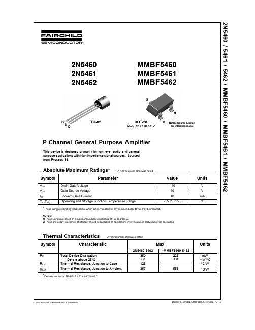
D
NOTE: Source & Drain are interchangeable
P-Channel General Purpose Amplifier
This device is designed primarily for low level audio and general purpose applications with high impedance signal sources. Sourced from Process 89.
5
Power Dissipation vs. Ambient Temperature
P D - POWER DISSIPATION (mW) 350 300 250 200 150 100 50 0 0 25 50 75 100 TEMPERATURE (ºC) 125 150
TO-92 SOT-23
元器件交易网
2N5460 / 5461 / 5462 / MMBF5460 / MMBF5461 / MMBF5462
P-Channel General Purpose Amplifier
(continued)
Electrical Characteristics
Symbol Parameter
元器件交易网
TRADEMARKS
The following are registered and unregistered trademarks Fairchild Semiconductor owns or is authorized to use and is not intended to be an exhaustive list of all such trademarks.
AD7656中文资料

250 kSPS 、六通道、同步采样、双极性16/14/12-位 ADCAD7656/AD7657/AD7658Rev. D Information furnished by Analog Devices is believed to be accurate and reliable. However , no responsibility is assumed by Analog Devices for its use, nor for any infringements of patents or other rights of third parties that may result from its use. Speci cations subject to change without notice. No license is granted by implication or otherwise under any patent or patent rights of Analog Devices. T rademarks and registered trademarks are the property of their respective owners.One Technology Way, P.O.Box 9106, Norwood, MA 02062-9106, U.S.A.Tel: 781.329.4700 Fax: 781.461.3113 2006–2012 Analog Devices, Inc. All rights reserved.功能框图V SSDGNDV DDREFCONVST ACONVST B CONVST C OUTPUT DRIVERSOUTPUT DRIVERSOUTPUT DRIVERSOUTPUT DRIVERSCONTROL LOGICBUFBUFBUFAGNDT/HT/H T/H T/HT/HT/HCLK OSCAV CCDV CCV1V2V3V4V5V6SER/PAR CSV DRIVE STBYDOUT ADOUT BDOUT C SCLKRD WRDATA/CONTROL LINES 05020-001AD7656/AD7657/AD765816-/14-/12-BIT SAR16-/14-/12-BIT SAR16-/14-/12-BIT SAR16-/14-/12-BIT SAR16-/14-/12-BIT SAR16-/14-/12-BIT SAR图1.-1受美国专利第6,731,232号保护。
AD546资料

*Covered by Patent No. 4,639,683.
REV. A
Information furnished by Analog Devices is believed to be accurate and reliable. However, no responsibility is assumed by Analog Devices for its use, nor for any infringements of patents or other rights of third parties which may result from its use. No license is granted by implication or otherwise under any patent or patent rights of Analog Devices.
Conditions
VCM = 0 V VCM = ± 10 V VCM = 0 V VCM = ± 10 V VCM = 0 V VCM = 0 V
TMIN–TMAX
AD546J
AD546K
Min Typ Max Min Typ Max
0.2 1 0.1 1
40 40 0.17
13
0.2
0.5
0.2
80
76
–12
运算放大器(AD549)应用中文技术资料

极低偏置电流运算放大器AD5491 概述AD549是具有极低输入偏置电流的单片电路静电计型运算放大器。
为达到高精度的目的,输入偏置电压和输入偏置电压漂移均通过激光调节。
这种极低输入电流性能由ADI公司专有的topgate工艺技术完成。
该技术可以制造与具有极低输入电流的JFET并与双极性电路隔离的集成运放。
输入级具有1015Ω的共模阻抗,其输入电流与共模电压无关。
AD549适用于低输入电流和低输入偏置电压的场合。
它特别适合用作各种电流输出的传感器,如光电二极管、光电倍增管以及氧气传感器等的前置放大器。
该产品也可用作精密积分器或低衰减采样保持器。
AD549的封装与标准FET和静电计运算放大器兼容,因此用户花少量成本即可对系统升级,提高已有系统的性能。
AD549有TO-99密封封装。
金属外壳与8管脚相连,使得金属外壳与同样电压的输入终端独立连接,达到降低外壳泄漏的目的。
AD549具有四种性能等级。
其中J、K和L型号的温度范围是0℃到70℃。
S型号专用于军事,其温度范围:-55℃到125℃。
AD549的输入电流在整个共模输入电压范围内都得到保证,其输入失调电压和漂移由激光分别调节到0.25mV和5μV/℃(AD549K);1mV和20μV/℃(AD549J)。
700μA的最大静态电流使输入电流和偏置电压的热效应降到最低。
模拟性能包括1MHz的均匀增益带宽和3V/μs的压摆率。
当输入为10V时,建立时间是5μs 到0.01%。
2 AD549的引脚及特性参数图一所示是AD549的引脚图,表一所示是其特性参数。
图一AD549引脚图表一AD549的主要特性nV/ nV/ nV/ nV/3 AD549的工作原理3.1 最小化输入电流AD549具有很小的输入电流和失调电压。
在实际应用中应谨慎考虑如何使用放大器可以减小输入电流。
为减小输入电流,该放大器的工作温度应尽可能低。
像其他JFET输入放大器一样,AD549的输入电流对芯片温度很敏感,上升斜率因子为每10℃的2.3。
宽带通信接收机的ADC参数
宽带通信接收机的ADC参数技术分类:模拟设计通信 | 2006-05-30来源:Maxim | Dallas > 应用笔记 >宽带接收机设计需要采用外差体系结构,以便在有干扰或者阻塞信号的情况下获得最佳灵敏度。
以蜂窝cdma2000®多载波接收机设计为例,本文讨论某些影响模数转换器(ADC)选择的重要参数—IF频率、接收机模拟功率增益、信号带宽和ADC采样时钟频率等参数。
通过这一设计实例,还讨论了以下ADC参数:满量程(FS)功率、小信号噪声底(SSNF)、信噪比(SNR)和无杂散动态范围(SFDR)。
16位、80Msps MAX19586 ADC在当今所有的ADC中具有最低的噪声底,在接收机设计中不需要降低增益或采用自动增益控制(AGC)。
MAX19586优异的噪声性能以及SFDR性能能够满足甚至由于此类应用对ADC的要求。
外差接收机包括一级混频器(LO1),将RF波形转换为第一中频(IF)信号(图1)。
可以对这一IF信号进行数字化处理或送入第二级混频器(LO2),将其转换为频率更低的IF。
把信号转换到更低IF利用了ADC良好的噪声和线性性能,这些性能一般在低频输入时才能够获得。
采用欠采样技术数字化真实的带通信号,其采样速率在信号带宽内符合Nyquist定律,而不针对其绝对频率。
使用这一方法,ADC对真实信号进行数字化,然后利用数字信号处理(DSP)技术,在数字域将其转换为合成分量。
这种方法的优势在于能够降低硬件的复杂性和成本,因为欠采样技术承担了部分下变频任务。
但是,这种体系结构需要时钟速率较高的ADC,以及较宽的动态范围(即低噪声和高线性)。
欠采样技术除了这些优点之外,一个重要的缺点是噪声混叠,如果输入信号没有进行充分的带宽限制,将对带内的混叠噪声进行数字化处理并和有用信号一起转换成基带信号,噪声混叠将导致ADC的SNR下降。
图1. 利用特性曲线确定超外差接收机的ADC NF、接收机功率增益、最大阻塞电平的最佳平衡点。
onsemi 2n5460-d 数据表 说明书

To learn more about onsemi™, please visit our website atON SemiconductorIs Now2N5460, 2N5461, 2N5462 JFET AmplifierP−Channel − DepletionFeatures•Pb−Free Packages are Available*MAXIMUM RATINGSRating Symbol Value Unit Drain − Gate Voltage V DG40Vdc Reverse Gate − Source Voltage V GSR40Vdc Forward Gate Current I G(f)10mAdcTotal Device Dissipation @ T A = 25°C Derate above 25°C P D3502.8mWmW/°CJunction Temperature Range T J−65 to +135°CStorage Channel Temperature Range T stg−65 to +150°C Stresses exceeding Maximum Ratings may damage the device. Maximum Ratings are stress ratings only. Functional operation above the Recommended Operating Conditions is not implied. Extended exposure to stresses above the Recommended Operating Conditions may affect device reliability.*For additional information on our Pb−Free strategy and soldering details, please download the ON Semiconductor Soldering and Mounting Techniques Reference Manual, SOLDERRM/D.Preferred devices are recommended choices for future use and best overall value.See detailed ordering and shipping information in the package dimensions section on page 2 of this data sheet.ORDERING INFORMATIONELECTRICAL CHARACTERISTICS (T A = 25°C unless otherwise noted)CharacteristicSymbolMinTypMaxUnitOFF CHARACTERISTICS Gate −Source Breakdown Voltage (I G = 10 m Adc, V DS = 0)2N5460, 2N5461, 2N5462V (BR)GSS 40−−Vdc Gate Reverse Current(V GS = 20 Vdc, V DS = 0)2N5460, 2N5461, 2N5462(V GS = 30 Vdc, V DS = 0)(V GS = 20 Vdc, V DS = 0, T A = 100°C)2N5460, 2N5461, 2N5462(V GS = 30 Vdc, V DS = 0, T A = 100°C)I GSS−−−− 5.01.0nAdc m Adc Gate −Source Cutoff Voltage2N5460(V DS = 15 Vdc, I D = 1.0 m Adc)2N54612N5462V GS(off)0.751.01.8−−− 6.07.59.0VdcGate −Source Voltage(V DS = 15 Vdc, I D = 0.1 mAdc)2N5460(V DS = 15 Vdc, I D = 0.2 mAdc)2N5461(V DS = 15 Vdc, I D = 0.4 mAdc)2N5462V GS0.50.81.5−−−4.04.56.0VdcON CHARACTERISTICSZero−Gate −Voltage Drain Current2N5460(V DS = 15 Vdc, V GS = 0, f = 1.0 kHz)2N54612N5462I DSS−1.0−2.0−4.0−−−−5.0−9.0−16mAdcSMALL−SIGNAL CHARACTERISTICS Forward Transfer Admittance2N5460(V DS = 15 Vdc, V GS = 0, f = 1.0 kHz)2N54612N5462⎪y fs ⎪100015002000−−−400050006000m mhosOutput Admittance (V DS = 15 Vdc, V GS = 0, f = 1.0 kHz)⎪y os ⎪−−75m mhos Input Capacitance (V DS = 15 Vdc, V GS = 0, f = 1.0 MHz)C iss − 5.07.0pF Reverse Transfer Capacitance (V DS = 15 Vdc, V GS = 0, f = 1.0 MHz)C rss−1.02.0pFORDERING INFORMATIONDevicePackage Shipping †2N5460TO−921000 Units / Box 2N5460G TO−92(Pb−Free)2N5461TO−922N5461G TO−92(Pb−Free)2N5461RLRA TO−922000 / Tape & Reel 2N5461RLRAG TO−92(Pb−Free)2N5462TO−921000 Units / Box 2N5462GTO−92(Pb−Free)†For information on tape and reel specifications, including part orientation and tape sizes, please refer to our Tape and Reel Packaging Specifications Brochure, BRD8011/D.Y f s F O R W A R D T R A N S F E R A D M I T T A N C E (m h o s )m Y f s F O R W A R D T R A N S F E R A D M I T T A N C E (m h o s )m DRAIN CURRENT versus GATESOURCE VOLTAGEFORWARD TRANSFER ADMITTANCEversus DRAIN CURRENTI D , D R A I N C U R R E N T (m A )Y f s F O R W A R D T R A N S F E R A D M I T T A N C E (m h o s )m 4.0V GS , GATE−SOURCE VOLTAGE (VOLTS)Figure 1. V GS(off) = 2.0 VI D , DRAIN CURRENT (mA)I D , D R A I N C U R R E N T(m A )1010000V GS , GATE−SOURCE VOLTAGE (VOLTS)Figure 2. V GS(off) = 4.0 VI D , DRAIN CURRENT (mA)I D , D R A I NC U R RE N T (m A )1610000V GS , GATE−SOURCE VOLTAGE (VOLTS)Figure 3. V GS(off) = 5.0 V I D , DRAIN CURRENT (mA)Figure 4. V GS(off) = 2.0 VFigure 5. V GS(off) = 4.0 VFigure 6. V GS(off) = 5.0 V05007001000200030005000700050070010002000300050007000100010r o s s , O U T P U T R E S I S T A N C E (k o h m s )R S , SOURCE RESISTANCE (k Ohms)Figure 9. Noise Figure versusSource ResistanceFigure 10. Equivalent Low Frequency Circuit20305070100200300500700NOTE:1.Graphical data is presented for dc conditions. Tabular data is given for pulsed conditions (Pulse Width = 630 ms,Duty Cycle = 10%).*C osp is C oss in parallel with Series Combination of C iss and C rss .v COMMON SOURCEy PARAMETERS FOR FREQUENCIESBELOW 30 MHz y is = j W C issy os = j W C osp * + 1/r oss y fs = y fs |y rs = −j W C rssPACKAGE DIMENSIONSSTYLE 7:PIN 1.SOURCE2.DRAIN3.GATETO−92CASE 29−11ISSUE ALNOTES:1.DIMENSIONING AND TOLERANCING PER ANSI Y14.5M, 1982.2.CONTROLLING DIMENSION: INCH.3.CONTOUR OF PACKAGE BEYOND DIMENSION R IS UNCONTROLLED.4.LEAD DIMENSION IS UNCONTROLLED IN P AND BEYOND DIMENSION K MINIMUM.DIMMIN MAX MIN MAX MILLIMETERSINCHES A 0.1750.205 4.45 5.20B 0.1700.210 4.32 5.33C 0.1250.165 3.18 4.19D 0.0160.0210.4070.533G 0.0450.055 1.15 1.39H 0.0950.105 2.42 2.66J 0.0150.0200.390.50K 0.500−−−12.70−−−L 0.250−−− 6.35−−−N 0.0800.105 2.04 2.66P −−−0.100−−− 2.54R 0.115−−− 2.93−−−V0.135−−−3.43−−−ON Semiconductor and are registered trademarks of Semiconductor Components Industries, LLC (SCILLC). SCILLC reserves the right to make changes without further notice to any products herein. SCILLC makes no warranty, representation or guarantee regarding the suitability of its products for any particular purpose, nor does SCILLC assume any liability arising out of the application or use of any product or circuit, and specifically disclaims any and all liability, including without limitation special, consequential or incidental damages.“Typical” parameters which may be provided in SCILLC data sheets and/or specifications can and do vary in different applications and actual performance may vary over time. All operating parameters, including “Typicals” must be validated for each customer application by customer’s technical experts. SCILLC does not convey any license under its patent rights nor the rights of others. SCILLC products are not designed, intended, or authorized for use as components in systems intended for surgical implant into the body, or other applications intended to support or sustain life, or for any other application in which the failure of the SCILLC product could create a situation where personal injury or death may occur. Should Buyer purchase or use SCILLC products for any such unintended or unauthorized application, Buyer shall indemnify and hold SCILLC and its officers, employees, subsidiaries, affiliates,and distributors harmless against all claims, costs, damages, and expenses, and reasonable attorney fees arising out of, directly or indirectly, any claim of personal injury or death associated with such unintended or unauthorized use, even if such claim alleges that SCILLC was negligent regarding the design or manufacture of the part. SCILLC is an Equal Opportunity/Affirmative Action Employer. This literature is subject to all applicable copyright laws and is not for resale in any manner.PUBLICATION ORDERING INFORMATION。
AD549_08资料
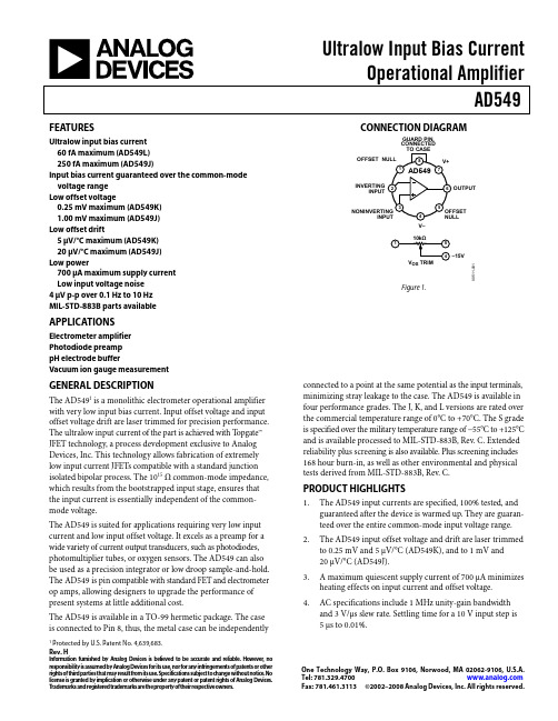
FEATURES
Ultralow input bias current 60 fA maximum (AD549L) 250 fA maximum (AD549J)
Input bias current guaranteed over the common-mode voltage range
Ultralow Input Bias Current Operational Amplifier AD549
CONNECTION DIAGRAM
GUARD PIN, CONNECTED
TO CASE
OFFSET NULL
8
V+
1 AD549 7
INVERTING INPUT
2
6 OUTPUT
3 NONINVERTING
4. AC specifications include 1 MHz unity-gain bandwidth and 3 V/μs slew rate. Settling time for a 10 V input step is 5 μs to 0.01%.
One Technology Way, P.O. Box 9106, Norwood, MA 02062-9106, U.S.A.
Tel: 781.329.4700
Fax: 781.461.3113 ©2002–2008 Analog Devices, Inc. All rights reserved.
元器件交易网
AD549
TABLE OF CONTENTS
Features .............................................................................................. 1 Applications....................................................................................... 1 Connection Diagram ....................................................................... 1 General Description ......................................................................... 1 Product Highlights ........................................................................... 1 Revision History ............................................................................... 2 Specifications..................................................................................... 3 Absolute Maximum Ratings............................................................ 5
Agilent54600系列用户指南(中文).
用户指南出版号 54622-970322002 年 3 月有关安全保修和规章信息请参见索引后面的部分©Copyright Agilent Technologies 2000-2002All Rights ReservedAgilent 54621A/22A/24A/41A/42A 示波器和Agilent 54621D/22D/41D/42D 混合信号示波器ii示波器总览选择一个示波器来捕获长的非重复信号每通道 200MSa/s 取样率 , 2MBytes MegaZoom 深存储器• Agilent 54621A - 2通道 60MHz 带宽• Agilent 54621D - 2 通道 +16 个逻辑通道 60MHz 带宽• Agilent 54622A - 2 通道 , 100MHz 带宽• Agilent 54622D - 2 通道 +16 个逻辑通道 100MHz 带宽• Agilent 54624A - 4通道 100MHz 带宽每通道 2GSa/s取样率 4MBytes MegaZoom 深存储器• Ag ilent 54641A - 2通道 350MHz 带宽• Agilent 54641D - 2 通道 + 16个逻辑通道 350MHz 带宽• Agilent 54642A - 2通道 500MHz 带宽• Agilent 54642D - 2 通道 + 16个逻辑通道 500MHz 带宽在屏幕上显示当前输入信号• 显示主要工作模式和延迟工作方式下的所有模拟和数字(54621D/22D/41D/42D 通道•通道时基数字 (54621D/22D/41D/42D 通道活动状态触发和采集状态指示器• 软键标签• 测量结果数字通道控制选择位置和标签输入 (54621D/22D/41D/42D• 独立接通或关闭通道或以 8 个为一组接通或关闭• 重新排列通道顺序以将相关信号分组• 创建并显示标签以标识通道Run 控制键可以开始和结束数据采集• Run/Stop 开始和停止连续采集• Single 执行单次采集• 无限余辉累积并显示多次采集的结果一般控制测量保存和恢复结果并配置示波器• 波形数学函数包括FFT减法乘法积分和微分• 使用 Quick Meas 进行自动测量 Quick Meas 中包含集成计数器• 使用游标进行手动测量• 保存或调用测量配置或以前的测量结果• Autoscale 执行简单的单按钮示波器设置水平控制选择扫描速度和延迟参数•扫描速率为 5ns/div 到 50ns/div54620系列和 1ns/div 到50s/div54640 系列• 延迟控制将波形移动到感兴趣的点•延迟方式和延迟允许放大以显示波形某一部分的细节拆分屏幕 Trigger 键定义示波器在何种数据上触发• Source 键允许传统示波器触发• 工作方式包括边沿脉冲宽度码型 CAN 持续时间 I 2C序列SPI TV 和 USB触发软键扩展了命令键的功能选择测量类型工作方式触发技术规范标签数据等利用灵活的探测系统进行数字通道输入(54621D/22D/41D/42D• 16 个通道经带有微型线夹的双 8 通道电缆输入信号• 将逻辑电平设置为TTLCMOS ECL 或用户定义的电压实用程序• 专用并行打印机端口控制器操作软盘存储内置快速帮助系统• 按住任意前面板键或软键以获取 11 种语言的帮助iii本书内容本手册为您使用示波器提供指导包括以下章节第 1 章入门检查清洁和设置示波器和使用快速帮助第 2 章前面板纵览帮助您熟悉前面板操作的快速入门指南第 3 章触发示波器使用各种工作方式触发示波器的方法第 4 章 MegaZoom 概念和示波器操作采集波形水平和垂直操作使用数字通道第 5 章进行测量捕获数据使用数学函数使用游标和自动测量进行测量第 6 章实用程序配置 I/O打印设置快速帮助软盘操作用户校准和自校准设置时钟和屏幕保护第 7 章性能特性iv目录1入门设置示波器 1-4检查包装箱内装物品 1-5检查选件和附件 1-8对示波器进行清洁处理 1-11调整手柄 1-12接通示波器电源 1-13调整波形亮度 1-14连接示波器模拟探头 1-15补偿模拟探头 1-16使用数字探头仅限于混合信号示波器 1-17连接打印机 1-21连接 RS-232 电缆 1-21检查示波器的基本工作状况 1-22从使用示波器界面开始 1-23使用快速帮助 1-25在示波器启动时选择快速帮助的语言 1-25在开始使用示波器后选择快速帮助的语言 1-26 从软盘装入更新语言文件 1-262前面板纵览示波器使用注意事项 2-354620/40 系列示波器的前面板 2-6前面板操作 2-9显示信息的说明 2-10用模拟通道查看信号 2-11用数字通道查看信号 2-12用 Autoscale 自动显示信号 2-13应用默认工厂配置 2-14调整模拟通道垂直定标和位置 2-15设置模拟信号垂直扩展参考 2-16设置模拟通道的探头衰减系数 2-16显示和重新排列数字通道 2-17操作时基控制 2-18开始和停止采集 2-19进行单次采集 2-19使用延迟扫描 2-20进行游标测量 2-21进行自动测量 2-22目录 -1目录目录 - 2调节显示网格 2-23打印显示 2-233触发示波器选择触发模式和触发条件 3-3选择模式和耦合菜单 3-3选择触发模式NormalAutoAuto Level 3-4选择触发耦合 3-6选择噪声抑制和高频抑制 3-6设置释抑 3-7外部触发输入 3-9触发类型 3-11 使用边沿触发 3-12使用脉冲宽度触发 3-14使用码型触发 3-17使用 CAN 触发 3-19使用持续时间触发 3-21使用 I2C 触发 3-24使用序列触发 3-28使用 SPI 触发 3-34使用TV电视触发 3-38使用 USB 触发 3-48触发输出连接器 3-504MegaZoom 概念和示波器操作MegaZoom 概念 4-3深存储器 4-4示波器响应 4-5显示屏更新率 4-6设置模拟通道 4-7设置水平时基 4-10采集模式 4-15显示模式 4-19平移和缩放 4-21平移和缩放波形 4-22运行 /停止 /单次 /无限余辉操作 4-23 采集数据 4-24存储器深度 /记录长度 4-25目录目录 -3运行和停止采集 4-26获取单条轨迹 4-26捕获单个事件 4-27使用无限余辉 4-28用无限余辉存储多个重复事件 4-28 清除波形显示 4-29配置混合信号示波器 4-30用 Autoscale 显示数字通道 4-30解释数字波形显示 4-31显示和重新排列数字通道 4-32开启和关闭单个通道 4-33强制开启或关闭所有通道 4-34更改数字通道显示的大小 4-34更改数字通道的逻辑门限 4-35用数字通道检测电路 4-36在混合信号示波器上使用标签 4-40 开启或关闭标签显示 4-41为通道分配预定义标签 4-42定义新标签 4-43复位标签库至工厂默认设置 4-45保存和调用轨迹及设置 4-46自动保存轨迹和设置 4-47把轨迹和设置保存到内部存储器或覆盖现有软盘文件 4-48 把轨迹和设置保存到软盘上的新文件 4-49调用轨迹和设置 4-50保存打印屏幕图像至软盘 4-51调用工厂默认设置 4-525进行测量捕获数据 5-3使用延迟扫描 5-4减小信号上的随机噪声 5-6用峰值检测和无限余辉捕获毛刺和窄尖峰 5-10使用滚动水平模式 5-11使用 XY 水平模式 5-12数学函数 5-16数学定标和偏置 5-17乘法 5-18目录减法 5-19微分 5-20积分 5-22FFT 测量 5-24游标测量 5-30进行游标测量 5-31自动测量 5-36进行自动测量 5-37进行自动时间测量 5-38进行延迟和相位测量 5-41进行自动电压测量 5-43进行过冲和前冲测量 5-466实用程序配置快速帮助语言 6-3将仪器更新到最新的应用程序软件 6-5配置打印机 6-6 使用软盘 6-8为使用控制器而设置 I/O 端口 6-9设置时钟 6-11设置屏幕保护 6-12执行维护功能 6-14设置其他选项 6-167性能特性Agilent 54620 系列性能特性 7-3 Agilent 54640 系列性能特性 7-13目录 - 41入门1-2入门使用示波器进行系统测试或故障检修时需要进行以下操作• 连接示波器电源按使用要求调节仪器手柄和屏幕亮度•通过理解要测试的系统参数及预期的系统行为来定义测量问题•把探头接到被测电路中适当的信号点和接地点来设置通道输入•定义在有关特定事件波形数据的触发• 使用示波器以连续或单次方式采集数据• 用各种功能检查数据并进行测量• 保存测量结果或配置状态以供日后再次使用或与其他测量相比较如有必要可重复上述过程直到您确认示波器已正常工作或找到了问题的原因MegaZoom 技术使用未经触发的数据工作把 MegaZoom技术置入示波器后就可以用未经触发的数据操作示波器在自动触发模式下只需按下Run运行或Single单次按钮然后检验数据即可设置触发1-3入门示波器的高速显示可用于隔离很少发生变化的信号然后用这些信号特性精确确定触发参数有关触发数据采集数据检查数据测量和配置的详细内容请参见以下各章使用示波器精确确定触发条件准备使用示波器定义简单触发和重新采集数据检查显示精确确定触发定义测量问题保存配置以备以后使用设置探头检查和测量数据采集数据定义触发条件否是显示是否符合要求1-4设置示波器使用示波器之前需要做以下准备工作完成后您就可随时使用示波器在下面各节中您将• 检查包装箱内装物品• 检查选件和附件• 了解如何对示波器作清洁处理• 调整手柄• 接通示波器电源• 调整显示亮度• 连接示波器探头•连接数字探头54621D/22D/41D/42D• 连接打印机• 连接 RS-232 电缆• 检查示波器的基本工作状况• 从使用示波器界面开始• 了解如何使用快速帮助1-5入门检查包装箱内装物品检查包装箱内装物品❏检查装运包装箱是否损坏如果发现包装箱破损请保存好包装箱及填充材料直至完成设备完整性检查和示波器的机械和电气性能检查❏请确认示波器包装箱内包括以下物品及可选附件见下图• 54620/40系列示波器54621A21D22A 22D 24A41A41D 42A 或42D• 带 ID 的 10:1无源探头(2 10074C (150MHz用于54621A21D 22A 或 22D(4 10074C (150MHz用于 54624A (2 10073C (500MHz用于54641A41D 42A 或 42D• 54620-68701数字探头套件用于54621D 22D 41D 或42D•附件袋和前面板罩是 54621A 和 21D 以外的示波器的标准配置对于 54621A 和 21D 订购号为N2726A•电源线参见表 1-3• 用于 54600 系列示波器的 IntuiLink 软件和 RS-232电缆适用于 54621A 和 21D以外的所有示波器IntuiLink 是一个 Windows 应用程序可使您使用 Microsoft Word 或 Microsoft Excel轻松地将图片波形数据或示波器设置从示波器下载到您的 PC 机上安装了IntuiLink 之后在这些 Microsoft 应用程序中有一个工具栏可使您能够很简单地连接示波器或从示波器传输数据54621A 和 21D 用户可从下列网站得到免费的用于 54600 系列示波器的IntuiLink软件/find/5462xswRS-232电缆可单独订购产品编号为 34398A1-6入门检查包装箱内装物品•Agilent IntuiLink Data Capture 适用于 54621A 和 21D 以外的所有示波器IntuiLink Data Capture 是一个独立程序用于通过 GPIB 或 RS-232 接口将波形数据从示波器下载到您的PC它提供从示波器输出高达4MB示波器通道和 8MB逻辑通道的深存储器数据的功能不管屏幕上的实际采集点数是多少用于 54600 系列的 IntuiLink可以将可用的采集数据大小限制在最大 2000 点之内使用 IntuiLink Data Capture传输的点数为当前显示的实际采集点数或者您可以选择要下载的点数该软件提供下列功能•下载波形数据并用简单图表显示该数据• 将数据保存为二进制或文本文件• 将图表和选定的部分数据复制到剪贴板可保存到剪贴板的最大数据为50000 点• 将已保存的波形数据装回应用程序54621A 和 21D 用户可从下列网站获取免费的 IntuiLink Data Capture 软件/find/5462xswRS-232电缆可单独订购产品编号为 34398A如有缺失请与最近的安捷伦科技公司销售部门联系如果包装箱破损请先与承运商联系然后通知最近的安捷伦公司销售部门❏检查示波器•如果示波器有机械损伤或缺陷不能正常工作或未通过Service Guide维修指南中所述的性能测试请通知安捷伦公司的销售部门• 如果装运包装箱损坏或填充材料有受过挤压的痕迹请通知承运商和安捷伦公司的销售部门请保存好包装材料以供承运商检验安捷伦公司的销售部门将自行选择修理或更换仪器而不必等待索赔结果1-7入门检查包装箱内装物品54620/40 系列示波器包装箱内装物品10073C 或 10074C 探头电源线附件袋和前面板罩 **54620-61801 16 通道电缆5959-9334 2in. 接地线 5 条5090-4356 探钩 20 个用于 54600 系列的 IntuiLink 软件 Data Capture 软件或串行电缆 **54620/40 系列示波器 54620-68701 数字探头套件 ** 仅限 54621D/22D/41D/42D ** 除 54621A/21D 外的所有示波器1-8入门检查选件和附件检查选件和附件❏确认您已收到所有订购的选件和附件并且没有损坏如有缺失请与最近的安捷伦科技公司销售部门联系如果包装箱损坏或填充材料有受过挤压的痕迹请通知承运商和安捷伦科技公司销售部门表 1-1 和 1-2 列出部分适用于 54620/40系列示波器的选件和附件要了解所有可使用的选件和附件请与安捷伦科技公司的销售部门联系表 1-1可提供的选件选件说明003屏蔽选件用于恶劣环境或在测量敏感器件时使用–双向屏蔽输入和输出添加到 CRT 的 RS-03 磁接口屏蔽添加到 CRT 的 RE-02 显示屏蔽用于降低辐射干扰 1CM 机架安装套件与1186A 相同A6J ANSII Z540 鉴定校准带测试数据W323 年客户返回的校准服务 W343 年客户返回的标准鉴定校准服务W50附加的 2 年保修共 5 年W525 年客户返回的校准服务 W545 年客户返回的标准鉴定校准服务有关电源线选件的说明参见表 1-31-9入门检查选件和附件表 1-2可提供的附件型号说明 1146A 电流探头 AC/DC1183A 示波器测试车1185A 仪器箱 1186A 机架安装套件 10070C 带 ID 的 1:1 无源探头 10072A 小节距探头套件 10075A 0.5mm IC 探钩套件 10076A 带 ID 的100:14kV250MHz 探头10085A 16:16 逻辑电缆和端接器用于54621D/22D/41D/42D10089A 16:2 x 8 逻辑输入探头组件为 54621D/22D/41D/42D 的标准配置随机提供10100C 50Ω 端接10833A GPIB 电缆长度为 1m 34398A RS-232电缆除 54621A/21D外的标准配置E2613B 0.5mm 楔形探头适配器 3 信号 2 个 E2614A 0.5mm 楔形探头适配器 8 信号 1 个 E2615B 0.65mm 楔形探头适配器 3信号 2 个 E2616A 0.65mm 楔形探头适配器 8信号 1 个 E2643A 0.5mm楔形探头适配器 16 信号 1 个 E2644A 0.65mm 楔形探头适配器 16信号1 个N2726A 附件袋和前面板罩除 54621A/21D外均为标准配置N2727A 热敏打印机和仪器袋 N2728A 10 卷热敏打印纸 N2757A GPIB 接口模块 N2772A 20MHz 差分探头 N2773A 差分探头电源 N2774A 50MHz 电流探头AC/DCN2775AN2774A 的电源入门检查选件和附件表 1-3电源线插头类型电缆产品编号插头类型电缆产品编号选件 900英国 8120-1703选件918日本 8120-4754选件 901澳大利亚 8120-0696选件 919以色列 8120-6799选件 902欧洲 8120-1692选件 920阿根廷 8120-6871选件 903美国 8120-1521选件 921智利 8120-6979选件 906瑞士 8120-2296选件 922中国 8120-8377选件 912丹麦 8120-2957选件 927泰国 8120-8871选件 917非洲 8120-46001-101-11入门对示波器进行清洁处理对示波器进行清洁处理1拔掉仪器的电源线小心对示波器进行清洁处理时不要使用过多的液体水可能会渗入前面板键盘控制旋钮和软盘中从而损坏敏感的电子元件2用蘸有中性皂液的软布擦拭示波器3在再次连接示波器电源前要保证仪器已完全干燥1-12入门调整手柄调整手柄1握住仪器两侧手柄的转轴处将转轴向外拉直至拉不动为止2不要松开转轴把手柄转到所需位置松开转轴继续转动手柄直到手柄咔嗒一声锁定到位1-13入门接通示波器电源接通示波器电源1另一端接到适合的交流电源示波器电源能在 100 - 240VAC 电源电压范围内自动调整因此无需调整输入电源电压设置提供的电源线符合所在国的标准为确保使用了正确的电源线请参见表 1-3一些前面板键指示灯将变亮大约 5 秒后示波器可以工作入门调整波形亮度调整波形亮度••图 1-1亮度控制旋钮可按 Display 显示键然后旋转输入旋钮在前面板标有以调整 Grid 网格控制1-141-15入门连接示波器模拟探头连接示波器模拟探头这些示波器的模拟输入阻抗可以选择 50Ω只适用于 54640系列或 1MΩ50Ω 模式与通常用于高频测量的50Ω 电缆相匹配此阻抗匹配为您提供最精确的测量因为此时沿信号路径的反射最小1M Ω 模式用于探头和通用测量较高的阻抗可将示波器对被测试电路的负载效应最小化小心在 54640 系列的50Ω 模式中切勿超过5Vrms 50Ω 模式启用了输入保护如果检测到超过 5Vrms 的电压将会断开50Ω 负载然而输入仍有可能被损坏这与信号的时间常数有关小心 54640系列的50Ω 输入保护模式只有在示波器通电的情况下才发挥作用1把提供的 1.5m10:1 示波器探头接到示波器模拟通道的BNC 连接器输入模拟输入的最高输入电压I 类 300Vrms, 400VpkII 类 100Vrms, 400Vpk带 10073C 或 10074C 10:1 探头 I 类500Vpk, II 类 400Vpk2把探头上的收缩式探钩接到有关的电路点要保证把探头接地线连到电路接地点探头接地线被接到示波器底盘和电源线中的地线如果需要把接地线连到不能用电源线接地的电路中的某一点就应考虑使用差分探头1-16入门补偿模拟探头补偿模拟探头您应对模拟探头进行补偿以使其特性与示波器相匹配补偿不好的探头可能导致测量误差要补偿探头请执行下列操作 1将探头从通道 1 连接到前面板右下角的Probe Comp探头补偿信号 2按下Autoscale自动定标 3使用一个非金属工具调整探头上的微调电容器以获取最平坦脉冲完美补偿过补偿补偿不足1-17入门使用数字探头仅限于混合信号示波器使用数字探头仅限于混合信号示波器1如有必要可切断被测电路的电源切断被测电路电源只是为了防止在连接探头时因不小心把两条线短路而造成电路损坏由于探头上没有电压因此可将示波器电源保持接通状态 2把数字探头电缆接到混合信号示波器前面板的D15 - D0连接器数字探头电缆带有标识因此您只能以一个方向连接在连接电缆时不安捷伦产品编号为 54620 - 68701 的数字探 10089A 的附加探头套件1-18入门使用数字探头仅限于混合信号示波器3把探钩连到一条探头线上要确保连接地线为清楚起见图中省略了其他探头线 4把探钩接到您要测试的电路结点探钩1-19入门使用数字探头仅限于混合信号示波器并把探 61-20入门使用数字探头仅限于混合信号示波器7重复步骤 3 至 6直至完成对所有有关的点的连接8如果您要从电缆中取出探头线可将回形针或其他小型针状物件插入电缆组件的一侧按下以松开弹片并拔出探头线可提供替换部件有关详细内容请参见Service Guide维修指南的Replaceable Parts可替换部件一章1-21入门连接打印机连接打印机示波器通过后面板上的并行输出连接器与打印机相连连接打印机需要一条并行打印机电缆 1把 25针小 D型连接器接到示波器后面板上的并行输出连接器拧紧电缆连接器上的指旋螺钉以保证电缆的可靠连接2把 36针大 D 型连接器接到打印机上3在示波器上设置打印机配置a 按Utility 实用程序键然后按Print Confg打印配置软键 b 按Print to:打印至软键将接口设置为 Parallel并行c 按Format格式软键从列表中选择打印机格式有关打印机配置的详细内容请参见实用程序一章连接 RS-232 电缆示波器可通过后面板上的 RS-232 连接器接到控制器或 PC所有示波器除了 54621A/21D均提供 RS-232 电缆对于 54621A/21D 示波器可作为选件订购该电缆1把 RS-232 电缆上的 9 针 D 型连接器接到示波器后面板上的 RS-232连接器拧紧电缆连接器上的指旋螺钉以保证电缆的可靠连接 2把电缆另一端接到控制器或 PC3在示波器上设置 RS-232 配置a 按 Utility 键然后按I/O输入输出软键b 按Controller控制器软键并选择 RS-232 c 按Baud波特率软键设置与控制器或 PC相符的波特率d 按 XON DTR 软键设置与控制器或 PC相符的信号交换有关 RS-232配置的详细内容请参见实用程序一章1-22入门检查示波器的基本工作状况检查示波器的基本工作状况1把示波器探头接到通道12把探头接到示波器前面板右下方的 Probe Comp输出使用探头的收缩式探钩您就不必总握住探头3按前面板上的Save/Recall保存调用键然后按显示器下面的Default Setup默认设置软键现在已把示波器配置为默认设置 4按前面板上的 Autoscale键现在应看到峰 -峰幅度大约 5 格周期大约 4 格的方波如下图所示如果未能看到该波形。
CS5460A中文数据手册
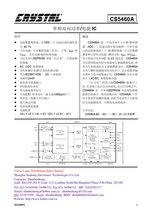
l 片内功能:可以测量电能(有功),I *V,IRMS 和 VRMS ,具有电能-脉冲转换功能
l 可以从串行EEPROM 智能“自引导”,不需要微 控制器
l AC 或DC 系统校准 l 具有机械计度器/步进电机驱动器 l 符合IEC687/1036 ,JIS 工业标准 l 功耗<12mW l 优化的分流器接口 l V对I的相位补偿 l 单电源地参考信号 l 片内2.5V 参考电压(最大温漂60ppm/℃) l 简单的三线数字串行接口 l 看门狗定时器 l 内带电源监视器 l 电源配置
VA+ = +5 V; VA- = 0V; VD+ = +3.3V~+5 V
概述
CS5460A 是一个包含两个ΔΣ模-数转换 器(ADC)、高速电能计算功能和一个串行接 口的高度集成的ΔΣ 模-数转换器。它可以精确 测量和计算有功电能、瞬时功率、IRMS 和VRMS , 用于研制开发单相2 线或3 线电表。CS5460A 可以使用低成本的分流器或互感器测量电流,使 用分压电阻或电压互感器测量电压。CS5460A 具有与微控制器通讯的双向串口,芯片的脉冲输 出频率与有功能量成正比。CS5460A 具有方便 的片上AC/DC 系统校准功能。
cs5460a单相双向功率电能ic特性rms具有电能脉冲转换功能可以从串行eeprom智能自引导不需要微控制器ac或dc系统校准符合iec6871036jis工业标准片内25v参考电压最大温漂60ppm电源配置va0v
AD548中文资料

1. A combination of low supply current, excellent dc and ac performance and low drift makes the AD548 the ideal op amp for high performance, low power applications. 2. The AD548 is pin compatible with industry standard op amps such as the LF441, TL061, and AD542, enabling designers to improve performance while achieving a reduction in power dissipation of up to 85%. 3. Guaranteed low input offset voltage (2 mV max) and drift (20 µV/°C max) for the AD548J are achieved utilizing Analog Devices’ laser drift trimming technology, eliminating the need for external trimming. 4. Analog Devices specifies each device in the warmed-up condition, insuring that the device will meet its published specifications in actual use. 5. A dual version, the AD648 is also available. 6. Enhanced replacement for LF441 and TL061.
2N5460资料

9
–1
–5
–2
–9
–4 –16 mA
0.003
5
5
5
nA
0.0003
1
1
1
mA
3 pA
–5
1.3
0.5
4
2.3
0.8 4.5
3.8
1.5
6
V
–0.7
Dynamic
Common-Source Forward Transconductance
Common-Source Output Conductance
元器件交易网
P-Channel JFETs
2N/SST5460 Series
Vishay Siliconix
2N5460 2N5461 2N5462
SST5460 SST5461 SST5462
PRODUCT SUMMARY
Part Number
2N/SST5460 2N/SST5461 2N/SST5462
元器件交易网
2N/SST5460 Series
Vishay Siliconix
TYPICAL CHARACTERISTICS (TA = 25_C UNLESS OTHERWISE NOTED)
Transfer Characteristics –5
VGS(off) = 1.5 V
1000
100
rDS(on) – Drain-Source On-Resistance ( Ω )
IDSS – Saturation Drain Current (mA)
gos– Output Conductance ( mS) gfs – Forward Transconductance (mS)
BS-546 中文版
不适用。
第六部分:标记
30. 插头、插座和插座转换器应清晰耐久地标有以下信息,且这些标记不能置于螺钉、可 动垫圈或其他可动部件上,也不能置于可单独出售的零件上。
制造商或责任经销商的名称或商标。 英国标准号,也即 BS 。 546* 此外,这些产品还需标有以下内容: 插头. a. 连接相线与中线的端子须有相应的标识 L 和 N。保护接地端子标识应为 (推荐) 或者 并附有字母 。【 】 E AMD8914 b. 带熔断器插头。文字“FUSED”,且应在插头与插座插合时可见。 c. 带熔断器插头。文字“USE CORRECT FUSE-LINKS”,或者同义词。 插座 【 】 . AMD8914 a. 额定电流; b. 额定电压,如 ; 250V c. 电源性质,如~(推荐)或 a.c.
所有材料应符合相关 BS 标准.由铁金属制成的部件应能防锈,对弹簧及移动部件应特别注 意。
以下材料应用于表 5 所述零部件中。
a. 韧性 当据 BS 2782 第 1 部分 方法 102A 的塑变值试验在 100℃进行试验时,其塑变值
不超过 6mm 的阻燃绝缘材料。
b. 强度 当据 BS 2782 第 1 部分 方法 102A 的塑变值试验在 100℃进行试验时,其塑变值
插座转换器的额定电流见条款 。29 意外接触的预防
7. 除了邻近插头或插座转换器安装板的载流插销的外露部分可使用套管绝缘外 (套管的最 小长度见表 1) , 任何部件与插头或插座适配器安装板的外围距离不得小于表 1 所给出的 最小距离值。
表 1 长度与距离
Current rating
Minimum length
除了 30A 插座插套的端子只需一根导线外,每个端子都应提供合适的方式来与最多两 根导线进行牢固连接。
AD548JN中文资料
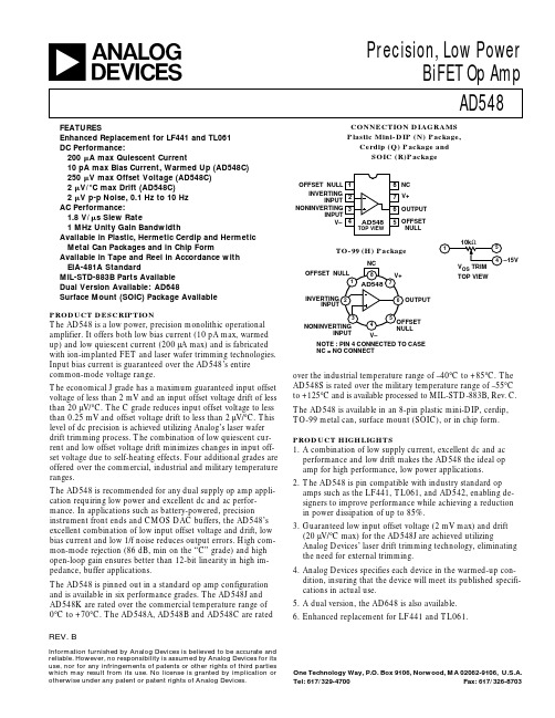
8 NC 7 V+ 6 OUTOFFSET NULL 10kΩ
5 4
TO-99 (H) Package
NC OFFSET NULL
1 8
1
–15V
VOS TRIM V+
7 6
TOP VIEW
AD548
INVERTING 2 INPUT
3 5 4
OUTPUT
The AD548 is a low power, precision monolithic operational amplifier. It offers both low bias current (10 pA max, warmed up) and low quiescent current (200 µA max) and is fabricated with ion-implanted FET and laser wafer trimming technologies. Input bias current is guaranteed over the AD548’s entire common-mode voltage range. The economical J grade has a maximum guaranteed input offset voltage of less than 2 mV and an input offset voltage drift of less than 20 µV/°C. The C grade reduces input offset voltage to less than 0.25 mV and offset voltage drift to less than 2 µV/°C. This level of dc precision is achieved utilizing Analog’s laser wafer drift trimming process. The combination of low quiescent current and low offset voltage drift minimizes changes in input offset voltage due to self-heating effects. Four additional grades are offered over the commercial, industrial and military temperature ranges. The AD548 is recommended for any dual supply op amp application requiring low power and excellent dc and ac performance. In applications such as battery-powered, precision instrument front ends and CMOS DAC buffers, the AD548’s excellent combination of low input offset voltage and drift, low bias current and low 1/f noise reduces output errors. High common-mode rejection (86 dB, min on the “C” grade) and high open-loop gain ensures better than 12-bit linearity in high impedance, buffer applications. The AD548 is pinned out in a standard op amp configuration and is available in six performance grades. The AD548J and AD548K are rated over the commercial temperature range of 0°C to +70°C. The AD548A, AD548B and AD548C are rated REV. B
常用AD芯片介绍共7页word资料

目前生产AD/DA的主要厂家有ADI、TI、BB、PHILIP、MOTOROLA等,武汉力源公司拥有多年从事电子产品的经验和雄厚的技术力量支持,已取得排名世界前列的模拟IC生产厂家ADI、TI 公司代理权,经营全系列适用各种领域/场合的AD/DA器件。
1. AD公司AD/DA器件AD公司生产的各种模数转换器(ADC)和数模转换器(DAC)(统称数据转换器)一直保持市场领导地位,包括高速、高精度数据转换器和目前流行的微转换器系统(MicroConvertersTM )。
1)带信号调理、1mW功耗、双通道16位AD转换器:AD7705AD7705是AD公司出品的适用于低频测量仪器的AD转换器。
它能将从传感器接收到的很弱的输入信号直接转换成串行数字信号输出,而无需外部仪表放大器。
采用Σ-Δ的ADC,实现16位无误码的良好性能,片内可编程放大器可设置输入信号增益。
通过片内控制寄存器调整内部数字滤波器的关闭时间和更新速率,可设置数字滤波器的第一个凹口。
在+3V电源和1MHz主时钟时, AD7705功耗仅是1mW。
AD7705是基于微控制器(MCU)、数字信号处理器(DSP)系统的理想电路,能够进一步节省成本、缩小体积、减小系统的复杂性。
应用于微处理器(MCU)、数字信号处理(DSP)系统,手持式仪器,分布式数据采集系统。
2)3V/5V CMOS信号调节AD转换器:AD7714AD7714是一个完整的用于低频测量应用场合的模拟前端,用于直接从传感器接收小信号并输出串行数字量。
它使用Σ-Δ转换技术实现高达24位精度的代码而不会丢失。
输入信号加至位于模拟调制器前端的专用可编程增益放大器。
调制器的输出经片内数字滤波器进行处理。
数字滤波器的第一次陷波通过片内控制寄存器来编程,此寄存器可以调节滤波的截止时间和建立时间。
AD7714有3个差分模拟输入(也可以是5个伪差分模拟输入)和一个差分基准输入。
单电源工作(+3V或+5V)。
brother MFC-5460CN 使用说明书

3 常规设置
18
节电模式 ............................................................. 18 使您的设备进入节电模式 ........................................... 18 使您的设备退出节电模式 ........................................... 18 节电模式设置 ..................................................... 18
i
第 II 部分 传真
5 发送传真
24
进入传真模式 ......................................................... 24 从自动进稿器发送传真.............................................. 24 从平板扫描器上发送传真............................................ 24 从平板扫描器传真 Letter 尺寸的原稿................................. 25 彩色传真传输...................................................... 25 取消正在处理的传真................................................ 25
操作面板概述 .......................................................... 5
2 装入原稿和纸张
7
装入原稿 .............................................................. 7 使用自动进稿器 .................................................... 7 使用平板扫描器 .................................................... 8 扫描区域 .......................................................... 9
美菱546法式冰箱的说明书
美菱546法式冰箱的说明书摘要:1.美菱546 法式冰箱的特点2.美菱546 法式冰箱的功能3.美菱546 法式冰箱的使用方法4.美菱546 法式冰箱的维护保养正文:美菱546 法式冰箱是一款具有高性能、高效率和环保特性的冰箱,它不仅拥有精美的外观,还具有许多实用的功能。
下面,我们将详细介绍这款冰箱的特点、功能、使用方法以及维护保养方法。
首先,让我们来了解一下美菱546 法式冰箱的特点。
这款冰箱采用法式设计,外观时尚、简约,适合现代家庭使用。
其主要特点是大容量、多隔层,能够满足用户对于储存空间的需求。
此外,美菱546 法式冰箱还采用了智能温控系统,能够保证食物新鲜度,为用户提供更好的使用体验。
接下来,我们来了解一下美菱546 法式冰箱的功能。
这款冰箱具有低温凝湿技术,能够有效防止霜冻,保证食物新鲜。
此外,它还具有静音运行功能,让您在使用过程中免受噪音困扰。
美菱546 法式冰箱还配备了节能功能,能够有效降低能耗,既环保又省钱。
在了解了美菱546 法式冰箱的特点和功能之后,我们来学习一下如何使用这款冰箱。
首先,将冰箱插头插入电源插座,然后打开冰箱门,检查各个隔层是否安装正确。
接下来,您可以开始将食物放入冰箱。
在使用过程中,请注意保持冰箱内部整洁,以保证食物新鲜度。
此外,还要定期对冰箱进行清洁和消毒,以保证冰箱的使用寿命。
最后,我们来介绍一下美菱546 法式冰箱的维护保养方法。
首先,要定期检查冰箱的电源线是否完好,避免因电源线损坏导致冰箱无法正常工作。
其次,要定期清洁冰箱内部,可以使用湿布擦拭,但要避免使用有腐蚀性的清洁剂。
最后,要注意冰箱的摆放位置,避免阳光直射和潮湿环境,以保证冰箱的正常使用。
总之,美菱546 法式冰箱是一款性能优越、外观时尚的冰箱,它具有许多实用的功能,能够满足用户对于冰箱的需求。
在使用过程中,要注意维护保养,以延长冰箱的使用寿命。
AD数据手册部分内容中文翻译
AD9959数据手册(部分)GENERAL DESCRIPTION概述The AD9959 consists of four direct digital synthesizer (DDS) cores that provide independent frequency, phase, and amplitude control on each channel. This flexibility can be used to correct imbalances between signals due to analog processing, such as filtering, amplification, or PCB layout-related mismatches. Because all channels share a common system clock, they are inherently synchronized. Synchronization of multiple devices is supported. The AD9959 can perform up to a 16-level modulation of frequency, phase, or amplitude (FSK, PSK, ASK). Modulation is performed by applying data to the profile pins. In addition, the AD9959 also supports linear sweep of frequency, phase, or amplitude for applications such as radar and instrumentation.AD9959含有四个直接数字频率合成器(DDS),提供各通道独立的频率、相位和振幅控制。
Agilent 54620A C 复杂版型式数字波形捕捉设备说明书
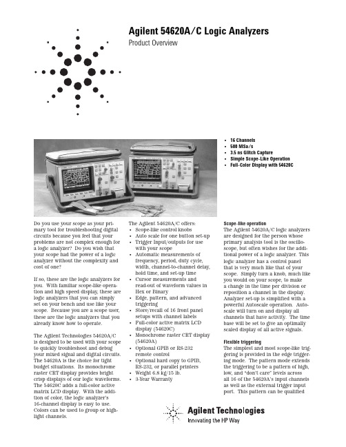
Do you use your scope as your pri-mary tool for troubleshooting digital circuits because you feel that your problems are not complex enough for a logic analyzer? Do you wish that your scope had the power of a logic analyzer without the complexity and cost of one?If so, these are the logic analyzers for you. With familiar scope-like opera-tion and high speed display, these are logic analyzers that you can simply set on your bench and use like your scope. Because you are a scope user, these are the logic analyzers that you already know how to operate.The Agilent Technologies 54620A/C is designed to be used with your scope to quickly troubleshoot and debug your mixed signal and digital circuits. The 54620A is the choice for tight budget situations. Its monochrome raster CRT display provides bright crisp displays of our logic waveforms. The 54620C adds a full-color active matrix LCD display. With the addi-tion of color, the logic analyzer’s16-channel display is easy to use. Colors can be used to group or high-light channels.The Agilent 54620A/C offers:• Scope-like control knobs• Auto scale for one button set-up• Trigger Input/outputs for usewith your scope• Automatic measurements offrequency, period, duty cycle,width, channel-to-channel delay,hold time, and set-up time• Cursor measurements andread-out of waveform values inHex or Binary• Edge, pattern, and advancedtriggering• Store/recall of 16 front panelsetups with channel labels• Full-color active matrix LCDdisplay (54620C)• Monochrome raster CRT display(54620A)• Optional GPIB or RS-232remote control• Optional hard copy to GPIB,RS-232, or parallel printers• Weight 6.8 kg/15 lb.• 3-Year WarrantyScope-like operationThe Agilent 54620A/C logic analyzersare designed for the person whoseprimary analysis tool is the oscillo-scope, but often wishes for the addi-tional power of a logic analyzer. Thislogic analyzer has a control panelthat is very much like that of yourscope. Simply turn a knob, much likeyou would on your scope, to makea change in the time per division orreposition a channel in the display.Analyzer set-up is simplified with apowerful Autoscale operation. Auto-scale will turn on and display allchannels that have activity. The timebase will be set to give an optimallyscaled display of all active signals.Flexible triggeringThe simplest and most scope-like trig-gering is provided in the edge trigger-ing mode. The pattern mode extendsthe triggering to be a pattern of high,low, and “don’t care”levels acrossall 16 of the 54620A’s input channelsas well as the external trigger inputport. This pattern can be qualified Agilent 54620A/C Logic AnalyzersProduct Overview•16 Channels•500 MSa/s• 3.5 ns Glitch Capture•Simple Scope-Like Operation•Full-Color Display with 54620Cwith an edge. For those applications where more triggering power is needed to isolate the event of interest, the Advanced trigger mode is available. High speed displayAn important consideration of a troubleshooting tool is its abilityto clearly display changes in the circuit under test. The 54620A/C employs an advanced four processor architecture, giving you a logic ana-lyzer that can display changing wave-forms in your system that would be missed by more traditional analyzers. Another benefit of the high speed display system is that the 54620A/C will respond instantly to your front panel control inputs. This eliminates a source of confusion in your trou-bleshooting process.See more with colorThe display of 16 logic channels can be somewhat confusing. By the use of color, you can group channels that are displaying related information, or specific channels can be highlighted. For example, address lines can bein one color while control lines are displayed in other colors. Alternate palettes allow the display to be cus-tomized for most favorable viewing. Upgrade to meet your changing needs You can upgrade the Agilent 54620A logic analyzer to produce hard copies to either printer or plotter Or, you can interface it to a computer with either GPIB or RS-232 interfaces. Using the HP 34810B BenchLink Scope for Windows, you can easily upload the logic analyzer display to your personal computer for preparing a report, creating a presentation,or storing the analyzer’s set-up for later use.Input ChannelsNumber of Channels16 numbered 0–15Channel Input Cable54620-61801 withchannels grouped in twosets of 8. Instrumentis compatible with0650-61607 cable andaccessories.Input R&C~100kΩand 8pFMaximum Input±40 VDynamic Range±10 V about thresholdMinimum Input500 mV peak to peakabout thresholdMinimum Input To meet timing accuracy,Voltage Overdrive the threshold value mustbe within 20% of the 50%value of the input signalThreshold Setting Threshold levels can beassigned to the inputchannels in groups of8channels (0–7 and 8–15)and external triggerThreshold Accuracy±(13% of setting±100 mV)Preset Threshold Levels TTL—1.5 VCMOS—2.5VECL—1.3 VChannel to Channel Skew2.0 ns typical3.0 ns maximumHorizontal SystemSweep Speeds 1 s/div to 5 ns/divMain & Delayed SweepExtended to 5s/div withAutoglitch disabledAccuracy001% of readingMain, Delayed sweeps,and verniersHorizontal Modes Main, Main and Delayedand post acquisition panand zoomCursor AccuracySingle Channel±(Sample Period + 0.05%of reading + 0.2% ofscreen width)Dual Channel±(Sample Period + Chto Ch skew + 0.01% ofreading + 0.2% of screenwidth)Delay Jitter10 ppmDelay Range Pretrigger (Negative time)Maximum delay is independent of time reference(left, center, right)Sweep Speed Maximum delay(per division)divisions5 ns3,23110 ns1,61520 ns80750 ns323100 ns161200 ns80.7500 ns64.61 µs16> 1 µs16Post-Trigger(from trigger point tostart of sweep) from5 ns/div to 1µs/div—8.829 msFrom 2 ms/div to 1 s/div—1,048,575 timessampling period, not toexceed 100 s.Delayed Sweep Delayed can be as fastOperation as 5 ns/div but must beat least 2X main sweep.Post Acquisition Acquired waveformsPan & Zoom Operation may be panned acrossthe display and/orexpanded for enhancedviewing by simplychanging time/div ordelay settings.Acquisition SystemMaximum Sample Rate500 MSalsResolution Single bitSimultaneous Channels16Record Length 2 k samples at periodsof 8ns and slower(sweep speeds of1 µs/div to 1s/div) 8 ksamples at samplingperiods of 2 ns and 4 ns(sweep speeds of 5 ns/divto 500 ns/div), or allsweep speeds whenAutoglitch mode isdisabledMaximum Update Rate15 full screens persecond independent ofthe number of channelsbeing displayed.Glitch Detect Automatically activatedat all sweep speedswhere sampling periodis slowed to be greaterthan 4 ns (1µs/div andslower). Will detectglitches as narrow as3.5 ns at all activatedsweep speeds.Trigger SystemSources All Channels & ExternalAuto/Normal Operation Auto will produce afree running display ifthe trigger is not found.Normal causes theanalyzer to waitindefinitely for a triggerto start acquiring data.Modes: Edge, Pattern and AdvancedEdge A single edge can bespecified on channels0–15 and External.Edge may be rising,falling, or either.2Pattern Analyzer will triggerupon entering a patternof high, low and don'tcare levels on all of thechannels and externaltrigger input. A singleedge (rising, falling, oreither) can be ANDedand this pattern. Advanced Two unique patternand edge terms can becombined with operationsto create a very specifictrigger event. Advanced Operators And, Or, Then, Entered,Exited, Duration> time,Duration < time, andOccurs N times. MaximumOccurrence: 220-1Edge Recovery Sweep speeds of 5 ns/divto 1 µs/div: 28 ns Sweepspeeds of 2 µs/div andslower: 20 ns + 1sample period Minimum Detection13 ns + Ch to Ch skew Pattern Width at sweep speeds of5 ns/div to 1 µs/div.At sweep speeds of2 µds/div and slower =(1ns + 1 sample period+ Ch to Ch skew + 0.01%) Minimum Settable At all sweep = 2 sample Duration periods of 16 nss,whichever is greater. External triggerInput R & C~ 1 mΩand 12 pF.Compatible with1007X probes. Maximum Input±40 V peakTrigger Threshold+ 6 V, settable in 50 mV IncrementsThreshold Accuracy+ 100 mV or 6% of settingwhichever is greater Minimum Input Change200 mV ppMinimum Pulse Width20 nsTrigger Output Output is a rising edgeat the trigger point. Output Level0 to >/=2.0 v into 50Ω0 to >/=4.8 V open circuit Delay Data in to trigger out~ 85 nsJitter±(Sample period + 10 ppm) Maximum Output Rate 2 kHz with the analyzerstopped, 20/sec running. Display SystemDisplay54610A: 7" RasterCRT 54620C: 5.8"active matrix color LCD Resolution256 Vertical by 500Horizontal points Controls Graticule Front panel intensitycontrol Selectable 8 x 10grid frame, or none Storage Scope Autostore saves previoussweeps in half brightdisplay and the mostrecent sweep full brightdisplay. This allowseasy differentiation ofcurrent and historicinformation.Measurement FunctionsAutomatic The analyzer will performMeasurements measurements on theselected input channel(s).These measurementsare continuously updated.Single Channel Frequency, Period,+ Width, - Width, andDuty CycleDual Channel Channel to Channeldelay, Hold-time, andSet-up time.Cursor Measurements Two cursors can bepositioned on thedisplay to make timemeasurements or readthe value of the waveforms at the center.The cursors will trackchanges in time/divand delay controls.Readout in Time,1/Time, Hex, and Binary.Set-up FunctionsAutoscale Selects all activechannels and placesthem in the display.Channels not previouslydisplayed will be addedbelow those channelsalready being displayedwith the lowest numberedchannel at the top.Higher numbered channelswill be displayed in orderdown the display.Sweep speed is set togive an optimally scaleddisplay of all the activechannels. Triggeringand ___are not affected.Requires a signal with> 49 Hz frequency.Undo Autoscale functionreturns the instrumentto the set-up prior toAutoscale being activated.Save/Recall16 front panel set-upscan be stored and recalledfrom nonvolatile memory.Trace Memory Two volatile pixel memo-ries allow storage oftrace display waveforms.Channel Label s Each channel may beidentified with a sixcharacter label. Labelscan be created from afront panel label genera-tor and a library of up to75 present and userdefined labels.Probe Calibrator Amplitude 5.0 V,Frequency9.8 kHzPower RequirementsVoltage selection AutomaticLine Voltage Range90 to 250 VacLine Frequency48 to 445 HzMax. Power 100 VAConsumptionGeneralEnvironmental Meets the requirementsCharacteristics of MIL-T-28800D forType III, Class 3, Style Dequipment as describedbelow:Ambient TemperatureOperating:-10°C to +55°CNonoperating:-51°C to +71°CHumidity*Operating:95% RH at 40°C for24hoursNonoperating:90% RH at 65°Cfor 24hours*Tested to Hewlett-Packard environmentalspecification section 758 for call B-1 productsAltitudeOperating:To 4,500 m (15,000 ft)Nonoperating:To 15,000 m (50,000 ft)Vibration Operating15 min along each of thethree major axes;0.025-in peak to peakdisplacement, 10 Hz to55 Hzs in 1 minutecycles. Held at 10 min at55Hz (4 g at 55 Hz)Shock Operating30 g. 1/2 sine, T1-msduration. 3 shocks/axisalong major axis. Totalof 18 shock.EMICommercial Meets CISPR 11 Class AMIL-T-28800D Meets the requirementsin accordance withMIL-T-28800 paragraph3.8.3 table IX, andMIL-STD-461CCE01:Part 2CE03:Part 2CS01:Part 2CS02:Part 2 (limitedto100 MHz)CS06:Part 5RE01: Part 5 measured at 6 inches,15 dB exceptioned from 19 kHz to 50 kHzRE02: Part 2 (limited to 1 GHz) 10 dB relaxation,14kHz to 100 kHzRS03: Part 2, limited to 3 V/meter from14 kHz to 1GHz.This product meets the requirement of theEuropean Communities (EC) EMC Directive89/336/EEC.Emissions:EN55011/CISPR 11(ISM, Group 1, Class A equipment)3Ordering Information54620A16-channel 500 MSa Logic Analyzer(supplied with 16-channel input cable assembly, User and Service Guide,as specified by language option) and line cord54820C Color 16-channel 500 MSa Logic Analyzer(supplied with 16-channel input cable assembly, User and Service Guide,as specified by language option) and line cordManual Language Options (please specify one)ABA US English ABF French ABO Taiwan ChineseABD German ABJ Japanese AB1 KoreanABE Spanish ABZ ItalianInstrument OptionsOpt. 101Accessory Pouch and Front Panel CoverOpt. 10354654A Operator’s Training Kitconsists of a training signal board and lab workbookOpt. 1041185A Carrying Case(designed to protect the instrument for shipment or checking as airline baggage) Opt. 106HP 34810B BenchLink scope software.Windows software that interfaces the instrument (with a GPIB or RS-232 module installed) to a PC for storage, analysis, or easy integration of trace images into popular desktop publishing software.Opt. 001RS-03 Magnetic shielding (added to the CRT)(not compatible with the 54620C)Opt. 1CM Rackmount Kit, seven-inch EIA standard rack mount p/n 5062-7345, compatible with fixed or pivoted slidesOptional Accessories54650A GPIB Interface Module54652RS-232 and Parallel Interface Module10070A1.4 m 1X oscilloscope probe10071A1.5 m 150 MHz 10X oscilloscope probe10072A probe adapter kit for 1007X Probes01650-6160716-Channel Woven Probe Cable, compatible with1251-8106 20-pin header01650-6160816-Channel Probe Lead Set for use with 01650-61607 cableE2421A SOIC Clip Adapter KitE2422A J lead plastic lead clip carrier test kit Agilent Technologies’ Test and Measurement Support, Services, and AssistanceAgilent Technologies aims to maximize the value you receive, while minimizing your risk and problems. We strive to ensure that you get the test and measure-ment capabilities you paid for and obtain the support you need. Our extensive sup-port resources and services can help you choose the right Agilent products for your applications and apply them successfully. Every instrument and system we sell has a global warranty. Support is availablefor at least five years beyond the produc-tion life of the product. Two concepts underlie Agilent’s overall support policy:“Our Promise” and “Your Advantage.”Our Promise“Our Promise” means your Agilent test and measurement equipment will meet its advertised performance and functionality. When you are choosing new equipment, we will help you with product informa-tion, including realistic performance spec-ifications and practical recommendations from experienced test engineers. When you use Agilent equipment, we can verify that it works properly, help with product operation, and provide basic measurement assistance for the use of specified capabil-ities, at no extra cost upon request. Many self-help tools are available.Your Advantage“Your Advantage” means that Agilent offers a wide range of additional expert test and measurement services, which you can purchase according to your unique technical and business needs. Solve prob-lems efficiently and gain a competitive edge by contracting with us for calibration,extra-cost upgrades, out-of-warranty repairs, and on-site education and training, as wellas design, system integration, project man-agement, and other professional services. Experienced Agilent engineers and techni-cians worldwide can help you maximize your productivity, optimize the return on investment of your Agilent instruments and systems, and obtain dependable measure-ment accuracy for the life of those products. Get assistance with all yourtest and measurement needs at:/find/assistProduct specifications and descriptions inthis document subject to change without notice. Copyright © 1998, 2000 Agilent Technologies Printed in U.S.A. 4/005968-2614ENImmunityEN50082-1 Code1Notes2 IEC, 801-2 (ESD) 4kV CD, SkV AD1 A IEC 801-3 (Rad.) 3V/m1 A IEC 801-4 (EFT) 1kV1 B SizeHeight:172.7 mm (6.8 in) Width:322.6 mm (12.7 in) Depth:317.5 mm (12.5 in) Weight: 6.8 Kg (15 lb)Safety Self-certified to IEC348/HD401, UL 1244,CSA-C22 No. 231(series M-89)1Performance Code1 PASS—Normal operation, no effect.2 PASS—Temporary degradation, self-recoverable.3 PASS—Temporary degradation, operator interventionrequired.4 PASS—Not recoverable, component damage.2NotesA TTL logic threshold with all cables disconnected.B TTL logic threshold with GPIB cable connected.。
- 1、下载文档前请自行甄别文档内容的完整性,平台不提供额外的编辑、内容补充、找答案等附加服务。
- 2、"仅部分预览"的文档,不可在线预览部分如存在完整性等问题,可反馈申请退款(可完整预览的文档不适用该条件!)。
- 3、如文档侵犯您的权益,请联系客服反馈,我们会尽快为您处理(人工客服工作时间:9:00-18:30)。
RLOAD = 10 kΩ RLOAD = 2 kΩ Short Circuit Gain = +1
1013ʈ1 1015ʈ0.8
300 1000
300
300 800
300
100 250
100
80
200
80
± 20
–10
+10 –10
80
90
84
76
CONNECTION DIAGRAM 8-Pin Plastic
Mini-DIP Package
PRODUCT DESCRIPTION The AD546 is a monolithic electrometer combining the virtues of low (1 pA) input bias current with the cost effectiveness of a plastic mini-DIP package. Both input offset voltage and input offset voltage drift are laser trimmed, providing very high performance for such a low cost amplifier.
One Technology Way, P.O. Box 9106, Norwood, MA 02062-9106, U.S.A.
Tel: 617/329-4700
Fax: 617/326-8703
元器件交易网
AD546–SPECIFICATIONS (@ +25؇C and ؎15 V dc, unless otherwise noted)
f = 0.1 Hz to 10 Hz
1.3
1.3
f = 1 kHz
0.4
0.4
INPUT IMPEDANCE Differential Common Mode
OPEN LOOP GAIN
TMIN–TMAX
TMIN–TMAX
INPUT VOLTAGE RANGE Differential3 Common-Mode Voltage Common-Mode Rejection Ratio
元器件交易网
a
FEATURES DC PERFORMANCE 1 mV max Input Offset Voltage Low Offset Drift: 20 V/؇C 1 pA max Input Bias Current Input Bias Current Guaranteed Over Full
PRODUCT HIGHLIGHTS 1. The input bias current of the AD546 is specified, 100%
tested and guaranteed with the device in the fully warmed-up condition.
2. The input offset voltage of the AD546 is laser trimmed to less than 1 mV (AD546K).
80
76
–12
+12 –12
–10
+10 –10
15
20
35
15
4000
1013ʈ1 1015ʈ0.8
1000 800 250 200
± 20 +10
100 80
+12
+10
20
35
4000
Units
pA pA
pA pA pA
pA
pA mV µV/°C µV/V µV/V µV/Month µV p-p nV/√Hz nV/√Hz nV/√Hz nV/√Hz fA rms fA/√Hz
ΩʈpF ΩʈpF
V
V V dB dB
V V mA pF
–2–
REV. A
元器件交易网
AD546
Model
Conditions
AD546J
AD546K
Min Typ Max Min Typ Max Units
FREQUENCY RESPONSE Gain BW, Small Signal Full Power Response Slew Rate, Unity Gain Settling Time
Conditions
VCM = 0 V VCM = ± 10 V VCM = 0 V VCM = ± 10 V VCM = 0 V VCM = 0 V
TMIN–TMAX
AD546J
AD546K
Min Typ Max Min Typ Max
0.2 1 0.1 1
40 40 0.17
13
0.2
0.5
0.2
# of Transistors
± 15
؎5
؎18 ؎5
0.60 0.7
50
± 15
V
؎18 V
0.60 0.7 mA
50
PACKAGE OPTIONS Plastic Mini-DIP (N-8)
AD546JN
AD546KN
NOTES 1Bias current specifications are guaranteed maximum, at either input, after 5 minutes of operation at T A = +25°C. Bias current increases by a factor of 2.3 for every 10°C rise in temperature. 2Input offset voltage specifications are guaranteed after 5 minutes of operation at T A = +25°C. 3Defined as max continuous voltage between inputs, such that neither exceeds ± 10 V from ground.
APPLICATIONS Electrometer Amplifiers Photodiode Preamps pH Electrode Buffers Log Ratio Amplifiers
1 pA Monolithic Electrometer Operational Amplifier
AD546*
OUTPUT CHARACTERISTICS Voltage
Current Load Capacitance Stability
VDIFF = ± 1 V VCM = ± 10 V
VO = ± 10 V RLOAD = 10 kΩ VO = ± 10 V RLOAD = 10 kΩ VO = ± 10 V RLOAD = 2 kΩ VO = ± 10 V RLOAD = 2 kΩ
The AD546 is suitable for applications requiring both minimal levels of input bias current and low input offset voltage. Applications for the AD546 include use as a buffer amplifier for current output transducers such as photodiodes and pH probes. It may also be used as a precision integrator or as a low droop rate sample and hold amplifier. The AD546 is pin compatible with standard op amps; its plastic mini-DIP package is ideal for use with automatic insertion equipment.
Overload Recovery
G = –1 VO = 20 V p-p G = –1 to 0.1% to 0.01% 50% Overdrive Gain = –1
0.7 1.0
50
2
3
4.5
5
2
0.7
1.0
50
2
3
4.5
5
2
MHz kHz V/µs µs µs
µs
POWER SUPPLY Rated Performance Operating Range Quiescent Current Transistor Count
0.5
20 20 0.09
7
2 3 20 100 100 20
1 2 20 100 100 20
INPUT VOLTAGE NOISE
f = 0.1 Hz to 10 Hz
4
4
f = 10 Hz
90
90
f = 100 Hz
60
60
f = 1 kHz
35
35
f = 10 kHz
35
35
INPUT CURRENT NOISE
Model
INPUT BIAS CURRENT1 Either Input Either Input Either Input @ TMAX Either Input Offset Current Offset Current @ TMAX
INPUT OFFSET Initial Offset Offset @ TMAX vs. Temperature vs. Supply vs. Supply Long-Term Stability
