多通道同步耐压测试器 Model 19020 series
Recom RP100H-RW DC DC 转换器产品说明书
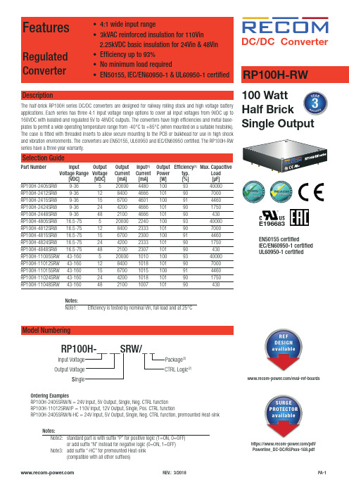
FeaturesRegulated Converter• 4:1 wide input range• 3kVAC reinforced insulation for 110Vin 2.25kVDC basic insulation for 24Vin & 48Vin • Efficiency up to 93%• No minimum load required• EN50155, IEC/EN60950-1 & UL60950-1 certifiedDescriptionThe half-brick RP100H series DC/DC converters are designed for railway rolling stock and high voltage battery applications. Each series has three 4:1 input voltage range options to cover all input voltages from 9VDC up to 160VDC with isolated and regulated 5V to 48VDC outputs. The converters have high efficiencies and metal base-RP100H-RW DC/DC Converter100 Watt Half BrickEN50155 certifiedIEC/EN60950-1 certified UL60950-1 certifiedE196683RP100H-2415SRW 9-36 15 6700 4601 100 91 4460RP100H-2424SRW 9-36 24 4200 4666 101 90 1750RP100H-2448SRW 9-36 48 2100 4666 101 90 430RP100H-4805SRW 16.5-75 5 20000 2240 100 93 40000RP100H-4812SRW 16.5-75 12 8400 2333 101 90 7000RP100H-4815SRW 16.5-75 15 6700 2300 100 91 4460RP100H-4824SRW 16.5-75 24 4200 2333 101 90 1750RP100H-4848SRW 16.5-75 48 2100 2307 101 90 430RP100H-11005SRW 43-160 5 20000 1010 100 93 40000RP100H-11012SRW 43-160 12 8400 1018 101 90 7000RP100H-11015SRW 43-160 15 6700 1015 100 91 4460RP100H-11024SRW 43-160 24 4200 1018 101 90 1750RP100H-11048SRW 43-160 48 2100 1007 101 90 430Ordering ExamplesRP100H-2405SRW/N = 24V Input, 5V Output, Single, Neg. CTRL function RP100H-11012SRW/P = 110V Input, 12V Output, Single, Pos. CTRL functionRP100H-2405SRW/N-HC = 24V Input, 5V Output, Single, Neg. CTRL function, premounted Heat-sinkModel NumberingInput Voltage Output VoltageS ingleRP100H-__ __SRW/_ _Notes:Note2: standard part is with suffix “P” for positive logic (1=ON, 0=OFF) or add suffix “N” instead for negative logic (0=ON, 1=OFF) Note3: add suffix “-HC” for premounted Heat-sink CTRL Logic (2)Package (3)Notes:Note1:Efficiency is tested by nominal Vin, full load and at 25°Chttps:///pdf/Powerline_DC-DC/RSPxxx-168.pdf/eval-ref-boardsSpecifications (measured @Ta = 25°C, resistive load, nominal Vin and rated Iout unless otherwise noted)Specifications (measured @Ta = 25°C, resistive load, nominal Vin and rated Iout unless otherwise noted)RP100H-4805SRW708090100Efficiency vs. Output CurrentPower up Start-up CharacteristicON/OFF Control Start-up Rise CharacteristicSpecifications (measured @Ta = 25°C, resistive load, nominal Vin and rated Iout unless otherwise noted)Efficiency vs. Input Voltage60708090100708010090RP100H-11005SRWEfficiency vs. Output CurrentPower up Start-up CharacteristicSpecifications (measured @Ta = 25°C, resistive load, nominal Vin and rated Iout unless otherwise noted)OUTPUT TRIM Typical Output Ripple and NoisePower up Start-up CharacteristicOutput Voltage TrimmingRP100H-RW converters offer the feature of trimming the output voltage over a certain range around the nominal value by using external trim resistors. The values for trim resistors shown in trim tables below are according to standard E96 values; therefore, the specified voltage may slightly vary; they also can be calculated with below shown equation.TRIM DOWNTRIM UPTRIM-Sense+SenseSpecifications (measured @Ta = 25°C, resistive load, nominal Vin and rated Iout unless otherwise noted)OUTPUT TRIMRP100H-xx05SRWRP100H-xx12SRWRP100H-xx15SRWRP100H-xx24SRWRP100H-xx48SRWTrim Down all Vout‘sTrim up 12345678910%Vout = 5.05 5.10 5.15 5.20 5.25 5.30 5.35 5.4 5.45 5.50Volts R 1 = 30915810578.763.453.646.440.236.533.2kOhms Trim up 12345678910%Vout =12.1212.2412.3612.4812.6012.7212.8412.9613.0813.20Volts R 1 = 88745330122618215413311810595.3kOhms Trim up 12345678910%Vout =15.1515.3015.4515.6015.7515.9016.0516.2016.3516.50Volts R 1 = 1130576383294237196169150137124kOhms Trim up 12345678910%Vout =24.2424.4824.7224.9625.2025.4425.6825.9226.1626.40Volts R U = 1870953634487392324280249226205kOhms Trim up 12345678910%Vout =48.4848.9649.4449.9250.4050.8851.3651.8452.3252.80Volts R 1 = 3830196013001000806681576511464422kOhms Trim down 12345678910%R 2 = 97.647.531.623.217.814.712.110.59.098.06kOhms Trim down 11121314151617181920%R 2 =7.156.345.765.114.644.223.923.573.243.01kOhmsTrim CalculationVout = Output VoltageR 1 =100*Vout+D Vout * Vout)- (100+2D Vout) k Ω D Vout = Output Voltage Trim in %1.225*D Vout D VoutR1 =trim up resistorR2 = trim down resistor R 2 = 100 - 2 k ΩD Vout Practical Example:Trim Up:Vout = 5V, D Vout = 10% (5.5V)R 1 =100*Vout+D Vout * Vout) - (100+2D Vout) k Ω = 100*5 +10*5 - 100+2*10= 44.89 - 12 = 32.9k Ω 1.225*D Vout D Vout 1.225*10 10Trim down:Vout = 5V, D Vout = -10% (4.5V)R 2 = 100 - 2 k Ω = 100 - 2 = 8.06k ΩD Vout 10Specifications (measured @Ta = 25°C, resistive load, nominal Vin and rated Iout unless otherwise noted)REGULATIONSParameter Condition ValueOutput Accuracy±1.0%Line Regulation low line to high line at full load±0.1% Load Regulation0% to 100% load0.1% Transient Response25% load step change200µs typ.; 250µs max.Transient Response to Dynamic Load Change from 100% to 75% to 100% of Full Load at nom.VinRP100H-4805SRWRP100H-2405SRWRP100H-11005SRWSpecifications (measured @Ta = 25°C, resistive load, nominal Vin and rated Iout unless otherwise noted)ENVIRONMENTALParameterCondition ValueOperating Case Temperature Range refer to derating graphMaximum Case Temperature 105°CTemperature Coefficient ±0.02%/°C max.Thermal Impedance vertical direction by natural convection (0.1m/s) without Heat-sink vertical direction by natural convection (0.1m/s) with Heat-sink6.7°C/W 4.7°C/W Operating Humidity 5% - 95% RHPollution Degree PD2Shock according to EN61373 standard Thermal Shock according to MIL-STD-810F standardVibrationaccording to EN61373 standardFire protection on railway vehicles according to EN45545-2, 2013 standardMTBFaccording to MIL-HDBK-217F standard, 25°C408.7 x 103 hoursPROTECTIONSParameterConditionValueShort Circuit Protection (SCP)below 100m Ωcontinuous, automatic recovery Over Voltage Protection (OVP)% of nom. Vout115%-130%, Hiccup Mode Over Load Protection (OLP)% Iout rated24Vin, 48Vin 110Vin120%-150%, Hiccup Mode 150% typ., Hiccup ModeOver Temperature Protection (OTP)+110°C to +120°C Isolation Voltage110VinI/P to O/P I/P or O/P to Case 3kVAC/1minute 1.5kVAC/1minute 24Vin, 48VinI/P to O/P I/P or O/P to Case2.25kVDC/1minute 1.6kVDC/1minuteIsolation Resistance 500 VDC1G Ω min.Isolation Capacitance 2500pF max.Isolation Grade110 Vin 24Vin, 48Vin reinforced insulationbasic insulationThermal CalculationNotes:Note4: Refer to local wiring regulations if input over-current protection is also required. Recommended fuse: T35A slow blow.R thcase-ambient = 6.7°C/W (vertical) T case = Case Temperature R thcase-ambientHC = 4.7°C/W (vertical) T ambient = Environment Temperature P dissipation = Internal lossesR thcase-ambient = T case - T ambientP IN = Input PowerP dissipationP OUT = Output Power h = Efficiency under given Operating ConditionsP dissipation = P IN - P OUT = P OUTapp- P OUTapp R thcase-ambient = Thermal Impedance h Practical Example:Take the RP100H-2405SRW with 9V input Voltage and 50% load. What is the maximum ambient operating temperature? Use converter vertical in application without airflow.Eff min = 91% @ V nomP OUT = 100W P OUTapp = 100 x 0.5 = 50W h = 91% (Efficiency vs. Load Graph)without Heat-sink with Heat-sinkR th = T casemax - T amb --> 6.7°C/W = 105-T amb R thHC = T casemax - T amb--> 4.7°C/W = 105-T amb P dissipation 4.95W P dissipation4.95W T amb = 72°C T ambHC = 82°CSpecifications (measured @Ta = 25°C, resistive load, nominal Vin and rated Iout unless otherwise noted)Specifications (measured @Ta = 25°C, resistive load, nominal Vin and rated Iout unless otherwise noted)DC/DC ConverterSpecifications (measured @Ta = 25°C, resistive load, nominal Vin and rated Iout unless otherwise noted)RP100H-RWSeriesConducted Emission EN55022 Class AConducted Emission EN55022 Class AC4C5C6C7C8Shield PlaneL1C18+V INEMI Filtering according to EN55022/11 Class A and EN50121-1 (110Vin)DC/DC ConverterSpecifications (measured @Ta = 25°C, resistive load, nominal Vin and rated Iout unless otherwise noted)RP100H-RWSeriescontinued on next pageEMI Filtering according to EN55022/11 Class B (24Vin and 48Vin)Shield Plane100-110xxSRW, Class BNNC6C9C8C3C4CaseL2C7C19C20Shield PlaneC12C13C14C10C11C16C2C4L1L2C5C8C6C7C11C3Conducted Emission EN55022 Class ADC/DC ConverterSpecifications (measured @Ta = 25°C, resistive load, nominal Vin and rated Iout unless otherwise noted)RP100H-RWSeriesEMI Filtering according to EN55022/11 Class B (110Vin)C8Shield PlaneShield PlaneC9C1C2C3C11C12C10CaseL1C4C5C8C13C14C17C9C19C3C4L1L2C12C10C11C15C15Shield PlaneC9C10C12Conducted Emission EN55022 Class BSpecifications (measured @Ta = 25°C, resistive load, nominal Vin and rated Iout unless otherwise noted)Specifications (measured @Ta = 25°C, resistive load, nominal Vin and rated Iout unless otherwise noted)The product information and specifications may be subject to changes even without prior written notice.The product has been designed for various applications; its suitability lies in the responsibility of each customer. The products are not authorized for use in safety-critical applications without RECOM’s explicit written consent. A safety-critical application is an application where a failure may reasonably be expected to endanger or cause loss of life, inflict bodily harm or damage property. The applicant shall indemnify and hold harmless RECOM, its affiliated companies and its representatives against any damage claims in connection with the unauthorizeduse of RECOM products in such safety-critical applications.PACKAGING INFORMATIONParameterTypeValuePackaging Dimension traywithout Heat-sink with Heat-sink157.0 x 88.0 x 12.8mm 157.0 x 88.0 x 24.8mmPackaging Quantity 2pcs.Storage Temperature Range -55°C to +125°C Storage Humidity5% - 95% RH。
TMTT测试设定
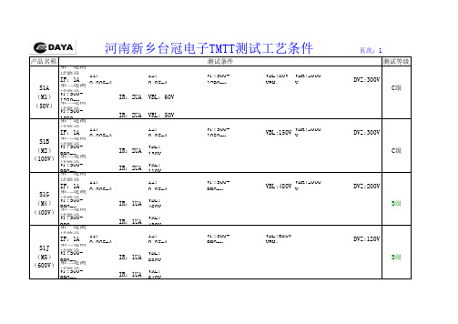
产品名称测试等级第一道测试箱设定:IF:1A I1:0.005mA I2:0.05mA VF:500-1290mvVBL:80V V VBH:2000VDVZ:300VS1A第二道测试箱设定:C级(M1)VF:500-1280mv IR:2UA VBL:60V (50V)第三道测试箱设定:VF:500-1280mv IR:2UA VRL:50V 第一道测试箱设定:IF:1A I1:0.005mA I2:0.05mA VF:500-1050mvVBL:150V VBH:2000VDVZ:300VS1B 第二道测试箱设定:(M2)VF:500-990mv IR:2UA VBL:130V C级(100V)第三道测试箱设定:VF:500-990mv IR:2UA VRL:110V 第一道测试箱设定:IF:1A I1:0.005mA I2:0.05mA VF:500-990mvVBL:480V VBH:2000VDVZ:200VS1G 第二道测试箱设定:(M4)VF:500-990mv IR:1UA VBL:460V B级(400V)第三道测试箱设定:VF:500-990mv IR:1UA VRL:430V 第一道测试箱设定:IF:1A I1:0.005mA I2:0.05mA VF:500-990mvVBL:680V VBH:2000VDVZ:120VS1J 第二道测试箱设定:(M5)VF:500-990mv IR:1UA VBL:660V B级(600V)第三道测试箱设定:VF:500-990mv IR:1UAVRL:640V河南新乡台冠电子TMTT测试工艺条件 页次:1测试条件产品名称测试等级第一道测试箱设定:IF:1A I1:0.005mAI2:0.05mA VF:500-990mvVBL:880V VBH:2000VDVZ:120VS1K 第二道测试箱设定:B级(M6)VF:500-990mv IR:1UA VBL:860V (800V)第三道测试箱设定:VF:500-990mv IR:1UA VRL:840V 第一道测试箱设定:IF:1A I1:0.005mAI2:0.05mA VF:500-990mvVBL:1080V VBH:2000VDVZ:100VS1M 第二道测试箱设定:B级(M7)VF:500-990mv IR:1UA VBL:1060V (1000V)第三道测试箱设定:VF:500-990mv IR:1UA VRL:1030V 第一道测试箱设定:S1M IF:1A I1:0.005mA I2:0.05mA VF:500-990mvVBL:1250V VBH:2000VDVZ:80V(M7)第二道测试箱设定:A级(TDD)VF:500-990mv IR:1UA VBL:1230V (1100V)第三道测试箱设定:(1200V)VF:500-990mv IR:1UAVRL:1220V 第一道测试箱设定:IF:1A I1:0.005mA I2:0.05mA VF:500-1100mvVBL:1720V VBH:2200VDVZ:100VM9第二道测试箱设定:A级(1600V)VF:500-1100mv IR:1UAVBL:1700V 第三道测试箱设定:VF:500-1100mv IR:1UAVRL:1650V河南新乡台冠电子TMTT测试工艺条件 页次:2测试条件产品名称测试等级第一道测试箱设定:IF:1A I1:0.005mA I2:0.05mAVF:900-1290mvVBL:80V VBH:2000VDVZ:250VIR:2UAVRL:70VRS1A第二道测试箱设定:C级(50V)TRR:150ns第三道测试箱设定:VF:900-1290mv IR:2UAVRL:60V第一道测试箱设定:IF:1A I1:0.005mA I2:0.05mAVF:900-1290mvVBL:280V VBH:2000VDVZ:150VIR:2UAVRL:260VRS1D 第二道测试箱设定:C级(200V)TRR:150ns第三道测试箱设定:VF:900-1290mv IR:2UAVRL:230V第一道测试箱设定:IF:1A I1:0.005mA I2:0.05mAVF:900-1290mvVBL:480V VBH:2000VDVZ:120VIR:1UAVRL:440VRS1G 第二道测试箱设定:B级(400V)TRR:150ns第三道测试箱设定:VF:900-1290mvIR:1UAVRL:420V河南新乡台冠电子TMTT测试工艺条件 页次:3测试条件产品名称测试等级第一道测试箱设定:IF:1A I1:0.005mA I2:0.05mAVF:900-1290mvVBL:680V VBH:2000VDVZ:100VIR:1UAVRL:640VRS1J第二道测试箱设定:B级(600V)TRR:245ns第三道测试箱设定:VF:900-1290mv IR:1UAVRL:620V第一道测试箱设定:IF:1A I1:0.005mA I2:0.05mAVF:900-1290mvVBL:880V VBH:2000VDVZ:100VIR:1UAVRL:840VRS1K 第二道测试箱设定:B级(800V)TRR:490ns第三道测试箱设定:VF:900-1290mv IR:1UAVRL:820V第一道测试箱设定:IF:1A I1:0.005mA I2:0.05mAVF:900-1290mvVBL:1080V VBH:2000VDVZ:100VIR:1UAVRL:1050VB级RS1M 第二道测试箱设定:(1000V)TRR:490ns第三道测试箱设定:VF:900-1290mvIR:1UAVRL:1030V河南新乡台冠电子TMTT测试工艺条件 页次:4测试条件产品名称测试等级第一道测试箱设定:RS1MIF:1AI1:0.005mA I2:0.05mAVF:900-1290mvVBL:1250V VBH:2000VDVZ:80V(TDD)IR:1UAVRL:1230V(1100V)第二道测试箱设定:A级(1200V)TRR:490ns第三道测试箱设定:VF:900-1290mv IR:1UAVRL:1220V第一道测试箱设定:IF:1A I1:0.005mA I2:0.05mAVF:500-990mvVBL:80V VBH:2000VDVZ:250VIR:2UAVRL:70VUS1A第二道测试箱设定:C级(50V)TRR:50ns第三道测试箱设定:VF:500-990mv IR:2UAVRL:60V第一道测试箱设定:IF:1A I1:0.005mA I2:0.05mAVF:500-990mvVBL:280V VBH:2000VDVZ:120VIR:1UAVRL:260VUS1D第二道测试箱设定:B级(200V)TRR:50ns第三道测试箱设定:VF:500-980mvIR:1UAVRL:220V河南新乡台冠电子TMTT测试工艺条件 页次:5测试条件产品名称测试等级第一道测试箱设定:IF:1A I1:0.005mA I2:0.05mAVF:900-1280mvVBL:480V VBH:2000VDVZ:100VIR:1UAVRL:460VUS1G第二道测试箱设定:B级(400V)TRR:50ns第三道测试箱设定:VF:900-1280mv IR:1UAVRL:420V第一道测试箱设定:IF:1A I1:0.005mA I2:0.05mAVF:1100-1680mvVBL:680V VBH:2000VDVZ:100VIR:1UAVRL:660VUS1J第二道测试箱设定:B级(600V)TRR:50ns第三道测试箱设定:VF:1100-1680mv IR:1UAVRL:620V第一道测试箱设定:IF:1A I1:0.005mA I2:0.05mAVF:1100-1680mvVBL:880V VBH:2000VDVZ:120VIR:1UAVRL:860VUS1K第二道测试箱设定:B级(800V)TRR:75ns第三道测试箱设定:VF:1100-1680mvIR:1UAVRL:820V河南新乡台冠电子TMTT测试工艺条件 页次:6测试条件产品名称测试等级第一道测试箱设定:IF:1A I1:0.005mA I2:0.05mAVF:1100-1680mvVBL:1080V VBH:2000VDVZ:100VIR:1UAVRL:1050VUS1M第二道测试箱设定:B级(1000V)TRR:75ns第三道测试箱设定:VF:1100-1680mv IR:1UAVRL:1020V第一道测试箱设定:US1MIF:1AI1:0.005mA I2:0.05mAVF:1100-1680mvVBL:1080V VBH:2000VDVZ:80V(TDD)IR:1UA VRL:1050V(1100V)第二道测试箱设定:A级(1200V)TRR:75ns第三道测试箱设定:VF:1100-1680mv IR:1UAVRL:1020V第一道测试箱设定:IF:1A I1:0.005mA I2:0.05mAVF:500-945mvVBL:80V VBH:2000VDVZ:200VIR:2UAVRL:70VES1A第二道测试箱设定:C级(50V)TRR:35ns第三道测试箱设定:VF:500-945mvIR:2UAVRL:60V河南新乡台冠电子TMTT测试工艺条件 页次:7测试条件产品名称测试等级第一道测试箱设定:IF:1A I1:0.005mA I2:0.05mAVF:500-945mvVBL:280V VBH:2000VDVZ:120VIR:1UAVRL:260VES1D第二道测试箱设定:B级(200V)TRR:35ns第三道测试箱设定:VF:500-945mv IR:1UAVRL:230V第一道测试箱设定:IF:1A I1:0.005mA I2:0.05mAVF:850-1240mvVBL:480V VBH:2000VDVZ:120VIR:1UAVRL:460VES1G第二道测试箱设定:B级(400V)TRR:35ns第三道测试箱设定:VF:850-1240mv IR:1UAVRL:420V第一道测试箱设定:IF:1A I1:0.005mA I2:0.05mAVF:1100-1680mvVBL:680V VBH:2000VDVZ:100VIR:1UAVRL:660VES1J第二道测试箱设定:A级(600V)TRR:35ns第三道测试箱设定:VF:1100-1680mvIR:1UAVRL:620V河南新乡台冠电子TMTT测试工艺条件 页次:8测试条件产品名称测试等级第一道测试箱设定:IF:1AI1:0.2mAI2:1mAVF:420-540mvVBL:25V VBH:100VDVZ:5VSS12第二道测试箱设定:B级(20V)VF:420-540mvIR:100UAVBL:25V第三道测试箱设定:VF:420-540mv IR:100UA VRL:22V第一道测试箱设定:IF:1AI1:0.2mAI2:1mA VF:420-540mv VBL:45V VBH:100V DVZ:5VSS14第二道测试箱设定:A级(40V)VF:420-540mvIR:100UAVBL:45V第三道测试箱设定:VF:420-540mv IR:100UA VRL:42V第一道测试箱设定:IF:1AI1:0.2mAI2:1mA VF:450-740mv VBL:65V VBH:100V DVZ:5VSS16第二道测试箱设定:A级(60V)VF:450-740mvIR:100UAVBL:65V第三道测试箱设定:VF:450-740mvIR:100UA VRL:62V河南新乡台冠电子TMTT测试工艺条件 页次:9测试条件产品名称测试等级第一道测试箱设定:IF:1AI1:0.2mAI2:1mAVF:650-840mvVBL:85V VBH:150VDVZ:5VSS18第二道测试箱设定:A级(80V)VF:650-840mvIR:100UAVBL:85V第三道测试箱设定:VF:650-840mv IR:100UA VRL:82V第一道测试箱设定:IF:1AI1:0.2mAI2:1mA VF:650-840mv VBL:105V VBH:150V DVZ:5VSS110第二道测试箱设定:A级(100V)VF:650-840mvIR:100UAVBL:105V第三道测试箱设定:VF:650-840mv IR:100UA VRL:102V第一道测试箱设定:IF:2AI1:0.2mAI2:1mA VF:420-540mv VBL:25V VBH:100V DVZ:5VSS22第二道测试箱设定:A级(20V)VF:420-540mvIR:100UAVBL:25V第三道测试箱设定:VF:420-540mvIR:100UA VRL:22V河南新乡台冠电子TMTT测试工艺条件 页次:10测试条件产品名称测试等级第一道测试箱设定:IF:2AI1:0.2mA I2:1mA VF:420-540mv VBL:45V VBH:100V DVZ:5V SS24第二道测试箱设定:A级(40V)VF:420-540mvIR:100UA VBL:45V 第三道测试箱设定:VF:420-540mvIR:100UA VRL:42V 第一道测试箱设定:IF:2AI1:0.2mA I2:1mA VF:500-680mv VBL:65V VBH:100V DVZ:5V SS26第二道测试箱设定:A级(60V)VF:500-680mvIR:100UA VBL:65V 第三道测试箱设定:VF:500-680mvIR:100UA VRL:62V 第一道测试箱设定:IF:2AI1:0.2mA I2:1mA VF:650-830mv VBL:85V VBH:150V DVZ:5V SS28第二道测试箱设定:A级(80V)VF:650-830mvIR:100UA VBL:85V 第三道测试箱设定:VF:650-830mv IR:100UA VRL:82V河南新乡台冠电子TMTT测试工艺条件 页次:11测试条件产品名称测试等级第一道测试箱设定:IF:2AI1:0.2mA I2:1mA VF:650-830mv VBL:105V VBH:150V DVZ:5V SS210第二道测试箱设定:A级(100V)VF:650-830mvIR:100UA VBL:105V 第三道测试箱设定:VF:650-830mvIR:100UA VRL:102V 第一道测试箱设定:IF:3AI1:0.2mA I2:1mA VF:420-540mv VBL:25V VBH:100V DVZ:5V SS32第二道测试箱设定:A级(20V)VF:420-540mvIR:100UA VBL:25V 第三道测试箱设定:VF:420-540mvIR:100UA VRL:22V 第一道测试箱设定:IF:3AI1:0.2mA I2:1mA VF:420-540mv VBL:45V VBH:100V DVZ:5V SS34第二道测试箱设定:A级(40V)VF:420-540mvIR:100UA VBL:45V 第三道测试箱设定:VF:420-540mv IR:100UA VRL:42V河南新乡台冠电子TMTT测试工艺条件 页次:12测试条件产品名称测试等级第一道测试箱设定:IF:3AI1:0.2mA I2:1mA VF:500-740mv VBL:65V VBH:100V DVZ:5V SS36第二道测试箱设定:A级(60V)VF:520-740mvIR:100UA VBL:65V 第三道测试箱设定:VF:520-740mvIR:100UA VRL:62V 第一道测试箱设定:IF:3AI1:0.2mA I2:1mA VF:650-840mv VBL:85V VBH:150V DVZ:5V SS38第二道测试箱设定:A级(80V)VF:650-840mvIR:100UA VBL:85V 第三道测试箱设定:VF:650-840mvIR:100UA VRL:82V 第一道测试箱设定:IF:3AI1:0.2mA I2:1mA VF:650-840mv VBL:105V VBH:150V DVZ:5V SS310第二道测试箱设定:A级(100V)VF:650-840mvIR:100UA VBL:105V 第三道测试箱设定:VF:650-840mv IR:100UA VRL:102V 河南新乡台冠电子TMTT测试工艺条件 页次:13测试条件。
19073耐压测试仪说明书
19073耐压测试仪说明书19073耐压测试仪是一种用于测试电气设备或电子产品绝缘性能的仪器。
它通过对设备进行高压电流的施加,来检测设备是否能够在正常工作条件下保持电气绝缘。
本文将详细介绍19073耐压测试仪的使用方法、技术参数以及注意事项。
一、使用方法:1. 连接电源:将耐压测试仪的电源线连接到电源插座上,并确保电源电压与设备要求的电源电压相匹配。
2. 连接被测设备:将被测设备的电源线连接到耐压测试仪的电源输入端,确保连接牢固。
3. 设置参数:根据被测设备的要求,设置耐压测试仪的输出电压和测试时间。
可以通过仪器上的按键或旋钮进行设置。
4. 开始测试:按下仪器上的启动按钮,耐压测试仪开始给被测设备施加高压电流。
5. 监测测试结果:在测试过程中,耐压测试仪会监测被测设备的绝缘电阻和漏电流等参数。
如果测试结果正常,仪器会显示通过提示;如果测试结果异常,仪器会显示失败提示。
二、技术参数:1. 输出电压:19073耐压测试仪的输出电压范围为0-5000V,可以根据被测设备的要求进行调整。
2. 测试时间:耐压测试仪可以设置的测试时间范围为0-999.9s,可以根据被测设备的要求进行调整。
3. 绝缘电阻:耐压测试仪能够监测的绝缘电阻范围为0.01MΩ-9999MΩ,精度为±(3%+5d)。
4. 漏电流:耐压测试仪能够监测的漏电流范围为0.01mA-20mA,精度为±(3%+5d)。
三、注意事项:1. 在使用耐压测试仪进行测试之前,必须确保设备已经断开电源,并且处于安全状态。
2. 在进行测试时,必须按照正确的操作步骤进行,避免操作失误导致人身或设备安全事故。
3. 在测试过程中,应严格按照设备的要求设置输出电压和测试时间,避免对设备造成过高的电压或长时间的电流冲击。
4. 如果测试结果异常,应立即停止测试,并检查设备的接线是否正确或设备本身是否存在故障。
5. 耐压测试仪在使用过程中,应定期进行校准和维护,确保测试结果的准确性和稳定性。
罗森伯格高频技术有限公司50欧姆压力计试验仪试验套件说明书

50 ΩD i e s e s D o k u m e n t i s t u r h e b e r r e c h t l i c h g e s c h üt z t ● T h i s d o c u m e n t i s p r o t e c t e d b y c o p y r i g h t ● R o s e n b e r g e r H o c h f r e q u e n z t e c h n i k G m b H & C o . K G.10/6.1Picture may differ from original product.DevicePart numberQuantityCalibration Option aGauge plug (including gauge block)06W00S-000 1 FC Gauge jack(including gauge block)06W00K-0001FCa.See “Declaration of calibration options” for explanation.06W00S-00006W00K-000Gauge block 5.28 mm5.28 mmGauge range 5.28 mm ± 0.5 mm5.28 mm ± 0.5 mmScale gradation1 µm 1 µm Limit of measurement error 1 ≤ 10 µm2 ≤ 10 µm3 Typical measurement error 1 ≤ 6 µm 2 ≤ 6 µm 3 Measuring force1.5 N 1.5 N1 When zeroed with gauge block 25.24 mm to 5.40 mm 35.16 mm to 5.32 mm50 ΩD i e s e s D o k u m e n t i s t u r h e b e r r e c h t l i c h g e s c h üt z t ● T h i s d o c u m e n t i s p r o t e c t e d b y c o p y r i g h t ● R o s e n b e r g e r H o c h f r e q u e n z t e c h n i k G m b H & C o . K G.10/6.1This kit is delivered with • Calibration CertificateDetails see “Declaration of calibration options” • Kit Info CardHandling precautions and mechanical information. • Operating ManualFactory CalibrationStandard delivery for this gauge includes a Factory Calibration. The Calibration Certificate issued reports individual mechanical calibration results, traceable to national / international standards.Accredited Calibration Not available.For further, more detailed information see application note AN001 on the Rosenberger homepage.Recommendation 12 monthsFor further, more detailed information please visit our homepage .DraftDate Approved DateRev. Engineering change numberName Date Martin Moder 23/11/15Roland Neuhauser06.11.18c0018-0004M.Ruf06.11.18While the information has been carefully compiled to the best of our knowledge, nothing is intended as representation or warranty on our part and no statement herein shall be construed as recommendation to infringe existing patents. In the effort to improve our products, we reserve the right to make changes judged to be necessary.。
耐压测试仪技术参数
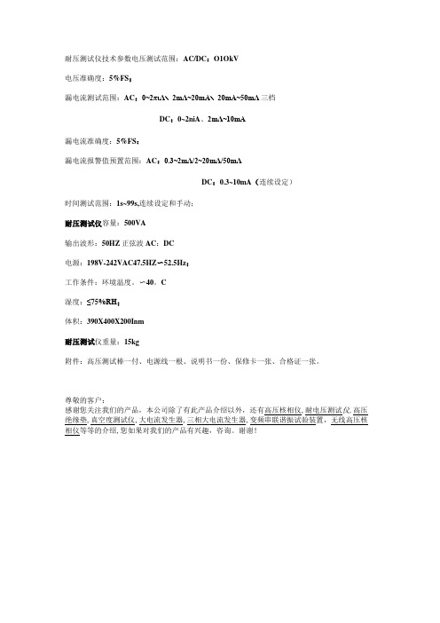
耐压测试仪技术参数电压测试范围:AC/DC:O1OkV
电压准确度:5%FS;
漏电流测试范围:AC:0~2πιΛ∖2mΛ~20mA∖20mA~50mΛ三档
DC:0~2niA、2mΛ~10mA
漏电流准确度:5%FS:
漏电流报警值预置范围:AC:0.3~2mΛ/2~20mΛ/50mΛ
DC:0.3~10mA(连续设定)
时间测试范围:1s~99s,连续设定和手动;
耐压测试仪容量:500VA
输出波形:50HZ正弦波AC:DC
电源:198V-242VAC47.5HZ〜52.5Hz;
工作条件:环境温度。
〜40。
C
湿度:≤75%RH;
体积:390X400X200Inm
耐压测试仪重量:15kg
附件:高压测试棒一付、电源线一根、说明书一份、保修卡一张、合格证一张。
尊敬的客户:
感谢您关注我们的产品,本公司除了有此产品介绍以外,还有高压核相仪,耐电压测试仪,高压绝缘垫,真空度测试仪,大电流发生器,三相大电流发生器,变频串联谐振试验装置,无线高压核相仪等等的介绍,您如果对我们的产品有兴趣,咨询。
谢谢!。
非洲猪瘟快检设备

非洲猪瘟快检设备تادعمةيقيرفلأافشكلاريزانخلا非洲猪瘟快检设备JD-PCR ىمحعيرسلا竞道非洲猪瘟检测仪配套非洲猪瘟病毒荧光pcr检测试剂盒、非洲猪瘟病毒荧光pcr核酸检测试剂盒均已经获得农业农村部产品批准,可以满意非洲猪瘟核酸现场快速检测需求。
可定量快速畜牧类疾病诊断如非洲猪瘟、禽感、猪瘟、猪蓝耳、伪狂犬等疾病,广泛应用于养殖场、屠宰场、食品加工厂、肉产品深加工企业、农业农村部、畜牧局、检验检疫单位使用。
仪器特点1.体积小,重量轻,易于携带。
轻松满意外出试验的需求。
2.内置7寸高清电容屏PDA,触屏操作,简便快捷。
3.Marlow高品质Peltier制冷片,结合德国PT1000温度传感器以及电性电阻加热补偿边缘的温度掌握模式,大升温速度7℃,大降温速度5℃,大大缩短试验时间。
4.整板3s快速采光模式,保证明验结果孔位全都性。
5.简洁直观的软件引导,轻松开启检测试验。
非洲猪瘟PCR检测仪应用领域□ 基础科学讨论□ 病原体检测□ 肉制品掺假□ 转基因检测□ 食品平安检测□ 药物开发及合理用药□ 基因表达□ 水体监测四、技术参数样品容量:8x0.2ml、支持8联管适用耗材:常见透亮PCR 耗材,8x0.2ml 排管,0.2ml 单管反应体系:5-120ul反应模式体系加热/制冷模块:进口半导体热电模块温度掌握范围:4C-99℃升降温平均速率2C/秒温控精度:0.1C温度匀称性: 0.2C温控区域数量:多点(2 点)梯度数:0 个梯度温度范围:无梯度孔数:无激发光源:免维护led激发光波长范围:400-700nm检测部件:进口光电检测器检测通道数:标配 1通道(FAM)、高配(选配)(FAM、VIC)适用染料和探针:FAM/SYBR Green I, VIC/HEX/CY3(选配), ROX/Texas Red(选配), Cy5,TAMARA(选配)软件功能:荧光定量 PCR 系统软件; 实时扩增反应曲线功能;特定标本实时反应曲线显示;数据分析功能;阴阳结果自动判定功能;图形化显示功能。
TH9320交直流耐压绝缘电阻测试仪器说明书
TH9310/20 系列用户手册 Ver1.1.6
------------------------------
2014.6
TH9310/20 系列仪器使用说明书
Ver1.1.6
目录
第 1 章 开箱安装 ______________________________________________________________ 1 1.1 开箱检查 _____________________________________________________________ 1 1.2 使用注意事项 _________________________________________________________ 2 1.3 移动时的注意要点 _____________________________________________________ 3 1.4 检查电源和保险丝 _____________________________________________________ 3 1.5 连接交流电源线 _______________________________________________________ 4 1.6 接地 _________________________________________________________________ 4 1.7 操作检查 _____________________________________________________________ 5 1.8 仪器的其它特性 _______________________________________________________ 5 第 2 章 操作规范和措施 ________________________________________________________ 6 2.1 禁止的操作行为 _______________________________________________________ 6 2.2 紧急情况的处理 _______________________________________________________ 6 2.3 测试中的预防措施 _____________________________________________________ 6 2.4 高压测试警告 _________________________________________________________ 7 2.5 有故障仪器的危险状态处理 _____________________________________________ 8 2.6 保证长时间无故障使用的条件 ___________________________________________ 8 2.7 日常检查 _____________________________________________________________ 8 第 3 章 仪器面板概述 __________________________________________________________ 9 3.1 前面板说明 ___________________________________________________________ 9 3.2 后面板说明 __________________________________________________________ 11 3.3 多通道模块说明 ______________________________________________________ 12 3.4 仪器性能概述 ________________________________________________________ 13 第 4 章 基本操作 _____________________________________________________________ 17 4.1 仪器界面结构概述 ____________________________________________________ 17 4.2 面板功能界面和参数说明 ______________________________________________ 18 4.2.1 SETUP 测量设置 _______________________________________________ 20 4.2.2 TEST 测试界面 ________________________________________________ 21 4.2.3 SYSTEM 系统界面 ______________________________________________ 22 4.2.4 FILE 文件存储界面。___________________________________________ 24 4.3 测试项目界面和参数说明 ______________________________________________ 26 4.3.1 AC 交流耐压测试参数设定 ______________________________________ 26 4.3.2 DC 直流耐压测试参数设定 ______________________________________ 27 4.3.3 IR 绝缘电阻测试参数设定 _______________________________________ 28 4.3.4 OS 开短路检测测试参数设定 ____________________________________ 29 4.3.5 MF 多路辅助控制设定 __________________________________________ 30 4.4 测试功能原理与使用说明 ______________________________________________ 31 4.4.1 启动测试 _____________________________________________________ 31 4.4.2 测试时延 _____________________________________________________ 31 4.4.3 电压上升 _____________________________________________________ 32
贝奇电子 CH2700 系列电源综合测试仪操作手册说明书

使用说明书OPERATION MANUALCH2700系列电源综合测试仪Power Supply Parameter TesterVer1.0常州市贝奇电子科技有限公司BEICH ELECTRONIC TECHNOLOGY CO.,LTD.注意事项:本说明书版权归常州市贝奇电子科技有限公司所有,贝奇电子保留所有权利。
未经贝奇电子书面同意,不得对本说明书的任何部分进行影印、复制或转译。
本说明书适用于CH2700系列电源综合测试仪本说明书包含的信息可能随时修改,恕不另行通知。
最新的说明书电子文档可以从贝奇电子官方网站下载:2017年3月……………………………………..第一版公司声明本说明书所描述的可能并非仪器所有内容,贝奇电子有权对本产品的性能、功能、内部结构、外观、附件、包装物等进行改进和提高而不作另行说明!由此引起的说明书与仪器不一致的困惑,可与我公司联系。
安全警告:在使用操作和维护本仪器的任何过程中,务必遵守各项安全防护措施。
如果忽视和不遵守这些安全措施及本手册中的警告,不但会影响仪器性能,更可能导致仪器的直接损坏,并可能危及人身安全。
对于不遵守这些安全防范措施而造成的后果,贝奇电子科技有限公司不承担任何后果。
触电危险操作测试与维护仪器时谨防触电,非专业人员请勿擅自打开机箱,专业人员如需更换保险丝或进行其它维护,务必先拔去电源插头,并在有人员陪同情况下进行。
即使已拔去电源插头,电容上电荷仍可能会有危险电压,应稍过几分钟待放电后再行操作。
请勿擅自对仪器内部电路及元件进行更换和调整!输入电源请按本仪器规定的电源参数要求使用电源,不符合规格的电源输入可能损坏本仪器。
更换保险丝请使用相同规格远离爆炸性气体环境电子仪器不可以在易燃易爆气体环境中使用,或者在含有腐蚀性气体或烟尘环境中使用,避免带来危险。
其它安全事项请不要向本仪器的测试端子以及其它输入输出端子随意施加外部电压源或电流源。
输入端切勿输入交流电压。
飞鸟1555和1550C电阻性电抗试验仪商品说明书
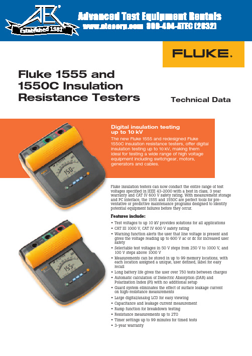
Technical DataFluke 1555 and 1550C Insulation Resistance TestersFluke insulation testers can now conduct the entire range of test voltages specified in IEEE 43-2000 with a best in class, 3 yearwarranty and CAT IV 600 V safety rating. With measurement storage and PC interface, the 1555 and 1550C are perfect tools for pre-ventative or predictive maintenance programs designed to identify potential equipment failures before they occur.Features include:• Test voltages to up 10 kV provides solutions for all applications • CAT III 1000 V, CAT IV 600 V safety rating• Warning function alerts the user that line voltage is present andgives the voltage reading up to 600 V ac or dc for increased user safety• Selectable test voltages in 50 V steps from 250 V to 1000 V, and 100 V steps above 1000 V• Measurements can be stored in up to 99 memory locations, with each location assigned a unique, user defined, label for easy recall• Long battery life gives the user over 750 tests between charges • Automatic calculation of Dielectric Absorption (DAR) and Polarization Index (PI) with no additional setup• Guard system eliminates the effect of surface leakage current on high-resistance measurements• Large digital/analog LCD for easy viewing• Capacitance and leakage current measurement • Ramp function for breakdown testing • Resistance measurements up to 2TΩ• Timer settings up to 99 minutes for timed tests • 3-year warrantyDigital insulation testing up to 10 kVThe new Fluke 1555 and redesigned Fluke1550C insulation resistance testers, offer digital insulation testing up to 10 kV, making them ideal for testing a wide range of high voltage equipment including switchgear, motors, generators and cables.19812 Fluke Corporation Fluke 1555 and 1550C Insulation Resistance TestersFluke CorporationPO Box 9090, Everett, WA USA 98206Fluke Europe B.V.PO Box 1186, 5602 BD Eindhoven, The NetherlandsFor more information call:In the U.S.A. (800) 443-5853 or Fax (425) 446-5116In Europe/M-East/Africa +31 (0) 40 2675 200 or Fax +31 (0) 40 2675 222In Canada (800)-36-FLUKE or Fax (905) 890-6866From other countries +1 (425) 446-5500 or Fax +1 (425) 446-5116Web access: ©2005-2010 Fluke Corporation.Specifications subject to change without notice. Printed in U.S.A. 10/2010 1629685G D-EN-N Modification of this document is not permitted without written permission from Fluke Corporation.Fluke. Keeping your world up and running.Ordering information1550C 5 kV Insulation Tester 1555 10 kV Insulation Tester 1550C/Kit 5 kV Insulation Tester Kit 1555/Kit 10 kV Insulation Tester KitOptional accessoriesTL1550EXT 25 foot extendedtest lead setIncluded accessoriesTest Cables with Alligator Clips (red, black, green)Infrared adapter with interface cable FlukeView Forms Basic CD-ROM AC Power CordSoft Carrying Case (base models only)English ManualUsers Manual on CD-ROM Quick Reference CardSoftware License Agreement Registration CardFlukeView Forms Installation Guide USB-IR Cable Installation Guide IP67 Hard Case (kit only)Certificate of Calibration (kit only)Ruggedized Alligator Clips (kit and 1555 only)Software specification sFluke ViewForms basic softwarerequires a PC running Windows 2000, Windows XP and Windows Vista.SpecificationsElectrical specificationsThe tester’s accuracy is specified for one year after calibration at operating temperatures of 0 °C to 35 °C. For operating temperatures outside the range (-20 °C to 0 °C and 35 °C to 50 °C), add ± .25 % per °C, except on the 20 % bands add ± 1 % per °C.Insulation resistance measurementTest voltage (dc)RangeAccuracy (± reading)250 V< 200 kΩ200 kΩ to 5 GΩ5 GΩ to 50 GΩ> 50 GΩunspecified 5 %20 %unspecified 500 V< 200 kΩ200 kΩ to 10 GΩ10 GΩ to 100 GΩ> 100 GΩunspecified 5 %20 %unspecified 1000 V< 200 kΩ200 kΩ to 20 GΩ20 GΩ to 200 GΩ> 200 GΩunspecified 5 %20 %unspecified 2500 V< 200 kΩ200 kΩ to 50 GΩ50 GΩ to 500 GΩ> 500 GΩunspecified 5 %20 %unspecified 5000 V< 200 kΩ200 kΩ to 100 GΩ100 GΩ to 1 TΩ> 1 TΩunspecified 5 %20 %unspecified 10000 V (1555 Only)< 200 kΩ200 kΩ to 200 GΩ200 GΩ to 2 TΩ> 2 TΩunspecified 5 %20 %unspecifiedBar graph range0 to 1 TΩInsulation test voltage accuracy -0 %, +10 % at 1 mA load current Induced ac mains current rejection 2 mA maximum Charging rate for capacitive load5 seconds per μF Discharge rate for capacitive load 1.5 s/μFRangeAccuracyLeakage current measurement1 nA to2 mA ± (5 % + 2 nA)Capacitance measurement 0.01 uF to 15.00 μF ± (15 % rdg + 0.03 μF)TimerRangeResolution0 to 99 minutesSetting: 1 minute Indication: 1 second Live circuit warningWarning rangeVoltage accuracy 30 V to 660 V ac/dc, 50/60 Hz± (15 % + 2 V)General specifications。
19073耐压测试仪说明书
19073耐压测试仪说明书一、引言19073耐压测试仪是一种用于测试电气设备绝缘性能的专用仪器。
本说明书旨在向用户介绍该测试仪器的使用方法、技术参数和注意事项,以确保用户正确、安全地操作测试仪器。
二、技术参数1. 测试电压范围:0-5000V2. 测试电流范围:0-20mA3. 测试精度:±2%4. 电源要求:220V±10%,50Hz三、仪器组成19073耐压测试仪由以下几个部分组成:1. 主机:包含电源开关、测试电压和电流调节器、测试结果显示屏等功能模块。
2. 高压输出端子:用于连接待测设备的绝缘部分。
3. 接地端子:用于将测试仪器接地,确保安全可靠。
4. 连接线:用于连接主机与待测设备。
四、使用方法1. 连接电源:将测试仪器插入220V电源插座,并打开电源开关。
2. 连接待测设备:将待测设备的绝缘部分与高压输出端子连接,并确保连接牢固可靠。
3. 设置测试参数:根据待测设备的要求,通过测试仪器的电压和电流调节器设置合适的测试参数。
4. 开始测试:确保操作人员和周围环境安全后,按下测试按钮开始测试。
5. 检查测试结果:测试仪器的显示屏将显示测试结果,操作人员应仔细检查测试结果并记录。
五、注意事项1. 操作前仔细阅读本说明书,并按照操作步骤正确使用测试仪器。
2. 在测试过程中,应保持仪器和待测设备的连接牢固,避免松动或接触不良。
3. 在测试之前,应检查待测设备是否已经完全断开电源,并排除任何可能导致电击的危险因素。
4. 在测试过程中,应注意观察待测设备是否有异常情况,如异常声音、烟雾等,如有异常应立即停止测试并检查设备。
5. 禁止在高压输出端子附近进行其他操作,以免造成危险。
6. 操作人员应全程佩戴绝缘手套和绝缘鞋,并确保自身与地面良好接触。
7. 操作人员禁止触摸高压输出端子或连接线,以免触电危险。
8. 长时间不使用测试仪器时,应将其断开电源,并妥善保管。
六、维护与保养1. 每次使用后,应将测试仪器断开电源,并用干净的布擦拭仪器表面,保持干净整洁。
JK7122S多路耐压绝缘测试仪使用说明书
使用说明书JK7122S多路耐压绝缘测试仪ear2.0地址:江苏省常州市天宁区青洋北路1号新动力创业中心22栋C3电话:*************89187775 Tel**************89187775 传真:*************Fal**************主页地址: Http:电子邮件:****************Email:****************第一章 安全规则说明书内容若有改变,恕不另行通知。
说明书若有不详尽之处,请直接与本公司联系。
高电压测试前应该注意的规定和事项!!!1.1一般规定·使用本测试仪以前,请认真阅读说明书,了解操作规程和相关的安全标志,以保证安全。
·在开启本机的输入电源开关前,请先选择正确的输入电压(110V 或220V )规格。
危险标志,表示有高压输出,请避免接触。
机箱接地符号。
警告应注意所执行的操作、应用或条件均具有很高的危险性,可能导致人员受伤或死亡。
仪器所产生的电压电流足以造成人员伤害,为了防止意外伤害或死亡的发生,在移动和使用仪器时,请务必先观察清楚,然后再进行操作。
1. 2维护和保养1.2.1使用者的维护为了防止触电,非专业人员不要打开仪器的盖子。
本仪器内部所有的零件,不得私自更换。
如果仪器有异常情况发生,请寻求本公司指定经销商帮助。
1.2.2定期维护本系列测试仪、输入电源线、测试线和相关附件等每年至少要仔细检验和校验一次,以保证操作员的安全和仪器的精确性。
1.2.3使用者的修改使用者不得自行更改仪器的线路或零件,否则本公司的保证失效,并对由此产生的后果不负任何责任。
1. 3测试环境1.3.1工作位置操作本仪器时必须保证仪器放置于一般人员不能随意接触的地方。
如果因为生产线的安排而无法做到时,必须将测试地区与其它设施隔离并特别标明“高压测试工作区”。
如果高压测试区与其它工作区非常接近时,必须特别注意安全。
DC DC 转换器产品说明书
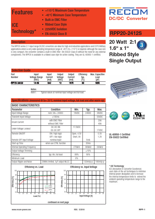
DC/DC Conver ter Specifications (measured @ ta= 25°C, nominal input voltage, full load and after warm-up)E224736UL-60950-1 CertifiedEN-55022 Certified20 Watt 2:11.6“ x 1“Ribbed StyleSingle OutputSelection GuidePart Input Input Output Output Efficiency Max. CapacitiveNumber VoltageRange Current Voltage Current typ. Load[VDC] [mA] [VDC] [mA] [%] [µF]RPP20-2412S 18-36 940 12 1670 90 1000DescriptionThe RPP20 series 2:1 input range DC/DC converters are ideal for high end industrial applications and COTS Militaryapplications where a very wide operating temperature range of -45°C to +115°C is required. Although the case sizeis very compact, the converter contains a built-in EMC filter EN-55022 Class B without the need for any externalcomponents. The RPP20 is available in a ribbed case style for active cooling. They are UL-60950-1 certified.FeaturesICETechnology*• +115°C Maximum Case Temperature• -45°C Minimum Case Temperature• Built-in EMC Filter• Ribbed Case Style• 2250VDC Isolation• EN-55022 Class B RPP20-2412S* ICE TechnologyICE (Innovation in Converter Excellence)uses state-of-the-art techniques to minimiseinternal power dissipation and to increasethe internal temperature limits to extend theambient operating temperature range to themaximum.Notes:Note1: Typical values at nominal input voltage and full load.Only the single output converters have a trim function that allows users to adjust the output voltage from +10% to -10%, please refer to the trim table that follow for details. Adjustment to the output voltage can be used with a simple fixed resistor as shown in Figures 1 and 2. A single fixed resistor can increase or decrease the output voltage depending on its connection. Resistor should be located close to the converter. If the trim function is not used, leave the trim pin open.Trim adjustments higher than the specified range can have an adverse effect on the converter´s performance and are not recommended. E xcessive voltage differences between output voltage sense voltage, in conjunction with trim adjustment of the output voltage; can cause the OVP circuitry to activate. Thermal derating is based on maximum output current and voltage at the converter´s output pins. Use of the trim and sense function can cause output voltages to increase, thereby increasing output power beyond the converter´s specified rating. Therefore: (Vout at Pins) X (Iout) ≤ rated output power.PROTECTIONSParameterConditionValueOutput Power Protection (OPP)current limit 120% typ.Over Voltage Protection (OVP)10% load 120% typ.Over Temperature Protection (OTP)case temperature 120°C, auto-recovery Isolation Voltage I/P to O/P , at 70% RH I/P to Case, O/P to Case 2250VDC / 1 Minute 1500VDC / 1 MinuteIsolation Resistance I/P to O/P , at 70% RH100M W min.Isolation CapacitanceI/P to O/P1500pF typ.Specifications (measured @ ta= 25°C, nominal input voltage, full load and after warm-up)Notes:Note2:This Power Module is not internally fused. A input fuse must be always used. Recommended Fuse: T1.6AREGULATIONSParameterConditionValueOutput Voltage Accuracy 50% load ±1.5% max.Line Voltage Regulation low line to high line ±0.3% max.Load Voltage Regulation 10% to 100% load±0.5% max.Transient Response 25% load step change, ΔIo/Δt=2.5A/us 800µs typ.Transient Peak Deviation25% load step change, ΔIo/Δt=2.5A/us±2%Vout max.Trimming Output VoltageFigure 2. Trim connections to decrease output voltage using fixed resistorsFigure 1. Trim connections to increase output voltage using fixed resistors+V IN -V INCTRL +V OUT R TRIM UP-V OUTTRIMLOAD+V IN -V INCTRL +V OUT R TRIM DOWN-V OUTTRIMLOADTrim down resistor value (K W )Vout-1%-2%-3%-4%-5%-6%-7%-8%-9%-10%12VDC 322.2137.281.153.135.524.016.09.75.01.3Trim up resistor value (K W )Vout1%2%3%4%5%6%7%8%9%10%12VDC 238.7113.168.246.332.122.415.49.86.53.2ENVIRONMENTALParameterConditionValueRelative Humidity95%, non condensing Temperature Coefficient ±0.04% / °C max.Thermal Impedance natural convection, mounting at FR4(254x254mm) PCB vertical horizontal7.2°C/W 7.8°C/WOperating Temperature Range start up at -45°C-45°C to (see calculation)Maximum Case Temperature +115°CMTBFaccording to MIL-HDBK-217F (+50°C G.B.)according to BellCore-TR-332 (+50°C G.B.)768 x 103 hours 1572 x 103 hourscontinued on next pageDerating Graph(Ta= +25°C, natural convection, typ. Vin and vertical mounting)CalculationSpecifications (measured @ ta= 25°C, nominal input voltage, full load and after warm-up)302535404550102030405060708090100Load [%]C a s e T e m p e r a t u r e [°C ]105060708090100203040506070809010018Vin24Vin 36Vin Load [%]E f f i c i e n c y [%]R thcase-ambient = 7.2°C/W (vertical) T case = Case Temperature R thcase-ambient = 7.8°C/W (horizontal)T ambient= Environment TemperatureP dissipation = Internal lossesR thcase-ambient = T case - T ambientP IN = Input PowerP dissipationP OUT = Output Powerh = Efficiency under given Operating Conditions P dissipation = P IN - P OUT = P OUTapp- P OUTapp R thcase-ambient = Thermal ImpedancehPractical Example:Take the RPP20-2412S with 50% load. What is the maximum ambient operating temperature? Use converter vertical in application.Eff min = 89% @ V nom P OUT = 20WP OUTapp = 20 x 0.5 = 10W P dissipation = P OUTapp- P OUTapp R th = T casemax - T ambient --> 7.2°C/W = 115°C - T ambienthP dissipation1.24Wh = ~88% (from Eff vs Load Graph)T ambientmax = 106.1°CP dissipation = 10- 10 = 1.24W0.89Specifications (measured @ ta= 25°C, nominal input voltage, full load and after warm-up)DC/DC Conver terSpecifications (measured @ ta= 25°C, nominal input voltage, full load and after warm-up)RPP20-2412SSeriesPACKAGING INFORMATIONParameterTypeValuePackaging Dimension (LxWxH)Tube160.0 x 45.0 x 16.0mmPackaging Quantity 5pcsStorage Temperature Range-55°C to +125°CThe product information and specifications may be subject to changes even without prior written notice.The product has been designed for various applications; its suitability lies in the responsibility of each customer. The products are not authorized for use in safety-critical applications without RECOM’s explicit written consent. A safety-critical application is an application where a failure may reasonably be expected to endanger or cause loss of life, inflict bodily harm or damage property. The applicant shall indemnify and hold harmless RECOM, its affiliated companies and its representatives against any damage claims in connection with the unauthorizeduse of RECOM products in such safety-critical applications.。
多功能测试仪
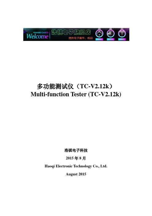
多功能测试仪(TC-V2.12k)Multi-function Tester (TC-V2.12k)浩祺电子科技2015年8月Haoqi Electronic Technology Co., Ltd.August 2015目录1综述 (3)1.1本机说明 (3)1.2功能介绍 (3)2操作指引 (4)2.1按键操作定义 (4)2.2开机 (4)2.3测试晶体管 (5)2.4自动校准 (9)2.5测试稳压二极管 (10)2.6红外解码 (10)2.7关机 (10)2.8内置锂电池电压测量 (11)2.9内置锂电池充电 (11)3性能参数 (12)4常见问题 (13)5装箱单 (13)1Overview (14)1.1Introduction (14)1.2Features (14)2Operating Instructions (15)2.1Key operational definitions (15)2.2Power on (16)2.3Detect transistor (16)2.4Selftest (20)2.5Detect Zener diode (21)2.6IR decoder (21)2.7Power off (22)2.8Built-in Li-ion Battery voltage measurement (22)2.9Charging the Battery (23)3Performance Parameters (23)4FAQ (24)5Packing List (24)多功能测试仪(TC-V2.12k)1综述1.1 本机说明① - 160x128 TFT显示屏② - 多功能按键③ - 晶体管测试区④ - 稳压二极管测试区⑤ - 红外接收窗口⑥ - Micro USB充电接口⑦ - 充电指示灯1.2 功能介绍TC-V2.12k是采用TFT图形显示的多功能测试仪。
●晶体管测试仪-自动测量NPN和PNP晶体管、N沟道和P沟道场效应管、二极管(含双二极管)、电阻(含电位器)、电感、电容、可控硅、电池(0.1-4.5V)等元器件-自动测量稳压二极管(0.01-30V)-自动校准功能●红外解码器-支持日立公司编码-红外波形显示-红外接收指示●其他-测量结果采用TFT图形显示-一键操作-自动关机(关机时长可设置)-内置大容量可充电锂电池-锂电池电压检测-支持中英文双语警告:内置锂电池,严禁将测试仪浸入水中、严禁靠近热高温源!警告:为了您的人身安全,请严格遵守锂电池使用规范和注意事项!2操作指引2.1 按键操作定义多功能按键有两种操作:●短按:按下按键不短于10毫秒且在1.5秒内松开按键●长按:按下按键1.5秒以上2.2 开机关机状态下短按多功能按键,测试仪开机并自动进行测量。
chroma-19020说明书
chroma-19020说明书
Chroma-19020系列有定电流、定电阻、定功率与定电压四种操作模式。
定电流与定电阻模式对于电压源的待测物测试,可确认待测物在不同的负载情况下,输出电压是否仍维持稳定输出。
对于电池的充电器或充电桩而言,定电压模式可以改变充电器或充电桩的输出电压,以确保充电器或充电桩在所设定的输出电压时充电电流是否正确。
另外,当待测物为电池时,电子负载则可转变为模拟电子设备拉载的行为,许多电池的放电应用、功率消耗等情况都可藉由电子负载的模拟拉载行为来进行电池的分析,而定功率模式则是模拟电子设备拉载行为的最佳选择。
致茂的chroma-19020系列电子负载也可模拟待测物短路时的情况。
直流电源或直流电源供应器的短路测试是必要的测试项目之一,chroma-19020系列电子负载以最大额定电流的拉载方式进行短路模拟,因此可用来模拟待测物的短路保护功能是否有正常动作。
F200说明书
安装指南
型号:F200
neidnl [选取日期]
炥莱茵科技有限公司
目录
炥莱茵科技有限公司
一、产品概述及功能简介 ......................................................................................................................2 二、技术指标.........................................................................................................................................3 三﹑包装清单.........................................................................................................................................3
1902GHD说明书
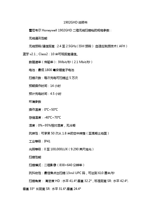
1902GHD说明书
霍尼韦尔Honeywell 1902GHD二维无线扫描枪的规格参数:
无线通讯性能
无线频段/通信距离:2.4至2.5GHz(ISM频段)自适应跳频技术(AFH)蓝牙v2.1;Class2:10米可视距离通信。
数据速率(传输率):3Mbit/秒(2.1 Mbit/秒)
电池:最低1800毫安锂离子电池
扫描次数:每次充电可扫描近5万次
预期操作时间:14小时
预计充电时间:4.5小时
环境参数
操作温度:0℃~50℃
存储温度:-40℃~70℃
湿度:0%~95%相对湿度,无冷凝
抗摔性:可承受50次从1.8米的空中摔落(至混凝土地面)
工业等级:IP41
光照等级:0至100,000LUX(9.290英尺烛光)
扫描性能
扫描模式:二维影像(838×640分辨率)
抗抖动性:最佳焦点出扫描13mil UPC码,可达到610厘米/秒
扫描角度:高密度HD:水平41.4°,垂直32.2°;标准距离SR: 水平42.4°,垂直33°长距离SR: 水平31.6°,垂直24.4°
聚焦点:130mm
可识别的反射对比度:最低20%的反射差
斜度,偏度:45°,65°
解码能力:可读取标准一维、堆叠、二维条码和邮政码以及特定的OCR字符字体。
安柏AT9210B AT9220B交流耐压测试仪用户手册说明书
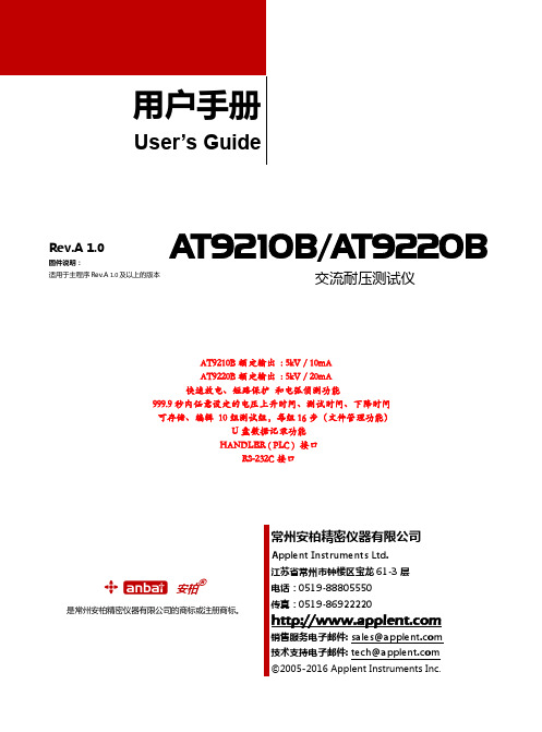
Rev.A 1.0固件说明:适用于主程序Rev.A 1.0及以上的版本AT9210B/AT9220B交流耐压测试仪AT9210B额定输出: 5kV / 10mAAT9220B额定输出: 5kV / 20mA快速放电、短路保护和电弧侦测功能999.9秒内任意设定的电压上升时间、测试时间、下降时间可存储、编辑10组测试组,每组16步(文件管理功能)U盘数据记录功能HANDLER ( PLC ) 接口RS-232C接口& % 安柏®是常州安柏精密仪器有限公司的商标或注册商标。
安全须知当你发现有以下不正常情形发生,请立即终止操作并断开电源线。
立刻与安柏科技销售部联系维修。
否则将会引起火灾或对操作者有潜在的触电危险。
●仪器操作异常。
●操作中仪器产生反常噪音、异味、烟或闪光。
●操作过程中,仪器产生高温或电击。
●电源线、电源开关或电源插座损坏。
●杂质或液体流入仪器。
安全信息为避免可能的电击和人身安全,请遵循以下指南进行操作。
免责声明用户在开始使用仪器前请仔细阅读以下安全信息,对于用户由于未遵守下列条款而造成的人身安全和财产损失,安柏科技将不承担任何责任。
仪器接地为防止电击危险,请连接好电源地线。
不可在爆炸性气体环境使用仪器不可在易燃易爆气体、蒸汽或多灰尘的环境下使用仪器。
在此类环境使用任何电子设备,都是对人身安全的冒险。
不可打开仪器外壳非专业维护人员不可打开仪器外壳,以试图维修仪器。
仪器在关机后一段时间内仍存在未释放干净的电荷,这可能对人身造成电击危险。
不可在有强烈磁场或者电场的地方使用该仪器,电磁脉冲会引起仪器故障产生火灾。
在强烈磁场环境使用该仪器不要如果在本仪器的附近使用这些设备,被测件失效击穿产生的噪声也许会影响这些设备。
在敏感的测试设备和超过3kV的测试电压,测试线间的电场会电离空气产生电晕,在测试线之间产生大量接受设备附近使用该仪器的射频带宽的干扰。
为了减少这种影响,确保测试线之间的距离足够远。
19073耐压测试器说明书

版本修订纪录
下面列示本手册于每次版本修订时新增、删减及更新的章节。
日期
版本 修订之章节
2003 年 1 月 1.0 完成本手册
2003 年 4 月 1.1 更新 ”产品规格 (18C 28C RH 70%)” “标准配件” “后背板功能说明” “RS-485 界面” “解决困难”
2003 年 12 月 1.2
请检视产品上之环保回收标示以对应下列之<有毒有害物质或元素表>。
:请对应<表一>
<表一>
:请对应<表二>
有毒有害物质或元素
部件名称
铅
汞
镉
六价铬 多溴联苯 多溴联苯醚
Pb
Hg
Cd
Cr6+
PBB
PBDE
PCBA
O
O
O
O
O
O
机壳
O
O
O
O
O
O
标准配件
O
O
O
O
O
O
包装材料
O
O
O
O
O
O
O: 表示该有毒有害物质在该部件所有均质材料中的含量在 SJ/T 11363-2006 与 EU
- “遥控控制”一节中的图 2-4。 - “时序图”一节中 ”时间 T2” 的说明。
2012 年 12 月 2.7 更新“直流耐压电流 (DCA) 校正 (DC/IR MODE)”一节中第(2)项的 图。
iv
<表二>
有毒有害物质或元素
部件名称
铅
汞
镉
六价铬 多溴联苯 多溴联苯醚
Pb
Hg
Cd
Cr6+
耐压测试器 Model 19050 series
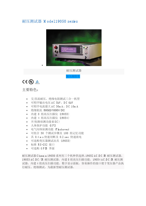
耐压测试器Model 19050 series
∙
耐压测试器
加入询价车
主要特色:
∙交/直流耐压、绝缘电阻测试三合一机型
∙可程序输出电压AC 5kV,DC 6kV
∙可程序电流最大AC 30mA,DC 10mA
∙绝缘阻抗50GΩ/1000V DC
∙内建8 组高压扫描仪(19053)
∙内建4 组高压扫描仪(19054)
∙开/短路侦测功能(OSC)
∙人体保护功能(GFI)
∙电气闪络侦测功能(Flashover)
∙可组合50 个测试步骤及100 组记忆功能
∙具0.4 ms快速切断及0.2 sec 快速放电
∙可选购变压器测试治具(19053)
∙标准RS-232 接口
∙可选购GPIB 界面
耐压测试器Chroma 19050系列有三个机种供选择,19052 AC/DC/IR耐压测试器,19053 AC/DC/ IR耐压测试器,内建8组高压扫描功能,19054 AC/DC/IR耐压测试器,内建4组高压扫描功能。
数字显示面板,容易操作的接口便于变压器产品执行耐压、绝缘测试,为最新型耐压测试器。
PTS-100 PTS-100F高压DC验证器产品说明书

PN 90-405
PN 88-150
PN 88-113 * included
HIGH VOLTAGE, INC. 31 County Route 7A • Copake, NY 12516 • f. 518.329.3271 • p. 518.329.3275
PN 32-0395 (Control Section)
PTS-100
PTS-100F
0 - 100 kV DC, 10 mA
Model
Input
Output Duty Voltmeter Current Meter
Megohmmeter Size & Weight (W x D x H) Output Termination
Scope of Supply
The PTS-100 and PTS-100F are combination high voltage DC proof tester and megohmmeter. Dielectric strength and insulation resistance testing are combined into one instrument saving time, money, size and weight. Equipped with a 5-range current meter scaled 0 - 1 dc microamps for accurate current measurement down to a 10 nanoamp resolution in the x1 range. Using the alternate scale on the current meter allows the PTS Series to double as a Megohmmeter up to 10 teraohms, scaled 100-1 megohms, insulation resistance can be taken at any voltage. An accurate 2 range voltmeter rounds out the standard instrumentation. Additional features include ruggedized anti-static and transit protected meters, rugged two piece design with foam padded handles, full-wave bridge rectifier, internal shorting solenoid with discharge resistors, and is CE marked. For other voltage options, please see the rest of our PTS Series which range from 15kV to 600kV DC. See our DBT Series for bench-top options.
- 1、下载文档前请自行甄别文档内容的完整性,平台不提供额外的编辑、内容补充、找答案等附加服务。
- 2、"仅部分预览"的文档,不可在线预览部分如存在完整性等问题,可反馈申请退款(可完整预览的文档不适用该条件!)。
- 3、如文档侵犯您的权益,请联系客服反馈,我们会尽快为您处理(人工客服工作时间:9:00-18:30)。
多通道同步耐压测试器Model 19020 series
∙
多通道同步耐压测试器
加入询价车型录下载
主要特色:
∙十组通道在一台设备
∙十组同步输出与量测
∙AC/DC/IR三合一安规
∙10台主/从机控制
∙可程序电压输出及限制值
∙开/短路侦测功能(OSC)
∙电气闪络侦测功能(Flashover)
∙可程序输出电压AC 5kV,DC 6kV
∙绝缘阻抗1MΩ ~ 50GΩ
∙标准RS232/Handler接口
∙可选购GPIB界面
∙大型LCD显示面板
∙面板锁定功能
∙轻松操作输入接口
∙CE认证
∙高效率耐压测试解决方案
高效率耐压测试解决方案
耐压测试是电气安规测试中最主要的项目之一,所有的电气组件及产品,包含变压器、电容、电源供应器、充电器、家电产品等,皆需要进行耐压测试。
Chroma团队结合20年以上开发经验,针对耐压测试开发全新架构的19020多信道扫描耐压测试器。
可同时量测所有通道的耐压漏电流值,最高可让您同时对100个待测物进行测试。
Chroma 19020让您不须购买多台耐压测试器,减少产线50%的空间浪费,单次多通道测试,提升电气安规测试的效率,对于产在线只需要做耐压测试的产品,可增进产线效能,减少测试风险。
Chroma 19020同样具有电气闪络(Flashover) 侦测功能以及开短路侦测(OSC)强大功能。
产品包含多项国际专利,是您在电气安规耐压测试上最佳的利器,不但拥有可靠的质量,更能创造高效率的测试平台。
世界首创同步耐压测试(专利)
Chroma 19020具有世界首创的同步耐压测试功能,单机可同时10组通道同步输出及量测,最大可连接10台单机控制(Master & Slave)共100组通道。
也可进行分组输出,除了避免相邻测试的压差产生,更可增进产线效率。
产品应用
Chroma 19020可应用各种电气产品,包含品保抽样检验测试、产线测试等耗时的测试。
