2.Highswitch 安装步骤
NS安装方法
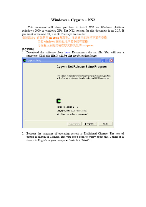
Windows + Cygwin + NS2This document will show you how to install NS2 on Windows platform (windows 2000 or windows XP). The NS2 version for this document is ns-2.27. If you want to use ns-2.28, it is ok. The steps are similar.安装准备:首先解压ns-setup压缩包,注意解压的路径不要有空格当前windows登陆的用户名不能有空格运行解压后的安装程序文件夹里的setup.exe[Cygwin]1.Download the software from here. Decompress the rar file. You will see asetup.exe. Click this file. It will be like the following figure.2.Because the language of operating system is Traditional Chinese. The text ofbutton is shown in Chinese. But you don’t need to worry about this. I think it is shown in English in your computer. Just click “Next”.3.Then choose “Install from Local Directory”4.Click “Next”.(Just keep the settings as they are.)注意:这里的Root Directory必须填“C:\cygwin”(不包括“”号)5.Click “Next”6.Click “Browse” to choose where the software is. (Please choose“ftp%3a%2f%.tw%2fWindows%2fcygwin” )(这个文件夹在解压后的安装程序文件夹里有)7.Click “OK”.8.Click “Next” and you will see the figure sh own as follows. In this window, thecygwin setup program let you choose what software you want to install.9.Click “View” first to make the word “Category “change to “Full”.在上面的对话框的Package栏里找到下面用红色字体标记出来的包,在包对应的New栏位置单击鼠标,保证选择的不是Skip,而是类似于4.3.0-1这样的版本号10.XFree86-base, XFree86-bin, XFree86-prog, XFree86-lib, XFree86-etc,make, patch, perl, gcc, gcc-g++, gawk, gnuplot, tar and gzip must be chosen.For example, if I want to install XFree-86 base (upper figure), click the “Skip” of “New” column. The “Skip” w ill be changed to “4.3.0-1” (lower figure).11.Click “Next”.(Please be patient. It may take a long time to finish the installation.)等待……12.When setup is done, it will be shown as following figure. Click “Finish”.13.Click “OK” to finish the cygwin setup program.[NS2 setup]1.Click the icon on the desktop.2.For the first time execution, it will generate some environment parameter settingfiles. In this example, smallko is my login name to windows system. Therefore, the cygwin will create a folder named “smallko” under home directory. (The actual path for smallko folder is: c:\cygwin\home\smallko) It should be noticed that the login name can not have any space in your name. For example, “A B”may cause errors when you install NS2. (smallko-hpds is my computer name)3.Please copy ns-allinone-2.27.tar.gz(这个文件在解压后的安装程序文件夹里)into your director. In this example, I copy this file to c:\cygwin\home\smallko (smallko为当前Windows的登陆用户名,不同的电脑不同). Then decompress the compressed file. Use the command “tar xvfz ns-allinone-2.27.tar.gz”.4.When the decompression is finished, it will be shown as follows.5.Begin to install ns-allinone-2.27. Change path to the ns-allinone-2.27 by typing“cd ns-allinone-2.27”. Then type “./install”.6.Please type “y” to continue.7.When it is finished, it is shown as follows.8.But before you start running NS2 simulation, you should set the path first. I haveprepared one file for it. Just copy the “.bashrc” to replace the one under your home directory. (In this example, I copy .bashrc to c:\cygwin\home\smallko)具体步骤:在解压后的安装程序文件夹目录下找到.bashrc文件,用写字板打开,找到:export NS_HOME=/home/Administrator/ns-allinone-2.27这一行,将中间的Administrator改为当前windows登陆的用户名,比如说当前登陆的用户名为AimaT,就改为export NS_HOME=/home/AimaT/ns-allinone-2.27然后保存关闭,将修改过的.bashrc文件复制到:C:\cygwin\home\Administrator\(Administrator同样为当前的windows的登陆用户名)下代替已有的.bashrc文件[Testing]1.To initial graphical mode. ( type “startxwin.bat”)2.Run the example tcl script. (Change to~/ns-allinone-2.27/ns-2.27/ns-tutorial/examples. Then run the command“ns example2.tcl”)3. If you can see the following figures, congratulations. You have successfully install cygwin + ns-2.27 under windows platform.Last modified: 2005/06/24Author : Chih-Heng, KeWebsite: http://140.116.72.80/~smallkoEmail: smallko@.twPhd candidate, EE Department, NCKU, Taiwan。
NS2安装与使用
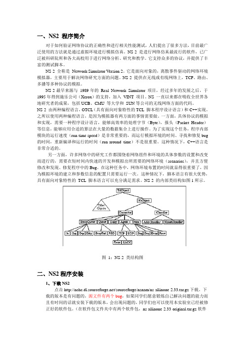
一、NS2 程序简介对于如何验证网络协议的正确性和进行相关性能测试,人们提出了很多方法,目前最广泛使用的方法就是通过虚拟环境进行模拟仿真。
NS-2 是进行网络仿真最流行的软件,已广泛被科研院所和各大高校用于进行网络分析、研究和教学。
它支持众多的协议,并提供了丰富的测试脚本。
NS-2 全称是Network Simulator Version 2。
它是面向对象的,离散事件驱动的网络环境模拟器,主要用于解决网络研究方面的问题。
NS-2 提供在无线或有线网络上,TCP、路由、多播等多种协议的模拟。
NS-2最早来源与1989年的Real Network Simulator 项目,经过多年的发展之后,于1995年得到施乐公司(Xerox)的支持,加入VINT 项目。
NS 一直以来都在吸收全世界各地研究者的成果,包括UCB、CMU 等大学和SUN等公司的无线网络方面的代码。
NS-2 由两种编程语言,OTCL(具有面向对象特性的TCL 脚本程序设计语言)和C++实现。
之所以使用两种编程语言,是因为模拟器有两方面的事情需要做。
一方面,具体协议的模拟和实现,需要一种程序设计语言,能够高效率的处理字节(Byte),报头(Packet Header)等信息,能够应用合适的算法在大量的数据集合上进行操作。
为了实现这个任务,程序内部模块的运行速度(run-time speed)是非常重要的,而运行模拟环境的时间、寻找和修复bug 的时间,重新编译和运行的时间(run-around time)不是很重要。
这种情况下,C++语言是非常合适的。
另一方面,许多网络中的研究工作都围绕着网络组件和环境的具体参数的设置和改变而进行的,需要在短时间内快速的开发和模拟出所需要的网络环境(scenarios),并且方便修改和发现、修复程序中的Bug。
在这种任务中,网络环境布置的时间就显得很重要了,因为模拟环境的建立和参数信息的配置只需要运行一次。
switch黑商店安装方法

switch黑商店安装方法Switch黑商店安装方法。
Switch黑商店是一款非常受欢迎的游戏安装工具,它可以让玩家在任天堂Switch主机上安装未经官方认可的游戏,为玩家提供更多的游戏选择。
下面我们将介绍Switch黑商店的安装方法,帮助大家轻松地使用这款工具。
首先,你需要准备一台已破解的Switch主机,如果你的Switch主机还没有进行破解,请先进行破解操作。
接下来,你需要下载Switch黑商店的安装文件,可以在互联网上搜索并下载最新版本的Switch黑商店安装文件。
下载完成后,将安装文件解压缩到你的电脑上。
然后,你需要准备一根Micro SD卡,将Micro SD卡插入电脑,并将Switch黑商店的安装文件复制到Micro SD卡的根目录下。
接着,将Micro SD卡插入已破解的Switch主机中,打开主机并进入系统设置,在系统设置中找到“主机”选项,然后选择“主机”中的“主机信息”,在“主机信息”中找到“系统版本”,确认你的Switch主机的系统版本号。
接下来,你需要根据你Switch主机的系统版本号选择合适的安装方法。
如果你的Switch主机的系统版本号在3.0.0以下,你可以使用短接方法来安装Switch黑商店;如果你的Switch主机的系统版本号在3.0.0以上但低于4.0.0,你可以使用浏览器注入方法来安装Switch黑商店;如果你的Switch主机的系统版本号在4.0.0以上但低于7.0.0,你可以使用NS-Atmosphere自制系统来安装Switch黑商店;如果你的Switch主机的系统版本号在7.0.0以上但低于9.0.0,你可以使用SX OS自制系统来安装Switch黑商店;如果你的Switch主机的系统版本号在9.0.0以上但低于11.0.0,你可以使用Atmosphere自制系统来安装Switch黑商店。
最后,根据你选择的安装方法,按照相应的教程进行操作,完成Switch黑商店的安装。
NETGEAR GS308 Gigabit Ethernet Switch 第二阶段安装指南说明书
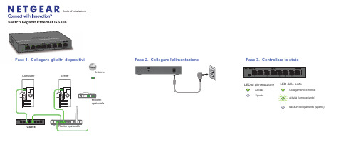
Switch Gigabit Ethernet GS308Fase 2. Collegare l'alimentazione Fase 3. Controllare lo statoModemopzionaleFase 1. Collegare gli altri dispositivi GS308InternetAcceso SpentoLED di alimentazioneLED delle porteAttività (lampeggiante)Nessun collegamento (spento)Collegamento Ethernet Fase 1. Collegare gli altri dispositivGuida all'installazioneComputerServerRouter opzionaleOttobre 2012NETGEAR, il logo NETGEAR e Connect with Innovation sono marchi commerciali e/o marchi registrati diNETGEAR, Inc. e/o delle sue consociate negli Stati Uniti e/o in altri Paesi. Le informazioni sono soggette amodifica senza preavviso. Altri nomi di prodotti e marche sono marchi registrati o marchi commerciali deirispettivi proprietari. © NETGEAR, Inc. Tutti i diritti riservati.Per conoscere la dichiarazione di conformità UE completa, visitare la pagina/app/answers/detail/a_id/11621/.Dichiarazione di condizioni: nell'interesse di migliorarne il design interno, la funzionalità operativa e/ol'affidabilità, NETGEAR si riserva il diritto di apportare modifiche ai prodotti descritti nel presente documentosenza alcun preavviso. NETGEAR declina ogni responsabilità durante l'utilizzo o l'applicazione dei prodotti odegli schemi circuitali qui descritti.Caratteristiche tecnicheCaratteristica DescrizioneInterfaccia di rete Connettore RJ-45 per 10BASE-T, 100BASE-TX o1000BASE-TCavo di rete Categoria 5e (Cat 5e) o cavo Ethernet superiore Porte8Alimentatore Ingresso c.c. a 12V @ 1,0AConsumo energetico3,8W max.Peso0,4 KgDimensioni (larg. x prof. x alt.)158 mm x 102 mm x 26 mm 6,22". x 4,02". x 1,02".Temperaturaoperativa0–40° CUmidità operativa Umidità relativa 10%–90%, senza formazione di condensaConformitàelettromagneticaCE Classe BApprovazioni enti per la sicurezza Marchio CE, CBAssistenza tecnicaUna volta completata l'installazione del dispositivo, individuare il numero di serieriportato sull'etichetta del prodotto e utilizzarlo per registrare il prodotto all'indirizzohttps://.NETGEAR consiglia di consultare solo risorse di assistenza ufficiali NETGEAR.La registrazione del prodotto è necessaria per poter utilizzare il servizio diassistenza telefonica di NETGEAR. NETGEAR consiglia di registrare il prodotto dalsito Web di NETGEAR. Gli aggiornamenti del prodotto e l'assistenza Web sonodisponibili alla pagina .Pensato unicamente per l'uso in interni e per tutti gli stati membri dell'UE, gli statiEFTA e la Svizzera.。
网抵Managed Switch PSU安装指南说明书
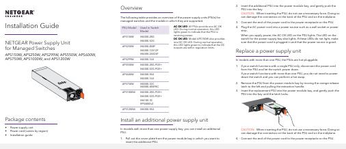
Installation Guide OverviewThe following table provides an overview of the power supply units (PSUs) for managed switches and the models in which they are supported.PSU Model Used in SwitchModelAPS150W M4300-28GM4300-52GAPS250W M4300-8X8FM4300-12X12FM4300-24X24FAPS299W M4300-16XAPS550W M4300-28G-POE+M4300-52G-POE+APS600W M4300-96XM4300-16XAPS750W M4500-32CM4500-48XF8CAPS1000W M4300-28G-POE+M4300-52G-POE+M6100-3SRPS4000v2APS1200W M4300-96XInstall an additional power supply unitIn models with more than one power supply bay, you can install an additional PSU.1. Pull out the cover plate from the power module bay in which you want toinsert the additional PSU.AC OK LED. All PSUs provide one AC OKLED. During normal operation, this LEDlights green to indicate that the PSU isreceiving power.DC OK LED. Model APS150W also providesone DC OK LED. During normal operation,this LED lights green to indicate that the DCoutputs are within regulation limits.NETGEAR Power Supply Unitfor Managed SwitchesAPS150W, APS250W, APS299W, APS550W, APS600W,APS750W, APS1000W, and APS1200WPackage contents• Power supply unit• Power cord (varies by region)• Installation guide 2. Insert the additional PSU into the power module bay, and gently push thePSU into the bay.CAUTION: When inserting the PSU, do not use unnecessary force. Doing so can damage the connectors on the back of the PSU and on the midplane.3. Connect the end of the power cord to the power receptacle on the PSU.4. Plug the AC power cord into a power source such as a wall socket or powerstrip.When you apply power, the AC OK LED on the PSU lights. The LED on the switch for the power supply bay also lights. If these LEDs do not light, make sure that the power cord is plugged in and that the power source is good.Replace a power supply unitIn models with more than one PSU, the PSUs are hot-pluggable.1. If your switch functions with a single PSU only, disconnect the power cordfrom the PSU and let the switch power down.If your switch functions with more than one PSU, you do not need to power down the switch and you can perform a hot swap.2. Remove the PSU from the power module bay by moving the orange releaselatch to the left and pulling the extraction handle.3. Insert the replacement PSU into the power module bay, and gently push thePSU into the bay until the latch locks.CAUTION: When inserting the PSU, do not use unnecessary force. Doing so can damage the connectors on the back of the PSU and on the midplane. 4.Connect the end of the power cord to the power receptacle on the PSU.NETGEAR, Inc.350 East Plumeria DriveSan Jose, CA 95134, USANETGEAR INTERNATIONAL LTD Floor 1, Building 3University Technology Centre Curraheen Road, Cork, T12EF21, Ireland© NETGEAR, Inc., NETGEAR and the NETGEAR Logo are trademarks of NETGEAR, Inc. Any non‑NETGEAR trademarks are used for reference purposes only.November 20195. Plug the AC power cord into a power source such as a wall socket or powerstrip.When you apply power, the AC OK LED on the PSU lights. The LED on the switch for the power supply bay also lights. If these LEDs do not light, make sure that the power cord is plugged in correctly and that the power source is good.Technical specificationsSpecificationsPSUAC input• APS150W . 100–127VAC, 3A, 50–60 Hz or 200–240VAC, 1.5A, 50–60 Hz • APS250W . 100–240VAC, 3.5–2A, 50–60 Hz • APS299W . 100–240VAC, 5–2.5A, 50–60 Hz • APS550W . 100–240VAC, 9–4A, 50–60 Hz • APS600W . 90–132VAC, 8A, 47–63 Hz or 180–264VAC, 4A, 47–63 Hz • APS750W . 100–240VAC, 10/5.36A max, 50–60 Hz • APS1000W . 100–127VAC, 9.9A, 50–60 Hz or 200–240VAC, 7.8A, 50–60 Hz • APS1200W . 90–132VAC, 15A, 43–67 Hz or 180–264VAC, 8A, 43–67 HzDC output • APS150W . +12V, 12.5A• APS250W . +12V, 20A or +12 VSB 1A • APS299W . +54.5V, 5.51A• APS550W . +54V, 10.95A or +12 VSB 2.08A • APS600W . +54.5 VDC, 11A• APS750W . +12V, 61.5A or +12VSB 3A• APS1000W . 56V, 12.12A or +12 VSB 1.8A (@ 100–127VAC) 56V, 17.35A or +12 VSB 2.4A (@ 200–240VAC)• APS1200W . +54.5 VDC, 22A @ 230 VAC, or 18.35A @ 115 VACSpecificationsPSUDimensions (H x W x D)• APS150W . 1.5 x 2.0 x 7.3 in. (39 x 50.5 x 185 mm)• APS250W . 1.5 x 2.9 x 7.3 in. (39 x 74 x 185 mm)• APS299W . 1.5 x 2.9 x 7.6 in. (39 x 74 x 194 mm)• APS550W, APS1000W . 1.6 x 3.6 x 8.7 in. (40 x 87 x 208 mm)• APS600W, APS1200W . 1.6 x 2.9 x 7.3 in. (40 x 73 x 185 mm)• APS750W . 1.6 x 7.5 x 8.1 in. (40 x 192 x 206 mm)Operating temperature• APS250W . 32 to 122ºF (0 to 50ºC)• APS150W, APS299W, APS550W, APS600W, APS1000W , APS1200W . 23 to 122ºF (–5 to 50ºC)• APS750W . 32 to 131ºF (0 to 55ºC)Operating relative humidity• APS150W . Up to 95% noncondensing• APS250W, APS299W, APS550W, APS600W, APS1000W, APS1200W . 5% to 95% noncondensing • APS750W . 10 to 90% noncondensingOperating altitude level • APS250W, APS550W, APS1000W . Up to 9,800 feet (3,000 m) above sea level • APS150W , APS299W, APS600W, APS750W, APS1200W . Up to 16,000 feet (5,000 m) above sea levelStorage temperature• APS150W, APS250W, APS299W . –40 to 158ºF (–40 to 70ºC)• APS550W, APS600W, APS1000, APS1200W . –40 to 185ºF (–40 to 85ºC )Storagealtitude level Below 49,000 feet (15,000 m) above sea levelMTBFAll models except APS750W . 4,534,733 hrs (~517 years) @ 77ºF (25ºC)APS750W only . 200,000 hrs (~23 years) @ 122ºF (50ºC)SupportThank you for purchasing this NETGEAR product. You can visithttps:///support/ to register your product, get help, access the latest downloads and user manuals, and join our community. We recommend that you use only official NETGEAR support resources.Si ce produit est vendu au Canada, vous pouvez accéder à ce document en français canadien à https:///support/download/.(If this product is sold in Canada, you can access this document in Canadian French at https:///support/download/.)For regulatory compliance information including the EU Declaration of Conformity, visit https:///about/regulatory/.See the regulatory compliance document before connecting the power supply.Do not use this device outdoors. If you connect cables or devices that are outdoors to this device, see https:///000057103 for safety and warranty plianceSafetyIEC 60950-1, EN 60950-1, CB Certificate/Report, UL/CSA 60950-1CE Low Voltage Directive 2006/95/EC (Europe)CCC (China)KC (Korea)EMCCC / ICES-003 Emission (USA/Canada)CRISP 22 Emission (International)EN55022 Emission (Europe)EN55024 Immunity (Europe)EN61000-4-2 Electrostatic Discharge EN61000-4-3 Radiated RFI Immunity EN61000-4-4 Electrical Fast Transients level 4EN61000-4-5 Electrical Surge LevelEN61000-4-6 RF ConductedEN61000-4-8 Power Frequency Magnetic Fields EN61000-4-11 Voltage Dips and Interruptions EN61000-4-8 Power Frequency Magnetic Fields EN61000-4-11 Voltage Dips and Interruptions EN61000-3-2 Harmonics (Europe)EN61000-3-3 Voltage Flicker (Europe)。
Windows下NS的详细安装过程

封面作者:Pan Hongliang仅供个人学习Windows下NS2的详细安装过程[通信网络]发布时间:2009-07-02 16:07:53简单的说,NS-2是一个网络模拟器,所以经常被用到网络课的教学中。
NS-2是OpenSource的,最早的版本是在linux/unix下运行的,后来有了windows下用vc编译运行的版本,但从2.26以后就放弃了对vc的支持,所以现在装NS2只有两条路,要么装个linux,要么就在wind ows下装个cygwin,然后再在cygwin上装ns2.为了一个ns2(完成安装后不过100M)而安装linux(RH9完全安装大概在5G左右)实在不值,所以我决定用cygwin先去/setup.exe下载setup.exe,运行,得到这个界面:点下一步,出现这个界面:选择“Install from Internet”,当然,如果本地已经下载了你所需要的package,也可以选“Install from Lo c al Directory”接下来选择安装位置:可以自己选择一个目录安装。
现在(10/13/05)的cygwin版本跟NTFS完全兼容,所以不用担心,可以放心的把它装在NTFS分区。
至于Test File Type,建议最好设成unix,虽然我没试过用dos格式,但是鉴于OpenSource的软件原本都是linux/unix下的,所以最好还是用unix继续下一步选择一个保存package的地方,我们要用到的package大小大概是60M。
当然,如果选择的是Install Fr om Local Directory,那么这一步就会变成“指定package所在的位置”下一步指定代理服务器。
教育网内的机器是没办法直接上国外网的,所以要指定代理。
最该死的是它的mirror li st放在国外,所以即使你知道一个国内的ftp地址(可以下载package的地址,比如ftp:///c ygwin),你也得指定代理服务器,要不然你就没办法获得mirror list,安装就进行不下去。
sw安装教程
sw安装教程
要安装SW软件,你可以根据以下步骤进行操作:
1. 首先,确保你拥有有效的安装文件。
通常,你可以从SW官方网站或其他可信的软件下载网站下载安装程序。
2. 打开下载的安装文件。
你可能需要双击该文件或选择“运行”
选项,以启动安装程序。
3. 安装程序将会展示一系列的安装选项和设置。
仔细阅读每个选项,并根据你的需求进行选择。
通常,你可以选择安装路径、语言设置、附加组件等。
4. 一旦你完成了所有的安装选项,点击“下一步”或“安装”按钮,开始安装过程。
5. 安装程序将会开始复制文件,并在系统中进行必要的配置。
这个过程可能需要一些时间,请耐心等待,不要中断安装过程。
6. 安装完成后,你可以选择启动SW软件。
根据你的系统,
SW可能会在桌面上创建一个快捷方式,你可以通过它来快速
启动软件。
7. 第一次启动软件时,你可能会被要求输入产品密钥或注册信息。
根据你的授权情况,输入相应的信息并完成注册过程。
8. 一旦注册完成,你就可以开始使用SW软件了。
探索软件功
能,参考帮助文档或教程来学习使用SW的各种工具和功能。
希望这些步骤能够帮助你成功地安装SW软件。
如果你遇到任何问题,可以参考SW官方网站上的安装指南或寻求技术支持。
Honda GL1800D DA CB Switch 安装指南说明书

PARTS LISTNo.DescriptionQty (1)Installation Instructions URL 1(2)CB switch1(3)Master cylinder holder 1(4) 6 mm socket bolt 2(5) 4 mm screw 1(6) 5 mm screw 1(7)Collar 1(8)Wire tie 3(9)Holder clip1radiator, etc., to cool before installing the accessory.NOTE:• Disconnect the negative (-) cable from the battery before installing this accessory.• The memory of the clock will be erased when you disconnect the battery. Reset the clock after reconnecting the battery.• Reinstall the removed parts on the motorcycle and make sure that the wires and harnesses are not pinched.• Trim the excess ends off the wire ties after attaching them to the wire harnesses. Do not allow the cut part of the wire tie to interfere with another harness or brake hose.• For installation of CB radio and CB passenger switch, refer to the Installation Instructions for each accessory.1. Open the left saddlebag lid as shown.• Repeat on the right side.TOOLS REQUIREDPhillips ® screwdriver Hex wrench (5 mm)Side cutters Torque wrenchItemN·m kgf·m Ibf·ft 4 mm screw 10.10.75 mm screw 4.20.4 3.16 mm socket bolt121.29TORQUE CHARTTighten all screws, bolts, and nuts to their specified torque values. Refer to the Service Manual for the torque values of the removed parts.18. Remove the clip and disconnect the connector asshown.19. Remove the right outer air guide as shown.20. Remove the pocket cable as shown.17. Remove the connector as shown.<Right side>2-PIN WATERPROOF CONNECTOR (Black)CLIP2-PIN WATERPROOF CONNECTOR (Black)SCREWCLIPRIGHT OUTER AIR GUIDEPOCKET CABLESCREW16. Remove the parts as shown.• Repeat on the right side.<Left side>SCREWSCREWCOLLARSCREW (Save)REAR COVER(Save)FRONT COVER(Save)31. Remove the front and rear cover as shown.32.Remove the screw as shown.33.Remove the CB switch case as shown.35. Install the CB switch case as shown.42. Secure the CB switch harness with the holder clip asshown.43. Route the CB switch harness as shown.CB SWITCH HARNESSCB SWITCH HARNESSCB SWITCH HARNESSHOLDER CLIP Secure the CBswitch harness to the motorcycle’s harness.MOTORCYCLE’S HARNESS44. Secure the CB switch harness with the wire tie.MOTORCYCLE’S CLAMPCB SWITCHHARNESS’S WIRE TIE Secure the CBswitch harness to the motorcycle’s harness.CB SWITCH HARNESSSecure the CB switch harness passing under the motorcycle’s harness.45. Install the motorcycle’s clamp in the reverse order ofremoval.46. Install the bolt in the reverse order of removal.CLAMPCB SWITCH HARNESSCLAMP (Reuse)BOLT (Reuse)。
2-1.G4安装指南
我的文档取名为:My Documents 在D盘创建这个文件夹。
安装G4的6个重点:1.我的文档路径必须修改为英文(大多电脑默认是英文)2.安装主游戏,路径不能携带英文。
3.打补丁,激活序列号。
4.对应遥控器加密狗开关,插入电脑USB接口。
5.设置遥控器通道,自动检测。
6.再次检查和调试对应在游戏中遥控通道。
首先要做最重要的一个工作,检查我的文档目录是否存在中文,例如:D:\我的文档,或是:D:\360data\重要数据,这样都是不行的。
标准格式是:D:\My Documents1.首先将遥控器的隐藏按钮(这个隐藏按钮是个加密狗开关,在深处一厘米处,用一个尖尖的物体可以拨动。
)拨到G3.5的位置,他可以解密G4。
拨到最上面然后往下拨一档就是G3.5位置。
2.将遥控器USB接口插入电脑的新USB的接口上,并打开遥控的总开关到ON的位置。
3.复制光盘中G4文件夹下的“安装补丁(里面的文件)”到G4的安装目录根目录下,覆盖即可。
4.启动G4在桌面的RealFlight G4 launcher 快捷方式(非汉化版的那个)5.输入安装说明里面带的对应序列号。
6.启动桌面上RealFlight G4汉化版快捷方式。
7.所有摇杆和微调按钮居中,右上角银色开关开关往上打,左上角的黑色旋钮逆时针转到头,点自动检测。
8.根据提示进行操作,直至完成。
9.点尝试忽略运行有实习的错误。
10.点击运行游戏。
11.点游戏最上方的Controller 选项中的Select Controller,选1.InterLink Transmitter 6 channel (如果没看到这个带6数字的选项,则说明遥控没打开或者没有把加密狗开关拨到对应位置,代表USB驱动未能安装对应成功),请从重新检查并重新换个USB接口连接遥控器进行驱动安装。
12.为了您对遥控器各个按钮的掌握和操控,请看美国第一遥控学校的教程,他在赠送的那张DVD光盘里面,第一课就讲了详细的操作方法,让您可以把飞机飞起来。
switch怎么使用的流程是怎样的
switch怎么使用的流程是怎样的1. 准备工作在使用switch之前,需要进行一些准备工作。
具体步骤如下: - 确保你已经安装了支持switch功能的操作系统或软件。
- 检查你要使用的设备是否支持switch功能,并且已经正确连接到电源和网络。
2. 开始使用switch一旦完成准备工作,你就可以开始使用switch功能了。
下面是使用switch的流程:2.1 打开交换机首先,需要将交换机的电源打开。
通常,交换机的电源按钮位于设备的背面或侧面。
根据设备型号的不同,可能需要按住按钮几秒钟才能启动交换机。
2.2 连接设备将需要连接到交换机的设备插入交换机的端口。
可以使用网络电缆将计算机、服务器、打印机或其他网络设备连接到交换机上。
确保所有设备的电源都已打开,并且正确插入了交换机的端口。
2.3 配置交换机一旦设备连接完毕,你可能需要配置交换机以满足特定的网络需求。
配置交换机的方法因设备型号和操作系统而异,但通常可以通过以下步骤进行: - 打开一个支持switch配置的终端设备(如计算机、笔记本电脑等),通过网络电缆将其连接到交换机上。
- 打开终端设备上的命令行界面(如Windows下的命令提示符、Linux下的终端等)。
- 输入正确的命令以登录到交换机的管理界面。
这通常涉及到输入用户名和密码,以验证你的身份。
- 一旦成功登录,你就可以开始配置交换机了。
你可以设置端口速度、虚拟局域网(VLAN)、链路聚合、端口镜像等功能,以满足特定的网络需求。
具体的配置命令因设备型号而异,请参考交换机的用户手册或官方文档。
2.4 网络测试完成交换机的配置后,你可以进行一些网络测试,以确保一切正常工作。
例如,你可以尝试通过交换机传输文件,测试网络连接的速度和稳定性。
同时,你还可以进行一些更高级的网络测试,如虚拟局域网的配置和广播风暴的防范等。
3. troubleshoot如果在使用switch的过程中出现问题,你可以尝试以下方法来解决问题: - 检查物理连接:确保所有设备的电源和网络连接都已打开,并且正确连接到交换机的端口。
Netgear Smart Switch 系列快速安装指南说明书
Follow these instructions to set up your smart switch. Prepare to Install Your Smart Switch•Prepare a PC with an Ethernet adapter and a CD ROM drive.•Before proceeding with the smart switch installation, familiarize yourself with the contents of the Resource CD, especially the manuals.First, Install the Smartwizard Discovery Utility on a PC 1.Power on your PC, let the operating system boot up completely, and log in asneeded.2.Insert the Resource CD for the Smart Switch Series into your CD-ROM drive.The CD main page shown below will load.3.Click Install. Follow the links on the CD and the setup utility prompts tocomplete the installation of the Smartwizard Discovery utility.4.Click OK when done. Next, Connect Your Smart Switch in the Correct OrderNote: These instructions assume you are using DHCP in your network. If you areusing static IP addressing in your network, configure the switch IP address beforeconnecting it to your network. In the absence of a DHCP server, the switch willdefault to 192.168.0.239 for its IP address. To configure the switch beforeconnecting it to your network, set up the PC with an IP address in the 192.168.0.xsubnet, and connect the PC to the switch. Then, use the Smartwizard Discoveryutility as illustrated below to configure the switch.1.2.Power on the switch. The switch will get its TCP/IP configuration from theDHCP server on your network.3. Assure that the PC with the Smartwizard Discovery utility can a cc ess the switch.Now, Configure the Switch with the SmartwizardDiscovery Utility1.Click the SmartDiscovery icon on your desktop or in Windows Startmenu Programs to view this screen.2.Click Discover to find your switch in the network.The Smartwizard Discovery utility finds the switch and displays its MACAddress, IP Address, and model number. If you cannot configure your switch,verify that the cable connections are secure, that the IP address configuration ofthe PC is in the same subnet as the switch, and click the Discover button.3.Click to select the line displaying the details of your switch. If there are multiplesmart switches in your network, be sure to select the one you want to configure.August 2004。
ns2安装
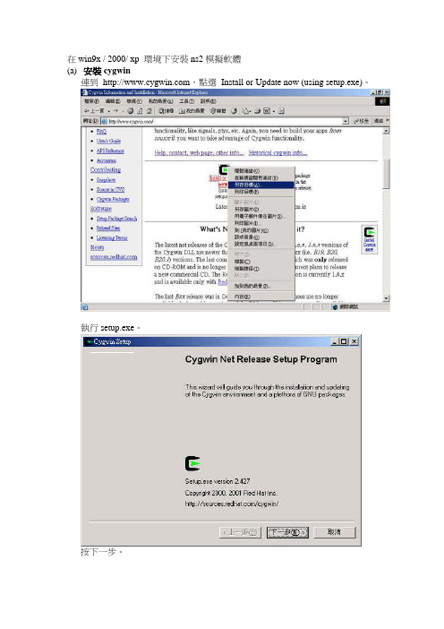
在win9x / 2000/ xp 環境下安裝ns2模擬軟體(a)安裝cygwin連到,點選Install or Update now (using setup.exe)。
執行setup.exe。
按下一步。
選擇Install from Internet,並按下一步。
在Root Directory中,可以選擇安裝的目錄,不過在這裡建議大家使用內定的路徑c:\cygwin。
其它另外兩個選項也使用內定值即可。
按下一步。
在Local Package Directory中,是讓使用者設定下載cygwin所需要檔案的目錄。
使用者可以自行更改路徑或者使用與安裝程式setup相同的路徑(內定值)。
按下一步。
選擇網際網路連線的方式。
第一種是直接連線,第二種是使用IE5的設定,第三種是使用HTTP/FTP Proxy的方式。
若使用者是學校的學生,建議採用第三種方式,可以增快下載的速度。
以筆者在成功大學下載程式,設定如下。
按下一步。
選擇下載的地點,在這裡我們選擇從交通大學的FTP站下載。
按下一步。
選擇要安裝的軟體套件。
在這邊可以先點選View,使得旁邊的Category變成Full,這樣就可以對於細部的選項做選擇。
要選擇的有XFree86-base、XFree86-bin、XFree86-prog、XFree86-lib、XFree86-etc、make、patch、perl、gcc、gcc-g++、gawk、gnuplot、tar和gzip。
以下圖為例,點選XFree86-base,可以使得狀態從new改變成4.3.0-11。
按下一步。
開始下載並安裝。
完成後,會詢問使用者是否想要產生小圖示於桌面和開始選單。
按完成以結束安裝程式。
若是還有需要安裝其它的軟體套件需要安裝,可以重新執行setup安裝即可。
(b)安裝ns2點選桌面上的cygwin小圖示。
第一次執行的時候,會根據目前電腦的使用者和電腦的名稱等資訊,在cygwin的home的目錄下產一個使用者的資料夾,並放入環境變數設定等相關檔案(.bashrc、.bashrc_profile和.inputrc)。
D-Link DGS-108 8-Port Gigabit Desktop Switch 快速安装指
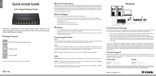
ENGLISH Quick Install Guide8-Port Gigabit Desktop SwitchThank you for purchasing the 8-Port Gigabit Desktop Switch. Follow the easy steps in this guide to properly set up your switch. Please verify that all the package contents listed below are available.Package ContentsIf any of the above items are missing, please contact your reseller.NetworkBefore You BeginThe setup of the Switch can be performed using the following steps:• Visually inspect the DC power jack and make sure that it is fully secured to the power adapter.• Do not cover the ventilation holes on the sides of the Switch, and make sure there is adequateventilation around it.• Do not place heavy objects on the switch.• Place the Switch in a cool and dry environment.Technical SupportHaving trouble installing your new product? D-Link’s website contains the latest user documentation andsoftware updates for D-Link products. U.S. and Canadian customers can contact D-Link Technical Supportthrough our website or by phone.United StatesTelephone: (877) 453-5465Internet: CanadaTelephone: (800) 361-5265Internet: http://support.dlink.caCopyright ©2011 All rights reserved. D-Link and the D-Link logo are registered trademarks of D-Link Corporation or its subsidiaries. Othertrademarks are the property of their respective owners. Product specifications, size and shape are subject to change without notice, and actualproduct appearance may differ from that depicted on the packaging. Visit (US) or dlink.ca (Canada) for more details.Version 2.0 | September 6, 2011What This Product DoesExpand your home or office network with the D-Link® 8-Port Gigabit Desktop Switch. This Switch letsyou network up to eight devices at speeds up to 2000Mbps (at full duplex) and is compact enough to beplaced virtually anywhere in your home or office. Add a computer, printer, NAS storage device, or networkcamera and expand the functionality of your network. You may also connect the Switch to hubs, switches,and routers to expand your network.DGS-108 8-Port Gigabit Desktop Switch Wall Mount KitPower AdapterD-Link Green Technology implements special power-saving features that detect cable length and linkstatus and adjust power usage accordingly. Green Technology saves energy in two specific ways:1. If there is no link on a port (when there is no connection or the device connected is turned off) theport(s) will enter a “sleep mode” which will drastically reduce the amount of power used.2. D-Link Green Technology detects the length of connected Ethernet cable and adjusts powerusage accordingly without affecting performance. This way, a port connected to a 10m or undercable only uses as much power as it needs, instead of using full power, which is only needed for100m cables.This product is IEEE 802.3az Energy Efficiency Ethernet compliant. The IEEE 802.3az EEE standard definesmechanisms and protocols intended to reduce the energy consumption of network links duringperiods of low utilization, by transitioning interfaces into a low-power state without interrupting thenetwork connection. Both connected devices must support 802.3az EEE for power saving support. If theconnected device does not support 802.3az EEE, the switch will default to D-Link’s Green Technology ofpower saving.D-Link Green TechnologyPower Indicator - This green indicator light is on when the Switch is receiving power; otherwise, it is off.Link/Act - This LED indicator light is green when the port is successfully connected to an 1000Mbpsdevice and will blink as data is transmitted or received.This LED indicator light is amber when the port is successfully connected to an 100Mbps or 10Mbpsdevice and will blink as data is transmitted or received.LEDsConnecting the SwitchStep 1Plug the supplied power adapter into the Switch and the other end into a power outlet, power strip,or surge protector (recommended). Verify the Power indicator is lit on the Switch.Step 2Connect one end of an Ethernet cable in the device you want to connect to the Switch and the otherend into one of the Ethernet ports on the Switch. Check the Link lights (LEDs) on both the Switch andthe device to verify that the cable is good and that there is a valid connection.Note: A Category 5 (or higher) Ethernet cable must be used for 100Mbps or higher operation.DGS-108• You may mount the Switch on a wall with the included mounting kit. Two mounting slots areprovided on the bottom of the Switch for this purpose.• Magnet mounting is an optional method to mounting the Switch on a wall, and is not includedwith the package contents.MountingDGS-108。
SpeedSwitch 安装及使用手册说明书
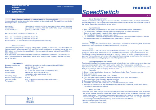
Aim of the documentationThe aim of this document is to provide the user with all the information needed in order to install and to use the SpeedSwitch. For information on connection-points in the vehicle itself, we would like to refer to the section ‘Connection-points in the vehicle’ below.Important notes- Read this manual completely before proceeding with the installation of the SpeedSwitch!- The installation of the SpeedSwitch should only be carried out by trained specialists!- Observe all modern quality standards of the automotive industry!- The SpeedSwitch should be installed in a dry place!- The SpeedSwitch meets all the requirements of Commission Directive 95/54/EC for(motor) vehiclesand electrical/electronic sub assemblies (ESA) to be fi tted to a vehicle!FunctionSwitches a 12 V (or 24 V) device on or off at a preset speed or number of revolutions (RPM). Connect to an electronic Vehicle-speedsignal or Engine-speedsignal in a vehicle.TermsThe elements found in this document are established to inform the user. They may be modifi ed without giving prior notice. Beijer Automotive BV can not be held responsible for any modifi cations made. Nor can Beijer Automotive BV be held responsible for any errors printed, or for any subsequential conse-quences. The manufacturer can not be held responsible for any damage or malfunction of any system or device, that could be caused by (improper) use of the SpeedSwitch.Connection-points in the vehicleTogether with this SpeedSwitch you receive a one-time login for the internetsite www.in-car.nl where you can view vehicle-specifi c information which can be used to fi nd the connection-points for theSpeedSwitch. The sticker that is placed at the bottom of page 2, contains the Username and Password that you need to login to the home-page of www.in-car.nl Procedure:1. Collect the right specifi cations of your car: Manufacturer, Model, Type, Production year, etc.2. Go to www.in-car.nl3. Select the English language at the top of the page.4. Fill in the codes that are printed on the sticker under the items User: and Password: . Then press Login. Note: the codes are case-sensitive!5. Choose your Manufacturer and Model and press GO.6. Choose the instruction that covers your car: it will be viewed on your screen.7. Attention: the instruction can only be viewed once! Use the button ‘Printable version’ and print the instruction for your own convenience.Before you start- The back cover of the casing is provided separately so that the connector blocks are easily accessible and visible. After the connections have been made, the cover can simply be pressed into place on the casing. If necessary, the cover can be removed subsequently with a small screwdriver or a knife blade.- Make sure that you have tightened the screws for the contacts that are not in use. This prevents them from coming loose and potentially causing short circuits on the circuit board!- Always make soldered connections!- Insulate the wires that are not used!manualSpeedSwitch020928Step 4. Connect (optional) an external switch to Connectorblock 2An external switch can be connected to the contacts of Connectorblock 2. This switch then permits the following functions to be selected:Always ON: (SpeedSwitch active, RED LED is illuminated and the relay is activated)Always OFF: (SpeedSwitch not active, RED LED is off and the relay is not activated)Automatic ON/OFF:(default SpeedSwitch function)Pin 2 is the central contact for Connectorblock 2.Pins 1 and 2 connected: SpeedSwitch always ONPins 2 and 3 connected: SpeedSwitch always OFFNo connections / no external switch: default SpeedSwitch functionality.Speed calculation:The relationship between the frequency setting and the speed is as follows: V = F/P x 3600 where V is Vehicle-speed, F is frequency and P the number of pulses per kilometre. In practice: in a car that gives 5000 pulses per kilometre, the SpeedSwitch will be activated at its lowest setting (4 Hz)at 4/5000 x 3600 = 2.88 km/h.A certain amount of hysteresis has been built into the SpeedSwitch to prevent it from switching too often. This means that the SpeedSwitch will cut out at a slightly lower frequency than the frequency set for it to cut in.Characteristics European certifi cation: e4 020928 (according to the European guideline 95/54/EC)Dimensions: L x W x H: 57 x 57 x 31 mm Weight: 72 grammsPower supply: 9 – 15 Volt (red wire) and 18-30 Volt (orange wire)Current drawn: switched on, relay activated: 60 mA rest position, relay not activated: 20 mA Frequency range:± 5 Hz – 10 kHz Maximum frequency API: 40 kHzSwitched current: Max. 10 A (built-in relay with make/break contact)Temperature-20°C / +70°Ce 41432312C o n n e c t o r b l o c k 2C o n n e c t o r b l o c k 1LED redLED greenButtonApplicationsp. 2p. 3Username and Password:www.in-car.nl1 (API)4 (NC)3 (CM)2 (NO)312off onspeedsignal12 V24 V ground><>>vehicle1 (API)4 (NC)3 (CM)2 (NO)312off onspeedsignal12 V24 V groundEPS<>vehicleNote 1The SpeedSwitch is equipped with a RED and a GREEN LED. To adjust the SpeedSwitch in a proper way, only the functioning of the GREEN LED is important. Only when optional an external switch is connected to Connectorblock 2, the functioning of the RED LED becomes important. The GREEN LED shows the program-mode and the status. The RED LED shows whether the relay is engaged.Note 2The potentiometer on the circuit board is preset by the manufacturer and does not need adjustment, unless this is advised by Beijer Automotive.Installation in 4 steps!Step 1. Determine with the examples which Relaycontact youare going to use: a Make- or Breakcontact.Step 2. Supply the SpeedSwitch with a good ground (black), aswitched ignition (red or orange) and a speed-or RPM-signal(blue).Step 3. Determine the desired switch moment with the button onthe circuit board.Step 4.Connect (optional) an external switch to Connectorblock 2.Step 1. Determine which Relaycontact (Make- or Breakcontact) you are going to use and make the specifi c connections on Connectorblock 1Pin 1 “API”: is a fi ltered and amplifi ed 1:1 output signal (e.g. speed or revs signal) with a peak value of 10 V (standard API output).Pin 2. ”NO”: Make-contact (Normally open). This is the relay contact that is not connected to the central relay contact (pin 3 “CM”) in the rest position. When the SpeedSwitch is activated (the frequency being supplied is higher than the preset frequency and the GREEN LED is illuminated), this contact is connected to the central relay contact (pin 3 “CM”).Pin 3. “CM”: Central relay-contact (Common).Pin 4. “NC”: Break-contact (Normally Closed). This is the relay contact that is connected to the central relay contact (pin 3 “CM”) in the rest position. When the SpeedSwitch is activated (the frequency being supplied is higher than the preset frequency and the GREEN LED is illuminated), this contact is interrupted from the central relay contact (pin 3 “CM”). Step 2. Supply the SpeedSwitch with the necessary input-signals Red 12Volt switched ignition (+15), or Orange: 24Volt switched ignition (+15).Black: Ground.Blue: Vehicle-speedsignal or Engine-speedsignal, at least 1,5 Volt (peak/peak) square wave or sinewave.Step 3. Determine the desired switch moment with the button on the circuit boardTo set the desired switch moment in the SpeedSwitch, the program mode must be activated. To realise this press the button centrally on the circuit board. The GREEN LED will start to blink. Now you must drive the desired speed or bring the engine to the desired revolutions (RPM) on which you want the SpeedSwitch to switch. Press the button again, the green LED will turn off after which the desired switch moment is set and the SpeedSwitch leaves the program mode.Break-contact: parking-aid-system (EPS) in frontbumper(above a preset (parking-) speed, a signalwire to the loudspeaker is interrupted)Make-contact: speedsignal interruption at standstill(above a preset (rolling-) speed, the vehicle speedsignal is connected with the GPS navigation system)Rest position: SpeedSwitch switched OFFRest position: SpeedSwitch switched OFFGPS。
switch黑商店安装方法
switch黑商店安装方法Switch黑商店安装方法。
Switch黑商店是一款非常受欢迎的自制软件,它可以让Switch 主机用户在没有官方认证的情况下安装和运行游戏。
在本文中,我们将介绍Switch黑商店的安装方法,希望能够帮助到想要体验自制软件的Switch用户。
首先,你需要准备一台已破解的Switch主机。
如果你的Switch主机还没有被破解,你需要先进行破解操作,这里就不再赘述。
一旦你的Switch主机已经完成破解,接下来就可以按照以下步骤来安装Switch黑商店了。
步骤一,下载Switch黑商店安装文件。
首先,你需要在互联网上找到Switch黑商店的安装文件。
你可以在一些知名的自制软件网站上找到相关的下载链接。
确保你下载的是最新版本的Switch黑商店安装文件,以确保软件的稳定性和兼容性。
步骤二,准备MicroSD卡。
在安装Switch黑商店之前,你需要准备一张MicroSD卡。
这张MicroSD卡需要格式化为FAT32格式,并且容量要足够大,以便存放Switch黑商店安装文件以及后续下载的游戏和软件。
步骤三,将安装文件复制到MicroSD卡。
一旦你已经下载了Switch黑商店的安装文件,并准备好了MicroSD卡,接下来就需要将安装文件复制到MicroSD卡中。
将MicroSD卡插入到电脑上,并将安装文件复制到MicroSD卡的根目录下,确保不要放错位置或者放到文件夹中。
步骤四,插入MicroSD卡到Switch主机。
当安装文件已经复制到MicroSD卡中后,将MicroSD卡插入到Switch主机的卡槽中。
然后启动Switch主机,进入自制软件界面。
步骤五,安装Switch黑商店。
在自制软件界面中,你可以找到MicroSD卡中的安装文件。
点击安装文件并按照提示进行安装操作。
在安装过程中,你需要确保Switch主机的电量充足,并且保持稳定的网络连接,以确保安装过程顺利进行。
步骤六,启动Switch黑商店。
新的switch使用流程

新的Switch使用流程介绍在日常生活中,Switch 是一种非常受欢迎的便携式游戏机。
无论您是新手还是老玩家,掌握新的 Switch 使用流程是极为重要的。
本文将向您介绍关于新的Switch 使用流程的一些基本信息,以帮助您更好地使用这个游戏机。
准备在开始使用新的 Switch 之前,您需要准备一些必要的设备和材料。
以下是您需要准备的内容: - Nintendo Switch 主机和基座 - Joy-Con 控制器(左右手各一个) - HDMI 电缆 - 电源适配器 - 游戏卡带 - 电视或显示器 - Wi-Fi 连接设置在开始使用新的 Switch 之前,您需要按照以下步骤进行设置: 1. 将Nintendo Switch主机通过基座连接到电视或显示器上,可以使用HDMI电缆来实现连接。
2. 将电源适配器连接到Nintendo Switch主机上,并插入电源插座,确保Switch主机可以正常充电和运行。
3. 打开电视或显示器,并选择正确的输入源,以显示Nintendo Switch主机的画面。
4. 打开Joy-Con控制器并将其附加到Nintendo Switch主机的两侧,确保Joy-Con控制器正确连接。
开始游戏一旦您完成了上述设置步骤,您就可以开始使用新的 Switch 游戏机来玩游戏了。
以下是开始游戏的步骤: 1. 按下 Nintendo Switch 主机上的电源按钮,等待主机启动。
2. 使用Joy-Con控制器上的按钮或摇杆选择并打开您想玩的游戏应用程序。
3. 在游戏界面上,按照游戏的提示进行相应的操作,例如创建角色、选择关卡等。
4. 使用Joy-Con控制器上的按钮或摇杆进行游戏操作,根据需要操作游戏手柄或使用运动感应技术进行游戏。
多人游戏Switch 支持多人游戏,您可以与朋友或家人一起玩游戏,以下是一些关于多人游戏的使用指南: 1. 如果您有多个Joy-Con控制器,您可以将它们分别连接到不同的玩家上,以便多人同时游戏。
automotiveswitchv2工具使用方法
automotiveswitchv2工具使用方法1.简介a u to mo ti ve sw it chv2是一款用于汽车电路切换控制的工具,可以方便地进行电路的切换和测试。
本文将为您介绍au to mo ti ve swi t ch v2的基本功能和使用方法。
2.功能特点-快速切换:au to mot i ve sw it ch v2可以快速、准确地进行电路的切换,提高测试效率。
-多种模式:支持手动模式和自动模式两种切换模式,满足不同测试需求。
-安全可靠:经过严格的测试和验证,保证工具的稳定性和安全性。
3.使用步骤3.1连接设备将a ut om ot iv es wi tc h v2与计算机进行连接。
确保设备驱动程序已正确安装,并确认设备已被识别。
3.2打开软件双击运行au to mo tiv e sw it ch v2软件,等待软件加载完毕。
3.3设置切换模式在软件界面中,选择切换模式,可以选择手动模式或自动模式。
-手动模式:用户可以手动选择要切换的电路,需要通过点击软件界面上的切换按钮进行切换。
-自动模式:用户可以预先设置切换顺序和时间间隔,软件会自动按照设置执行切换操作。
3.4进行电路切换根据需求选择要切换的电路,并进行相应的设置。
点击“开始切换”按钮,软件会开始执行电路切换操作。
3.5查看切换结果在软件界面中,可以实时查看切换结果。
软件会显示当前所选电路的状态,并提供切换记录和切换时间等信息。
4.注意事项-在使用au to mo ti ve s wi tc hv2工具时,请确保对相关电路有一定的了解,以免造成误操作或损坏设备。
-在进行电路切换操作前,务必仔细检查电路连接,确保连接正确并没有松动或短路等问题。
-在切换过程中,注意观察设备的工作状态,及时处理异常情况,以保证测试的准确性和安全性。
5.常见问题解答问:为什么软件无法识别设备?答:请先检查设备是否正确连接,并确保驱动程序已正确安装。
automotiveswitchv2工具使用方法
automotiveswitchv2工具使用方法automotiveswitchv2是一款用于汽车开关分析和故障排除的工具。
它提供了多种功能和设置选项,帮助用户对汽车的开关系统进行深入的分析和测试。
以下是关于如何使用automotiveswitchv2的详细说明,包括安装、基本功能和高级设置。
一、安装automotiveswitchv2工具1.下载automotiveswitchv2软件安装包,并解压缩到你选择的文件夹中。
2.打开解压缩后的文件夹,运行安装程序。
3.按照安装程序的指示,选择安装位置和其他设置选项。
4.点击“安装”按钮,等待安装程序完成。
二、基本功能1.连接汽车OBD接口。
将automotiveswitchv2工具的OBD插头插入汽车的OBD接口,确保插头与接口紧密连接。
2.启动automotiveswitchv2工具。
在计算机上找到程序的快捷方式或主程序图标,双击打开工具。
3.选择汽车的制造商和型号。
在automotiveswitchv2工具的主界面上,选择正确的汽车制造商和型号。
如果你不确定汽车的制造商和型号,可以查阅汽车的用户手册或咨询专业技术人员。
4.执行自动测试。
在automotiveswitchv2工具的主界面上,点击“自动测试”按钮,工具将自动进行开关系统的测试。
这个过程可能需要一些时间,请耐心等待。
5.分析测试结果。
automotiveswitchv2工具将通过图表和文字报告的形式显示测试结果。
你可以查阅报告,了解开关系统的状态和可能存在的问题。
三、高级设置1.设置通讯参数。
在automotiveswitchv2工具的设置界面上,你可以调整通讯参数,以适配车辆的不同配置。
通讯参数包括波特率、数据位、校验位等。
这些参数与汽车的ECU通讯配置相关。
2.自定义测试选项。
automotiveswitchv2工具提供了多种测试选项,你可以根据需要选择不同的测试项目进行分析。
这些选项包括开关触发测试、电压输出测试、短路测试等。
NETGEAR FS752TP Smart Switch 安装指南说明书
Installation GuideNETGEAR ProSafe FS752TP Smart Switch™Start HereFollow these instructions to install your FS752TP Smart Switch and connect it to the network. Then, consult the FS752TP Smart Switch Software Administration Manual for information about configuring features such as VLANs, spanning tree protocol (STP), and Quality of Service (QoS).Verify the Package ContentsWhen you open the box, verify that you received everything. The package includes the following contents:• NETGEAR FS752TP Smart Switch• Rubber footpads for tabletop installation • Power cord • Rack-mount kit• Installation Guide (this document)• Resource CD that includes the NETGEAR Smart Control Center utility andHardware Installation Guide . A link to the online Software Administration Manual is on the Resource CD.• Warranty/Support Information Card.Install the SwitchPrepare the site so that the mounting, access, power source, and environmental requirements are met. If you have any questions about these requirements, see the Hardware Installation Guide for the FS752TP Smart Switch on your Resource CD.Install the switch using one of the following methods:• On a flat surface: Put one of the rubber footpads that came with the switch oneach of the four concave spaces on the bottom of the switch.• In a rack: Use the rack-mount kit supplied with your switch to install the switch ina 19-inch (48.3-centimeter) EIA standard equipment rack. Follow the installation instructions included in the Hardware Installation Guide.Prepare the Administrative ComputerThe administrative computer is the Windows-based system you use to perform the initial switch setup and configuration. The administrative computer must have an Ethernet adapter with a connection to the network and a CD drive.Install the Smart Control Center Utility on the ComputerThe NETGEAR Smart Control Center is a Windows-based application that discovers NETGEAR Smart switches in your network and helps you to perform management operations like firmware upgrades and IP address assignment. To install the Smart Control Center utility on the administrative computer:1. Insert the Resource CD into your CD drive.2. Run the Setup program to install the Smart Control Center utility. TheInstallation Wizard guides you through the installation.Connect the Switch to the NetworkIf you use static IP addressing in your network, use the Smart Control Center utility to configure a static IP address on the switch before connecting it to your network. In the absence of a DHCP server, the switch uses a default IP address of 192.168.0.239 with a subnet mask of 255.255.255.0.IMPORTANT! The DHCP client on the switch is enabled by default. If you usea DHCP server to provide the switch with an IP address, you do not need to configure the switch before connecting it to the network. To configure the switch with a static IP address before connecting it to your network:1. Configure a static IP address on the administrative PC in the 192.168.0.0/24subnet, for example 192.168.0.1.2. Use a category 5 (Cat5) unshielded twisted-pair (UTP) cable to connect theEthernet port on the PC to any front-panel RJ-45 port on the switch.3. Launch the Smart Control Center utility on the PC to discover the switch andconfigure the appropriate static IP address for your network. For detailed information about this step, see the online FS752TP Smart Switch Software Administration Manual .To connect the switch to the network:1. Connect each PC or other network device, such as a printer or server, to anRJ-45 network port on the switch front panel.Use Cat5 UTP cable terminated with an RJ-45 connector to make these connections.2. Connect the switch to your network through a 1 Gbps uplink port.3. Connect one end of the supplied power cord to the switch and the other end toan AC power source to power on the switch.Discover the Switch with the Smart Control Center UtilityTo discover the FS752TP switch by using the Smart Control Center utility:1. Double-click the Smart Control Center icon on your desktop or selectthe application from the Windows Start menu Programs to run the utility.2. From the main Smart Control Center screen, click Discover to find your switchin the network.Make sure the switch has completed its boot cycle and is operational before you clickDiscover.FS752TPServers Computers PrintersNetworkApril 2011This symbol was placed in accordance with the European Union Directive 2002/96 on the Waste Electrical and Electronic Equipment (the WEEE Directive). If disposed of within the European Union, this product should be treated and recycled in accordance with the laws of your jurisdiction implementing the WEEE Directive.©2011 by NETGEAR, Inc. All rights reserved. NETGEAR and the NETGEAR logo are registered trademarks of NETGEAR, Inc. in the United States and/or other countries. Other brand and product names are trademarks or registered trademarks of their respective holders. Information is subject to change without notice.The Smart Control Center utility finds the switch and displays information such as its MAC Address, IP Address, and model number.If you cannot view your switch, verify that the cable connections are secure and that the IP address configuration of the administrative computer is in the same subnet as the switch. Then click the Discover button.3. Click to select the line displaying the details of your switch. If there are multipleSmart Switches in your network, be sure to select the one you want to configure.Web Browser Access ButtonDiscover Button4. Click Web Browser Access to launch a Web browser on the administrativecomputer and view the switch log in screen. The Login dialog appears.5. Enter the default password of password in lowercase letters and click Login .The System Information page appears.6. Configure the switch for your network.For information about switch features and for assistance with configuration procedures, consult the online FS752TP Smart Switch Software Administration Manual.For information about each field to view or configure, click the help iconavailable on each page of the switch user interface.Troubleshooting Tips• Make sure the FS752TP Smart Switch is operational before you attempt todiscover it.After you power up the FS752TP switch, wait at least two minutes before you click the Discover button on the Smart Control Center utility.• Make sure the Ethernet cables are securely plugged in.For each powered-on device connected to the Smart Switch with a securely plugged in Ethernet cable, the corresponding port status LED will light. • Make sure the administrative computer’s network settings are correct.In most cases, computers are configured to obtain an IP address automatically via DHCP. For help with this, refer to the FS752TP Smart Switch Software Administration Manual ; a link to the online manual is on the Resource CD.If your network uses static IP addresses, be sure the switch and computer are configured with valid IP addresses that are in the same subnet.Technical SupportThank you for selecting NETGEAR products.After installing your device, locate the serial number on the label of your product and use it to register your product at /register. Registration is required before you can use the telephone support service. Registration via our website is strongly recommended.Go to for product updates and Web support .For additional information about setting up, configuring, and using your switch, see the FS752TP Smart Switch Software Administration Manual .For complete DoC please visit the NETGEAR EU Declarations of Conformity website at: /app/answers/detail/a_id/11621/。
B-260-SWTCH-4X1 4K HDR Switch with IR - 4x1 安装指南说明
To reduce the risk of fire or electric shock, read and follow all instructions and warnings in this manual. Keep this manual for future reference.1. Do not expose this apparatus to rain or moisture. Do not expose this equipment to drippingor splashing, and ensure that no objects filled with liquids, such as vases, are placed on the equipment. Do not use this apparatus near water.2. Do not remove cover. No user serviceable parts inside.3. Clean only with a dry cloth.4. Do not block any ventilation openings. Install according to manufacturer’s instructions.5. Do not install near any heat sources such as radiators, heat registers, stoves or otherapparatus (including amplifiers) that produce heat.6. Do not override the safety purpose of the polarized or grounding plug. A polarized plug hastwo blades, one of which is wider than the other. A grounding plug has two matching blades and a third grounding prong. The wide blade or the third prong is provided for your safety. If the provided plug does not fit into your outlet, consult an electrician for replacement of the obsolete outlet.7. Protect the power cord from being walked on or pinched, particularly at the plug end andwhere the power cord is attached to the apparatus.8. Only use attachments and accessories specified by the manufacturer.9. Refer all servicing to qualified service personnel. Servicing is required when the apparatushas been damaged in any way, such as when the power supply cord or plug is damaged, liquid has been spilled on or objects have fallen into the apparatus, the apparatus hasbeen exposed to rain or moisture, the apparatus does not operate normally, or it has been dropped.10. To completely disconnect this equipment from power, disconnect the power supply cordfrom the power outlet.The lightning flash with arrowhead symbol, within an equilateral triangle, is intended to alert the user to the presence of uninsulated dangerous voltage within the product’s enclosure that may be of sufficient magnitude to constitute a risk of electric shock to persons.The exclamation point within an equilateral triangle is intended to alert the user to the presence of important operating and maintenance (servicing) instructions in the literature accompanying the appliance.This equipment has been tested and found to comply with the limits for a Class B digital device, pursuant to Part 15 of the FCC Rules. These limits are designed to provide reasonable protection against harmful interference in a residential installation. This equipment generates uses and can radiate radio frequency energy and, if not installed and used in accordance with the instructions, may cause harmful interference to radio communications. However, thereis no guarantee that interference will not occur in a particular installation. If this equipment does cause harmful interference to radio or television reception, which can be determined by turning the equipment off and on, the user is encouraged to try to correct the interference by one or more of the following measures:• Reorient or relocate the receiving antenna.• Increase the separation between the equipment and receiver.• Connect the equipment into an outlet on a circuit different from that to which the receiver is connected.• Consult the dealer or an experienced radio/TV technician for help.Changes or modifications not expressly approved by the party responsible for compliance could void the user’s authority to operate the equipment.Dolby Digital™, Dolby TrueHD™, and Dolby Atmos™ are registered trademarks of Dolby Laboratories DTS 5.1™, DTS-HD Master Audio™ and DTS:X™ are registered trademarks of DTS, Inc. All other trademarks and registered trademarks are owned by their respective holders.1. Product Overview (5)2. Features (5)3. Package Contents (5)4. Device Layout (6)4.1. B-260-SWTCH-4x1 Front Panel (6)4.2. B-260-SWTCH-4x1 Rear Panel (6)5. Installation & Wiring (7)5.1. Installation (7)5.2. Wiring (8)6. Control of the Switch (9)6.1. Front Panel Button Control (9)6.2. IR Remote Control (9)6.3. RS-232 Control (10)7. Specifications (11)8. Warranty (11)9. Support (11)Thank you for purchasing this product. For proper installation and optimum performance, please read the instructions in this manual.B-260-SWTCH-4x1 Switch features HDMI 2.0 and HDCP 2.2 compatibility and supports resolutions up to 4K@60Hz 4:4:4 8bit, enabling four Ultra HD sources to be switched to one Ultra HD or non-Ultra HD display. The switch can be controlled manually by a front panel button, IR remote** and/or serially by RS-232.2.• 4 to 1 HDMI switch• HDMI 2.0 with 4K@60 4:4:4 8-bit and HDCP 2.2 compliant• Supports manual switching• Supports various control options• Compact size and easy-to-install3.• 1 x B-260-SWTCH-4x1 Switch• 1 x DC 12V Power Adapter• 1 x Switch IR Remote (Requires IR receiver, sold separately)• 1 x Phoenix Male Connector (3.5mm, 3 Pins)• 2 x Mounting Ears (with Screws)• 2 x Drywall Screws• 4 x Rubber Feet• 1 x Installation Manual**IR control requires connection to an external control system via an IR extension cable, or use of an external IR receiver which are sold separately. You can view compatible devices athttps:///shop/en/snapav/search/infrared4.1. B-260-SWTCH-4x1 Front Panel1. POWER LEDOn: The device is powered on.Off: The device is powered off.2. HDMI IN 1-4 LEDOn: The HDMI IN source is selected and active.Off: The HDMI source is not selected nor active.3. HDMI OUT LEDOn: An HDMI display is connected to the switch.Off: No HDMI display is not connected to the switch.4. SWITCH ButtonPress to cycle through the active sources, inactive sources will not be selectable.4.2. B-260-SWTCH-4x1 Rear Panel1. +12V DCC onnect the provided 12Vdc power supply’s cord and tighten it in place.2. HDMI IN (1-4)Connect to the output of HDMI source(s) to the input(s) you require.3. HDMI OUTConnect to the input of a HDMI display or other similar device.4. IR Receiver PWROn: IR receiver port supplies 12V power.Off: IR receiver port does not supply 12V power.Note:• The unit can be controlled through an IR receiver (sold separately) in the ON position.• The unit can be controlled with a standard mono cable from a control system in the OFF position.5. IR EXT.IR extension port. Connect an IR extension cable, control cable or external IR receiver (not included) .When connecting to an unpowered IR receiver or a control device, ensure that the IRReceiver Power Switch is in the OFF position.When connecting to a powered IR receiver, ensure that the IR Receiver Power Switch is in the ON position.6. RS-232Connect to a 3rd party RS232 control device for RS232 Control.5.5.1. InstallationThe B-260-SWTCH-4x1 can be placed on a solid and stable surface, installed on a standard equipment rack shelf, or mounted to a wall or distribution box. When installed on a rack shelf, wall, or distribution box we strongly recommend that the included mounting ears be used to secure the device. When installing on a solid surface the use of the mounting ears is optional.Steps to install the switch using the supplied mounting ears:1. Attach one of the mounting ears to the enclosure using the screws provided in the package.2. The mounting ear is attached to the enclosure as shown below.3. Repeat steps 1-2 for the other side of the switch.4. Mount the switch on a solid surface, rack shelf, wall, or distribution box with the includedmounting screws by screwing the mounting ears to the surface you are mounting to.Before beginning any wiring be sure to disconnect the power from all devices in the system..Steps for device wiring:1. Connect HDMI INConnect the HDMI sources (such as PC, Blu-ray player, Apple TV, 4K media player, etc) to the HDMI IN 1-4. Ensure you are using a high-quality HDMI cable capable of supplying the maximum resolution you require. .2. Connect HDMI OUTConnect the HDMI display device (such as a TV, projector, LED/LCD display or other display device) to the HDMI OUT. Ensure you are using a high-quality HDMI cable capable ofsupplying the maximum resolution you require.3. Connect additional control options, as required:• IR Control: Refer to IR Control Wiring section for more details on using IR to control the switcher.• RS-232 Control: Refer to RS-232 Control Wiring section for more details on using RS-232 to control the switcher.4. Connect the DC 12V power cord provided.5. Power on all connected devices.4K Media Player Laptop Laptop Desktop PCApplication Diagram 1: Basic Wiring Diagram5.3. IR CONTROL WIRINGThe following diagrams show the different connections and devices used to control the switcher via IR.Laptop Laptop Desktop PC4K Media PlayerApplication Diagram 2: IR Control via Handheld IR Remote and IR Receiver NOTE: IR control requires connection to an external control system via an IR extension cable, or use of an external IR receiver which are sold separately.Please visit https:///shop/en/snapav/search/infrared to find a suitable IR receiver.4K Media PlayerLaptop Laptop Desktop PCApplication Diagram 3: IR Control via 3rd Party Controller5.4. RS-232 Control WiringThe following diagram shows the connection used to control the switcher via RS-232.4K Media PlayerLaptop Laptop Desktop PC6.The B-260-SWTCH-4x1 can be controlled through the SWITCH button on the front panel (other options for control are mentioned in section 5.2.3 and detailed out in section 5.3/5.4). 6.1. Front Panel Button Controlcycle through multiple sources6.2. IR Remote Control**B-260-SWTCH-4x1 Switch can be controlled via IR using the provided IR Remote or an IR Control system. In order to use the included IR Remote an IR receiver will need to be purchased separately. Visit https:///shop/en/snapav/search/infrared for available IR Receivers.Additionally, 3rd party IR control system can also be used and will need to be purchased from a 3rd party vendor.Note: Since the encoding format for IR codes above is NEC (38KHz), please ensure any third-party device used to IR control the switch supports NEC (38KHz).6.3. RS-232 ControlAdvanced users may also choose to control the device through RS232 CONTROL port. A UART cable is needed to connect a PC or control system to the device. The API command for RS232 control is available below. A professional RS232 serial interface software may be needed as well.Before executing the API command, please ensure the RS232 interface and the control PC are configured correctly.T ake Command SET SWITCH in<CR><LF> as an example:• [SET SWITCH] denotes command key words, case insensitive.• [in] denotes parameters, case insensitive; incorrect parameters number will not be recognized.• <CR><LF> denotes a carriage return or a line feed; all commands must be ended up with a carriage return or a line feed.7.8. WARRANTY2-Year Limited WarrantyThis Binary product has a 2-Year limited warranty. This warranty includes parts and labor repairs on all components found to be defective in material or workmanship under normal conditions of use. This warranty shall not apply to products that have been abused, modified or disassembled. Products to be repaired under this warranty must be returned to SnapAV or a designated service center with prior notification and an assigned return authorization number (RA).9. SUPPORTNeed Help? Contact Tech Support!If you need further clarification, please call tech support at 800.838.5052, or email support@ . For other information, instructional videos, support documentation, or ideas, visit our website and view your item’s product page at .Rev: 200312-170036。
- 1、下载文档前请自行甄别文档内容的完整性,平台不提供额外的编辑、内容补充、找答案等附加服务。
- 2、"仅部分预览"的文档,不可在线预览部分如存在完整性等问题,可反馈申请退款(可完整预览的文档不适用该条件!)。
- 3、如文档侵犯您的权益,请联系客服反馈,我们会尽快为您处理(人工客服工作时间:9:00-18:30)。
HighSwitch软交换系统安装步骤2016年05月01日一键快速安装 (3)详细安装步骤 (3)安装约定 (3)版本约定 (3)路径约定 (3)下载安装脚本 (4)下载地址 (4)安装命令 (4)参数说明 (4)执行安装步骤 (4)系统初始化配置 (7)Step1首次登录系统 (7)Step2复制机器码 (7)Step3注册授权账户 (7)Step4获取授权 (8)Step5查看授权记录 (8)Step6上传授权 (9)Step7授权验证 (9)Step8配置数据库和密码 (10)Step9首次运行自检 (11)Step10系统自动重启 (13)Step11第一次登入总后台 (13)Step12系统初次登录全局变量设置向导 (14)如何修改Freeswitch和Tomcat端口 (16)如何修改DB数据库连接地址 (18)如何重启整个系统 (18)如何压力测试 (18)安装失败怎么办 (19)其他 (19)一键快速安装wget /install.sh&&sh install.sh freeswitch=1mysql=1或者(调用前请确定已发布)wget /install_choice.sh&&sh install_choice.sh freeswitch=1mysql=1 version=1.4(或者1.5、1.6、1.7代表安装不同版本的Freeswitch)详细安装步骤安装约定版本约定系统默认版本:Centos6.564bit(或Centos6.x)操作系统需要用户选择配置;以下模块默认版本为软件内置:JDK默认版本:Java1.8.0_7364bitTomcat默认版本:Tomcat8Mysql默认版本:Mysql5.xRedis默认版本:Redis3.0.7Netty默认版本:Netty4.x浏览器适配版本:优先支持Chome浏览器路径约定Freeswitch:默认安装路径强制为:/usr/local/freeswitch(如果您已经安装了Freeswitch,请保证路径正确。
)Freeswitch默认版本是:1.5.864bit(可选Freeswitch版本的安装脚本正在测试,近期发布)Tomcat默认的安装路径强制为:/root/tomcatRedis默认的安装路径强制为:/usr/local/redisJava默认的安装路径强制为:/usr/java下载安装脚本系统在北京、上海、香港、美国、深圳5个区域部署了安装代码镜像;安装脚本会自主选择最快的地址下载安装所需要的安装文件,加快安装步骤。
下载地址wget /install.sh注:可选择Freeswitch版本的安装脚本地址是:wget /install_choice.sh(未发布)安装命令sh install.sh freeswitch=1mysql=1选择版本安装命令(未发布)sh install_choice.sh freeswitch=1mysql=1version=1.4/1.5/1.6/1.7参数说明freeswitch=1代表安装freeswitch,freeswitch=0代表不安装Freeswitchmysql=1代表默认本机安装mysql数据库,mysql=0代表不安装Mysqlversion=1.4/1.5/1.6/1.7代表可选择安装的Freeswitch版本1.4代表默认的Freeswitch版本是:Freeswitch1.4.261.5系统默认的Freeswitch版本是:Freeswitch1.5.81.6系统默认的Freeswitch版本是:Freeswitch1.6.91.7系统默认的Freeswitch版本是:Freeswitch1.7.0如果已经安装了freeswitch请设置freeswitch=0如果数据库不安装在本机,请设置mysql=0执行安装步骤整个安装过程大概持续15到30分钟,视服务器网速和服务器性能而定。
sh install.sh freeswitch=1mysql=1或者sh install_choice.sh freeswitch=1mysql=1version=1.5安装进度:到这里安装完毕请执行以下命令,让Java环境变量生效source/etc/profile然后打开网页,进入系统后台http://120.76.45.253:8080(该IP是您的服务器IP,后台端口默认是8080,可以修改)安装完毕,当前目录如图系统初始化配置Step1首次登录系统,需要上传License;Step2复制机器码,然后点击获取License跳转到授权页面Step3注册授权账户Step4获取授权登录成功后,点击增加服务器,复制机器码,填写服务器自定义名称;点击创建Step5查看授权记录如果没有失败提示,等下可以看到系统添加了一个服务器IP记录;确认无误后付款。
Step6上传授权可以点击试用按钮,系统会生产license文件,您可以试用七天;点击选择文件按钮,点击上传按钮,然后点击验证按钮,Step7授权验证验证成功后系统会跳转到安装环境检查页面Step8配置数据库和密码安装费率数据说明:勾选该选项,则系统自动安装73950条费率数据,包括全球200多个国家和地区的各大运营商费率数据,可以根据需要修改。
点击安装按钮,如果数据库信息配置正确,将会看到如下提示Step9首次运行自检数据库初始化完成后,页面跳转到首次运行自检页面请根据提示,按需点击修复按钮修复;这些自检模块大部分是根据业内专业人士的经验设定;修复完毕如下:Step10系统自动重启点击下一步,系统进入安装完成提示页面,系统自动重启。
请点击刷新按钮或者F5刷新页面用户查询地址是SIP话机,代理用户查询相关信息的入口;Highswitch管理地址是Highswitch总后台的入口。
Step11第一次登入总后台输入您在配置数据库和缓存服务器时候配置的后台账户密码,点击登录Step12系统初次登录全局变量设置向导,不需要可以跳过邮箱服务器设置:未来如果用户欠费或者余额不足或CDR报告,会发邮件通知提醒;VOIP参数设置:设置系统全局默认可以拨号的国家或地区,不在这个变量范围的禁止呼叫;默认可以拨打的最高费率设置:如设置为0.3,那么某些国家费率超过0.3每分钟都会被过滤,不可以呼出;电话会议开关:打开可以使用freeswitch正常的自带会议功能;压力测试开关:打开这个,可以接受SIPP压力测试,详见下文。
录音设置:如果需要录音,录音的方式选择,支持FTP,阿里云OSS、本地硬盘(默认)点击下一步或跳过进入首页,以后再次登录总后台,即可以看到该页面。
详细介绍请看“管理员手册”如何修改Freeswitch和Tomcat端口系统安装完毕看到以下文件highswitch-port highswitch-status install.log tomcathighswitch-port修改tomcat freeswitch端口;highswitch-status系统管理命令可以查看监控状态,重启、停止等;Install.log安装日志tomcat web系统web管理程序修改Freeswitch默认端口50605080:sh highswitch-port tomcat=80internal=5070external=5090可以看到端口已经修改成功如何修改DB数据库连接地址sh highswitch-update-db ip/doman db_port db_name db_user db_password 该命令暂未公开发布,如果需要请在后台-系统--问题反馈提交工单。
如何重启整个系统sh highswitch-status status查看系统个模块的状态sh highswitch-status stop停止整个系统sh highswitch-status start启动整个系统sh highswitch-status restart重启整个系统如何压力测试首先在详细安装步骤Step12VOIP参数设置打开了压力测试开关;或者登录总后台修改全局变量,或者点击全局变量配置向导再次配置:系统自带了SIPP3.3的测试工具包,地址是:/root/tomcat/test/sipp-3.3cd/root/tomcat/test/sipp-3.3执行命令:(注意替换红色的IP)低压测试:(接通后系统会持续播放自带语音)./sipp-sn uac-s low_stress-r5-d50000-trace_err-rtp_echo47.90.18.11:5080高压测试:(开启了实时录音)./sipp-sn uac-s low_stress-r5-d50000-trace_err-rtp_echo47.90.18.11:5080关于sipp常用命令和操作手册,请参考SIPP相关文档,该测试场景比较简单,如需要更丰富的测试场景,请自行查阅资料。
安装失败怎么办失败原因:1、下载的时候某些文件下载不全,导致安装失败,请重新安装即可;2、已经看到网页提示系统将在2分钟内重启,但是重启失败,页面刷新无法链接怎么办?检查文件/usr/local/freeswitch/conf/sip_profiles/internal.xml;开机自检点击修复按钮时,因为网络原因可能导致某些字段注释打开的时候失败,会存在不配对的<!---->注释,请删除多余的半个尖括号即可。
然后在/root目录下执行sh highswitch-status restart试试看。
如图session-timeout只有后半部分打开,前半部分残留<!--半个尖括号,删除了即可这个异常是小概率事件,我们会尽快解决;3、其他原因失败,请发邮件lance@邮件标题:highswitch安装故障邮件正文:IP:xxx.xxx.xxx账户+密码简单描述原因,提供截图和自己的分析最佳。
其他系统支持安装在Amazon、Aliyun等云平台和各类独立Server服务器;系统暂不支持在腾讯云服务器上安装(腾讯云分配的独立IP绑定在网关,通过NAT映射到用户的服务器,服务器不直接绑定独立IP);系统支持VPS安装,不建议。
系统建议硬件配置:Intel CPU全系列,2G以上内存,20GB以上硬盘(SSD更佳)。
