ccna实验全面的三层交换机配置
三层交换机的配置实验原理
三层交换机的配置实验原理主要基于三层交换技术,这种技术可以实现不同VLAN之间的通信。
具体来说,三层交换技术实际上是二层交换技术结合三层转发功能的成果。
当三层设备接收到一个数据帧后,会拆除原数据帧,重新封装新的源MAC地址和目标MAC地址,并且因为帧头部的信息发生变化,最后的帧校验CRC也应当随之改变。
在这个流中的多个数据包中,只有第一个数据包是由三层交换机的三层引擎来处理的,处理的方式是软件方式,与路由器相同。
在第一个数据包转发完成后,在硬件中创建一个MLS条目,用于后续的数据包由硬件执行的重新封装和快速转发。
2层数据帧会被重新封装为需要转发的下一个网段的帧格式。
这就是“一次路由,多次交换”的原理。
为了实现不同VLAN之间的通信,三层交换机在硬件结构上采用了一种叫做ASIC(Application Specific Integrated Circuit,专用集成电路)的芯片,它提供了高速的数据转发和路由查找功能。
ASIC芯片将转发和路由的硬件分离,使得三层交换机在性能上得到了极大的提高。
此外,三层交换机还支持VLAN(Virtual Local Area Network,虚拟局域网)功能。
VLAN可以将一个物理网络逻辑地划分成多个虚拟网络,从而实现网络资源的有效隔离和划分。
通过对VLAN的划分,可以有效地控制广播风暴、提高网络安全性,同时也使得网络管理变得更加灵活和方便。
综上所述,三层交换机的配置实验原理是基于三层交换技术和VLAN 功能,实现了不同VLAN之间的通信,提高了网络性能和安全性,使得网络管理变得更加灵活和方便。
思科三层交换机配置实例及命令

思科三层交换机配置实例及命令思科三层交换机配置实例及命令交换机的命名一般是WS开头这个是固定的,再下一个字母有两种一个是C一个是X,C代表固化交换机或者机箱,X代表的是模块。
下面是店铺精心整理的思科三层交换机配置实例及命令,仅供参考,希望能够帮助到大家。
三层交换机是不是经常让你机器不好使,看看下面的三层交换机配置文章,一切问题都能解决。
本文详细介绍实例讲解:全面的三层交换机配置比较全面的三层交换机配置实例,带命令解释哟!三层交换机配置:Enable //进入私有模式Configure terminal //进入全局模式service password-encryption //对密码进行加密hostname Catalyst 3550-12T1 //给三层交换机定义名称enable password 123456. //enable密码Enable secret 654321 //enable的加密密码(应该是乱码而不是654321这样)Ip subnet-zero //允许使用全0子网(默认都是打开的)Ip name-server 172.16.8.1 172.16.8.2 //三层交换机名字Catalyst 3550-12T1对应的IP地址是172.16.8.1Service dhcp //提供DHCP服务ip routing //启用三层交换机上的路由模块Exit三层交换机配置:Vtp mode server //定义VTP工作模式为sever模式Vtp domain centervtp //定义VTP域的名称为centervtpVlan 2 name vlan2 //定义vlan并给vlan取名(如果不取名的话,vlan2的名字应该是vlan002)Vlan 3 name vlan3Vlan 4 name vlan4Vlan 5 name vlan5Vlan 6 name vlan6Vlan 7 name vlan7Vlan 8 name vlan8Vlan 9 name vlan9Exit三层交换机配置:interface Port-channel 1 //进入虚拟的以太通道组1switchport trunk encapsulation dot1q //给这个接口的trunk封装为802.1Q的帧格式switchport mode trunk //定义这个接口的工作模式为trunkswitchport trunk allowed vlan all //在这个trunk上允许所有的vlan通过Interface gigabitethernet 0/1 //进入模块0上的吉比特以太口1 switchport trunk encapsulation dotlq //给这个接口的trunk封装为802.1Q的帧格式switchport mode trunk //定义这个接口的工作模式为trunkswitchport trunk allowed vlan all //在这个trunk上允许所有的vlan通过channel-group 1 mode on //把这个接口放到快速以太通道组1中Interface gigabitethernet 0/2 //同上switchport trunk encapsulation dotlqswitchport mode trunkswitchport trunk allowed vlan allchannel-group 1 mode on三层交换机配置:port-channel load-balance src-dst-ip //定义快速以太通道组的负载均衡方式(依*源和目的IP的方式)interface gigabitethernet 0/3 //进入模块0上的.吉比特以太口3switchport trunk encapsulation dotlq //给trunk封装为802.1Qswitchport mode trunk //定义这个接口的工作模式为trunkswitchport trunk allowed vlan all //允许所有vlan信息通过interface gigabitethernet 0/4 //同上switchport trunk encapsulation dotlqswitchport mode trunkswitchport trunk allowed vlan allinterface gigbitethernet 0/5 //同上switchport trunk encapsulation dotlqswitchport mode trunkswitchport trunk allowed vlan allinterface gigbitethernet 0/6 //同上switchport trunk encapsulation dotlqswitchport mode trunkswitchprot trunk allowed vlan all三层交换机配置:interface gigbitethernet 0/7 //进入模块0上的吉比特以太口7 Switchport mode access //定义这个接口的工作模式为访问模式switchport access vlan 9 //定义这个接口可以访问哪个vlan(实际就是分配这个接口到vlan)no shutdownspanning-tree vlan 6-9 cost 1000 //在生成树中,vlan6-9的开销定义为10000interface range gigabitethernet 0/8 – 10 //进入模块0上的吉比特以太口8,9,10switchport mode access //定义这些接口的工作模式为访问模式switchport access vlan 8 //把这些接口都分配到vlan8中no shutdown三层交换机配置:spanning-tree portfast //在这些接口上使用portfast(使用portfast以后,在生成树的时候不参加运算,直接成为转发状态) interface gigabitethernet 0/11 //进入模块0上的吉比特以太口11switchport trunk encapsulation dotlq //给这个接口封装为802.1Qswitchport mode trunk //定义这个接口的工作模式为trunkswitchport trunk allowed vlan all //允许所有vlan信息通过interface gigabitethernet 0/12 //同上switchport trunk encapsulation dotlqswitchport mode trunkswitchport trunk allowed vlan allinterface vlan 1 //进入vlan1的逻辑接口(不是物理接口,用来给vlan做路由用)ip address 172.16.1.7 255.255.255.0 //配置IP地址和子网掩码no shutdown三层交换机配置:standby 1 ip 172.16.1.9 //开启了冗余热备份(HSRP),冗余热备份组1,虚拟路由器的IP地址为172.16.1.9standby 1 priority 110 preempt //定义这个三层交换机在冗余热备份组1中的优先级为110,preempt是用来开启抢占模式interface vlan 2 //同上ip address 172.16.2.252 255.255.255.0no shutdownstandby 2 ip 172.16.2.254standby 2 priority 110 preemptip access-group 101 in //在入方向上使用扩展的访问控制列表101interface vlan 3 //同上ip address 172.16.3.252 255.255.255.0 no shutdown三层交换机配置:standby 3 ip 172.16.3.254standby 3 priority 110 preemptip access-group 101 ininterface vlan 4 //同上ip address 172.16.4.252 255.255.255.0 no shutdownstandby 4 ip 172.16.4.254standby 4 priority 110 preemptip access-group 101 ininterface vlan 5ip address 172.16.5.252 255.255.255.0 no shutdownstandby 5 ip 172.16.5.254standby 5 priority 110 preemptip access-group 101 ininterface vlan 6ip address 172.16.6.252 255.255.255.0 no shutdown三层交换机配置:standby 6 ip 172.16.6.254standby 6 priority 100 preempt interface vlan 7ip address 172.16.7.252 255.255.255.0 no shutdownstandby 7 ip 172.16.7.254standby 7 priority 100 preemptinterface vlan 8ip address 172.16.8.252 255.255.255.0no shutdownstandby 8 ip 172.16.8.254standby 8 priority 100 preemptinterface vlan 9ip address 172.16.9.252 255.255.255.0no shutdown三层交换机配置:standby 9 ip 172.16.9.254standby 9 priority 100 preemptaccess-list 101 deny ip any 172.16.7.0 0.0.0.255 //扩展的访问控制列表101access-list 101 permit ip any anyInterface vlan 1 //进入vlan1这个逻辑接口Ip helper-address 172.16.8.1 //可以转发广播(helper-address 的作用就是把广播转化为单播,然后发向172.16.8.1)Interface vlan 2Ip helper-address 172.16.8.1Interface vlan 3ip helper-address 172.16.8.1interface vlan 4ip helper-address 172.16.8.1interface vlan 5ip helper-address 172.16.8.1interface vlan 6ip helper-address 172.16.8.1interface vlan 7ip helper-address 172.16.8.1interface vlan 9ip helper-address 172.16.8.1router rip//启用路由协议RIPversion 2//使用的是RIPv2,如果没有这句,则是使用RIPv1network 172.16.0.0//宣告直连的网段exit三层交换机配置:ip route 0.0.0.0 0.0.0.0 172.16.9.250//缺省路由,所有在路由表中没有办法匹配的数据包,都发向下一跳地址为172.16.9.250这个路由器line con 0line aux 0line vty 0 15//telnet线路(路由器只有5个,是0-4)password 12345678//login密码loginendcopy running-config startup-config 保存配置。
实验:三层交换机配置
三层交换机vlan配置实验目的:1.会使用三层交换机的路由功能。
2.会进行三层交换机与二层交换机之间的vlan配置。
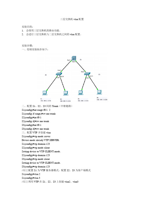
实验步骤:一、绘制实验拓扑如下:二、配置S1、S2、S3间的Trunk(中继链路)S1(config)#int range f0/1 -2S1(config-if-range)#sw mo trunkS2(config)#int f0/1S2(config-if)#sw mo trunkS3(config)#int f0/1S3(config-if)#sw mo trunk三、配置VTP并创建vlanS1(config)#vtp mode serverDevice mode already VTP SERVER.S1(config)#vtp domain 123S2(config)#vtp mode clientSetting device to VTP CLIENT mode.S2(config)#vtp domain 123S3(config)#vtp mode clientSetting device to VTP CLIENT mode.S3(config)#vtp domain 123//以上配置S1为VTP服务器模式,配置S2、S3为客户端模式S1(config)#vlan 2S1(config)#vlan 3//以上利用VTP在S1、S2、S3上创建vlan2、vlan3四、配置三层交换机S1的路由功能下的vlanS1(config)#ip routing //打开三层交换机的路由功能S1(config)#int vlan 2S1(config-if)#ip add 192.168.2.1 255.255.255.0S1(config-if)#no shut //启用vlan2//以上为vlan2配置ipS1(config)#int vlan 3S1(config-if)#ip add 192.168.3.1 255.255.255.0S1(config-if)#no shut //启用vlan3//以上为vlan3配置ip五、配置S2、S3交换机的vlan接口S2(config)#int f0/3S2(config-if)#switchport access vlan 2 //端口f0/3划入vlan 2S2(config)#int f0/4S2(config-if)#switchport access vlan 3 //端口f0/4划入vlan 3S3(config)#int f0/3S3(config-if)#switchport access vlan 2 //端口f0/3划入vlan 2S3(config)#int f0/4S3(config-if)#switchport access vlan 3 //端口f0/4划入vlan3六、主机配置主机1、3分配192.168.2.0网段地址,网关为:192.168.2.1主机2、4分配192.168.3.0网段地址,网关为:192.168.3.1七、测试连通性配置完成后,两个VLAN(VLAN2、VLAN3)就可以通过三层交换机进行通信了。
三层交换机详细配置实例(图)
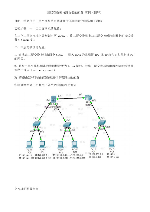
三层交换机与路由器的配置实例(图解)目的:学会使用三层交换与路由器让处于不同网段的网络相互通信实验步骤:一:二层交换机的配置:在三个二层交换机上分别划出两VLAN,并将二层交换机上与三层交换或路由器上的接线设置为trunk接口二:三层交换机的配置:1:首先在三层交换上划出两个VLAN,并进入VLAN为其配置IP,此IP将作为与他相连PC 的网关。
2:将与二层交换机相连的线同样设置为trunk接线,并将三层交换与路由器连接的线设置为路由接口(no switchsport)3:将路由器和下面的交换机进行单臂路由的配置实验最终结果:拓扑图下各个PC均能相互通信交换机的配置命令:SW 0:Switch>Switch>enSwitch#confConfiguring from terminal, memory, or network [terminal]?Enter configuration commands, one per line. End with CNTL/Z.Switch(config)#vlan 2Switch(config-vlan)#exitSwitch(config)#int f0/2Switch(config-if)#switchport access vlan 2Switch(config-if)#no shutSwitch(config-if)#int f0/3Switch(config-if)#switchport mode trunk%LINEPROTO-5-UPDOWN: Line protocol on Interface FastEthernet0/3, changed state to down%LINEPROTO-5-UPDOWN: Line protocol on Interface FastEthernet0/3, changed state to upSwitch(config-if)#exitSwitch(config)#SW 1:Switch>enSwitch#confConfiguring from terminal, memory, or network [terminal]?Enter configuration commands, one per line. End with CNTL/Z.Switch(config)#int f0/2Switch(config-if)#switchport access vlan 2% Access VLAN does not exist. Creating vlan 2Switch(config-if)#no shutSwitch(config-if)#exitSwitch(config)#int f0/3Switch(config-if)#switchport mode trunk%LINEPROTO-5-UPDOWN: Line protocol on Interface FastEthernet0/3, changed state to down%LINEPROTO-5-UPDOWN: Line protocol on Interface FastEthernet0/3, changed state to upSwitch(config-if)#SW 2:Switch>enSwitch#confConfiguring from terminal, memory, or network [terminal]?Enter configuration commands, one per line. End with CNTL/Z.Switch(config)#int f0/2Switch(config-if)#switchport access vlan 2% Access VLAN does not exist. Creating vlan 2Switch(config-if)#exitSwitch(config)#int f0/3Switch(config-if)#switchport mode trunkSwitch(config-if)#三层交换的配置命令:Switch>enSwitch#confConfiguring from terminal, memory, or network [terminal]?Enter configuration commands, one per line. End with CNTL/Z.Switch(config)#int f0/1Switch(config-if)#switchport mode trunk%LINEPROTO-5-UPDOWN: Line protocol on Interface FastEthernet0/2, changed state to downSwitch(config-if)#exitSwitch(config)#int f0/2Switch(config-if)#switchport mode trunkSwitch(config-if)#exitSwitch(config)#vlan 2Switch(config-vlan)#exitSwitch(config)#int vlan 1Switch(config-if)#no shut%LINK-5-CHANGED: Interface Vlan1, changed state to up%LINEPROTO-5-UPDOWN: Line protocol on Interface Vlan1, changed state to up Switch(config-if)#ip address 192.168.1.168 255.255.255.0Switch(config-if)#exitSwitch(config)#int vlan 2%LINK-5-CHANGED: Interface Vlan2, changed state to up%LINEPROTO-5-UPDOWN: Line protocol on Interface Vlan2, changed state to upSwitch(config-if)#ip addSwitch(config-if)#ip address 192.168.2.168 255.255.255.0Switch(config-if)#%LINK-5-CHANGED: Interface FastEthernet0/3, changed state to up%LINEPROTO-5-UPDOWN: Line protocol on Interface FastEthernet0/3, changed state to upSwitch(config-if)#exitSwitch(config)#int f0/3Switch(config-if)#no switchport%LINEPROTO-5-UPDOWN: Line protocol on Interface FastEthernet0/3, changed state to down%LINEPROTO-5-UPDOWN: Line protocol on Interface FastEthernet0/3, changed state to upSwitch(config-if)#Switch(config-if)#ip address 192.168.10.1 255.255.255.0Switch(config-if)#no shutSwitch(config-if)#exitSwitch(config)#ip routingSwitch(config-if)#exitSwitch(config)#ip route 0.0.0.0 0.0.0.0 192.168.10.2Switch(config)#路由器的配置:Router>enRouter#confConfiguring from terminal, memory, or network [terminal]?Enter configuration commands, one per line. End with CNTL/Z.Router(config)#int f0/0Router(config-if)#no shut%LINK-5-CHANGED: Interface FastEthernet0/0, changed state to upRouter(config-if)#exitRouter(config)#int f0/1Router(config-if)#no shut%LINK-5-CHANGED: Interface FastEthernet0/1, changed state to up%LINEPROTO-5-UPDOWN: Line protocol on Interface FastEthernet0/1, changed state to upRouter(config-if)#exitRouter(config)#int f0/0Router(config-if)#no shutRouter(config-if)#exitRouter(config)#int f0/0.1Router(config-subif)#encapsulation dot1Q 1Router(config-subif)#ip address 192.168.3.168 255.255.255.0Router(config-subif)#exitRouter(config)#int f0/0.2Router(config-subif)#encapsulation dot1Q 2Router(config-subif)#ip addRouter(config-subif)#ip address 192.168.4.168 255.255.255.0Router(config-subif)#exitRouter(config)#ip route 0.0.0.0 0.0.0.0 192.168.10.1Router(config)#exit%SYS-5-CONFIG_I: Configured from console by consoleRouter#confConfiguring from terminal, memory, or network [terminal]?Enter configuration commands, one per line. End with CNTL/Z.Router(config)#int f0/1Router(config-if)#ip addRouter(config-if)#ip address 192.168.10.2 255.255.255.0 Router(config-if)#。
三层交换机配置

路由与交换实验报告用三层交换机实现不同vlan间的通信电信学院14级网络一班实验一三层交换机实验目的:利用三层交换机实现不同vlan间的通信。
实验原理:在交换网络中,通过vlan对一个物理网络进行逻辑划分,不同的vlan之间无法直接访问的,必须通过三层的路由设备进行连接。
一般利用路由器或三层交换机来实现不同vlan之间的相互访问。
三层交换机和路由器具备网络层的功能,能够根据数据的IP包头信息,进行选路和转发,从而实现不同网段之间的访问。
实验设备:三层交换机1台、二层交换机2台、pc机两台。
拓扑图:命令及截图:1. SW1: 配置switch# enableswitch# configuration tswitch(config)# hostname SW1SW1#exitSW1(config)#VLAN10SW1(config-vlan)#interface VLAN10SW1(config-VLAN)#ip address 192.168.10.1 255.55.255.0SW1(config-vlan)#exitSW1(config-vlan)#VLAN20SW1(config-vlan)# interface VLAN20SW1(config-VLAN)#ip address 192.168.20.1 255.55.255.0SW1(config-vlan)#exitSW1(config)#interface fa 0/1-3SW1(config)# switchport mode trunkSW1(config-vlan)#exit2.SW2配置switch# enableswitch# configuration tswitch(config)# hostname SW2SW2#exitSW2(config)#interface fa0/3SW2(config-if)#switchport mode accessSW2(config-if)# switchport access VLAN10 SW2(config-if)#exitSW2(config)#interface fa0/1SW2(config-if)#switchport mode trunk SW2(config-if)#exit3. SW3配置switch# enableswitch# configuration tswitch(config)# hostname SW3SW3#exitSW3(config)#interface fa0/3SW3(config-if)#switchport mode access SW3(config-if)# switchport access VLAN20 SW3 (config-if)#exitSW3(config)#interface fa0/1SW3(config-if)#switchport mode trunk SW3(config-if)#exit测试方案及截图:实验结论:利用三层交换机可以实现不同vlan之间的通信实验中遇到的问题及解决方法:无。
CCNA实验三层交换机和单臂路由
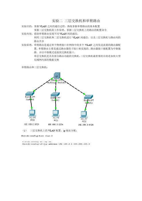
实验二三层交换机和单臂路由实验目的:掌握VLAN之间的通信过程,熟练掌握单臂路由的基本配置掌握三层交换机的工作原理,掌握三层交换机上的路由的配置命令实验内容:借助单臂路由实现不同VLAN间的通信,利用三层交换机和二层交换机进行VLAN间通信,以及三层交换机与路由间的路由共享实验原理:单臂路由是通过单个物理接口在网络中的多个VLAN之间发送流量的路由器配置,单臂路由主要是通过路由器的子接口来实现的。
路由器接口被配置为中继链路,并以中继模式连接到交换机接口。
单层交换机是具有部分路由功能的交换机,三层交换机最重要的目的是加快大型局域网内部的数据交换单臂路由和三层交换机:(1)三层交换机上的VLAN配置,ip地址分配:(2)非常重要也是容易忘记配的是给交换机的对应端口指定对应的vlan显示:表示分好了。
注意:pc机也要配ip地址及网关(2)此时三层交换机已经可以通信(3)下面看单臂路由配置拓扑:(4)pc机配ip(5)路由器上划分子接口以及分配ip地址:(6)交换机上和路由器的接口配truck灯变绿(7)很重要的一点,路由器上的端口要shutdown(8)交换机上创建vlan并给端口分配vlan(9)出错,,自己的网关ping不通查看可知,路由器的子接口根本没有ip地址.经过排查知道了子接口划分时,也要分配ip地址必须要在子接口需要封装的dot1q协议每个子接口都要封装,其中dot1q 后面是对应的局域网号。
(10)可以拼通。
(11)连接路由和交换机,使整个网络通讯。
路由器、交换机上配ip地址。
关闭交换机的二层交换功能开启三层交换机的路由功能(12)交换机和路由器的路由协议配置。
注意哦,自己所在的网络也要广播。
(13)检查:。
Cisco CCNA交换部分实验拓扑图

Cisco CCNA交换部分实验拓扑图一、实验拓扑图实验要求:(1)、VLAN2与VLAN3到外网WEB的路径为:RW1—R1—Internet(2)、VLAN4与VLAN5到外网WEB的路径为:RW2—R1—Internet(3)、无论断开哪个端口,整个网络不间断,三层交换实现网络互通(4)、外网不能访问SW3内的服务器,能和其它主机正常通信;本公司的所有主机能访问服务器。
(5)、RW1、RW2、SW3上实现通道捆绑,实现负载均衡。
VTP、STP、PVST、DHCP、以太网通道捆绑、RIP、三层交换。
四、详细配置清单(分段详解)(1)、VTP:RW1:RW1(config)#vtp domain Tang #RW1作为VTP服务器,设置域RW1(config)#vtp prunning 名为TangRW1(config)#vtp version 2RW1#vlan databaseRW1(vlan)#vl 2RW1(vlan)#vl 3RW1(vlan)#vl 4RW1(vlan)#vl 5RW1(vlan)#vl 127RW1(config)#int ra f0/1 – 6RW1(config-rang-if)#switchport trunk encap dot1qRW1(config-rang-if)#sw mo trunkRW1(config)#int ra f0/1 – 2 #f0/1和f0/2进行捆绑在一起RW1(config-rang-if)channel-group 1 mode onRW1(config)#port-channel load-balance src-mac #基于源和目标MAC负载均衡RW1(config)#int ra f0/3– 4RW1(config-rang-if)channel-group 2 mode onRW1(config)#port-channel load-balance src-macRW2:RW2(config)#int ra f0/1 – 6RW2(config-rang-if)#switchport trunk encap dot1qRW2(config-rang-if)#sw mo trunkRW2config)#int ra f0/1 – 2RW2config-rang-if)# channel-group 1 mode onRW2config)#port-channel load-balance src-macRW2config)#int ra f0/3– 4RW2config-rang-if) # channel-group 3 mode onRW2(config)#port-channel load-balance src-macSW1:SW1(configt)#int f0/1SW1(configt)#sw mo trSW1(configt)#int f0/6SW1(configt)#sw mo trSW1#sh vtp status #查看SW1否学习到RW1的VLAN信息S1(config)#vtp mode client #将SW1设为VTP客户端模式SW1(configt)#int f0/2 #将每项端口加入到相应vlan中SW1(configt-if)#sw ac vl 2S1(configt)#int f0/3SW1(configt)#sw ac vl 3SW1(configt)#int f0/4SW1(configt-if)#sw ac vl 4SW1(configt)#int f0/5SW1(configt-if)#sw ac vl 5SW2:SW2(config)#int f0/4SW2(config)#isw mo trSW2(config)#int f0/1SW2(config)#isw mo trSW2#sh vtp status #查看SW2是否学习到RW1的VLAN信息SW2#s (config)#vtp mode client #将SW2为VTP客户端模式SW2(configt)#int f0/2 #将每项端口加入到相应vlan中SW2(configt-if)#sw ac vl 2SW2(configt)#int f0/3SW2(configt)#sw ac vl 5SW3:SW3(config)#int ra f0/2 – 3 #将f0/2和f0/3捆绑在一起,组号为3 SW3(config-if)#sw mo trSW3(config-if)#channel-group 3 mode onSW3(config)#port-channel load-balance src-macSW3(config)#int ra f0/5 – 6 #将f0/5和f0/6捆绑在一起,组号为2SW3(config-if)#sw mo trSW3(config-if)#channel-group 2 mode onSW3(config)#port-channel load-balance src-macSW3(config)#vtp domain 123 #SW3服务器群专用交换机,不让学习其它的vlan信SW3(config)#vtp mode transparent 息,为其将该交换机更改为透明模式SW3#vl da #创建vlan127,将所有服务器端口加入vlan127SW3(vlan)#vl 127SW3(config)#int ra f0/3 – 8SW3(config-if)#sw ac vl 127。
三层交换机路由实验详细说明

三层交换机路由实验详细说明(一)根据拓扑图分别对SwitchA 和SwitchB 进行配置SwitchA :1. 创建vlan 10,将F0/7划分给 vlan 10。
2. 创建vlan 20,将F0/17划分给vlan 20。
3. 将端口F0/24设置为trunk 模式。
4. 创建虚拟接口vlan 10和vlan 20。
5. 分别为虚拟接口设置IP 地址为其中vlan 10(192.168.10.254/24);vlan 20(192.168.20.254/24)SwitchB :1. 创建vlan 10将F0/7(不是F0/5)划分给 vlan 10。
2. 将端口F0/24设置为trunk 模式。
Pc1:1. 设置IP 地址为192.168.10.12. 网关为192.168.10.254Pc2:1. 设置IP 地址为192.168.20.12. 网关为192.168.20.254Pc3:1. 设置IP 地址为192.168.10.22. 网关为192.168.10.254连通性测试分别在PC1、PC2、PC3上进行连通测试:利用ping 命令。
针对交换机A (三层交换机3760)的配置命令:#config t(config)# ip routing (开启三层交换机的路由功能)(config)# vlan 10 (创建vid 为10 的vlan )(config-vlan)# exit(config)# vlan 20 (创建vid 为20 的vlan )(config-vlan)# exit PC2 SwitchA PC1PC3 F0/24 Vlan 20 F0/24 Vlan 10 F0/7 F0/17 Vlan 10 F0/7 SwitchB(config)# int fast 0/7(config-if)# switch mode access(config-if)# switch access vlan 10 (将0/7端口加入vlan 10中) (config-if)# exit(config)# int fast 0/17(config-if)# switch mode access(config-if)# switch access vlan 20 (将0/17端口加入vlan 20中) (config-if)# exit(config)# int fast 0/24(config-if)# switch mode trunk (将0/24设为trunk模式)(config-if)# switch trunk allowed vlan all (此命令可以不必输入,因为默认是全部允许)(config-if)# exit(创建虚拟接口vlan 10,并设置IP地址和掩码:)(config)# int vlan 10(config-if)# ip addr 192.168.10.254 255.255.255.0(config-if)# exit(创建虚拟接口vlan 20,并设置IP地址和掩码:)(config)# int vlan 20(config-if)# ip addr 192.168.20.254 255.255.255.0(config-if)# exit针对交换机B(二层交换机2126)的配置命令:#config t(config)# vlan 10 (创建vid 为10 的vlan)(config-vlan)# exit(config)# int fast 0/7(config-if)# switch mode access(config-if)# switch access vlan 10 (将0/7端口加入vlan 10中) (config-if)# exit(config)# int fast 0/24(config-if)# switch mode trunk (将0/24设为trunk模式)(config-if)# switch trunk allowed vlan all (此命令可以不必输入,因为默认是全部允许)(config-if)# exit注意:(一)配置好交换机之后不要任意插拔网线,否则要重新配置有关的端口。
思科三层交换机配置总结

思科三层交换机配置总结思科交换机的基本配置命令学习CISCO交换机基本配置:Console端口连接用户模式hostname# ;特权模式hostname(config)# ;全局配置模式hostname(config-if)# ;交换机口令设置:switch>enable ;进入特权模式switch#config terminal ;进入全局配置模式switch(config)#hostname csico ;设置交换机的主机名switch(config)#enable secret csico1 ;设置特权加密口令switch(config)#enable password csico8 ;设置特权非密口令switch(config)#line console 0 ;进入控制台口switch(config-line)#line vty 0 4 ;进入虚拟终端switch(config-line)#login ;虚拟终端允许登录switch(config-line)#password csico6 ;设置虚拟终端登录口令csico6switch#exit ;返回命令交换机VLAN创建,删除,端口属性的设置,配置trunk端口,将某端口加入vlan中,配置VTP:switch#vlan database ;进入VLAN设置switch(vlan)#vlan 2 ;建VLAN 2switch(vlan)#vlan 3 name vlan3 ;建VLAN 3并命名为vlan3 switch(vlan)#no vlan 2 ;删vlan 2switch(config)#int f0/1 ;进入端口1switch(config)#speed ? 查看speed命令的子命令switch(config)#speed 100 设置该端口速率为100mb/s (10/auto)switch(config)#duplex ? 查看duplex的子命令switch(config)#duplex full 设置该端口为全双工(auto/half)switch(config)#description TO_PC1 这是该端口描述为TO_PC1 switch(config-if)#switchport access vlan 2 ;当前端口加入vlan 2switch(config-if)#switchport mode trunk ;设置为trunk模式(access模式)switch(config-if)#switchport trunk allowed vlan 1,2 ;设置允许的vlanswitch(config-if)#switchport trunk encap dot1q ;设置vlan 中继switch(config)#vtp domain vtpserver ;设置vtp域名相同switch(config)#vtp password ;设置发vtp密码switch(config)#vtp server ;设置vtp服务器模式switch(config)#vtp client ;设置vtp客户机模式交换机设置IP地址,默认网关,域名,域名服务器,配置和查看MAC地址表:switch(config)#interface vlan 1 ;进入vlan 1switch(config-if)#ip address 192.168.1.1 255.255.255.0 ;设置IP地址switch(config)#ip default-gateway 192.168.1.6 ;设置默认网关switch(config)#ip domain-name /doc/0113809409.html, 设置域名switch(config)#ip name-server 192.168.1.18 设置域名服务器switch(config)#mac-address-table? 查看mac-address-table 的子命令switch(config)#mac-address-table aging-time 100 设置超时时间为100msswitch(config)#mac-address-table permanent 0000.0c01.bbcc f0/3 加入永久地址在f0/3端口switch(config)#mac-address-table restricted static 0000.0c02.bbcc f0/6 f0/7 加入静态地址目标端口f0/6源端口f0/7 switch(config)#endswitch#show mac-address-table 查看整个MAC地址表switch#clear mac-address-table restricted static 清除限制性静态地址交换机显示命令:switch#write ;保存配置信息switch#show vtp ;查看vtp配置信息switch#show run ;查看当前配置信息switch#show vlan ;查看vlan配置信息switch#show interface ;查看端口信息switch#show int f0/0 ;查看指定端口信息switch#show int f0/0 status;查看指定端口状态switch#dir flash: ;查看闪存Cisco路由器配置命令大全网络2010-06-26 06:43:44 阅读657 评论0 字号:大中小订阅 .(1)模式转换命令用户模式----特权模式,使用命令"enable"特权模式----全局配置模式,使用命令"config t"全局配置模式----接口模式,使用命令"interface+接口类型+接口号"全局配置模式----线控模式,使用命令"line+接口类型+接口号"注:用户模式:查看初始化的信息.特权模式:查看所有信息、调试、保存配置信息全局模式:配置所有信息、针对整个路由器或交换机的所有接口接口模式:针对某一个接口的配置线控模式:对路由器进行控制的接口配置(2)配置命令show running config 显示所有的配置show versin 显示版本号和寄存器值shut down 关闭接口no shutdown 打开接口ip add +ip地址配置IP地址secondary+IP地址为接口配置第二个IP地址show interface+接口类型+接口号查看接口管理性show controllers interface 查看接口是否有DCE电缆show history 查看历史记录show terminal 查看终端记录大小hostname+主机名配置路由器或交换机的标识config memory 修改保存在NVRAM中的启动配置exec timeout 0 0 设置控制台会话超时为0service password-encryptin 手工加密所有密码enable password +密码配置明文密码ena sec +密码配置密文密码line vty 0 4/15 进入telnet接口password +密码配置telnet密码line aux 0 进入AUX接口password +密码配置密码line con 0 进入CON接口password +密码配置密码bandwidth+数字配置带宽no ip address 删除已配置的IP地址show startup config 查看NVRAM中的配置信息copy run-config atartup config 保存信息到NVRAM write 保存信息到NVRAMerase startup-config 清除NVRAM中的配置信息show ip interface brief 查看接口的谪要信息banner motd # +信息 + # 配置路由器或交换机的描素信息description+信息配置接口听描素信息vlan database 进入VLAN数据库模式vlan +vlan号+ 名称创建VLANswitchport access vlan +vlan号为VLAN为配接口interface vlan +vlan号进入VLAN接口模式ip add +ip地址为VLAN配置管理IP地址vtp+service/tracsparent/client 配置SW的VTP工作模式vtp +domain+域名配置SW的VTP域名vtp +password +密码配置SW的密码switchport mode trunk 启用中继no vlan +vlan号删除VLANshow spamming-tree vlan +vlan号查看VLA怕生成树议2. 路由器配置命令ip route+非直连网段+子网掩码+下一跳地址配置静态/默认路由show ip route 查看路由表show protocols 显示出所有的被动路由协议和接口上哪些协议被设置show ip protocols 显示了被配置在路由器上的路由选择协议,同时给出了在路由选择协议中使用的定时器等信息router rip 激活RIP协议network +直连网段发布直连网段interface lookback 0 激活逻辑接口passive-interface +接口类型+接口号配置接口为被动模式debug ip +协议动态查看路由更新信息undebug all 关闭所有DEBUG信息router eigrp +as号激活EIGRP路由协议network +网段+子网掩码发布直连网段show ip eigrp neighbors 查看邻居表show ip eigrp topology 查看拓扑表show ip eigrp traffic 查看发送包数量router ospf +process-ID 激活OSPF协议network+直连网段+area+区域号发布直连网段show ip ospf 显示OSPF的进程号和ROUTER-IDencapsulation+封装格式更改封装格式no ip admain-lookup 关闭路由器的域名查找ip routing 在三层交换机上启用路由功能show user 查看SW的在线用户clear line +线路号清除线路3. 三层交换机配置命令配置一组二层端口configure terminal 进入配置状态nterface range {port-range} 进入组配置状态配置三层端口configure terminal 进入配置状态interface {{fastethernet | gigabitethernet} interface-id} | {vlan vlan-id} | {port-channel port-channel-number} 进入端口配置状态no switchport 把物理端口变成三层口ip address ip_address subnet_mask 配置IP地址和掩码no shutdown 激活端口例:Switch(config)# interface gigabitethernet0/2Switch(config-if)# no switchportSwitch(config-if)# ip address 192.20.135.21 255.255.255.0Switch(config-if)# no shutdown配置VLANconfigure terminal 进入配置状态vlan vlan-id 输入一个VLAN号, 然后进入vlan配态,可以输入一个新的VLAN号或旧的来进行修改。
实验三层交换机配置实例
实验三层交换机配置实例前言:在上次我们做了trunk的实验,同时也知道trunk不能实现不同VLAN间通信,需要通过三层设备(路由/三层交换机)来实现。
所以,这次我们就用三层交换机来模拟实现通信。
三层交换技术就是:二层交换技术+三层转发技术。
它解决了局域网中网段划分之后,网段中子网必须依赖路由器进行管理的局面,解决了传统路由器低速、复杂所造成的网络瓶颈问题。
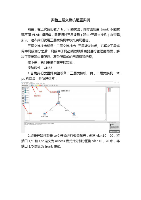
接下来,我们来做个简单的实验:实验软件:GNS31.首先我们放置好实验设备:三层交换机一台,二层交换机一台,pc机两台,并做好标签:2.点击开始并双击sw2开始进行相关配置:创建vlan10,20,将端口1/1和1/2定义为access模式并分别分配到vlan10,20中,将端口1/0定义为trunk模式。
3.双击三层交换机sw1进行相关配置:创建vlan10,20,将端口1/0定义为trunk模式,给虚拟接口vlan10,20配置ip。
4.最后我们给两台pc机配上ip:5.此时配置已全部完成,最后见证奇迹的时刻:可以看到两台pc都能互相通信。
总结:第三层交换机的设计基于对IP路由的仔细分析,把IP路由中每个报文都必须经过的过程提取出来,这个过程是十分简化的过程。
IP路由中绝大多数报文是不包含选项的报文,因此在多数情况下处理报文IP选项的工作是多余的。
不同网络的报文长度是不同的,为了适应不同的网络,IP要实现报文分片的功能,但是在全以太网的环境中,网络的帧长度是固定的,因此报文分片也是一个可以省略的工作。
第三层交换技术没有采用路由器的最长地址掩码匹配的方法,而是使用了精确地址匹配的方法处理,这样,有利于硬件的实现快速查找。
它采用了使用高速缓存的方法,经常使用的主机路由放到了硬件查找表中,只有在这个高速缓存中无法匹配的项目才会通过软件去转发。
在存储转发过程中使用了流交换方式,在流交换中,分析第一个报文确定其是否表示了一个流或者一组具有相同源地址和目的地址的报文。
实验-三层交换机基本配置

交换实验三层交换机基本配置实验名称:三层交换机端口配置实验目的:配置开启三层交换机的三层功能,实现路由作用。
功能描述:为了隔离广播域而划分了VLAN,但不同的VLAN之间需要通信,本实验将实现这一功能。
即同一VLAN里的计算机能跨交换机通信,不同VLAN里的计算机系统也能互相通信。
技术原理:三层交换机是在二层交换的基础上实现了三层的路由功能。
三层交换机基于“一次路由,多次交换”的特性,在局域网环境中转发性能远远高于路由器。
而且三层交换机同时具备二层的功能,能和二层交换机进行很好的数据转发。
三层交换机的以太网接口要比一般的路由器多很多,更加适合多个局域网段之间的互联。
三层交换机本身默认开启了路由功能,可利用IP Routing命令进行控制。
实验设备:S3760一台,PC机2台。
实验拓扑:如下。
注意:先连线,在进行配置,注意连接线缆的接口编号。
S3760为三层交换机。
实验步骤:地址参考如下:s3760-1>enable 14password:s3760-1#configure terminals3760-1 (config)#hostname 3760s3760-1 (config)#ip routing !开启三层交换机的路由功能S3760PC1172.16.50.1/24PC2172.16.50.2/24步骤3. 配置三层交换机端口的路由功能。
s3760-1>enable 14password:s3760-1#configure terminals3760-1 (config)#interface fastethernet 0/12s3760-1 (config-if)#no switchport !开启端口的三层路由功能s3760-1 (config-if)#ip address 172.16.50.12 255.255.255.0s3760-1 (config-if)#no shutdowns3760-1 (config-if)#exits3760-1 (config)#interface fastethernet 0/22s3760-1 (config-if)#no switchport !开启端口的三层路由功能s3760-1 (config-if)#ip address 172.16.50.22 255.255.255.0s3760-1 (config-if)#no shutdowns3760-1 (config-if)#end步骤4. 验证与测试。
实验报告三层交换机静态路由配置

华东师范大学计算机科学技术系上机实践报告课程名称:计算机网络工程年级:2013国培计算机班上机实践成绩:指导教师:陆刚、强志成姓名:黄嘉懿创新实践成绩:实验名称:三层交换机静态路由配置学号:50071200103 上机实践日期:2014-6-11座位编号:3组号:4上机实践时间:学时一、实验目的1. 学会计算机和路由器、交换机的连接2. 掌握IP地址的分配和划分子网的方法3. 掌握路由器/交换机的命令行配置二、实验设备1. PC机4台2. 3560三层交换机1台3. 2811路由器1台4. 平行双绞线4根、交叉双绞线1根三、实验原理网络拓扑图如下:通过路由器实现各不同Vlan之间的通信,路由器工作在OSI模型中的第三层,即网络层。
路由器利用网络层定义的“逻辑”上的网络地址(即IP地址)来区别不同的网络,实现网络的互连和隔离,保持各个网络的独立性。
路由器不转发广播消息,而把广播消息限制在各自的网络内部。
发送到其他网络的数据先被送到路由器,再由路由器转发出去。
同一个子网内的主机可以自由通信,不同子网间的主机不能直接通信。
第 1 页共4 页四、实验步骤1、配置各PC的IP地址和子网掩码及默认网关:A:192.168.10.2 255.255.255.0 192.168.10.1B:192.168.20.2 255.255.255.0 192.168.20.1C:192.168.30.2 255.255.255.0 192.168.30.1D:192.168.40.2 255.255.255.0 192.168.40.12、配置路由器Router>enRouter#conf tEnter configuration commands, one per line. End with CNTL/Z.Router(config)#hostname RR(config)#int f0/1R(config-if)#no shutdown%LINK-5-CHANGED: Interface FastEthernet0/1, changed state to up%LINEPROTO-5-UPDOWN: Line protocol on Interface FastEthernet0/1, changed state to up R(config-if)#ip addr 192.168.30.1 255.255.255.0R(config-if)#exitR(config)#int f0/0R(config-if)#no shutdown%LINK-5-CHANGED: Interface FastEthernet0/0, changed state to up%LINEPROTO-5-UPDOWN: Line protocol on Interface FastEthernet0/0, changed state to up R(config-if)#ip addr 10.0.0.2 255.255.255.0R(config)#ip route 0.0.0.0 0.0.0.0 10.0.0.13、配置三层交换机Switch>enSwitch#conf tEnter configuration commands, one per line. End with CNTL/Z.Switch(config)#hostname SwiSwi(config)#vlan 10Swi(config-vlan)#exitSwi(config)#vlan 20Swi(config-vlan)#exitSwi(config)#vlan 30Swi(config-vlan)#exitSwi(config)#int f0/10Swi(config-if)#switchport mode accessSwi(config-if)#switchport access vlan 10Swi(config-if)#exitSwi(config)#int f0/20Swi(config-if)#switchport mode accessSwi(config-if)#switchport access vlan 20Swi(config-if)#exitSwi(config)#int f0/15Swi(config-if)#switchport mode accessSwi(config-if)#switchport access vlan 30Swi(config-if)#exitSwi(config)#interface vlan 10%LINK-5-CHANGED: Interface Vlan10, changed state to up%LINEPROTO-5-UPDOWN: Line protocol on Interface Vlan10, changed state to up Swi(config-if)#ip addr 192.168.10.1 255.255.255.0Swi(config-if)#exitSwi(config)#interface vlan 20%LINK-5-CHANGED: Interface Vlan20, changed state to up%LINEPROTO-5-UPDOWN: Line protocol on Interface Vlan20, changed state to up Swi(config-if)#ip addr 192.168.20.1 255.255.255.0Swi(config-if)#exitSwi(config)#int vlan 30%LINK-5-CHANGED: Interface Vlan30, changed state to upSwi(config-if)#%LINEPROTO-5-UPDOWN: Line protocol on Interface Vlan30, changed state to up ip addr 192.168.40.1 255.255.255.0Swi(config-if)#exitSwi(config)#int f0/24Swi(config-if)#no switchportSwi(config-if)#ip addr 10.0.0.1 255.255.255.0Swi(config-if)# no shutdownSwi(config-if)#exitSwi(config)#ip route 0.0.0.0 0.0.0.0 10.0.0.2Swi(config)#ip routing4、测试各个Vlan是否连通,结果如下:(1)C PING APC>ping 192.168.10.2Pinging 192.168.10.2 with 32 bytes of data:Request timed out.Reply from 192.168.10.2: bytes=32 time=12ms TTL=126Reply from 192.168.10.2: bytes=32 time=13ms TTL=126Reply from 192.168.10.2: bytes=32 time=13ms TTL=126第 3 页共4 页Ping statistics for 192.168.10.2:Packets: Sent = 4, Received = 3, Lost = 1 (25% loss),Approximate round trip times in milli-seconds:Minimum = 12ms, Maximum = 13ms, Average = 12ms(2)C PING BPC>ping 192.168.20.2Pinging 192.168.20.2 with 32 bytes of data:Reply from 192.168.20.2: bytes=32 time=13ms TTL=126Reply from 192.168.20.2: bytes=32 time=9ms TTL=126Reply from 192.168.20.2: bytes=32 time=13ms TTL=126Reply from 192.168.20.2: bytes=32 time=11ms TTL=126Ping statistics for 192.168.20.2:Packets: Sent = 4, Received = 4, Lost = 0 (0% loss),Approximate round trip times in milli-seconds:Minimum = 9ms, Maximum = 13ms, Average = 11ms(3)C PING DPC>ping 192.168.40.2Pinging 192.168.40.2 with 32 bytes of data:Reply from 192.168.40.2: bytes=32 time=13ms TTL=126Reply from 192.168.40.2: bytes=32 time=12ms TTL=126Reply from 192.168.40.2: bytes=32 time=10ms TTL=126Reply from 192.168.40.2: bytes=32 time=12ms TTL=126Ping statistics for 192.168.40.2:Packets: Sent = 4, Received = 4, Lost = 0 (0% loss),Approximate round trip times in milli-seconds:Minimum = 10ms, Maximum = 13ms, Average = 11ms实验结果表明无论是否在同一Vlan中,都可以ping通。
三层交换机路由功能配置实验总结

三层交换机路由功能配置实验总结三层交换机作为一种网络交换设备,除了基本的交换功能外,还具备了路由功能。
在网络中,路由功能是至关重要的,因为它可以实现不同子网之间的通信。
本文将介绍如何通过三层交换机实现路由功能,并进行实验总结。
一、实验环境本次实验环境如下:1. 三台计算机,分别连接在三个不同的子网中,IP地址分别为:- 192.168.1.2/24- 192.168.2.2/24- 192.168.3.2/242. 三层交换机,具备路由功能,连接以上三个子网。
二、实验步骤1. 配置三层交换机的接口IP地址三层交换机需要为每个接口分配IP地址,以便能够在不同的子网之间进行路由转发。
在本次实验中,我们需要为三个接口分别配置IP 地址:- 接口 VLAN 1:192.168.1.1/24- 接口 VLAN 2:192.168.2.1/24- 接口 VLAN 3:192.168.3.1/24可以通过以下命令进行配置:```interface vlan 1ip address 192.168.1.1 255.255.255.0no shutdowninterface vlan 2ip address 192.168.2.1 255.255.255.0no shutdowninterface vlan 3ip address 192.168.3.1 255.255.255.0no shutdown```2. 配置路由为了实现不同子网之间的通信,需要在三层交换机中配置路由。
在本次实验中,我们需要将两个子网之间的路由添加到路由表中。
假设需要从192.168.1.0/24子网中的计算机访问192.168.3.0/24子网中的计算机,需要将192.168.3.0/24子网的路由添加到路由表中。
可以通过以下命令进行配置:```ip route 192.168.3.0 255.255.255.0 192.168.2.2```其中,192.168.3.0 255.255.255.0表示需要访问的目标子网,192.168.2.2表示下一跳路由器的IP地址。
最新三层交换实验实验报告

最新三层交换实验实验报告实验目的:1. 熟悉三层交换机的基本配置和操作。
2. 掌握VLAN间的路由配置方法。
3. 学习并实现三层交换机的静态路由和动态路由协议配置。
实验环境:1. 三层交换机设备。
2. 多台计算机或网络设备,用于模拟不同VLAN。
3. 网络连接线缆。
4. 网络管理软件,如CLI或Web管理界面。
实验步骤:1. 连接网络设备,并确保所有设备均正确接入三层交换机。
2. 配置交换机的基本设置,包括主机名、管理VLAN等。
3. 创建VLAN,并为每个VLAN分配相应的端口。
4. 在三层交换机上配置IP地址,为不同VLAN提供Layer 3交换功能。
5. 配置VLAN间的路由,可以手动添加静态路由或启用动态路由协议(如RIP、OSPF)。
6. 测试VLAN间的通信,确保路由配置正确无误。
7. 监控网络性能和交换机状态,记录实验数据。
实验结果:1. 成功创建了VLAN,并为每个VLAN分配了正确的端口。
2. 三层交换机的IP地址配置完成,能够进行Layer 3交换。
3. 静态路由和动态路由协议均配置成功,VLAN间通信顺畅。
4. 网络测试显示,数据包能够在不同VLAN间正确传输,无丢包现象。
5. 网络性能稳定,交换机运行状态良好。
实验结论:通过本次实验,我们了解了三层交换机的工作原理和配置方法。
通过实际操作,我们掌握了VLAN间的路由配置,包括静态路由和动态路由协议的设置。
实验结果表明,三层交换机能够有效地实现不同VLAN间的通信,提高了网络的灵活性和扩展性。
此外,实验过程中对网络性能的监控也证实了三层交换机的稳定性和可靠性。
实验二、三层交换机配置

三、实验设备
设备类型 三层交换机 路由器 计算机 数量 1台 1台 2台 设备类型 直接线 交叉线 数量 2根 1根
设备类型
数量
用途
计算机 配置线(console)
2台 2根
配置交换机和路由器 配置交换机和路由器
四、实验内容
1、配置计算机的IP地址。 2、三层交换机划分VLAN。 3、配置三层交换机的路由功能。 4、配置路由器。
(5)配置三层交换机的路由(rip) SW(config)#router rip SW(config-router)#version 2 SW(config-router)#network 192.168.1.0 SW(config-router)#network 192.168.2.0 SW(config-router)#network 12.1.1.0 SW(config-router)#exit
&loopback 0 接口(loop 0) ISP(config)#int loop 0 ISP(config-if)#ip address 1.1.1.1 255.255.255.0 ISP(config-if)#exit
(2)配置路由器的路由(rip) ISP(config)#router rip ISP(config-router)#version 2 ISP(config-router)#network 1.1.1.0 ISP(config-router)#network 12.1.1.0 ISP(config-router)#exit
五、实验拓扑图
六、实验步骤
1、配置计算机的IP地址。(以PC1为例)
思科三层交换机配置

思科三层交换机配置思科三层交换机配置为解决vlan间的路由问题,我们引进三层交换概念,它被大家称为二层交换+三层转发。
三层交换机相当于多个专门处理vlan间路由的多个单臂路由和交换的集成。
三层交换机的转发原理三层交换机通过硬件来交换和路由选择数据包。
为处理数据包的高层信息,三层交换有两种体系结构:1> 传统的MLS(Multilayer Switching)依靠ASIC(Application-Specific Integrated Circuit)对数据流的第一个数据包进行路由处理后,第三层引擎对硬件交换组件进行程序处理为后续数据包提供路由。
产生MLS条目记录,一次路由多次交换。
2> 基于CEF(Cisco Express Forwarding)的MLSCEF是基于拓扑的转发模型,它预先将所有路由信息加入到转发信息库(FIB),方便快速路由。
基本概念有:转发信息库(FIB):类似路由表,记录IP与vlan的对应关系邻接关系表:类似mac地址表,记录相邻接口所连接主机的'mac 地址虚接口:不依赖物理接口的子接口,开启vlan配置网关,属于该vlan的物理接口即可动态充当vlan的网关三层交换机配置三层交换机的接口默认是二层接口,命令switchport 转换为三层接口,相反no switchport将路由接口转为交换接口。
以下面模拟图配置为例。
配置步骤:1>在二层交换机上创建vlan,并分配端口,f0/0端口配置trunk(命令略)2>在三层交换机上创建vlan,并配置trunk指定接口封装方式SW_3L(config)# int f0/0SW_3L(config-if)# switchport trunk encapsulation dot1qSW_3L(config-if)# switchport mode trunk3> 在三层交换机上配置各vlan的ip地址SW_3L(config)# int vlan 10SW_3L(config-if)# ip add 192.168.1.1 255.255.255.0SW_3L(config-if)# no shvlan20和vlan30略4> 三层交换机启用路由,配置接口ipSW_3L(config)# ip routingSW_3L(config)# int f1/0SW_3L(config-if)# no switchportSW_3L(config-if)# ip add 10.1.1.1 255.255.255.248SW_3L(config-if)# no sh5> 为三层交换机配置默认路由SW_3L(config)# ip route 0.0.0.0 0.0.0.0 10.1.1.2经过上面配置,在对客户机设置ip和网关,不同vlan间已经可以正常通信。
三层交换机配置

学院:计算机学院班级:网络112班学号:201100824205 姓名:单海丽三层交换机的配置1、实验目的(1)、掌握三层交换机的工作原理。
(2)、掌握三层交换机上路由的配置命令和步骤。
(3)、学习配置三层交换机的命令和步骤。
2、实验内容利用三层交换机和二层交换机进行VLAN间的通信,以及三层交换机与路由器之间的路由共享情况,给出通信测试。
3、实验原理三层交换机就是具有理由器功能的交换机。
三层交换机的最重要的目的是加快大型局域网内部的数据交换,所具有的路由功能也是为这一目的服务的,能够做到一次路由,多次转发。
对于数据包转发等规律的过程由硬件高速实现,而像路由信息更新、路由表维护、路由确定等功能由软件实现。
出于安全和管理方便考虑,只要是为了减小广播风暴的危害,必须把大型局域网按功能或因素划分成一个个小的局域网,这就使VLAN技术在网络中得以大量应用。
而各个不同VLAN间的通信都要经过路由器来完成转发,随着网间互访的不断增加,单纯使用路由器来实现网间访问,不但因为端口数量有限,而且路由速度慢,从而限制了网络的规模和访问速度。
基于这种情况,三层交换机便应运而生。
三成交换机是为IP设计的,接口类型简单,拥有很强的二层帧处理能力,非常适用于大型局域网内的数据路由与交换,它既可以工作在协议的第三层替代或部分完成传统路由器的功能,同时又具有几乎第二层交换的速度,而价格相对便宜些4、实验环境与网络拓扑5、实验步骤(1)、三层交换机VLAN的基本配置(2)、三层交换机上VLAN的IP地址配置(4)、交换机和路由器的路由协议配置(5)、查看三层交换机的路由表6、实验故障与调试三层交换机和路由器的路由表应该是一样的,而且是具有全网络的路由信息。
拓扑中的任何两台设备之间都可以进行通信。
如果出现问题,要查看VLAN是否配置正确,VLAN 的IP地址是否有误,Trunk链路是否正确,路由协议是否配置正确。
7、实验心得通过对三层交换机的配置,我们了解到了大型局域网内的网络通信情况,对实际的网络由了更深的了解。
3层交换机配置实验报告
页眉内容实验名称:3层交换机配置一.实验目的和要求了解DES-3326SR的虚端口的设置了解单台DES 3326SR直接路由的设置了解多台DES 3326SR静态路由的设置二.实验原理和内容1.网络硬件环境的准备2.对等网络的建立3.通过交换机实现VLAN的划分与通信4.通过路由器实现不同VLAN之间的通信5.无线局域网的组建三、实验步骤步骤1:交换机1,2VLAN配置分别配置交换机1,交换机2的VLAN,保证每个交换机至少各有2个VLAN 可以正常工作,假设:交换机1(VLAN2和VLAN3)交换机2(VLAN6和VLAN7)注:配置指令参见实验1,这里不再详细说明步骤2:交换机1,2虚接口配置分别为交换机1,交换机2的每个VLAN配置虚接口,1:配置指令为:Create ipif <虚接口名称><虚接口IP地址>/<子网掩码长度><虚接口对应的vlan名称>例如:create ipif 192.168.2.1/24 vlan22:查看指令为:Show ipif步骤3:交换机1,2级联端口配置分别为交换机1,交换机2创建VLAN5,VLAN5成员为两台交换机的级联端口(即两交换机的连线端口号),同时创建VLAN的虚接口配置1:配置指令为:a.两台交换机均执行如下指令,创建vlan5,并增加级联端口Create vlan vlan5 tag 5Congfig vlan vlan5 add untag 2b.两台交换机均执行如下指令,创建vlan5虚接口Create ipif if5 192.168.5.1/24 vlan5 state enableCreate ipif if5 192.168.5.2/24 vlan5 state enable注:此处两个虚接口属于同一网段,不允许使用相同的IP地址步骤4:交换机路由配置分别为交换机1,交换机2创建静态路由a.交换机1Create iproute 192.168.2.0/24 192.168.5.1Create iproute 192.168.3.0/24 192.168.5.1b.交换机2Create iproute 192.168.6.0/24 192.168.5.2Create iproute 192.168.7.0/24 192.168.5.2步骤5:测试配置结束后,VLAN2,VLAN3,VLAN6,VLAN7能够全部互通实验名称:3层交换机配置一.实验目的和要求了解DES-3326SR的虚端口的设置了解单台DES 3326SR直接路由的设置了解多台DES 3326SR静态路由的设置二.实验原理和内容1.网络硬件环境的准备2.对等网络的建立3.通过交换机实现VLAN的划分与通信4.通过路由器实现不同VLAN之间的通信5.无线局域网的组建三.主要仪器设备Dlink-3624SR交换机*2四.实验步骤步骤1:交换机1,2VLAN配置分别配置交换机1,交换机2的VLAN,保证每个交换机至少各有2个VLAN 可以正常工作,假设:交换机1(VLAN2和VLAN3)交换机2(VLAN6和VLAN7)注:配置指令参见实验1,这里不再详细说明步骤2:交换机1,2虚接口配置分别为交换机1,交换机2的每个VLAN配置虚接口,1:配置指令为:Create ipif <虚接口名称><虚接口IP地址>/<子网掩码长度><虚接口对应的vlan名称>例如:create ipif 192.168.2.1/24 vlan22:查看指令为:Show ipif步骤3:交换机1,2级联端口配置分别为交换机1,交换机2创建VLAN5,VLAN5成员为两台交换机的级联端口(即两交换机的连线端口号),同时创建VLAN的虚接口配置1:配置指令为:a.两台交换机均执行如下指令,创建vlan5,并增加级联端口Create vlan vlan5 tag 5Congfig vlan vlan5 add untag 2b.两台交换机均执行如下指令,创建vlan5虚接口Create ipif if5 192.168.5.1/24 vlan5 state enableCreate ipif if5 192.168.5.2/24 vlan5 state enable注:此处两个虚接口属于同一网段,不允许使用相同的IP地址步骤4:交换机路由配置分别为交换机1,交换机2创建静态路由a.交换机1Create iproute 192.168.2.0/24 192.168.5.1Create iproute 192.168.3.0/24 192.168.5.1b.交换机2Create iproute 192.168.6.0/24 192.168.5.2Create iproute 192.168.7.0/24 192.168.5.2步骤5:测试配置结束后,VLAN2,VLAN3,VLAN6,VLAN7能够全部互通五.实验记录和处理VLAN及端口配置:交换机1:交换机2:网关配置:交换机1:交换机2:交换机1:2实验结果截图:口配置正确,交换机路由配置正确,不同VLAN间能够通过它们互相连通。
实验项目9:三层交换机的配置

M3560(config-if)#int f0/2
M3560(config-if)#ip add 192.168.7.1 255.255.255.248
M3560(config-if)#no shut
M3560(config-if)#int fa0/3
M3560(config)#int range fa0/1 -3
M3560(config-if-range)#no switchport //开启端口的路由功能
M3560(config-if-range)#int f0/1
M3560(config-if)#ip add 192.168.7.9 255.255.255.248
3、熟练掌握思科三层交换机的配置命令与步骤,使不同网段的设备能互通。
二、实验拓扑图
三、实验步骤
1、Ming1交换机配置过程
Switch>en
Switch#conf t
Switch(config)#hostname M3560
M3560(config)#no ip domain-lookup //关闭动态域名解析
M3560(config-if)#ip add 192.168.7.17 255.255.255.248
M3560(config-if)#no shut
M3560(config)#ip routing
2、DNS、邮箱设置
实验心得
通过此次实验我学会了如何把三层交换机当成路由器来使用,并且学会了如何配置邮箱服务器,还有客户端邮箱设置与发送。
三层交换机的配置实验报告
课程名称
交换机配置
实验项目名称
实验项目9:三层交换机的配置
- 1、下载文档前请自行甄别文档内容的完整性,平台不提供额外的编辑、内容补充、找答案等附加服务。
- 2、"仅部分预览"的文档,不可在线预览部分如存在完整性等问题,可反馈申请退款(可完整预览的文档不适用该条件!)。
- 3、如文档侵犯您的权益,请联系客服反馈,我们会尽快为您处理(人工客服工作时间:9:00-18:30)。
比较全面的三层交换机配置实例(带命令解释哟!)Enable //进入私有模式Configure terminal //进入全局模式service password-encryption //对密码进行加密hostname Catalyst 3550-12T1 //给三层交换机定义名称enable password 123456. //enable密码Enable secret 654321 //enable的加密密码(应该是乱码而不是654321这样)Ip subnet-zero //允许使用全0子网(默认都是打开的)Ip name-server 172.16.8.1 172.16.8.2 //三层交换机名字Catalyst 3550-12T1对应的IP地址是172.16.8.1Service dhcp //提供DHCP服务ip routing //启用三层交换机上的路由模块ExitVtp mode server //定义VTP工作模式为sever模式Vtp domain centervtp //定义VTP域的名称为centervtpVlan 2 name vlan2 //定义vlan并给vlan取名(如果不取名的话,vlan2的名字应该是vlan002)Vlan 3 name vlan3Vlan 4 name vlan4Vlan 5 name vlan5Vlan 6 name vlan6Vlan 7 name vlan7Vlan 8 name vlan8Vlan 9 name vlan9Exitinterface Port-channel 1 //进入虚拟的以太通道组1switchport trunk encapsulation dot1q //给这个接口的trunk封装为802.1Q的帧格式switchport mode trunk //定义这个接口的工作模式为trunkswitchport trunk allowed vlan all //在这个trunk上允许所有的vlan通过Interface gigabitethernet 0/1 //进入模块0上的吉比特以太口1switchport trunk encapsulation dotlq //给这个接口的trunk封装为802.1Q的帧格式switchport mode trunk //定义这个接口的工作模式为trunkswitchport trunk allowed vlan all //在这个trunk上允许所有的vlan通过channel-group 1 mode on //把这个接口放到快速以太通道组1中Interface gigabitethernet 0/2 //同上switchport trunk encapsulation dotlqswitchport mode trunkswitchport trunk allowed vlan allchannel-group 1 mode onport-channel load-balance src-dst-ip //定义快速以太通道组的负载均衡方式(依*源和目的IP的方式)interface gigabitethernet 0/3 //进入模块0上的吉比特以太口3switchport trunk encapsulation dotlq //给trunk封装为802.1Qswitchport mode trunk //定义这个接口的工作模式为trunkswitchport trunk allowed vlan all //允许所有vlan信息通过interface gigabitethernet 0/4 //同上switchport trunk encapsulation dotlqswitchport mode trunkswitchport trunk allowed vlan allinterface gigbitethernet 0/5 //同上switchport trunk encapsulation dotlqswitchport mode trunkswitchport trunk allowed vlan allinterface gigbitethernet 0/6 //同上switchport trunk encapsulation dotlqswitchport mode trunkswitchprot trunk allowed vlan allinterface gigbitethernet 0/7 //进入模块0上的吉比特以太口7Switchport mode access //定义这个接口的工作模式为访问模式switchport access vlan 9 //定义这个接口可以访问哪个vlan(实际就是分配这个接口到vlan)no shutdownspanning-tree vlan 6-9 cost 1000 //在生成树中,vlan6-9的开销定义为10000nterface range gigabitethernet 0/8 –10 //进入模块0上的吉比特以太口8,9,10 switchport mode access //定义这些接口的工作模式为访问模式switchport access vlan 8 //把这些接口都分配到vlan8中no shutdownspanning-tree portfast //在这些接口上使用portfast(使用portfast以后,在生成树的时候不参加运算,直接成为转发状态)interface gigabitethernet 0/11 //进入模块0上的吉比特以太口11switchport trunk encapsulation dotlq //给这个接口封装为802.1Qswitchport mode trunk //定义这个接口的工作模式为trunkswitchport trunk allowed vlan all //允许所有vlan信息通过interface gigabitethernet 0/12 //同上switchport trunk encapsulation dotlqswitchport mode trunkswitchport trunk allowed vlan allinterface vlan 1 //进入vlan1的逻辑接口(不是物理接口,用来给vlan做路由用)ip address 172.16.1.7 255.255.255.0 //配置IP地址和子网掩码no shutdownstandby 1 ip 172.16.1.9 //开启了冗余热备份(HSRP),冗余热备份组1,虚拟路由器的IP地址为172.16.1.9standby 1 priority 110 preempt //定义这个三层交换机在冗余热备份组1中的优先级为110,preempt是用来开启抢占模式interface vlan 2 //同上ip address 172.16.2.252 255.255.255.0no shutdownstandby 2 ip 172.16.2.254standby 2 priority 110 preemptip access-group 101 in //在入方向上使用扩展的访问控制列表101interface vlan 3 //同上ip address 172.16.3.252 255.255.255.0no shutdownstandby 3 ip 172.16.3.254standby 3 priority 110 preemptip access-group 101 ininterface vlan 4 //同上ip address 172.16.4.252 255.255.255.0no shutdownstandby 4 ip 172.16.4.254standby 4 priority 110 preemptip access-group 101 ininterface vlan 5ip address 172.16.5.252 255.255.255.0no shutdownstandby 5 ip 172.16.5.254standby 5 priority 110 preemptip access-group 101 ininterface vlan 6ip address 172.16.6.252 255.255.255.0no shutdownstandby 6 ip 172.16.6.254standby 6 priority 100 preemptinterface vlan 7ip address 172.16.7.252 255.255.255.0no shutdownstandby 7 ip 172.16.7.254standby 7 priority 100 preemptinterface vlan 8ip address 172.16.8.252 255.255.255.0no shutdownstandby 8 ip 172.16.8.254standby 8 priority 100 preemptinterface vlan 9ip address 172.16.9.252 255.255.255.0no shutdownstandby 9 ip 172.16.9.254standby 9 priority 100 preemptaccess-list 101 deny ip any 172.16.7.0 0.0.0.255 //扩展的访问控制列表101access-list 101 permit ip any anyInterface vlan 1 //进入vlan1这个逻辑接口Ip helper-address 172.16.8.1 //可以转发广播(helper-address的作用就是把广播转化为单播,然后发向172.16.8.1)Interface vlan 2Ip helper-address 172.16.8.1Interface vlan 3ip helper-address 172.16.8.1interface vlan 4ip helper-address 172.16.8.1interface vlan 5ip helper-address 172.16.8.1interface vlan 6ip helper-address 172.16.8.1interface vlan 7ip helper-address 172.16.8.1interface vlan 9ip helper-address 172.16.8.1router rip //启用路由协议RIPversion 2 //使用的是RIPv2,如果没有这句,则是使用RIPv1network 172.16.0.0 //宣告直连的网段exitip route 0.0.0.0 0.0.0.0 172.16.9.250 //缺省路由,所有在路由表中没有办法匹配的数据包,都发向下一跳地址为172.16.9.250这个路由器line con 0line aux 0line vty 0 15 //telnet线路(路由器只有5个,是0-4)password 12345678 //login密码loginendcopy running-config startup-config 保存配置。
