MAX9610
MAX9286介绍

Course Introduction and Overview
• Application: In surround-view camera applications, video data from multiple cameras need to be synchronized for processing by a downstream SoC • Limitation of Current Solution: Using single-channel deserializers available today, the video streams need to be synchronized using an FPGA and related software • Implication: Synchronizing multiple video streams using today’s technology requires additional hardware and software • Advantage of Maxim Solution: The MAX9286 allows automatic camera synchronization with no additional hardware or software, thereby lowering design time and cost. The MAX9286 also has link diagnostic features to determine the health of each camera link.
End Applications
Surround-view camera systems Machine vision systems
MAX824替代料

MAX824替代料TOREX XC6101 替换Maxim Semiconductor MAX823/MAX824芯片XC6101品牌:TOREX产地:日本代理商:香港富研科技有限公司特点:采用CMOS工艺生产的, 带有手动复位控制端和看门狗(Watch Dog)功能XC6101~XC6105,XC6111~XC6117系列是采用CMOS工艺生产的, 带有手动复位控制端和看门狗(Watch Dog)功能, 具有高精度, 低功耗特点的电压检测器,内部电路包括参考电压源电路, 延迟电路, 比较器电路和输出驱动电路。
XC6101~XC6105,XC6111~XC6117系列内置时间延迟电路,通过设置外部手动复位功能,可在任何条件下进行强制复位。
该系列芯片提供两种形式的输出方式:VDFL和VDFH当将芯片的WD端子悬空时,XC6101~XC6105,XC6111~XC6117的看门狗功能会被关闭,此条件下,在看门狗超时前,内部计数器清零在芯片内部,由于手动复位端子是连接到VIN的,因此,该功能不需要使用时可以悬空。
XC6101~XC6105,XC6111~XC6117系列检测电压的设置可通过激光微调技术以0.1V为间隔自由选择。
看门狗超时时间设置可在 6.25ms~1.6s有六种选择,解除延迟时间设置在3.13ms ~1.6s有七种供选择。
TOREX XC6101可与Maxim Semiconductor MAX823/MAX824相媲美,替换MAX823/MAX824芯片TOREX XC6101 电压范围1.6V~5.0V ;MAX823/MAX824工作电压+2.5 V,+3 V,+3.3 V和+5 VTOREX XC6101看门狗超时时间设置可在6.25ms~1.6s有六种选择,解除延迟时间设置在3.13ms ~1.6s有七种供选择;MAX823/MAX8241.6s的超时看门狗定时器TOREX XC6101手动复位功能手动复位输入;MAX823/MAX824手动复位输入XC6101特征:检测电压范围1.6V~5.0V ±2% (0.1V 间隔)检测电压带后范围VDF×5%(TYP.)(XC6101~XC6105)VDF×0.1%(TYP.)(XC6111~XC6117工作电压范围1.0V~6.0V検出電圧温度特性±100ppm/℃(TYP.)输出形式N沟道开漏输出, CMOS输出复位输出选择测低时复位信号输出低电平检测低时复位信号输出高电平看门狗功能看门狗端口输入手动复位功能手动复位输入引脚XC6101电路图:XC6101引脚配置:TOREX 品牌优势:TOREX 作为高效率电源IC的专业生产商,特瑞仕拥有电压检测器,电压调整器,温度传感器,功率MOS FET等丰富的产品种类,以满足客户的需求。
Konica AF 35mm 自动对焦相机说明书

• Red indicator light glows in viewfinder to tell user when to use the built-in flash.
Flash . ................ Built-in , pop-up electronic flash . Guide No . 45 (feet) 14 (m.etric) at ASA 100 . Recycle time 5 - 7 seconds. Approximately
132 0 action, with double exposure prevention device. Rewind . . .. . ........ ... . . .. Rapid rewind crank handle. Frame Counter . .. ... Counts number of exposures taken .
Viewfinder Window
Back Cover Release
r-------------'"-----::;nutter Release Button r-----...,--------- Twin Autofocus Sensors r - - - - - Built-in " Pop-Up" Electronic Flash
Cat. No. '106-117'
@Copyrloht 1980 Berkey Marftetlng Companies
KonicaAF
35mmcamera
CrustCrawler Inc. DYNAMIXEL MX-106R 说明书
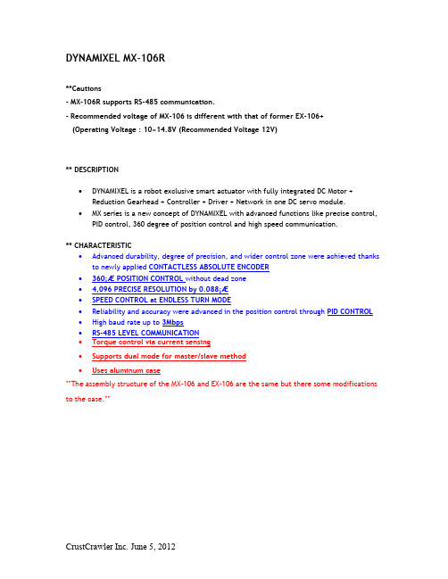
DYNAMIXEL MX-106R**Cautions- MX-106R supports RS-485 communication.- Recommended voltage of MX-106 is different with that of former EX-106+(Operating Voltage : 10~14.8V (Recommended Voltage 12V)** DESCRIPTION•DYNAMIXEL is a robot exclusive smart actuator with fully integrated DC Motor + Reduction Gearhead + Controller + Driver + Network in one DC servo module.•MX series is a new concept of DYNAMIXEL with advanced functions like precise control, PID control, 360 degree of position control and high speed communication.** CHARACTERISTIC•Advanced durability, degree of precision, and wider control zone were achieved thanks to newly applied CONTACTLESS ABSOLUTE ENCODER•360¡Æ POSITION CONTROL without dead zone•4,096 PRECISE RESOLUTION by 0.088¡Æ•SPEED CONTROL at ENDLESS TURN MODE•Reliability and accuracy were advanced in the position control through PID CONTROL •High baud rate up to 3Mbps•RS-485 LEVEL COMMUNICATION•Torque control via current sensing•Supports dual mode for master/slave method•Uses aluminum case**The assembly structure of the MX-106 and EX-106 are the same but there some modifications to the case.**** INCLUDESDescription Qty DYNAMIXEL MX-106R 1 HORN HN05-N101 (MX Exclusive) 1 WASHER Thrust Washer 1 CABLE 4P Cable 200mm 1Wrench Bolt M2.5*4 16pcs BOLT/NUTWrench Bolt M3*8 1pcsNut M2.5 18pcs** H/W SPECSProduct Name MX-106RWeight 153gDimension 40.2mm x 65.1mm x 46mmGear Ratio 225 : 1Operation Voltage (V) 10 12 14.8 Stall Torque (N.m)8.08.410.0 Stall Current (A) 4.8 5.2 6.3 No Load Speed (RPM)414555 Motor Maxon MotorMinimum ControlAngleAbout 0.088¡Æ x 4,096Operating Range Actuator Mode : 360¡Æ Wheel Mode : Endless turnOperating Voltage10~14.8V (Recommended voltage : 12V) Operating Temperature -5¡ÆC ~ 80¡ÆCCommand Signal Digital PacketProtocol RS485 Asynchronous Serial Communication (8bit,1stop, No Parity)Link (physical)RS485 Multi Drop Bus (daisy chain type connector)ID 254 ID (0~253) Baud Rate 8000bps ~ 3MbpsFeedback Functions Position, Temperature, Load, Input Voltage, Current, etc.Material Case : Engineering Plastic Gear : Full MetalPosition Sensor Contactless absolute encoderDefault ID #1 – 57600bps** After purchase, please change ID and baud rate according to your use.** COMPATIBLE PRODUCTS- Controller : CM-2+, CM-700- Interface(I/F) : USB2Dynamixel (RS-485)- NOTICE : Not compatible with the EX-106 horn. (HN05-N101 Set / T101 Set)** CONTROLLING ENVIRONMENT- Software for Dynamixel control : ROBOPLUS - Download- C/C++, C#, Labview, MATLAB, Visual Basic et. : Library – Download**Click here to download 2D and 3D drawings**Click here to go to e-Manual.。
RT9610CGQW规格书

2
DS9610C-01 April 2016
RT9610C
Functional Block Diagram
VCC BOOT
POR UGATE EN VCC R PWM R Tri-State Detect Control Logic Shoot-Through Protection VCC LGATE GND PHASE
Features
Drives Two N-MOSFETs Adaptive Shoot-Through Protection 0.5Ω On-Resistance, 4A Sink Current Capability Supports High Switching Frequency Tri-State PWM Input for Power Stage Shutdown Output Disable Function Integrated Boost Switch Low Bias Supply Current VCC POR Feature Integrated
Ordering Information
RT9610C Package Type QW : WDFN-8L 2x2 (W-Type) Lead Plating System G : Green (Halogen Free and Pb Free)
Note : Richtek produVCC LGATE GND PWM
WDFN-8L 2x2
Functional Pin Description
Pin No. 1 2 3 4 Pin Name EN PHASE UGATE BOOT Pin Function Enable Pin. When low, both UGATE and LGATE are driven low and the normal operation is disabled. Switch Node. Connect this pin to the source of the upper MOSFET and the drain of the lower MOSFET. This pin provides a return path for the upper gate driver. Upper Gate Drive Output. Connect to the gate of high side power N-MOSFET. Floating Bootstrap Supply Pin for Upper Gate Drive. Connect the bootstrap capacitor between this pin and the PHASE pin. The bootstrap capacitor provides the charge to turn on the upper MOSFET. Control Input for Driver. The PWM signal can enter three distinct states during operation. Connect this pin to the PWM output of the controller. Ground. The exposed pad must be soldered to a large PCB and connected to GND for maximum power dissipation. Lower Gate Drive Output. Connect to the gate of the low side power N-MOSFET. Input Supply Pin. Connect this pin to a 5V bias supply. Place a high quality bypass capacitor from this pin to GND.
MAX16141 诊断试验板 通用描述说明书

MAX16141EVKIT#/MAXESSENTIAL01+Evaluates: MAX16141MAX16141 Evaluation Kit General DescriptionThe MAX16141 evaluation kit (EV kit) evaluates the MAX16141 IC family. The MAX16141 is a diode controller and protection device that protects systems against fault conditions, such as reverse-current, overcurrent, input over-voltage/undervoltage, short-circuit, and overtemperature. The MAX16141 EV kit comes with the MAX16141AAF/V+ IC installed. The MAX16141 EV kit undervoltage/overvoltage thresholds are set to 8.6V/36.2V, respectively.Features●8.6V to 36.2V Undervoltage/Overvoltage Thresholds ●Output Short-Circuit Protection●Resistor Adjustable Overvoltage and UndervoltageTrip Threshold ●Proven 2-Layer, 2oz Copper PCB Layout ●Demonstrates Compact Solution Size ●Fully Assembled and Tested319-100230; Rev 0; 8/18Ordering Information appears at end of data sheet.Quick StartRequired Equipment●MAX16141 EV kit●40V, 10A DC power supply●One digital multimeter (DMM)ProcedureThe EV kit is fully assembled and tested. Follow the steps below to verify board operation.Caution: Do not turn on power supply until all connections are completed.1) Verify that shunts are installed onto their respectivedefault positions for jumpers JU1–JU3 (Table 1, Table 2, and Table 3).2) Connect the power supply between the IN andSYSGND terminal posts.3) Connect the DMM between the OUT and SYSGNDterminal posts.4) Turn on the power supply.5) Manually sweep the power supply from 8.6Vto 36.2V. Verify that the output voltage at OUT approximately follows the input voltage at IN.6) Increase the input voltage to 37V.7) Verify that the output voltage is 0V (overvoltageprotection)8) Set the input voltage to 12V and verify that OUT isalso about 12V.9) Using an insulated shorting cable, take caution tohold the insulated parts of the shorting cable while shorting OUT to SYSGND, and verify that the output voltage is 0V (Short circuit protection).10) Remove the shorting cable between OUT andSYSGND and verify that the output voltage is 12V.11) Decrease the input voltage to 7V.12) Verify that the output voltage is approximately 0V(undervoltage protection).FILEDECRIPTION MAX16141 EV BOM EV Kit Bill of MaterialMAX16141 EV PCB Layout EV Kit Layout MAX16141 EV SchematicEV Kit SchematicMAX16141 EV Kit FilesClick here for production status of specific part numbers.Evaluates: MAX16141MAX16141 Evaluation Kit Detailed Description of HardwareThe MAX16141 EV kit evaluates the MAX16141 IC. The MAX16141 is a diode controller and protection device that protects systems against fault conditions such as reverse current, overcurrent, input overvoltage/undervoltage, short circuit and over temperature. The MAX16141 EV kit’s undervoltage and overvoltage thresholds are configured to 8.6V and 36.2V, respectively.The MAX16141 EV kit comes with the MAX16141ATE+ (16-TQFN) installed and is configured to operate normally between 8.6V and 36.2V. Under normal operation, the output follows the input. The output will shut down (0V) when the input is risen above 36.2V (i.e., 37V or higher), or drop below 8.6V (i.e., 7V or lower). The output will also shut down when the load at the output goes above 5A, or in an event of a short circuit at the output.SHDNThe MAX16141 EV kit provides a jumper (JU1) to enable or disable the MAX16141. Refer to Table 1 for JU1 jumper settings.SLEEPThe MAX16141 EV kit provides a jumper (JU2) to pullup the active-low sleep mode input of the MAX16141. Refer to Table 2 for JU2 jumper settings.GATE SnubberFor applications that require slower gate rise time than what is achieved using a resistor from GRC to GND, an external resistor and capacitor (snubber) network can be added from GATE to GND. However, the recommended value is 1k Ω resistor in series with a 10nF cap.The MAX16141 EV Kit provides a jumper (JU3) to add or remove the snubber at the power MOSFET gates. Refer to Table 3 for jumper settings.Overvoltage ProtectionThe MAX16141 EV kit shuts down the output when the input voltage exceeds the upper input voltage limit set by resistors R11 and R9 between the TERM and OVSET pins of the MAX16141. Refer to the equation below to set the overvoltage limit for the MAX16141 EV kit.R11 = ((VOV_TH x R9)/VTH) - (R9 + 700Ω)where,VOV_TH is the desired overvoltage threshold.R9 = 10kΩV TH = 0.5V (typ) threshold for OVSET and 700Ω is the TERM switch typical resistance.Undervoltage ProtectionThe MAX16141 EV kit shuts down the output when the input voltage drops below the lower input voltage limit set by resistors R10 and R8 between the TERM and UVSET pins of the MAX16141. Refer to the equation below to set the undervoltage limit for the MAX16141 EV kit.R10 = ((V UV_TH x R8)/V TH ) - (R8 + 700Ω)where,V UV_TH is the desired undervoltage threshold.R8 = 10kΩV TH = 0.5V (typ) threshold for UVSET and 700Ω is the TERM switch typical resistance.Table 2. SLEEP (JU2)Table 3. GATE Snubber (JU3)Table 1. SHDN (JU1)*Default position.Note: Larger cap values will decrease the gate fall time during reverse-voltage fault.*Default position.*Default position.JU1SHUNT POSITION DESCRIPTIONInstalled*Enabled. SHDN = VCC (through pullup resistor R12)Not Installed Disabled. SHDN = SYSGND (through internal pulldown)JU2SHUNT POSITION DESCRIPTIONInstalled*SLEEP (pullup through resistor R13)Not Installed SLEEP (floating)JU3SHUNT POSITION DESCRIPTIONInstalled GATE snubber (R3 and C7) added Not Installed*GATE snubber (R3 and C7) removedEvaluates: MAX16141MAX16141 Evaluation Kit Overcurrent ProtectionThe MAX16141 EV kit shuts down the output when the load current exceeds the current limit set by the OC_THRESHOLD (See MAX16141 IC data sheet) and the sense resistor R1 between the RS and OUT pins of the MAX16141. Refer to the equation below to set the overcurrent limit for the MAX16141 EV kit.RSENSE = V(RS-OUT)/IOCTHwhere,RSENSE is the sense resistor between RS and OUT in Ω,V(RS-OUT) is the overcurrent threshold in V (refer to the IC data sheet for the proper value)IOCTH is the desired overcurrent threshold in A.Short-Circuit ProtectionThe MAX16141 EV kit shuts down the output in event the output is shorted to ground. The output will resume normal level, same as the input, when the short at the output is removed.Evaluating other ICs in the MAX16141 FamilyThe MAX16141 EV kit comes with the MAX16141AAF/V+ installed. To evaluate other ICs in the MAX16141 IC family, replace U1 with the desired IC and refer to the MAX16141 IC data sheet for additional detail.Note: Indicate that you are using the MAX16141 when contacting these component suppliers.#Denotes RoHSSUPPLIERWEBSITECentral Semiconductor Kemet Murata/TOKO NXP ON Semiconductor PanasonicPARTTYPE MAX16141EVKIT#EV KitComponent SuppliersOrdering InformationEvaluates: MAX16141 MAX16141 Evaluation KitMAX16141 EV Kit Bill of MaterialsITEM REF_DES DNI/DNP QTY MFG PART #MANUFACTURER VALUE DESCRIPTION COMMENTS1C1, C2-2GRM31CR72E104KW03MURATA0.1UF CAPACITOR; SMT (1206); CERAMIC CHIP; 0.1UF; 250V; TOL=10%; TG=-55 DEGC TO +125 DEGC; TC=X7R2C3-1GRM43DR72E334KW01MURATA0.33UF CAPACITOR; SMT (1812); CERAMIC CHIP; 0.33UF; 250V; TOL=10%; TG=-55 DEGC TO +125 DEGC; TC=X7R3C4-1EEE-FK1V331GP PANASONIC330UF CAPACITOR;SMT (CASE_G); ALUMINUM-ELECTROLYTIC; 330UF; 35V; TOL=20%4C7-1C0805C103K1RAC;GRM21BR72A103KA01;08055C103KAT2AKEMET;MURATA;AVX0.01UFCAPACITOR; SMT (0805);CERAMIC CHIP; 0.01UF; 100V;TOL=10%; MODEL=;TG=-55 DEGC TO +125 DEGC;TC=X7R5C8-1GRM1885C1H102JA01;C1608C0G1H102J080MURATA;TDK1000PFCAPACITOR; SMT (0603);CERAMIC CHIP; 1000PF; 50V;TOL=5%; TG=-55 DEGC TO+125 DEGC6COM, IN_PAD,OUT_PAD, SYSGND,SYSGND_PAD_OUT-5MAXIMPAD N/A MAXIMPADEVK KIT PARTS;MAXIM PAD; NO WIRE TO BESOLDERED ON THEMAXIMPAD7COM_TP1, COM_TP2-25001KEYSTONE N/A TEST POINT; PIN DIA=0.1IN; TOTAL LENGTH=0.3IN; BOARD HOLE=0.04IN; BLACK; PHOSPHOR BRONZE WIRE SILVER PLATE FINISH;8D1-1CMPZ5245B CENTRAL SEMICONDUCTOR15V DIODE; ZNR; SMT (SOT-23); VZ=15V; IZ=0.0085A9D2, D3-2CMHZ5231B CENTRAL SEMICONDUCTOR 5.1V DIODE; ZNR; SMT (SOD-123);VZ=5.1V; IZ=0.02A10D4-1BAV300VISHAY BAV300DIODE; SS; SMT (MICROMELF); PIV=60V; IF=0.25A11EN, FAULT, GATE,OVSET, SLEEP, UVSET-65002KEYSTONE N/ATEST POINT; PIN DIA=0.1IN;TOTAL LENGTH=0.3IN; BOARDHOLE=0.04IN; WHITE;PHOSPHOR BRONZE WIRESILVER;12IN, OUT,SYSGND_OUT, TP1-4108-0740-001EMERSON NETWORK POWER108-0740-001CONNECTOR; MALE;PANELMOUNT; BANANAJACK; STRAIGHT; 1PIN13JU1-JU3-3PEC02SAAN SULLINS PEC02SAAN CONNECTOR; MALE; THROUGH HOLE; BREAKAWAY; STRAIGHT; 2PINS14N1, N2-2NVD6824NLT4G ON SEMICONDUCTOR NVD6824NLT4G TRAN; POWER MOSFET; NCH; DPAK; PD-(90W); I-(41A); V-(100V)15R1-1CSSH2728FT5L00STACKPOLE ELECTRONICS INC.0.005RESISTOR; 2728; 0.005 OHM; 1%; 25PPM; 4W; METAL FOIL16R2-1CRCW121010R0FK VISHAY DALE10RESISTOR; 1210; 10 OHM; 1%; 100PPM; 0.5W; THICK FILM17R3-1TNPW06031K00BE;RG1608P-102-BVISHAY DALE;SUSUMU CO LTD.1KRESISTOR; 0603; 1K OHM;0.1%; 25PPM; 0.10W; THICKFILM18R4-1RG1608P-101-B;ERA-3YEB101VSUSUMU CO LTD.;PANASONIC100RESISTOR; 0603; 100 OHM;0.1%; 25PPM; 0.1W; THICKFILM19R6-R9-4CHPHT0603K1002FGT VISHAY SFERNICE10K RESISTOR; 0603; 10K OHM; 1%; 100PPM; 0.0125W; THICK FILM20R10-1CRCW0603162KFK VISHAY DALE162K RESISTOR; 0603; 162K OHM; 1%; 100PPM; 0.1W; THICK FILMEvaluates: MAX16141 MAX16141 Evaluation KitMAX16141 EV Kit Bill of Materials (continued)ITEM REF_DES DNI/DNP QTY MFG PART #MANUFACTURER VALUE DESCRIPTION COMMENTS21R11-1CRCW0603715KFK VISHAY DALE715K RESISTOR; 0603; 715K OHM; 1%; 100PPM; 0.10W; METAL FILM22R12-R14-3ERJ-3EKF1003PANASONIC100K RESISTOR; 0603; 100K OHM; 1%; 100PPM; 0.1W; THICK FILM23R18-1RC0402JR-070RL;CR0402-16W-000RJTYAGEO PHYCOMP;VENKEL LTD.0RESISTOR; 0402; 0 OHM;5%; JUMPER; 0.063W; THICKFILM24SU1-SU3-3S1100-B;SX1100-B KYCON;KYCON SX1100-B TEST POINT; JUMPER; STR; TOTAL LENGTH=0.24IN; BLACK;INSULATION=PBT;PHOSPHOR BRONZE CONTACT=GOLD PLATED25U1-1MAX16141AAF/V+MAXIM MAX16141AAF/V+EVKIT PART - IC; CONTROLLER; IDEAL DIODE CONTROLLER WITH VOLTAGE AND CURRENT CIRCUIT BREAKER; TQFN16-EP; PACKAGE OUTLINE NO.: 21-0139; PACKAGE CODE: T1644-4; PACKAGE LAND PATTERN: 90-007026PCB-1MAX16141MAXIM PCB PCB:MAX16141-27D5DNP0CMZ5938B CENTRAL SEMICONDUCTOR36V DIODE; ZNR; SMA (DO-214AC); VZ=36V; IZ=0.0104A28D6DNP0CMZ5944B CENTRAL SEMICONDUCTOR62V DIODE; ZNR; SMA (DO-214AC); VZ=62V; IZ=0.006A29C5, C6DNP0N/A N/A OPEN PACKAGE OUTLINE 0805 NON-POLAR CAPACITOR30R15, R16DNP0N/A N/A OPEN PACKAGE OUTLINE 0603 RESISTORTOTAL51Evaluates: MAX16141 MAX16141 Evaluation KitEvaluates: MAX16141MAX16141 Evaluation Kit MAX16141 EV Kit—Top Silkscreen MAX16141 EV Kit—TopMAX16141 EV Kit—BottomMaxim Integrated cannot assume responsibility for use of any circuitry other than circuitry entirely embodied in a Maxim Integrated product. No circuit patent licenses are implied. Maxim Integrated reserves the right to change the circuitry and specifications without notice at any time.Evaluates: MAX16141MAX16141 Evaluation Kit REVISION NUMBERREVISION DATE DESCRIPTIONPAGES CHANGED8/18Initial release—Revision HistoryFor pricing, delivery, and ordering information, please visit Maxim Integrated’s online storefront at https:///en/storefront/storefront.html.MAXESSENTIAL01+DescriptionThe Essential Analog toolkit contains a unique collection of Maxim's high-performance, analog building block products. This curated group of parts represent a selection of Maxim’s vast product lines, specific to 20 product categories, from key performance areas including power efficiency, precise measurement, reliable connectivity, and robust protection.The ICs in the toolkit offer the breadth of each product category: low power, low noise, multi-channel, high resolution, high accuracy, and high speed. All these features empower your designs and bring value to your systems.At 6.4cm x 8.9cm x 1.3cm, the box itself is small, lightweight, and easy to carry. Products are guarded from ESD using a gel and ESD-protected box.A guide that labels each of the part types inside the box supports the toolkit. Go to the Maxim website to find more information for the individual part numbers.When planning your next design, pick up an Essential Analog toolkit to review Maxim’s high-performance analog products.Key Features∙Small, 6.4cm x 8.9cm x 1.3cm Package∙ESD Protection-Lined Package∙Accelerate Your Design with Quick AccessMaxim IntegratedMAX16141EVKIT#/MAXESSENTIAL01+。
MAX2605-MAX2609中文资料
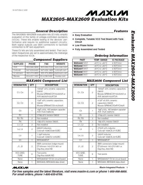
General DescriptionThe MAX2605–MAX2609 evaluation kits (EV kits) simplify evaluation of this family of voltage-controlled oscillators (VCOs). These kits enable testing of the devices’ per-formance and require no additional support circuitry.Both signal outputs use SMA connectors to facilitate connection to RF test equipment.These EV kits are fully assembled and tested. Their oscil-lation frequencies are set to approximately the midrange of the respective VCOs.Featureso Easy Evaluationo Complete, Tunable VCO Test Board with Tank Circuit o Low Phase Noiseo Fully Assembled and TestedEvaluate: MAX2605–MAX2609MAX2605–MAX2609 Evaluation Kits19-1673 Rev 0; 9/00Ordering InformationComponent SuppliersFor free samples and the latest literature, visit or phone 1-800-998-8800.For small orders, phone 1-800-835-8769.MAX2606 Component ListMAX2605 Component ListE v a l u a t e : M A X 2605–M A X 2609MAX2605–MAX2609 Evaluation Kits 2_______________________________________________________________________________________Quick StartThe MAX2605–MAX2609 evaluation kits are fully assembled and factory tested. Follow the instructions in the Connections a nd Setup section for proper device evaluation.Test Equipment Required•Low-noise power supplies (these are recommended for oscillator noise measurement). Noise or ripple will frequency-modulate the oscillator and cause spectral spreading. Batteries can be used in place of power supplies, if necessary.– Use a DC power supply capable of supplying +2.7V to +5.5V. Alternatively, use two or three 1.5V batteries.– Use a DC power supply capable of supplying +0.4V to +2.4V, continuously variable, for TUNE.Alternatively, use two 1.5V batteries with a resistive voltage divider or potentiometer.•An RF spectrum analyzer that covers the operating frequency range of the MAX2605–MAX2609• A 50Ωcoaxial cable with SMA connectors •An ammeter (optional)Connections and Setup1)Connect a DC supply (preset to +3V) to the V CC and GND terminals (through an ammeter, if desired) on the EV kit.2)Turn on the DC supply. If used, the ammeter readingMAX2607 Component ListMAX2608 Component ListEvaluate: MAX2605–MAX2609MAX2605–MAX2609 Evaluation Kits_______________________________________________________________________________________3approximates the typical operating current specified in the MAX2605–MAX2609 data sheet.3)Connect the VCO output (OUT+ or OUT-) to a spec-trum analyzer with a 50Ωcoaxial cable.4)Apply a positive variable DC voltage between 0.4V and 2.4V to TUNE.5)Check the tuning bandwidth on the spectrum analyz-er by varying the tuning voltage (+0.4V to +2.4V).Layout ConsiderationsThe EV kit PC board can serve as a guide for laying out a board using the MAX2605–MAX2609. Generally, the VCC pin on the PC board should have a decoupling capacitor placed close to the IC. This minimizes noisecoupling from the supply. Also, place the VCO as far away as possible from the noisy section of a larger sys-tem, such as a switching regulator or digital circuits.The VCO ’s performance is strongly dependent on the availability of the external tuning inductor. For best per-formance, use high-Q components and choose their val-ues carefully. To minimize the effects of parasitic ele-ments, which degrade circuit performance, place the tuning inductor and C BYP close to the VCO. For higher-frequency versions, include the parasitic PC board inductance and capacitance when calculating the oscillation frequency. In addition, remove the ground plane around and under the tuning inductor to minimize the effect of parasitic capacitance.Noise on TUNE translates into FM noise on the outputs;therefore, keep the trace between TUNE and the control circuitry as short as possible. If necessary, use an RC filter to further suppress noise, as done on the EV kits.E v a l u a t e : M A X 2605–M A X 2609MAX2605–MAX2609 Evaluation Kits 4_______________________________________________________________________________________Figure 2. MAX2608/MAX2609 EV Kits SchematicFigure 1. MAX2605/MAX2606/MAX2607 EV Kits SchematicEvaluate: MAX2605–MAX2609MAX2605–MAX2609 Evaluation Kits_______________________________________________________________________________________5Figure 3. MAX2605/MAX2606/MAX2607 EV Kits ComponentPlacement Guide—Top Silk ScreenFigure 4. MAX2608/MAX2609 EV Kits Component PlacementGuide—Top Silk ScreenFigure 5. MAX2605/MAX2606/MAX2607 EV Kits PC BoardLayout—Component SideFigure 6. MAX2608/MAX2609 EV Kits PC Board Layout—Component SideMa xim ca nnot a ssume responsibility for use of a ny circuitry other tha n circuitry entirely embodied in a Ma xim product. No circuit pa tent licenses a re implied. Maxim reserves the right to change the circuitry and specifications without notice at any time.6_____________________Maxim Integrated Products, 120 San Gabriel Drive, Sunnyvale, CA 94086 408-737-7600©2000 Maxim Integrated ProductsPrinted USAis a registered trademark of Maxim Integrated Products.E v a l u a t e : M A X 2605–M A X 2609MAX2605–MAX2609 Evaluation Kits Figure 7. MAX2605/MAX2606/MAX2607/MAX2608/MAX2609EV Kits PC Board Layout—Ground Plane。
MAX系列芯片大全

MAXIM/DALLAS 中文数据资料DS12CR887, DS12R885, DS12R887 RTC,带有恒压涓流充电器DS1870 LDMOS RF功放偏置控制器DS1921L-F5X Thermochron iButtonDS1923 温度/湿度记录仪iButton,具有8kB数据记录存储器DS1982, DS1982-F3, DS1982-F5 1k位只添加iButton?DS1990A 序列号iButtonDS1990R, DS1990R-F3, DS1990R-F5 序列号iButtonDS1991 多密钥iButtonDS2129 LVD SCSI 27线调节器DS2401 硅序列号DS2406 双通道、可编址开关与1k位存储器DS2408 1-Wire、8通道、可编址开关DS2411 硅序列号,带有VCC输入DS2413 1-Wire双通道、可编址开关DS2430A 256位1-Wire EEPROMDS2431 1024位、1-Wire EEPROMDS2480B 串行、1-Wire线驱动器,带有负荷检测DS2482-100 单通道1-Wire主控制器DS2482-100 勘误表PDF: 2482-100A2DS2482-800, DS2482S-800 八通道1-Wire主控制器DS2482-800 勘误表PDF: 2482-800A2DS2502 1k位只添加存储器DS2505 16k位只添加存储器DS28E04-100 4096位、可寻址、1-Wire EEPROM,带有PIODS3170DK DS3/E3单芯片收发器开发板DS3231, DS3231S 高精度、I2C集成RTC/TCXO/晶振DS33Z44 四路以太网映射器DS3902 双路、非易失、可变电阻器,带有用户EEPROMDS3906 三路、非易失、小步长调节可变电阻与存储器DS3984 4路冷阴极荧光灯控制器DS4302 2线、5位DAC,提供三路数字输出DS80C400-KIT DS80C400评估套件DS80C410, DS80C411 具有以太网和CAN接口的网络微控制器DS80C410 勘误表PDF: 80C410A1DS89C430, DS89C440, DS89C450 超高速闪存微控制器DS89C430 勘误表PDF: 89C430A2DS89C440 勘误表PDF: 89C440A2DS89C450 勘误表PDF: 89C450A2DS89C430 勘误表PDF: 89C430A3DS89C440 勘误表PDF: 89C440A3DS89C450 勘误表PDF: 89C450A3DS89C430 勘误表PDF: 89C430A5DS89C440 勘误表PDF: 89C440A5DS89C450 勘误表PDF: 89C450A5DS9090K 1-Wire器件评估板, B版DS9097U-009, DS9097U-E25, DS9097U-S09 通用1-Wire COM端口适配器DS9490, DS9490B, DS9490R USB至1-Wire/iButton适配器MAX1034, MAX1035 8/4通道、±VREF多量程输入、串行14位ADCMAX1072, MAX1075 1.8Msps、单电源、低功耗、真差分、10位ADCMAX1076, MAX1078 1.8Msps、单电源供电、低功耗、真差分、10位ADC,内置电压基准MAX1146, MAX1147, MAX1148, MAX1149 多通道、真差分、串行、14位ADCMAX1149EVKIT MAX1149评估板/评估系统MAX1220, MAX1257, MAX1258 12位、多通道ADC/DAC,带有FIFO、温度传感器和GPIO端口MAX1224, MAX1225 1.5Msps、单电源、低功耗、真差分、12位ADCMAX1258EVKIT MAX1057, MAX1058, MAX1257, MAX1258评估板/评估系统MAX1274, MAX1275 1.8Msps、单电源、低功耗、真差分、12位ADCMAX13000E, MAX13001E, MAX13002E, MAX13003E, MAX13004E, MAX13005E 超低电压电平转换器MAX1302, MAX1303 8/4通道、±VREF多量程输入、串行16位ADCMAX1304, MAX1305, MAX1306, MAX1308, MAX1309, MAX1310, MAX1312, MAX1313,MAX1314 8/4/2通道、12位、同时采样ADC,提供±10V、±5V或0至+5V模拟输入范围MAX13050, MAX13052, MAX13053, MAX13054 工业标准高速CAN收发器,具有±80V故障保护MAX13080E, MAX13081E, MAX13082E, MAX13083E, MAX13084E, MAX13085E, MAX13086E, MAX13087E, MAX13088E, MAX13089E +5.0V、±15kV ESD保护、失效保护、热插拔、RS-485/RS-422收发器MAX13101E, MAX13102E, MAX13103E, MAX13108E 16通道、带有缓冲的CMOS逻辑电平转换器MAX1334, MAX1335 4.5Msps/4Msps、5V/3V、双通道、真差分10位ADCMAX1336, MAX1337 6.5Msps/5.5Msps、5V/3V、双通道、真差分8位ADCMAX13481E, MAX13482E, MAX13483E ±15kV ESD保护USB收发器, 外部/内部上拉电阻MAX1350, MAX1351, MAX1352, MAX1353, MAX1354, MAX1355, MAX1356, MAX1357 双路、高端、电流检测放大器和驱动放大器MAX1450 低成本、1%精确度信号调理器,用于压阻式传感器MAX1452 低成本、精密的传感器信号调理器MAX1487, MAX481, MAX483, MAX485, MAX487, MAX488, MAX489, MAX490, MAX491 低功耗、限摆率、RS-485/RS-422收发器MAX1492, MAX1494 3位半和4位半、单片ADC,带有LCD驱动器MAX1494EVKIT MAX1493, MAX1494, MAX1495评估板/评估系统MAX1497, MAX1499 3位半和4位半、单片ADC,带有LED驱动器和μC接口MAX1499EVKIT MAX1499评估板/评估系统MAX15000, MAX15001 电流模式PWM控制器, 可调节开关频率MAX1515 低电压、内置开关、降压/DDR调节器MAX1518B TFT-LCD DC-DC转换器, 带有运算放大器MAX1533, MAX1537 高效率、5路输出、主电源控制器,用于笔记本电脑MAX1533EVKIT MAX1533评估板MAX1540A, MAX1541 双路降压型控制器,带有电感饱和保护、动态输出和线性稳压器MAX1540EVKIT MAX1540评估板MAX1551, MAX1555 SOT23、双输入、USB/AC适配器、单节Li+电池充电器MAX1553, MAX1554 高效率、40V、升压变换器,用于2至10个白光LED驱动MAX1556, MAX1557 16μA IQ、1.2A PWM降压型DC-DC转换器MAX1556EVKIT MAX1556EVKIT评估板MAX1558, MAX1558H 双路、3mm x 3mm、1.2A/可编程电流USB开关,带有自动复位功能MAX1586A, MAX1586B, MAX1586C, MAX1587A, MAX1587C 高效率、低IQ、带有动态内核的PMIC,用于PDA和智能电话MAX16801A/B, MAX16802A/B 离线式、DC-DC PWM控制器, 用于高亮度LED驱动器MAX1858A, MAX1875A, MAX1876A 双路180°异相工作的降压控制器,具有排序/预偏置启动和POR MAX1870A 升/降压Li+电池充电器MAX1870AEVKIT MAX1870A评估板MAX1874 双路输入、USB/AC适配器、1节Li+充电器,带OVP与温度调节MAX1954A 低成本、电流模式PWM降压控制器,带有折返式限流MAX1954AEVKIT MAX1954A评估板MAX19700 7.5Msps、超低功耗模拟前端MAX19700EVKIT MAX19700评估板/评估系统MAX19705 10位、7.5Msps、超低功耗模拟前端MAX19706 10位、22Msps、超低功耗模拟前端MAX19707 10位、45Msps、超低功耗模拟前端MAX19708 10位、11Msps、超低功耗模拟前端MAX2041 高线性度、1700MHz至3000MHz上变频/下变频混频器,带有LO缓冲器/开关MAX2043 1700MHz至3000MHz高线性度、低LO泄漏、基站Rx/Tx混频器MAX220, MAX222, MAX223, MAX225, MAX230, MAX231, MAX232, MAX232A, MAX233,MAX233A, MAX234, MAX235, MAX236, MAX237, MAX238, MAX239, MAX240, MAX241,MAX242, MAX243, MAX244, MAX245, MAX246, MAX247, MAX248, MAX249 +5V供电、多通道RS-232驱动器/接收器MAX2335 450MHz CDMA/OFDM LNA/混频器MAX2370 完备的、450MHz正交发送器MAX2370EVKIT MAX2370评估板MAX2980 电力线通信模拟前端收发器MAX2986 集成电力线数字收发器MAX3013 +1.2V至+3.6V、0.1μA、100Mbps、8路电平转换器MAX3205E, MAX3207E, MAX3208E 双路、四路、六路高速差分ESD保护ICMAX3301E, MAX3302E USB On-the-Go收发器与电荷泵MAX3344E, MAX3345E ±15kV ESD保护、USB收发器,UCSP封装,带有USB检测MAX3394E, MAX3395E, MAX3396E ±15kV ESD保护、大电流驱动、双/四/八通道电平转换器, 带有加速电路MAX3535E, MXL1535E +3V至+5V、提供2500VRMS隔离的RS-485/RS-422收发器,带有±15kV ESD保护MAX3570, MAX3571, MAX3573 HI-IF单芯片宽带调谐器MAX3643EVKIT MAX3643评估板MAX3645 +2.97V至+5.5V、125Mbps至200Mbps限幅放大器,带有信号丢失检测器MAX3645EVKIT MAX3645评估板MAX3654 47MHz至870MHz模拟CATV互阻放大器MAX3654EVKIT MAX3654评估板MAX3657 155Mbps低噪声互阻放大器MAX3658 622Mbps、低噪声、高增益互阻前置放大器MAX3735, MAX3735A 2.7Gbps、低功耗、SFP激光驱动器MAX3737 多速率激光驱动器,带有消光比控制MAX3737EVKIT MAX3737评估板MAX3738 155Mbps至2.7Gbps SFF/SFP激光驱动器,带有消光比控制MAX3744, MAX3745 2.7Gbps SFP互阻放大器,带有RSSIMAX3744EVKIT, MAX3745EVKIT MAX3744, MAX3745评估板MAX3748, MAX3748A, MAX3748B 紧凑的、155Mbps至4.25Gbps限幅放大器MAX3785 6.25Gbps、1.8V PC板均衡器MAX3787EVKIT MAX3787评估板MAX3793 1Gbps至4.25Gbps多速率互阻放大器,具有光电流监视器MAX3793EVKIT MAX3793评估板MAX3805 10.7Gbps自适应接收均衡器MAX3805EVKIT MAX3805评估板MAX3840 +3.3V、2.7Gbps双路2 x 2交叉点开关MAX3841 12.5Gbps CML 2 x 2交叉点开关MAX3967 270Mbps SFP LED驱动器MAX3969 200Mbps SFP限幅放大器MAX3969EVKIT MAX3969评估板MAX3982 SFP铜缆预加重驱动器MAX3983 四路铜缆信号调理器MAX3983EVKIT MAX3983评估板MAX3983SMAEVKIT MAX3983 SMA连接器评估板MAX4079 完备的音频/视频后端方案MAX4079EVKIT MAX4079评估板MAX4210, MAX4211 高端功率、电流监视器MAX4210EEVKIT MAX4210E、MAX4210A/B/C/D/F评估板MAX4211EEVKIT MAX4211A/B/C/D/E/F评估板MAX4397 用于双SCART连接器的音频/视频开关MAX4397EVKIT MAX4397评估系统/评估板MAX4411EVKIT MAX4411评估板MAX4729, MAX4730 低电压、3.5、SPDT、CMOS模拟开关MAX4754, MAX4755, MAX4756 0.5、四路SPDT开关,UCSP/QFN封装MAX4758, MAX4759 四路DPDT音频/数据开关,UCSP/QFN封装MAX4760, MAX4761 宽带、四路DPDT开关MAX4766 0.075A至1.5A、可编程限流开关MAX4772, MAX4773 200mA/500mA可选的限流开关MAX4795, MAX4796, MAX4797, MAX4798 450mA/500mA限流开关MAX4826, MAX4827, MAX4828, MAX4829, MAX4830, MAX4831 50mA/100mA限流开关, 带有空载标记, μDFN封装MAX4832, MAX4833 100mA LDO,带有限流开关MAX4834, MAX4835 250mA LDO,带有限流开关MAX4836, MAX4837 500mA LDO,带有限流开关MAX4838A, MAX4840A, MAX4842A 过压保护控制器,带有状态指示FLAGMAX4850, MAX4850H, MAX4852, MAX4852H 双路SPDT模拟开关,可处理超摆幅信号MAX4851, MAX4851H, MAX4853, MAX4853H 3.5/7四路SPST模拟开关,可处理超摆幅信号MAX4854 7四路SPST模拟开关,可处理超摆幅信号MAX4854H, MAX4854HL 四路SPST、宽带、信号线保护开关MAX4855 0.75、双路SPDT音频开关,具有集成比较器MAX4864L, MAX4865L, MAX4866L, MAX4867, MAX4865, MAX4866 过压保护控制器,具有反向保护功能MAX4880 过压保护控制器, 内置断路开关MAX4881, MAX4882, MAX4883, MAX4884 过压保护控制器, 内部限流, TDFN封装MAX4901, MAX4902, MAX4903, MAX4904, MAX4905 低RON、双路SPST/单路SPDT、无杂音切换开关, 可处理负电压MAX4906, MAX4906F, MAX4907, MAX4907F 高速/全速USB 2.0开关MAX5033 500mA、76V、高效率、MAXPower降压型DC-DC变换器MAX5042, MAX5043 双路开关电源IC,集成了功率MOSFET和热插拔控制器MAX5058, MAX5059 可并联的副边同步整流驱动器和反馈发生器控制ICMAX5058EVKIT MAX5051, MAX5058评估板MAX5062, MAX5062A, MAX5063, MAX5063A, MAX5064, MAX5064A, MAX5064B 125V/2A、高速、半桥MOSFET驱动器MAX5065, MAX5067 双相、+0.6V至+3.3V输出可并联、平均电流模式控制器MAX5070, MAX5071 高性能、单端、电流模式PWM控制器MAX5072 2.2MHz、双输出、降压或升压型转换器,带有POR和电源失效输出MAX5072EVKIT MAX5072评估板MAX5074 内置MOSFET的电源IC,用于隔离型IEEE 802.3af PD和电信电源MAX5078 4A、20ns、MOSFET驱动器MAX5084, MAX5085 65V、200mA、低静态电流线性稳压器, TDFN封装MAX5088, MAX5089 2.2MHz、2A降压型转换器, 内置高边开关MAX5094A, MAX5094B, MAX5094C, MAX5094D, MAX5095A, MAX5095B, MAX5095C 高性能、单端、电流模式PWM控制器MAX5128 128抽头、非易失、线性变化数字电位器, 采用2mm x 2mm μDFN封装MAX5417, MAX5417L, MAX5417M, MAX5417N, MAX5417P, MAX5418, MAX5419 256抽头、非易失、I2C接口、数字电位器MAX5417LEVKIT MAX5417_, MAX5418_, MAX5419_评估板/评估系统MAX5477, MAX5478, MAX5479 双路、256抽头、非易失、I2C接口、数字电位器MAX5478EVKIT MAX5477/MAX5478/MAX5479评估板/评估系统MAX5490 100k精密匹配的电阻分压器,SOT23封装MAX5527, MAX5528, MAX5529 64抽头、一次性编程、线性调节数字电位器MAX5820 双路、8位、低功耗、2线、串行电压输出DACMAX5865 超低功耗、高动态性能、40Msps模拟前端MAX5920 -48V热插拔控制器,外置RsenseMAX5921, MAX5939 -48V热插拔控制器,外置Rsense、提供较高的栅极下拉电流MAX5932 正电源、高压、热插拔控制器MAX5932EVKIT MAX5932评估板MAX5936, MAX5937 -48V热插拔控制器,可避免VIN阶跃故障,无需RSENSEMAX5940A, MAX5940B IEEE 802.3af PD接口控制器,用于以太网供电MAX5940BEVKIT MAX5940B, MAX5940D评估板MAX5941A, MAX5941B 符合IEEE 802.3af标准的以太网供电接口/PWM控制器,适用于用电设备MAX5945 四路网络电源控制器,用于网络供电MAX5945EVKIT, MAX5945EVSYS MAX5945评估板/评估系统MAX5953A, MAX5953B, MAX5953C, MAX5953D IEEE 802.3af PD接口和PWM控制器,集成功率MOSFETMAX6640 2通道温度监视器,提供双路、自动PWM风扇速度控制器MAX6640EVKIT MAX6640评估系统/评估板MAX6641 兼容于SMBus的温度监视器,带有自动PWM风扇速度控制器MAX6643, MAX6644, MAX6645 自动PWM风扇速度控制器,带有过温报警输出MAX6678 2通道温度监视器,提供双路、自动PWM风扇速度控制器和5个GPIOMAX6695, MAX6696 双路远端/本地温度传感器,带有SMBus串行接口MAX6877EVKIT MAX6877评估板MAX6950, MAX6951 串行接口、+2.7V至+5.5V、5位或8位LED显示驱动器MAX6966, MAX6967 10端口、恒流LED驱动器和输入/输出扩展器,带有PWM亮度控制MAX6968 8端口、5.5V恒流LED驱动器MAX6969 16端口、5.5V恒流LED驱动器MAX6970 8端口、36V恒流LED驱动器MAX6977 8端口、5.5V恒流LED驱动器,带有LED故障检测MAX6978 8端口、5.5V恒流LED驱动器,带有LED故障检测和看门狗MAX6980 8端口、36V恒流LED驱动器, 带有LED故障检测和看门狗MAX6981 8端口、36V恒流LED驱动器, 带有LED故障检测MAX7030 低成本、315MHz、345MHz和433.92MHz ASK收发器, 带有N分频PLLMAX7032 低成本、基于晶振的可编程ASK/FSK收发器, 带有N分频PLLMAX7317 10端口、SPI接口输入/输出扩展器,带有过压和热插入保护MAX7319 I2C端口扩展器,具有8路输入,可屏蔽瞬态检测MAX7320 I2C端口扩展器, 带有八个推挽式输出MAX7321 I2C端口扩展器,具有8个漏极开路I/O口MAX7328, MAX7329 I2C端口扩展器, 带有八个I/O口MAX7347, MAX7348, MAX7349 2线接口、低EMI键盘开关和发声控制器MAX7349EVKIT MAX7349评估板/仿真: MAX7347/MAX7348MAX7375 3引脚硅振荡器MAX7381 3引脚硅振荡器MAX7389, MAX7390 微控制器时钟发生器, 带有看门狗MAX7391 快速切换时钟发生器, 带有电源失效检测MAX7445 4通道视频重建滤波器MAX7450, MAX7451, MAX7452 视频信号调理器,带有AGC和后肩钳位MAX7452EVKIT MAX7452评估板MAX7462, MAX7463 单通道视频重建滤波器和缓冲器MAX8505 3A、1MHz、1%精确度、内置开关的降压型调节器,带有电源就绪指示MAX8524, MAX8525 2至8相VRM 10/9.1 PWM控制器,提供精密的电流分配和快速电压定位MAX8525EVKIT MAX8523, MAX8525评估板MAX8533 更小、更可靠的12V、Infiniband兼容热插拔控制器MAX8533EVKIT MAX8533评估板MAX8545, MAX8546, MAX8548 低成本、宽输入范围、降压控制器,带有折返式限流MAX8550, MAX8551 集成DDR电源方案,适用于台式机、笔记本电脑及图形卡MAX8550EVKIT MAX8550, MAX8550A, MAX8551评估板MAX8552 高速、宽输入范围、单相MOSFET驱动器MAX8553, MAX8554 4.5V至28V输入、同步PWM降压控制器,适合DDR端接和负载点应用MAX8563, MAX8564 ±1%、超低输出电压、双路或三路线性n-FET控制器MAX8564EVKIT MAX8563, MAX8564评估板MAX8566 高效、10A、PWM降压调节器, 内置开关MAX8570, MAX8571, MAX8572, MAX8573, MAX8574, MAX8575 高效LCD升压电路,可True ShutdownMAX8571EVKIT MAX8570, MAX8571, MAX8572, MAX8573, MAX8574, MAX8575评估板MAX8576, MAX8577, MAX8578, MAX8579 3V至28V输入、低成本、迟滞同步降压控制器MAX8594, MAX8594A 5路输出PMIC,提供DC-DC核电源,用于低成本PDAMAX8594EVKIT MAX8594评估板MAX8632 集成DDR电源方案,适用于台式机、笔记本电脑和图形卡MAX8632EVKIT MAX8632评估板MAX8702, MAX8703 双相MOSFET驱动器,带有温度传感器MAX8707 多相、固定频率控制器,用于AMD Hammer CPU核电源MAX8716, MAX8717, MAX8757 交叉工作、高效、双电源控制器,用于笔记本电脑MAX8716EVKIT MAX8716评估板MAX8717EVKIT MAX8717评估板MAX8718, MAX8719 高压、低功耗线性稳压器,用于笔记本电脑MAX8725EVKIT MAX8725评估板MAX8727 TFT-LCD升压型、DC-DC变换器MAX8727EVKIT MAX8727评估板MAX8729 固定频率、半桥CCFL逆变控制器MAX8729EVKIT MAX8729评估板MAX8732A, MAX8733A, MAX8734A 高效率、四路输出、主电源控制器,用于笔记本电脑MAX8737 双路、低电压线性稳压器, 外置MOSFETMAX8737EVKIT MAX8737评估板MAX8738 EEPROM可编程TFT VCOM校准器, 带有I2C接口MAX8740 TFT-LCD升压型、DC-DC变换器MAX8743 双路、高效率、降压型控制器,关断状态下提供高阻MAX8751 固定频率、全桥、CCFL逆变控制器MAX8751EVKIT MAX8751评估板MAX8752 TFT-LCD升压型、DC-DC变换器MAX8758 具有开关控制和运算放大器的升压调节器, 用于TFT LCDMAX8758EVKIT MAX8758评估板MAX8759 低成本SMBus CCFL背光控制器MAX8760 双相、Quick-PWM控制器,用于AMD Mobile Turion 64 CPU核电源MAX8764 高速、降压型控制器,带有精确的限流控制,用于笔记本电脑MAX9223, MAX9224 22位、低功耗、5MHz至10MHz串行器与解串器芯片组MAX9225, MAX9226 10位、低功耗、10MHz至20MHz串行器与解串器芯片组MAX9483, MAX9484 双输出、多模CD-RW/DVD激光二极管驱动器MAX9485 可编程音频时钟发生器MAX9485EVKIT MAX9485评估板MAX9486 8kHz参考时钟合成器,提供35.328MHz倍频输出MAX9486EVKIT MAX9486评估板MAX9489 多路输出网络时钟发生器MAX9500, MAX9501 三通道HDTV滤波器MAX9500EVKIT MAX9500评估板MAX9501EVKIT MAX9501评估板MAX9502 2.5V视频放大器, 带有重建滤波器MAX9504A, MAX9504B 3V/5V、6dB视频放大器, 可提供大电流输出MAX9701 1.3W、无需滤波、立体声D类音频功率放大器MAX9701EVKIT MAX9701评估板MAX9702 1.8W、无需滤波、立体声D类音频功率放大器和DirectDrive立体声耳机放大器MAX9702EVSYS/EVKIT MAX9702/MAX9702B评估系统/评估板MAX9703, MAX9704 10W立体声/15W单声道、无需滤波的扩展频谱D类放大器MAX9705 2.3W、超低EMI、无需滤波、D类音频放大器MAX9705BEVKIT MAX9705B评估板MAX9710EVKIT MAX9710评估板MAX9712 500mW、低EMI、无需滤波、D类音频放大器MAX9713, MAX9714 6W、无需滤波、扩频单声道/立体声D类放大器MAX9714EVKIT MAX9704, MAX9714评估板MAX9715 2.8W、低EMI、立体声、无需滤波、D类音频放大器MAX9715EVKIT MAX9715评估板MAX9716, MAX9717 低成本、单声道、1.4W BTL音频功率放大器MAX9716EVKIT MAX9716评估板MAX9718, MAX9719 低成本、单声道/立体声、1.4W差分音频功率放大器MAX9718AEVKIT MAX9718A评估板MAX9719AEVKIT MAX9719A/B/C/D评估板MAX9721 1V、固定增益、DirectDrive、立体声耳机放大器,带有关断MAX9721EVKIT MAX9721评估板MAX9722A, MAX9722B 5V、差分输入、DirectDrive、130mW立体声耳机放大器,带有关断MAX9722AEVKIT MAX9722A, MAX9722B评估板MAX9723 立体声DirectDrive耳机放大器, 具有BassMax、音量控制和I2C接口MAX9725 1V、低功率、DirectDrive、立体声耳机放大器,带有关断MAX9728AEVKIT MAX9728A/MAX9728B评估板MAX9750, MAX9751, MAX9755 2.6W立体声音频功放和DirectDrive耳机放大器MAX9759 3.2W、高效、低EMI、无需滤波、D类音频放大器MAX9759EVKIT MAX9759评估板MAX9770, MAX9772 1.2W、低EMI、无需虑波、单声道D类放大器,带有立体声DirectDrive耳机放大器MAX9787 2.2W立体声音频功率放大器, 提供模拟音量控制MAX9850 立体声音频DAC,带有DirectDrive耳机放大器MAX9890 音频咔嗒声-怦然声抑制器MAX9951, MAX9952 双路引脚参数测量单元MAX9960 双闪存引脚电子测量/高压开关矩阵MAX9961, MAX9962 双通道、低功耗、500Mbps ATE驱动器/比较器,带有2mA负载MAX9967 双通道、低功耗、500Mbps ATE驱动器/比较器,带有35mA负载MAX9986A SiGe高线性度、815MHz至1000MHz下变频混频器, 带有LO缓冲器/开关MAXQ2000 低功耗LCD微控制器MAXQ2000 勘误表PDF: MAXQ2000A2MAXQ2000-KIT MAXQ2000评估板MAXQ3120-KIT MAXQ3120评估板MXL1543B +5V、多协议、3Tx/3Rx、软件可选的时钟/数据收发器。
科尔摩根AKM 同步伺服电机 选型指南说明书
K O L L M O R G E N | A K o l l m o r g e n C O M PA N Y欢迎来到科尔摩根官方微信科尔摩根3目录u AKM ™ 同步伺服电机4u AKD ™ 伺服驱动器8u AKM ™ 各种选件12u AKM ™ 防水型和食品级防水型电机13u AKM ™ 系统综述14u AKM ™ 图纸和性能数据AKM1x 16AKM2x 20AKM3x24AKM4x 28AKM5x 34AKM6x 40AKM7x 44AKM8x48u L 10 轴承疲劳寿命和轴负载53u 反馈选件56u 抱闸选件60u 伺服电机连接器选件61u 型号命名67u MOTIONEERING ® Online71科尔摩根A K M 同步伺服电机选型指南克服设计、采购和时间障碍科尔摩根明白:帮助原始设备制造商的工程师克服障碍,可以显著提高其工作成效。
因而,我们主要通过如下三种方式来提供帮助:集成标准和定制产品在很多情况下,理想方案都不是一成不变的。
我们拥有专业应用知识,可以根据全面的产品组合来修改标准产品或开发全定制解决方案,从而为设计奠定良好的基础。
提供运动控制解决方案而不仅仅是部件在各公司减少供应商数量和工程人力的过程中,他们需要一家能够提供多种集成解决方案的全系统供应商。
科尔摩根就采用了全面响应模式,为客户提供全套解决方案,这些方案将编程软件、工程服务以及同类优秀的运动控制部件结合起来。
覆盖全球我们在美洲、欧洲、中东和亚洲拥有众多直销、工程支持单位、生产工厂以及分销商,临近全球各地的原始设备制造商。
这种便利优势可以加速我们的供货过程,根据客户需要随时随地供货。
财务和运营稳定性科尔摩根隶属于Fortive 公司。
Fortive 业务系统是推动Fortive 各部门发展的一个关键力量。
该系统采用“不断改善”(Kaizen )原理。
由高素质人才构成的多学科团队使用世界级的工具对过程进行评估,并制定相关计划以达到卓越的性能。
MAX913中文资料
M A X912/M A X913————单/双路,超高速,低功耗,精密的TTL比较器1.总体描述MAX913(单)和MAX912(双)高速,低功耗比较器是一个拥有独特设计就是在其线性区域是它的比较是可以防止振荡。
没有要求最低输入转换率。
它是由差分输入和互补的TTL输出。
快速传播延迟(10ns的典型值),具有极低的电源电流和宽共模输入范围,包括负电流使MAX912/MAX913达到的低功耗理想效果,高速,单电源+5V(或±5V)的应用,例如有V/F转换器和开关稳压器。
MAX912/MAX913保持着稳定的线性区域输出。
此功能消除了常见的在输出不稳定时产生高速驱动时具有的比较滞销输入信号。
该MAX912/MAX913可以单一+5V电源供电或±5V的分别供应。
该MAX913是一个改进的LT1016的替代品。
在输入一小能量时它提供了更宽的输入电压范围和等效速度。
在MAX912双比较具有同等性能的MAX913并且包括独立的锁存控制功能。
2.应用过零检测器以太网线接收器开关稳压器高速采样电路高速触发器扩展范围的V/F转换器快速脉冲宽度/高度的判别3.特点超快速(为10ns)单+5V或±5V的双电源供电输入范围扩展至负电源以下低功耗:6毫安(+5V)的每次比较无最小输入信号摆率的要求无电源电流扣球稳定的线性区可投入任一电源低失调电压:0.8mV4.引脚配置顶视图:5.绝对最大额定值:正电源电压 (7V)负电源电压..............................................-7V差分输入电压.......................................±15V输入电压....................................-0.3V至15V锁存引脚电压...................................等于耗材连续输出电流.....................................±20mA连续功耗(TA=70℃)8引脚塑料DIP(减少9.09mW/妹高于70°)......727mW 8引脚SO(减少5.88mW/每高于70°).................471mW 8引脚CERDIP(减少8.00mW/每高于70°).........640mW 16引脚塑料DIP(减少10.53mW/高于70°).......842mW 16引脚窄的SO(减免8.70mW/高于70°)..........696mW16引脚CERDIP(减免10.00mW/高于70°)..........800mW工作温度范围:MAX91C......................................................0℃至70℃MAX91E....................................................-40℃至85℃MAX91MJ.................................................-55℃至125℃储存温度范围........................................-65°C至150°C焊接温度(10秒).........................................................300℃注:超越“绝对最大额定值“,即可能造成永久性损坏设备。
Maxstar 161 S 电缆焊接机说明书
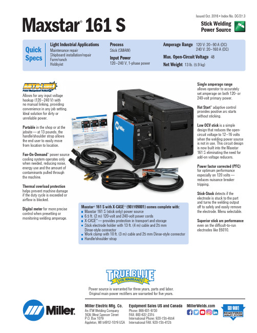
Issued Oct. 2016 • Index No. DC/27.3Single amperage range allows operator to accurately set amperage on both 120- or 240-volt primary power.Hot Start ™adaptive control provides positive arc starts without sticking.Low OCV stick is a simple design that reduces the open-circuit voltage to 12–16 volts when the welding power source is not in use. This circuit design is now built into the Maxstar 161 S eliminating the need for add-on voltage reducers.Power factor corrected (PFC)for optimum performance especially on 120 volts —reduces nuisance breaker tripping.Stick-Stuck detects if the electrode is stuck to the part and turns the welding output off to safely and easily remove the electrode. Menu selectable.Superior stick arc performance even on the difficult-to-run electrodes like E6010.Maxstar ®161 S with X-CASE ™(907709001) comes complete with:Maxstar 161 S (stick only) power source6.5 ft. (2 m) 120-volt and 240-volt power cordsX-CASE ™—provides protection in transport and storage Stick electrode holder with 13 ft. (4 m) cable and 25 mm Dinse-style connectorWork clamp with 10 ft. (3 m) cable and 25 mm Dinse-style connector Handle/shoulder strapPower source is warranted for three years, parts and labor.Original main power rectifiers are warranted for five years.Allows for any input voltage hookup (120–240 V) with no manual linking, providing convenience in any job setting.Ideal solution for dirty or unreliable power.Portable in the shop or at the jobsite —at 13 pounds, the handle/shoulder strap allows the end user to easily move from location to location.Fan-On-Demand ™power source cooling system operates only when needed, reducing noise,energy use and the amount of contaminants pulled through the machine.Thermal overload protection helps prevent machine damage if the duty cycle is exceeded or airflow is blocked.Digital meter for more precise control when presetting or monitoring welding amperage.Maxstar ®161SStick Welding Power SourceMiller Electric Mfg. Co.An ITW Welding Company 1635 West Spencer Street P.O. Box 1079Appleton, WI 54912-1079 USAEquipment Sales US and Canada Phone: 866-931-9730FAX: 800-637-2315International Phone: 920-735-4554International FAX: 920-735-4125Power Source and Options Stock No.DescriptionQty.PriceMaxstar ®161 S (only)907709Includes electrode holder, work clamp, and 120-volt and 240-volt power cords Maxstar ®161 S with X-CASE ™907709001Includes 907709 plus X-CASE ™Accessories X-CASE ™(only)301429Carrying case for Maxstar 161Date:Total Quoted Price:Ordering InformationControl PanelCertified by Canadian Standards Association to both the Canadian and U.S. Standards.1. Power Switch2.Menu Button3. Positive Weld Output Receptacle4.Ready Light5.Amperage Adjustment Control6.Negative Weld Output Receptacle*Sense voltage for stick.©2016 Miller Electric Mfg. Co.Distributed by:。
Connect Tech XMC to PCIe 104 Adapter 用户指南说明书

XMC to PCIe/104 AdapterConnect Tech Inc.Tel:519-836-129142 Arrow Road Toll:800-426-8979 (North America only) Guelph, Ontario Fax:519-836-4878N1K 1S6 Email:********************************************Table of ContentsTable of Contents (2)Preface (3)Disclaimer (3)Customer Support Overview (3)Contact Information (3)Limited Product Warranty (4)Copyright Notice (4)Trademark Acknowledgment (4)ESD Warning (5)Revision History (5)Introduction (6)Product Features and Specifications (6)Product Overview (7)Connector Summary & Locations (7)Jumper Summary & Locations (8)Detailed Feature Description (9)PCIe/104 Connector (9)Description (9)Connectors & Jumpers (9)XMC Expansion Slot (10)Description (10)Connectors & Jumpers (10)Indicator LEDs (11)Description (11)Connectors & Jumpers (11)Typical Installation (12)PrefaceDisclaimerThe information contained within this user’s guide, including but not limited to any product specification, is subject to change without notice.Connect Tech assumes no liability for any damages incurred directly or indirectly from any technical ortypographical errors or omissions contained herein or for discrepancies between the product and the user’s guide.Customer Support OverviewIf you experience difficulties after reading the manual and/or using the product, contact the Connect Tech reseller from which you purchased the product. In most cases the reseller can help you with product installation and difficulties.In the event that the reseller is unable to resolve your problem, our highly qualified support staff can assist you.Our support section is available 24 hours a day, 7 days a week on our website at:/sub/support/support.asp. See the contact information section below for moreinformation on how to contact us directly. Our technical support is always free.Contact InformationMail/CourierConnect Tech Inc.Technical Support42 Arrow RoadGuelph, OntarioCanada N1K 1S6Email/Internet********************************************Telephone/FacsimileTechnical Support representatives are ready to answer your call Monday through Friday, from 8:30 a.m. to 5:00 p.m. Eastern Standard Time. Our numbers for calls are:Toll Free: 800-426-8979 (North America only)Telephone: 519-836-1291 (Live assistance available 8:30 a.m. to 5:00 p.m. EST,Monday to Friday)Facsimile: 519-836-4878 (on-line 24 hours)Limited Product WarrantyConnect Tech Inc. provides a 2 year Warranty for the XMC to PCIe/104 Adapter. Should this product, in Connect Tech Inc.'s opinion, fail to be in good working order during the warranty period, Connect Tech Inc.will, at its option, repair or replace this product at no charge, provided that the product has not been subjected to abuse, misuse, accident, disaster or non-Connect Tech Inc. authorized modification or repair.You may obtain warranty service by delivering this product to an authorized Connect Tech Inc. business partner or to Connect Tech Inc. along with proof of purchase. Product returned to Connect Tech Inc. must be pre-authorized by Connect Tech Inc. with an RMA (Return Material Authorization) number marked on the outside of the package and sent prepaid, insured and packaged for safe shipment. Connect Tech Inc. will return this product by prepaid ground shipment service.The Connect Tech Inc. Limited Warranty is only valid over the serviceable life of the product. This is defined as the period during which all components are available. Should the product prove to be irreparable, Connect Tech Inc. reserves the right to substitute an equivalent product if available or to retract the Warranty if no replacement is available.The above warranty is the only warranty authorized by Connect Tech Inc. Under no circumstances willConnect Tech Inc. be liable in any way for any damages, including any lost profits, lost savings or otherincidental or consequential damages arising out of the use of, or inability to use, such product. Copyright NoticeThe information contained in this document is subject to change without notice. Connect Tech Inc. shall not be liable for errors contained herein or for incidental consequential damages in connection with the furnishing, performance, or use of this material. This document contains proprietary information that is protected by copyright. All rights are reserved. No part of this document may be photocopied, reproduced, or translated to another language without the prior written consent of Connect Tech, Inc.Copyright 2016 by Connect Tech, Inc.Trademark AcknowledgmentConnect Tech, Inc. acknowledges all trademarks, registered trademarks and/or copyrights referred to in this document as the property of their respective owners. Not listing all possible trademarks or copyrightacknowledgments does not constitute a lack of acknowledgment to the rightful owners of the trademarks and copyrights mentioned in this document.ESD WarningElectronic components and circuits are sensitive toElectroStatic Discharge (ESD). When handling any circuit board assemblies including Connect Tech COM Express carrier assemblies, it is recommended that ESD safety precautions be observed. ESD safe best practices include, but are not limited to:∙ Leaving circuit boards in their antistatic packaginguntil they are ready to be installed.∙ Using a grounded wrist strap when handling circuitboards, at a minimum you should touch a grounded metal object to dissipate any static charge that may be present on you.∙ Only handling circuit boards in ESD safe areas, whichmay include ESD floor and table mats, wrist strap stations and ESD safe lab coats.∙ Avoiding handling circuit boards in carpeted areas. ∙ Try to handle the board by the edges, avoiding contactwith components.Revision HistoryIntroductionConnect Tech’s XMC to PCIe/104 Adapter Board is an engineering tool for the purpose of enabling rapid development of systems requiring the use of next generation form factor peripheral cards. This product complies with the VITA 42 specification.Product Features and SpecificationsProduct Overview Connector Summary & Locations ADG095 Top ViewADG095 BottomViewJumper Summary & LocationsDetailed Feature DescriptionPCIe/104 ConnectorDescriptionPCIe/104 interface to CPU module Connectors & JumpersXMC Expansion SlotDescriptionM.2 interface slots for expansion cards. Can be ordered in either key E or key BM. Card type support is listed below.See Part Numbers/Ordering Information section for more ordering details.Connectors & JumpersIndicator LEDsDescriptionIndicator LED’s Connectors & JumpersTypical InstallationCard may be installed in a stack-up or stack-down configuration. 10mm height, M2.5 standoffs required between XMC adapter and XMC expansion card. Example stack-up on Connect Tech’s Com Express Type 6 104e Carrier shown below:。
MAX999EUK-T中文资料
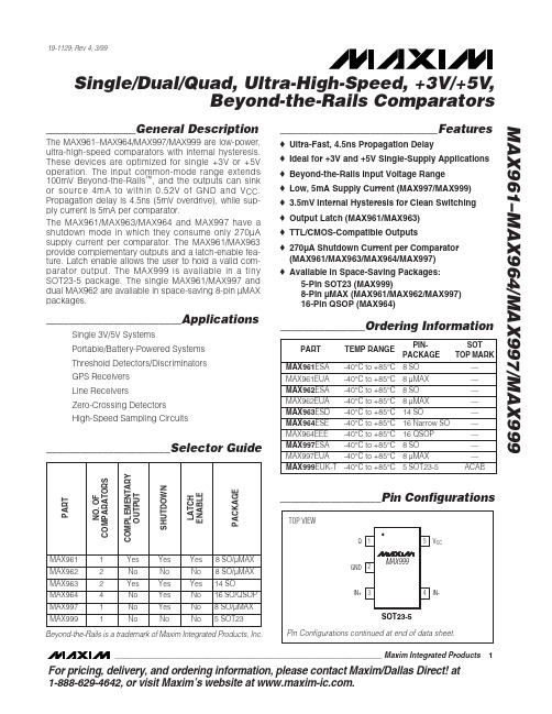
TOP VIEW
Q1 GND 2
MAX999
5 VCC
IN+ 3
4 IN-
SOT23-5 Pin Configurations continued at end of data sheet.
________________________________________________________________ Maxim Integrated Products 1
— — — — — — — — ACAB
PART NO. OF COMPARATORS COMPLEMENTARY OUTPUT SHUTDOWN LATCH ENABLE PACKAGE
__________________Pin Configurations
MAX961
1
MAX962
2
MAX963
PART
TEMP RANGE
PINPACKAGE
SOT TOP MARK
MAX961ESA -40°C to +85°C 8 SO
—
MAX961EUA MAX962ESA MAX962EUA MAX963ESD MAX964ESE MAX964EEE MAX997ESA MAX997EUA MAX999EUK-T
2
MAX964
4
MAX997
1
MAX999
1
Yes Yes Yes 8 SO/µMAX
No
No
No 8 SO/µMAX
Yes Yes Yes 14 SO
No
Yes
No 16 SO/QSOP
No
Yes
No 8 SO/µMAX
No
MAX809(复位芯片)
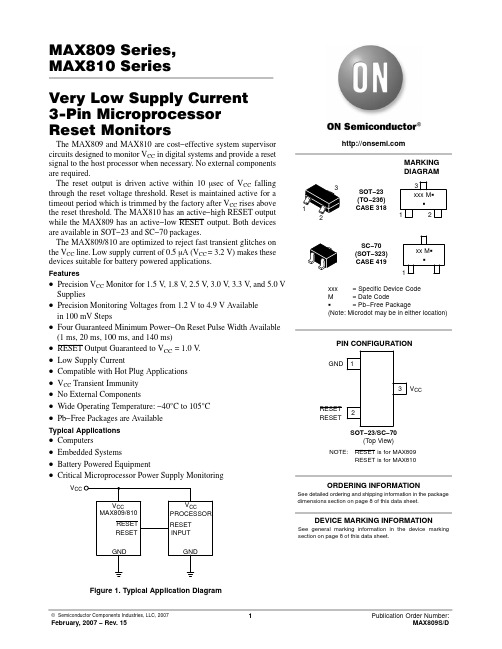
3
VCC
Description
Ground
RESET output remains low while VCC is below the reset voltage threshold, and for a reset timeout period after VCC rises above reset threshold
RESET output remains high while VCC is below the reset voltage threshold, and for a reset timeout period after VCC rises above reset threshold
Supply Voltage (Typ)
Typical Applications
• Computers • Embedded Systems • Battery Powered Equipment • Critical Microprocessor Power Supply Monitoring
VCC
VCC MAX809/810
RESET RESET
ORDERING INFORMATION
See detailed ordering and shipping information in the package dimensions section on page 8 of this data sheet.
DEVICE MARKING INFORMATION
VCC PROCESSOR
RESET INPUT
GND
GND
3
1 2
SOT−23 (TO−236) CASE 318
MAX9926UAEE+中文资料
16-Pin QSOP ................................................................37°C/W
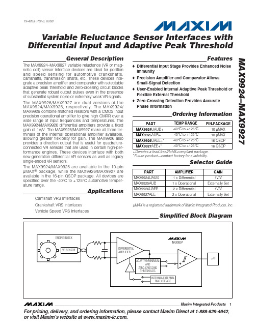
The MAX9926/MAX9927 are dual versions of the MAX9924/MAX9925, respectively. The MAX9924/ MAX9926 combine matched resistors with a CMOS input precision operational amplifier to give high CMRR over a wide range of input frequencies and temperatures. The MAX9924/MAX9926 differential amplifiers provide a fixed gain of 1V/V. The MAX9925/MAX9927 make all three terminals of the internal operational amplifier available, allowing greater flexibility for gain. The MAX9926 also provides a direction output that is useful for quadratureconnected VR sensors that are used in certain high-performance engines. These devices interface with both new-generation differential VR sensors as well as legacy single-ended VR sensors.
科尼卡自动风卷器F - 科尼卡FC-1系统说明书

143KN980
'Specifications subject to change Without notice
Konica Division BERKEY MARKETING COMPANIES
Frame Speed . .. .. .. .. .. ..... ... 1.5 frames Байду номын сангаасer second
Shutter Speed Coupling Range ... . ... All shutter speeds 2 seconds to 1/1000 second.
Operation Indicator . .... . . . .. ... .. LED lights when film is being advanced.
Key Features
• Provides fully automatic 10ac1lng for the Konica FC-1 System. Drop the film cass~te into the Konlca FC-1, extend the leader and clo$8 the back. The Konlca Autowinder will automatically advance the film to frame NO.1.
End of Film Indicator . . ...... ........ LED remains on to indicate end of roll.
Film Loading Automatically advances film to frame NO.1 .
9610中文操作手册
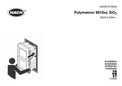
机械安装 危险
受伤或死亡风险。确保墙式安装能够承受设备 4 倍的重量。
78 中文
图 3 单样品流或双样品流端口
图 4 四样品流端口
1 未使用 2 样品 4 旁通排放口 1 排液通气口 - 保持打 开 2 未使用 3 仅限双样品流分析仪: 样品 2 旁通排放口 4 空气吹扫入口(可选) 7 壳体排放口(排放溅出 或泄漏液) 5 样品 1 旁通排放口 6 化学品排放口 8 样品 1 入口 9 仅限双样品流分析仪: 样品 2 入口 3 样品 3 旁通排放口
DOC023.97.80246
Polymetron 9610sc SiO2
05/2013, Edition 1
Installation Installation Instalación Instalação 安装 設置 설치
การติดตั้ง
目录
规格 第 74 基本信息 第 75 安装 第 78 警报继电器输出 规格 4–20 mA 输出端
警告标签
请阅读贴在仪器上的所有标签和标记。如未遵照这些安全标签的指示操 作,则可能造成人身伤害或仪器损坏。仪器上如有标志,则手册中会提供 危险或小心说明。
中文 75
这是安全警报标志。请遵守此标志后面的所有安全信息,以避免可能造 成的伤害。如果仪器上有此标志,则请参见仪器手册,了解操作或安全 信息。 此标志指示需要戴上防护眼镜。
1
规格
产品规格如有变化,恕不另行通知。 表 1 一般技术指标
规格 详细信息 保险丝
尺寸(宽 x 深 x 高) 452 x 360 x 804 mm (17.8 x 14.2 x 31.7 in.) 外壳 防护等级:NEMA 4x/IP65 材料:PC/ABS 壳体,PC 门,PC 铰链和锁,316 SST 五金 件 仅限室内使用。避免阳光直射。 重量 安装 保护等级 污染程度/安装类别 电源要求 不含试剂和标准液时:20 kg (45 lb),含试剂时:36.3 kg (80 lb) 璧装式、板装式或台式 I 2/II 交流电:100–240 VAC,50/60 Hz 仪器:标称 0.5 A,最大 2.6 A 连接:18 至 16 号 AWG 接线,推荐使用 18 号 AWG 绞合线 工作温度 工作湿度 存储温度 最大高度 5 至 45°C(41 至 113 °F) 5 至 95% 非冷凝 –20 至 60 °C (–4 至 140 °F) 2000 m (6560 ft)
Xilinx Kintex UltraScale FPGA KCU105 评估板及高速模拟数据接口开

HARDWARE-Xilinx Kintex UltraScale FPGA KCU105 Evaluation Board-Kintex XCKU040-2FFVA1156E Device-Analog Devices AD-FMCDAQ2-EBZ FMC Module -AD9680 Dual 14-Bit, 1.0 GSPS, JESD204B A/D Converter-AD9144 Quad 16-Bit, 2.8 GSPS JESD204B Transmit D/A Converter -2 SMA RF coax cables -USB A-to-micro-B Cables (2) -Ethernet Cable -12 V power supply TARGET APPLICATIONS-Wideband data acquisition over JESD204B -Test and measurement equipment -Radar and advanced imaging -CMTS and Cable Access -Military / aerospaceThe Xilinx Kintex ® UltraScale ™ FPGA DSP Development Kitwith JESD204B High-Speed Analog provides a comprehensive platform for rapid prototyping of high performance digital signal processing applications with wideband analog data acquisition. High-level design methodologies, IP , and verifi ed reference designs are also included to accelerate development. The system combines the Xilinx KCU105 evaluation board featuring the Kintex UltraScale XCKU040 FPGA, with the Analog Devices AD-FMCDAQ2 high-speed analog FMC card, enabling wideband data acquisition over JESD204B high-speed serial connectivity through the GTH gigabit transceivers of the Kintex UltraScale FPGA. Data acquisition is managed under Ubuntu Linux running on a MicroBlaze soft processor within the FPGA, supporting fast data exchange over Ethernet to Analog Devices IIO Oscilloscope and MATLAB and Simulink. With a complete JESD204B wideband data acquisition system ready to use out of the box, you can focus your development efforts on adding differentiating features to your system.FEATURES-Xilinx Kintex UltraScale FPGA KCU105 Evaluation Board -Analog Devices AD-FMCDAQ2-EBZ High-speed Analog FMC Module with JESD204B -Xilinx LogiCORE ™ IP JESD204B includedSOFTWARE TOOLS-Xilinx Vivado ® Design Suite: System Edition (device-locked to Kintex UltraScale XCKU040)-Includes Xilinx System Generator for DSP -Xilinx LogiCORE ™IP JESD204B-Analog Devices IIO System Object for data streaming to MATLAB & Simulink over EthernetTo purchase this kit, visit/us/kusdspkitXilinx Kintex ® UltraScale ™FPGA DSP Development Kit withJESD204B High-Speed AnalogFEATURED MANUFACTURERSBLOCK DIAGRAMAsia151 Lorong Chuan#06-03 New Tech Park Singapore 556741********************+65-6580-6000North America 2211 S 47th StreetPhoenix, Arizona 85034United States of America *******************1-800-585-1602CONTACT INFORMATIONJapanYebisu Garden Place Tower, 23F 4-20-3 Ebisu, Shibuya-ku Tokyo 150-6023 Japan **********************+81-(0)3-5792-8210EuropeGruber Str. 60c 85586 Poing Germany********************+49-8121-77702Copyright © 2017 Avnet, Inc. AVNET, "Reach Further," and the AV logo are registered trademarks of Avnet, Inc. All other brands are the property of their respective owners.LIT# 5094-PB-AES-KCU-JESD-G-V1。
Maxim推出高精度、微型电流检测放大器MAX9610

Maxim推出高精度、微型电流检测放大器MAX9610
佚名
【期刊名称】《电子制作》
【年(卷),期】2009(000)004
【摘要】MAX9610专为电池供电设备而设计。
采用精密的输入级实现1.6—5.5V的输入共模电压范围(电池电压)。
该输入范围非常适合检测单节锂离子(Li+)电池的电流,这种电池充满时电压为4.2V,正常使用时为3.6V,电压低于2.9V时将再次进行充电。
此外,MAX9610的1μA超低电源电流.延长了电池使用时间;500μV(最大值)的VOS和±0.5%(最大值)的增益误差大大提高了检测精度。
该高精度器件提供微型μDFN和SC70封装,
【总页数】1页(P4)
【正文语种】中文
【中图分类】TN722
【相关文献】
1.一种用于高端电流检测的高精度放大器的设计 [J], 杨旸;吴晓波
2.Maxim推出小尺寸高精度电流检测放大器 [J],
3.安森美半导体推出新型多媒体模拟音频开关和高精度电流检测放大器 [J],
4.Maxim推出微型汽车检流放大器 [J],
5.Maxim推出1mm^2高精度电流检测放大器 [J],
因版权原因,仅展示原文概要,查看原文内容请购买。
