SMC电磁阀SY9140R-5DZ说明书
SMC电气比例阀说明书

产品名称:SMC电气比例阀说明书
阀对流量的控制可以分为两种:
一种是开关控制:要么全开、要么全关,流量要么最大、要么最小,没有中间状态,如普通的电磁直通阀、电磁换向阀、电液换向阀。
另一种是连续控制:阀口可以根据需要打开任意一个开度,由此控制通过流量的大小,这类阀有手动控制的,如节流阀,也有电控的,如比例阀、伺服阀。
所以使用比例阀或伺服阀的目的就是:以电控方式实现对流量的节流控制(当然经过结构上的改动也可实现压力控制等),既然是节流控制,就必然有能量损失,伺服阀和其它阀不同的是,它的能量损失更大一些,因为它需要一定的流量来维持前置级控制油路的工作。
SMC比例阀中文说明书
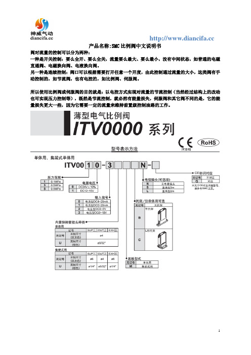
产品名称:SMC比例阀中文说明书
阀对流量的控制可以分为两种:
一种是开关控制:要么全开、要么全关,流量要么最大、要么最小,没有中间状态,如普通的电磁直通阀、电磁换向阀、电液换向阀。
另一种是连续控制:阀口可以根据需要打开任意一个开度,由此控制通过流量的大小,这类阀有手动控制的,如节流阀,也有电控的,如比例阀、伺服阀。
所以使用比例阀或伺服阀的目的就是:以电控方式实现对流量的节流控制(当然经过结构上的改动也可实现压力控制等),既然是节流控制,就必然有能量损失,伺服阀和其它阀不同的是,它的能量损失更大一些,因为它需要一定的流量来维持前置级控制油路的工作。
SMC系列产品使用说明书
5.3对于1-PC和牙嵌式驱动空心轴的电动装置其安装方法是:起吊电动装置使1-PC空心轴孔与阀杆和键配合装入,牙嵌驱式空心轴上的牙嵌与阀门上阀杆螺母的牙嵌对准。用螺栓将电动装置与阀门紧固可靠。
4.1专用电动机:适合阀门的载荷特性和使用工况,型号YLT。
4.2减速机构:用于传递和增大电动机的动力。每个机座产品均有3~5种速比的蜗轮副和若干电机齿轮与蜗杆轴齿轮传动比的齿轮副,因而可获得较大的输出转速范围。
4.3驱动空心轴:它是电动装置的动力输出部件,有2-PC、1-PC、牙嵌式三种型式,结构可见(图10)~(图12)
2.基本技术参数
产品符合JB/T8528-1997《普通型阀门电动装置技术条件》
2.1动力电源:380V、50Hz三相正弦交流电(根据用户要求,某些规格可提供使用单相220V电源的电动机)。
2.2外壳防护等级:SMC-04、03 IP67
SMC-00~5 IP65
2.3使用环境温度:-20℃~40℃;-20℃~60℃(根据用户订货要求)
G·L·SW各列转体上触点的相对位置可任意布置,即同一列上的触点可以全部为“OFF”型式或为“OFF”“ON”两种型式。(最常用的是“OFF”“ON”的布置型式)。
G·L·SW中间的两列转体触点开关可做为阀门某两个中间位置的信号输出,也可将其调整到与两边的转体同步动作。
(图17)为典型控制原理时触点开关的布置型式。
电气接线程序及注意事项:
7.1确认电源电压与电动机使用电压相同。
电磁阀说明书

电磁阀说明书电磁阀说明书1. 简介电磁阀是一种常见的控制装置,通过电磁力作用来控制介质(例如液体、气体或气体)的流动。
电磁阀广泛应用于各种工业领域,例如液压系统、气动系统、冷却系统等。
本说明书旨在介绍电磁阀的工作原理、结构、安装和使用方法。
2. 工作原理电磁阀是由电磁线圈和阀体组成的。
电磁线圈通过通电产生磁场,使阀体内的阀芯移动,从而开启或关闭阀门。
在通电或断电状态下,电磁阀起到控制介质流动的作用。
当线圈通电时,磁场吸引阀芯,使阀门打开;当线圈断电时,阀芯弹簧恢复原位,阀门关闭。
3. 结构电磁阀主要由以下几个部分组成:- 阀体:包含阀门和管道接口,用于控制介质的流动。
- 阀芯:位于阀体内,受到电磁力控制,用于打开或关闭阀门。
- 电磁线圈:位于阀体外侧,通过通电产生磁场,控制阀芯的移动。
- 弹簧:用于恢复阀芯原位,关闭阀门。
- 密封件:防止介质泄漏,保证阀门的密封性能。
4. 安装方法在安装电磁阀时,需要注意以下几点:1. 选择合适的阀门类型和规格,根据实际需要确定。
2. 确保安装位置符合要求,避免电磁阀受到外力干扰或介质堵塞。
3. 注意阀门的进出口方向,确保介质能够顺利流动。
4. 连接接口要牢固可靠,确保不会发生泄漏。
5. 注意接线的正确性,防止电磁阀工作异常。
5. 使用方法电磁阀使用时需要注意以下几点:1. 确保电源的正常供应,电压和频率要与电磁阀的标定值相匹配。
2. 操作开关或控制装置,控制电磁阀的通电和断电。
3. 注意使用环境温度,避免过高或过低的温度对电磁阀的影响。
4. 定期检查电磁阀的工作状态,确保正常运行。
5. 当电磁阀长时间不使用时,应断开电源,并进行必要的维护。
6. 注意事项在使用电磁阀时,需要特别注意以下事项:1. 严禁在电磁阀上进行改装或修理,以免造成故障或危险。
2. 禁止超负荷使用电磁阀,确保电磁阀在额定压力和温度下正常工作。
3. 当电磁阀出现异常情况(如漏电、发热等)时,应立即停止使用,并寻求专业人士的帮助。
SMC说明书
SM-14S M C系列阀门电动装置使 用 说 明 书天津百利二通机械有限公司TIANJIN BAILI ERTONG MACHINERY CO.,LTD.目 录第一部分 SMC系列普通型产品使用说明第二部分 SMC系列整体型产品使用说明第三部分 SMC系列隔爆型产品使用说明第四部分 SMC-04~SMC-2低温型产品使用说明第一部分 SMC系列普通型产品使用说明1.概述SMC系列多回转型阀门电动装置(以下称电动装置)用于驱动控制阀瓣作直线运动的闸阀、截止阀、隔膜阀等多回转阀门。
SMC系列中的部分机座产品也可以同BA伞齿轮减速器或直齿轮减速器组合,形成SMC/BA等组合式多回转电动装置。
当SMC系列产品与HBC蜗轮减速器或JA行星减速器组合后则成为组合式部分回转电动装置,它用于驱动控制阀瓣作旋转运动的球阀、蝶阀、旋塞阀等部分回转阀门。
SMC系列电动装置可以远距离电动操作(控制室内操作),可以根据订货要求加装现场按钮灯盒,从而具备现场操作功能。
SMC系列产品的手动机构可完成现场手动操作阀门。
由于SMC/BA、SMC/HBC、SMC/JA等组合型式电动装置的控制、调节部件均在SMC系列产品上,所以本说明书同样适用于上述产品。
(图1)~(图9)所示为SMC、SMC/BA、SMC/HBC、SMC/JA普通型产品的外形主视图。
上述产品的外形和法兰连接尺寸可参见我公司有关产品样本。
所用电动装置的输出转矩、转速、转圈数、电动机功率等详见该电动装置的铭牌。
2.基本技术参数产品符合GB/T24923-2010《普通型阀门电动装置技术条件》2.1动力电源:380V、50Hz(特殊订货可提供220V、415 V、440 V、460 V、480 V、660 V、690 V,50Hz、60Hz)三项正弦交流电(根据用户要求,某些规格可提供单相220V电源的电动机)。
2.2外壳保护等级:IP65~IP67(IP68订货时提出)2.3使用环境温度:-20℃~70℃(根据用户订货要求)2.4环境相对湿度:≤90%(25℃时)2.5海拔高度:≤1000m2.6短时工作:时间定额为10、15、30min(根据电动机负载情况而定)2.7无强烈振动工况。
SMC SY 系列 电磁阀 说明书

文件No.SY3000∗-OMH0002电磁阀SY系列(搭载V100先导阀)安全上的注意事项 --------------------------------------------------------------------------------------2,3设计上的注意事项 -------------------------------------------------------------------------------------- 4,5 选定 ---------------------------------------------------------------------------------------------------------4,5安装 -------------------------------------------------------------------------------------------------------- 6配管 -------------------------------------------------------------------------------------------------------- 6配线 -------------------------------------------------------------------------------------------------------- 6润滑 -------------------------------------------------------------------------------------------------------- 6气源 --------------------------------------------------------------------------------------------------------7使用环境-----------------------------------------------------------------------------------------------7维护点检-----------------------------------------------------------------------------------------------7产品个别注意事项 ---------------------------------------------------------------------------------------- 8~14 故障及应对方法 -------------------------------------------------------------------------------------------15,16URL ㊟对本使用说明书进行的变动不另行通知,请谅解。
smc气动比例阀中文说明书
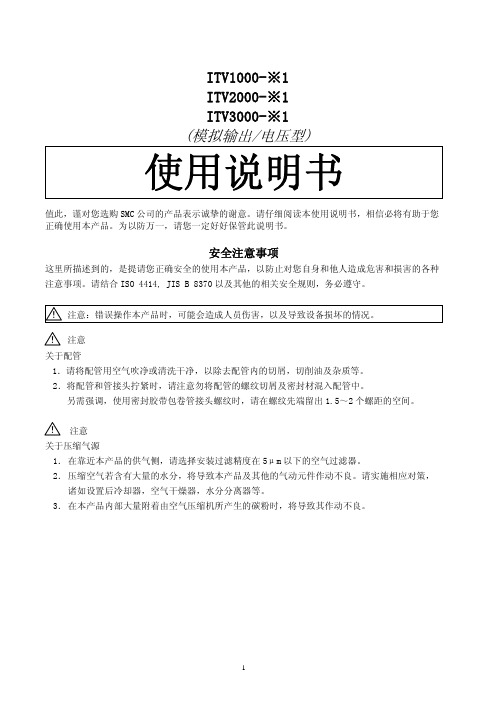
关于压缩气源 1. 在靠近本产品的供气侧,请选择安装过滤精度在 5μm 以下的空气过滤器。 2. 压缩空气若含有大量的水分,将导致本产品及其他的气动元件作动不良。请实施相应对策, 诸如设置后冷却器,空气干燥器,水分分离器等。 3. 在本产品内部大量附着由空气压缩机所产生的碳粉时,将导致其作动不良。
显示用 LED
键锁定的解除方法 ▽键持续按 2 秒以上,显示用 LED 中“ ”的字样交替闪灭。此时按下 SET 键,即解除键锁定状态。 (若按△键,即取消上述操作)
显示用 LED
①持续按 2 秒以上 ②解除键锁定 (取消操作)
键锁定的操作方法
△键持续按 2 秒以上,显示用 LED
尺寸配线电缆接线端子安装托架外形尺寸安装孔安装孔up显示用ledsup接口out接口压力表用接口安装托架选配右弯出线型电缆接线端子选配安装托架选配右弯出线型电缆接线端子直线出线型电缆接线端子安装孔安装孔规格供给压力设定压力01mpa但最大为1mpa000501mpaitv1011itv2011itv3011000505mpaitv1031itv2031itv3031设定压力000509mpaitv1051itv2051itv3051约200lminanritv1000供给压力
耐电压
外部端子和壳体间加载 AC1500V 50/60Hz 1 分钟
绝缘阻抗
外部端子和壳体间 100MΩ 以上(用 DC500V 兆欧表测量)
耐振动
频率 10~50Hz 振幅 1.5mm 加速度 10G X,Y,Z 各方向 2 小时
耐冲击
30G,X,Y,Z 三方向各 3 回
保护构造
本体:IP65 相当 电缆接线端子:IP67
1
各部分名称
SMC 电子控制气体阀门用户手册说明书
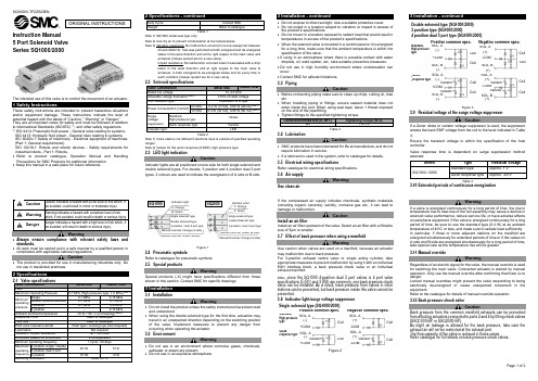
Minimum operating pressure
Single Double (double solenoid) 3 position 4 position
Ambient and fluid temperature
0.1 MPa
0.15 MPa
0.1 MPa
0.1 MPa
0.1 MPa
0.2 MPa
Danger
Danger indicates a hazard with a high level of risk which, if not avoided, will result in death or serious injury.
Warning
• Always ensure compliance with relevant safety laws and standards.
SMC气动阀说明书

3 p o r t d i r e c t a c t i n g v a l v e1063M3PA*M3PB*Note 1: Effective sectional area S and sonic conductance C are converted as S 5.0 C. 10643 p o r t d i r e c t a c t i n g v a l v e1065500 mm 1000 mm 2000 mm 3000 mmSeries variation3PA/3PB SeriesLead wire (11/0.16)1066Electric connection circuit diagram3PA/3PB Series3 p o r t d i r e c t a c t i n g v a l v e1067Pneumatic componentsSafety precautionsAlways read this section before starting use.Refer to Intro 63 for valve general precautions.3 port direct acting valve pneumatic valve 3PA/3PB SeriesThe application differs from the solenoid valve for maintaining the vacuum. When using a pad, set a filter between the pad and valve so that foreign matter does not enter.Do not use this as a solenoid valve for emergency shut down.If left pressurized for a long time, the starting response could be delayed.When using with a vacuum, select direct current (DC) specifications.Install a vacuum filter on the suction port.CAUTIONEnergizing for a long time could impair solenoid valve performance.Similar caution is required in the following use.· During intermittent energizing, it takes longer than non-energizing.· During intermittent energizing, one energizing session exceeds 30 min.Consider heat dissipating measures when installing.Consult with CKD when using this device in a continuous energizing state.During Use & MaintenanceCAUTIONThe surge suppressor enclosed with the solenoid valve is to protect the output contact for that solenoid valve's drive. There is no significant protection for the other peripheral devices, and devices could be damaged or malfunction by the surge. Surge generated by other devices could be absorbed and cause damage such as burning. Care must be taken for points below.(1) The surge suppressor functions to limit a solenoid valve surge voltage, which can reach several hundred V, to a low voltage level that the output contact can withstand. Depending on the output circuit used, this may be insufficient and could result in damage or malfunction. Check whether the surge suppressor can be used by the surge voltage limit of the solenoid valve in use, the output device's withstand pressure and circuit structure, and by the degree of return delay time.If necessary, provide other surge measures. The inverse voltage surge generated when OFF can be suppressed to the following levels.(2) When using the NPN type output unit, the voltage given in the left table and a surge voltage equivalent to the power voltage could be applied on the output transistor. Increase the contact protection circuits in this case.(3) If another device or solenoid valve is connected in parallel to the solenoid valve, the inverse voltage surge generated when the valve is OFF would apply to those devices. Even when using the solenoid valve with surge suppressor for 24 VDC, the surge voltage may reach minus several ten V depending on the model. This inverse polarity voltage could damage or cause the other devices connected in parallel to malfunction. Avoid parallel connection of devices susceptible to reversing polarity voltages, e.g., LED indicators.When driving several solenoid valves in parallel, the surge from other solenoid valves could enter the surge suppressor of one solenoid valve with a surge suppressor. Depending on the current value, that surge suppressor could burn.When driving several solenoid valves with surge suppressors in parallel, surge current could concentrate at the surge suppressor with the lowest limit voltage and cause similar burning. Even if the solenoid valve type is the same, the surge suppressor's limit voltage can be inconsistent, and in the worst case, could result in burning. Avoid driving several solenoid valves in parallel.(4) The surge suppressor incorporated in the solenoid valve often short-circuits if damaged by overvoltage or overcurrent from a source other than the solenoid valve. If the surge suppressor fails, if a large current flows when output is on, the output circuit or solenoid valve could be damaged or ignite. Do not keep power on in a faulty state.Provide an overcurrent protection circuit on the power or drive circuit or use a power supply with overcurrent protection so that alarge current does not flow continuously.(Example of output transistor protective circuit installation 1)(Example of output transistor protective circuit installation 2)Programmable controller sideSolenoid valve sideProgrammable controller sideSolenoid valve side1068D i s c r e t e 3 p o r t d i r e c t a c t i n g v a l v e10693PA/3PB SeriesDiscrete valveHow to order discrete valve10703PA SeriesDiscrete valve: Body portingInternal structure and parts list 2-position single solenoid 3PA1103PA210Repair parts listMain parts list Operational principle3P Series is a pressure balance poppet valve which is not effected by working pressure. This valve maintains large flow rale but low wattage consumption.Port can be pressurized from either 1, 2 or 3 port.The diameters of valve seat and packing seal of stem assembly are same. Since pressure differentials of each port are stabilized by through hole of stem assembly, pressure is well balanced during ON and OFF.When de-energizedThe stem assembly is pushed toward port 1 side by the plunger spring force transmitted by the plunger.Valve seat and packing seal of stem assembly close port 1, while open port 2 and 3.*Port No. 1, 2, 3 indicates; Port 1: P, NC Port 2: A, COM Port 3: R, NO23131*3: Precautions apply when assembling the coil assembly into thevalve. Contact CKD for information.D i s c r e t e 3 p o r t d i r e c t a c t i n g v a l v e10713PB SeriesDiscrete valve: Sub-plate portingInternal structure and parts list2-position single solenoid3PB1103PB210When energizedWhen energizing the coil, the plunger is absorbed toward the coil side, while the stem assembly is moved by the stem spring force. This opens port 1 and 2, but closes port 3.*Port No. 1, 2, 3 indicates; Port 1: P, NC Port 2: A, COM Port 3: R, NO23 1313PA110-M53PA1/3PA2 Series2-position single solenoid: Grommet lead wire Mounting plate: (P) 3PA210-062-position single solenoid: Grommet lead wire Mounting plate: (P)1072D i s c r e t e 3 p o r t d i r e c t a c t i n g v a l v e1073Discrete valve: Body portingDimensionsø4, ø6 push-in joint: (GS4, GS6)3PA1C-connector: (C, C1, C2, C3) D-connector: (D, D1, D2, D3) Locking manual override: (M1)3PA1/3PA2 SeriesTerminal box: (B)Terminal box: (B, L, LS)Terminal box with indicator light: (L, L2, LS)C-connector: (C, C1, C2, C3)D-connector: (D, D1, D2, D3)Locking manual override: (M1)ø4, ø6 push-in joint: (GS6, GS8)3PA2(ø6 push-in joint)10743PB110-063PB1/3PB2 Series2-position single solenoid: Grommet lead wire3PB210-06 082-position single solenoid: Grommet lead wireD i s c r e t e 3 p o r t d i r e c t a c t i n g v a l v e1075Discrete valve: Sub-plate portingDimensionsTerminal box: (B)3PB13PB2C-connector: (C, C1, C2, C3) D-connector: (D, D1, D2, D3)Locking manual override: (M1)C-connector: (C, C1, C2, C3)D-connector: (D, D1, D2, D3)Locking manual override: (M1)3PB1/3PB2 SeriesTerminal box with indicator light: (L, L2, LS)Terminal box: (B, L, LS)Note 2: Response time is the value when ON for supply pressure 0.5 MPa, pre-lubricated. The value varies depending on pressure and quality of lubricant.1076I n d i v i d u a l w i r i n g m a n i f o l d 3 p o r t d i r e c t a c t i n g v a l v e1077M3PA/M3PB SeriesIndividual wiring manifold* Gasket, set screw attachedM3PA/M3PB SeriesIndividual wiring manifoldHow to order individual wiring manifoldHow to order masking plate kit* Gasket and set screw attached5S1MP 2Indicate the quantity.How to order mixed manifold models(1) Indicate the quantity for each function (solenoid position) at the end of the model.Functions and symbols are indicated below.(2) Indicate the function (solenoid position) and layout position in the remarks field.Example: 2-position single solenoid –› S1Example: S1 = 1 to 5 (1 to 5th station is 2-position single solenoid.)2-position single solenoid (S1): 5 piece (1 to 5th station)Masking plate: 2 piece (6, 7th station)M3PB180-06-M1-B-7-3<Example of model number>For 7 stationSolenoid position symbol = , th station (facing the piping port, the left side is the 1st station.)LayoutSymbolS1 = 1 to 5 MP = 6 to 75S1MP2How to order mix manifold5S1MP2S1 = 1 to 5, MP = 6 to 71079M3PA/M3PB SeriesIndividual wiring manifoldI n d i v i d u a l w i r i n g m a n i f o l d 3 p o r t d i r e c t a c t i n g v a l v e1080M3PA180-M5M3PA1/M3PA2 SeriesPort 2 - Individual piping Port 1, 3 - Common porting: Grommet lead wireM3PA280-06Port 2 - Individual piping Port 1, 3 - Common porting: Grommet lead wire3PA119-M5-[Option]-[Voltage]Model no. of discrete solenoid valve for manifold 3PA219-06-[Option]-[Voltage]Individual wiring manifold: Body porting DimensionsM3PA1C-connector: (C, C1, C2, C3) D-connector: (D, D1, D2, D3) Locking manual override: (M1)M3PA1/M3PA2 SeriesTerminal box: (B)Terminal box with indicator light: (L, L2, LS)ø4, ø6 push-in joint: (GS4, GS6)C-connector: (C, C1, C2, C3) D-connector: (D, D1, D2, D3) Locking manual override: (M1)ø6, ø8 push-in joint: (GS6, GS8) Terminal box: (B, L, LS)M3PA2Individualwiringmanifold3portdirectactingvalve10811082M3PB180-06M3PB1 SeriesPort 2 - Individual piping Port 1, 3 - Common porting: Grommet lead wireM3PB180-06APort 2, 3 - Individual piping Port 1 - Common porting: Grommet lead wireModel no. of discrete solenoid valve for manifold 3PB119-00-[Option]-[Voltage]1083Individual wiring manifold: Sub-plate portingDimensionsM3PB1C-connector: (C, C1, C2, C3)D-connector: (D, D1, D2, D3)Locking manual override: (M1)M3PB1 SeriesTerminal box: (B)Terminal box with indicator light: (L, L2, LS)M3PB180-06BPort 1, 2 - Individual piping Port 3 - Common porting: Grommet lead wireø4, ø6 push-in joint: (GS4, GS6)I n d i v i d u a l w i r i n g m a n i f o l d 3 p o r t d i r e c t a c t i n g v a l v e1084M3PB280-06M3PB2 SeriesPort 2 - Individual piping Port 1, 3 - Common porting: Grommet lead wireM3PB280-06YPort 2 - Back porting Port 1, 3 - Common portingM3PB280-06APort 2, 3 - Individual piping Port 1 - Common porting: Grommet lead wireModel no. of discrete solenoid valve for manifold 3PB219-00-[Option]-[Voltage]Model no. of discrete solenoid valve for manifold 3PB219-00-[Option]-[Voltage]JIS symbolJIS symbol1085Individual wiring manifold: Sub-plate portingDimensionsM3PB2C-connector: (C, C1, C2, C3)D-connector: (D, D1, D2, D3)Locking manual override: (M1)M3PB2 SeriesTerminal box: (B, L, LS)M3PB280-06BPort 1, 2 - Individual piping Port 3 - Common porting: Grommet lead wireø6, ø8 push-in joint: (GS6, GS8)I n d i v i d u a l w i r i n g m a n i f o l d 3 p o r t d i r e c t a c t i n g v a l v e10862°3PA/3PB SeriesTechnical data (1) How to wire terminal box wiring and connectorHow to wire terminal box wiring and connectorRefer to the following drawing, and wire the terminal boxfollowing steps 1) to 3) below.1) Pass the cap (4), washer (5), and gasket (6) in order through the cabtire cable (7), and insert in case (2).2) When using a crimp terminal, treat the cabtire cable (7) at an appropriate length as shown in the figure, and crimp the crimp terminal (8) onto the end.3) Remove screw (10) from terminal gland (3), and pass through crimp terminal (8). (When using the Y type terminal, loosen and sandwich the terminal.) Then, tighten screw (10) again. Note: Tighten at torque of 0.5 N·m ±15%.Remarks: Bare wires can be wired. In this case, loosen screw (10), andinsert leads into the fitting, then tighten again.The cord’s direction can be changed by pulling the gland out of the case, rotating it 180°, then pressing it into the case again.The following crimp terminals (8) can be used.Use equivalent products when using other brands.3 p o r t d i r e c t a c t i n g v a l v e1087O.D. ø4 to 6.5Tighten the lead wire with the set screw.A small flat-tipped screwdriver is required.23( )Note: Do not tighten together with thesurge suppressor.Insert the gasket andterminal block into the voltage terminal and grounding terminal.Technical data (1) How to wire terminal box wiring and connector3PA/3PB SeriesPower consumption 1.8 W becomes 2.0 W when the 24 VDC light is enclosed.。
SMC电子比例阀说明书
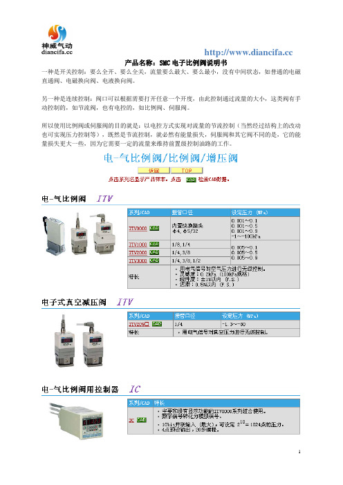
产品名称:SMC电子比例阀说明书
一种是开关控制:要么全开、要么全关,流量要么最大、要么最小,没有中间状态,如普通的电磁直通阀、电磁换向阀、电液换向阀。
另一种是连续控制:阀口可以根据需要打开任意一个开度,由此控制通过流量的大小,这类阀有手动控制的,如节流阀,也有电控的,如比例阀、伺服阀。
所以使用比例阀或伺服阀的目的就是:以电控方式实现对流量的节流控制(当然经过结构上的改动也可实现压力控制等),既然是节流控制,就必然有能量损失,伺服阀和其它阀不同的是,它的能量损失更大一些,因为它需要一定的流量来维持前置级控制油路的工作。
SMC电磁阀SY9140-4DZD说明书
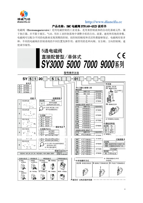
电磁阀用电磁控制的工业设备,是用来控制流体的自动化基础元件,属于执行器,并不限于液压、气动。用在工业控制系统中调整介质的方向、流量、速度和其他的参数。电磁阀可以配合不同的电路来实现预期的控制,而控制的精度和灵活性都能够保证。电磁阀有很多种,不同的电磁阀在控制系统的不同位置发挥作用,最常用的是单向阀、安全阀、方向控制阀、速度调节阀等。
