AUTODESK revit mep 2010教程3
Autodesk Revit Architecture 2010 认证准备指南说明书

Autodesk ® Certification Exam Guide Autodesk ®Revit ®ArchitecturePreparation Guide for Autodesk Revit Architecture 2010 Certified Associate and Autodesk Revit Architecture 2010 Certified Professional Certification Exams.This guide is intended as a resource in your preparation for the exams to become Autodesk certified. It will help you understand the structure and content of the exam, and to develop a personal strategy to successfully pass the Autodesk Revit Architecture 2010 Certified Associate and Certified Professional exams, and includes information on re-certifi c ation from Autodesk Revit Architecture 2009 Certified User.About Autodesk Professional Certification Autodesk certifications are industry-recognized credentials that can help you succeed in your design career – providing benefits to both you and your employer. Autodesk certifications are a reliable validation of skills and knowledge, and can lead to accelerated professional development, improved productivity, and enhanced credibility.Getting CertifiedTo earn Autodesk Certification, you must pass the required Autodesk Certification exams. Step through each of these areas to help ensure your success:• C hoose the Certification that’s right for you: Choose the level and the Autodesk application that best applies to you. Understand the requirements for the Certification you want to earn.• A ssess your readiness and take a practice test: Take an assessment test to assess your knowledge of the product. And then take a practice test for the Professional-level exam to gain experience using the testing system.• G et the training you need: Autodesk Official Training Guides, or take classes at an Autodesk Authorized Training Center (ATC ®).• A pply your training and practice your skills: Practice what you’ve learned to gain experience.• T ake the required exam: Register for your exam at an Autodesk Authorized Certification Center.Autodesk certification exams are delivered at Autodesk Authorized Certification Centers. All exams are computer-delivered in a proctored environment. You can find the locations of Autodesk Certification Centers near you using the Center Search function on Authorized Certification CenterAutodesk Revit Architecture 2010Certified Associate Exam Summary Information The Autodesk Revit Architecture 2010 Certified Associate exam is an on-line examination consisting of 30 questions that assess your know l edge of the tools, features, and common tasks in Autodesk Revit Architecture 2010.Question types include multiple choice, matching, and point and click (hotspot).The exam has a one hour time limit (in some countries the time limit may be extended). At the conclusion of the exam, you will receive a comprehensive score report which includes summary information on the questions you missed and where you can find information on that area in the corresponding Autodesk Official Training Guide.Autodesk Revit Architecture 2010 Certified Professional Exam Summary InformationThe Autodesk Revit Architecture 2010 Professional Certification exam is a performance based test. Performance based testing is defined as testing by doing. That means that rather than answer questions about how you might accomplish a task, you actually perform the task.The Autodesk Revit Architecture 2010 Certified Professional exam is comprised of 20 questions. Each question requires you to use the Autodesk application to create or modify a data file, and then to type your answer into an input box on the screen. The answer you enter will either be a text entry or a numeric value. The exam has a 90 minute time limit (in some countries the time limit may be extended).To earn the credential of Autodesk Revit Architecture Certified Professional, you must also pass the Autodesk Revit Architecture Certified Associate exam. You can pass the exams in any order.Autodesk ®Certification Exam Summary InformationExample of Certified Professional Test Item Open the drawing file Copy-Dining-Chair.dwg. 1. U sing the insertion point of Dining Chairs “A and “B”, copy the Dining Chairs, 712.8 units along the edge of the Dining Table as shown. Using the Distance command, what is the distance (to the nearest integer) from the corner of Dining Chair labeled “D” to the corner of Dining Chair labeled “E” as shown?The answer is: 1081Exam Preparation – Your Key to Success Autodesk highly recommends using a variety of resources to prepare for certification exams. In all cases, you should start with the exam objectives to determine which tasks will be covered on the exams. Equally as important, actual hands-on experience is required. From there, we recommend that you choose the preparation option that best fits your needs. Details on Autodesk recommended preparation solutions are available in this guide. During preparation, it is important that you review the exam objectives periodically to make sure that all of the material in the exam is covered in your choice of preparation methods. Please note that some material on the test maynot be covered in your choice of preparation materials. This is why it is critical that you refer to the list of exam objectives during your course of study. Recommended Experience Levels for AutodeskRevit Architecture 2010 Certification ExamsActual hands-on experience is a criticalcomponent in preparing for the exam. Directapplication of the skills learned cannot besubstituted by any one other learningresource. You must spend time using theproduct and applying the skills you havelearned.Because experience using the Autodeskapplication is so important, we recommenda minimum level of experience beforeattempting the exam. Note that even withthe recommended level of experience, youshould still use the exam objectives as abasis for your preparation. Even the mostknowledgeable and experienced users ofAutodesk applications will need to focus theirstudy specifically on the exam objectives.Exam ObjectivesReview the exam objectives to see the completelisting of topics for the exam. Use this as yourchecklist to determine your weaknessesand areas on which you will want to focus moreattention in your study and preparation.Recommended Experience Levels2010 Certified Associate exam – LearningAutodesk Revit Architecture 2010 course(or equivalent) plus 100 hours of hands-onapplication2010 Certified Professional exam – LearningAutodesk Revit Architecture 2010 course(or equivalent) plus 400 hours of hands-onapplicationAutodesk Assessment TestsAutodesk assessment tests will help determine your general knowledge of the Autodesk application on which you are seeking certification. This will identify areas of knowledge that you should develop in order to prepare for the certification exam. At the completion of an Autodesk Assessment test you will receive a comprehensive score report and also be able to review the items you missed and their correct answers. Assessment tests can be purchasedat .Autodesk Official Training GuidesAutodesk publishes dozens of Training Guides every year designed to help users at all levelsof expertise improve their productivity with Autodesk software. Training Guides from Autodesk are the preferred classroom training material for Autodesk Training Centers. These same Training Guides are well-suited for self-paced learning.Students simulate real-world projects and work through hands-on, job-related exercises. Most titles include a trial version of the software.The objectives in the Autodesk Certified Associate and Professional exams come directly from Autodesk Official Training Guides. If you will be taking a professional level exam the test questions will use the drawings that are made available to you with the corresponding Autodesk Official Training Guides.The recommend Autodesk Official TrainingGuides for the Associate and Professional examis Learning Autodesk Revit Architecture 2010.You can purchase the courseware at or contact your local ATC.Academic Centers in North America canpurchase guides from an Autodesk AcademicValue Added Reseller at /educationand select “locate a reseller”.ATC® Instructor-Led CoursesEvery day, thousands of customers are taughthow to realize their ideas, faster, with Autodesksoftware. You can perform smarter and betterwith Autodesk software products when youturn to an Authorized Training Center. An ATCis your best source for Autodesk-authorizedclasses, tailored to meet the needs and challengesfacing today’s design professionals, and to helpyou prepare for your Autodesk Certificationexams.The Autodesk Authorized Training Center (ATC®)program is a global network of professionaltraining providers offering a broad range oflearning resources. In many areas, you can earncontinuing education credits while buildingyour toolset. Visit the online ATC locator at/atc.Autodesk Revit Architecture 2010Professional Level Practice TestsIn order to allow you to gain experience with theProfessional level test and the testing system,Autodesk has developed a practice test thatsimulates the actual 2010 Certified Professionalcertification exam. It is a performance basedexam, with the same number of questions asthe actual exam. It requires the use of the specificAutodesk application in order to successfullyanswer the questions. This test can be taken inan Autodesk Certification Center or fromyour own computer. For more information onpurchasing Autodesk Professional Practicetests see .Test Taking StrategiesEach time you take a test, whether it is anassessment test, practice test, or thecertification exam, you will benefit from usingproven test taking strategies to increase yourodds of success. Some of these strategiesare general, but some are very specific to thetype of exam you may be taking.Time ManagementBecause Autodesk certification exams are timed,management of time during testing is anintegral part of a successful outcome. Autodeskrecommends that you use a strategy thatmaximizes the time available so that you willhave time to answer each exam question. TheAutodesk Online test system allows you to markquestions for review and return to them later.This allows you to work through the testquestions that are easy or quick for you, andmark the more difficult questions to return tolater if time permits. It is important to not allowyourself to become caught up in one specificexam question and waste time. Also, be sure tocheck the review screen before you submit yourexam, to make sure you have answered all ofthe items.Thoroughly Read ExamQuestions and InstructionsAutodesk exams are testing specific objectivesso it is critical that you understand the questionsbefore you answer them. Additionally, beforeeach test you are presented with a tutorial.This tutorial contains information on usingthe Autodesk Online testing system as wellas critical information such as location of files,instructions for answering questions, andgeneral test information.Example Training Guides from AutodeskExam Registration, Purchase, and Scheduling When you are ready to take your exam, you may purchase your exam directly from the Autodesk Online Testing Service or from an Autodesk Authorized Certification Center depending on the country in which you will test. Information on purchasing and scheduling your exam can be found at .During Your ExamWhile taking the exam, you may not use calculators, books, or other electronic equip-ment. You may use scratch paper, but it will be collected from you when you finish your test. You may pause the test during delivery, andno time will be lost. The proctor will seat you and step you through the process of starting your test. They will also answer any questions you have about the testing process. They will not answer any questions about test questions or the content of the test. After Your ExamAfter your certification exam you will immediately receive an online score report that contains diagnostic feedback. This feedback includes the number of items that are correct in each section. This score report contains the objectives for any items that were incorrect. This score report in available in your Autodesk Online profile, and can be reviewed and printed at anytime from .If you passed the required exams to earn certification, you will also have access to electronic certificate: suitable for printing and framing. You will also have access to official Autodesk certification logos which you can use on your business cards, resume, and letterhead. The certificate and logos are available in your certification profile.Once certified, you can also choose to have your contact information and certifications listed in Autodesk’s publicly available database. This is an excellent way to demonstrate your certification status to prospective employers. The database listing can be found on . In order to display your certification log into your Autodesk Online profile and select “yes” to the field “I would like my certification status published to the Autodesk website”. You may change this field at anytime to remove or display your certifications.Autodesk® Certification Exam GuideExam Registration, Purchase, and SchedulingAutodesk Inventor 2010This number certifies thatthe recipient has successfullycompleted all programrequirements.In recognition of their commitment to achieving professional excellence, this certifies thathas successfully completed the program requirements ofDate Carl BassPresident, Chief Executive OfficerLeveraging the Autodesk brand can help youin your career. Autodesk Certification providesyou with an Autodesk logo that you candisplay on your resume and business card, anda beautiful e-certificate suitable for framing.This customized certificate gives instantrecognition that your credential is issuedby Autodesk.Revit Architecture 2010This number certifies thatthe recipient has successfullycompleted all programrequirements.In recognition of their commitment to achieving professional excellence, this certifies thathas successfully completed the program requirements ofDate Carl BassPresident, Chief Executive OfficerAutoCAD2010This number certifies thatthe recipient has successfullycompleted all programrequirements.In recognition of their commitment to achieving professional excellence, this certifies thathas successfully completed the program requirements ofDate Carl BassPresident, Chief Executive OfficerThe Autodesk Official Training Guide for this exam is Learning Autodesk Revit Architecture 2010. You can purchase this guide at or from your local ATC. Schools can also purchase from an Autodesk Academic Value Added Reseller at /education and select “locate a reseller”.Revit Architecture Basics 2- Describe the different types of building elements.Chapter 2: Revit Architecture Basics - Describe project templates.Starting a Design2- Create a floor plan view and place building elements in it.Chapter3: Starting a Design- Describe levels and their uses.The Basics of the Building Model 2- Describe wall properties.Chapter4: The Basics of the Building Model - Describe compound walls.Loading Additional Building Components 1- Add components.Chapter5: Loading Additional BuildingComponentsViewing the Building Model 4- Describe view properties.- Describe object visibility settings.- Create and modify section and elevation views.- Describe 3D view types.Using Dimensions 2- Describe permanent dimensions.Chapter7: Using Dimensions andand Constraints- Describe constraints and the types of constraints.ConstraintsDeveloping the 5- Describe floors.Chapter8: Developing the Building Model Building Model- Add and modify ceilings in a building model.- Describe roofs.- Create curtain walls and modify curtain grids.- Create stairs and railings.Detailing and Drafting5- Describe callouts.Chapter9: Detailing and Drafting- Describe text.- Describe tags.- Create detail views.- Describe drafting views.Construction Documentation 3- Describe the properties of schedules.Chapter10: Construction Documentation - Describe rooms.- Describe legends.Presenting the Building Model 4- Describe drawing sheets.Chapter 11: Presenting the Building Model - Describe titleblocks.- Create revision clouds.- Describe renderings.The Autodesk Official Training Guide for this exam is Learning You can purchase this guide at or from your local ATC. Schools can also purchase from an Autodesk Academic Value Added Reseller at /education and select “locate a reseller”.Starting a Design 1- Create and modify levels.Chapter 3: Starting a DesignThe Basics of the Building Model3- Create compound and vertically compound walls.Chapter 4: The Basics of the Building Model- Add and modify walls using editing commands.- Add doors to a building model.Loading Additional Building Components 1- Load component families and add components in a project.Chapter 5: Loading Additional Building ComponentsViewing the Building Model 2- Control object visibility.Chapter 6: Viewing the Building Model - Create and modify section and elevation views.Using Dimensions and Constraints 2- Work with dimensions in a building model.Chapter 7: Using Dimensions and Constraints- Apply constraints to elements in a building model.Developing the Building Model4- Create and modify floors.Chapter 8: Developing the Building Model- Add and modify ceilings and ceiling components.- Add and modify roofs.- Create and modify stairs and railings.Detailing and Drafting 3- Create a callout view of a section.Chapter 9: Detailing and Drafting- Work with text and tags.- Add construction details to a detail view.Construction Documentation 2- Create a component and a key schedule.Chapter 10: Construction Documentation- Create a room and room schedule.Presenting the Building Model2- Create, modify, and specify print options for drawing sheets.Chapter 11: Presenting the Building Model- Add and update titleblocks and edit titleblock families.Autodesk and Autodesk Revit are registered trademarks or trademarks of Autodesk, Inc., in the USA and/or other countries. All other brand names, product For further information: /certificationemail:**************************。
Revit MEP 管件族3:查找表格功能

以上图片在管件的样本中很常见,可以发掘管件族的一个特殊之处:尺寸参数都是随公称直径的变化而变化的。
换而言之当公称直径改变时,其他的尺寸需要随着一起变化,才能保证管件的形状符合要求。
Revit MEP自身独特的查找表格功能可以满足管件族的这一特别要求。
查找表格就是将管件族模型需要的数值输入到配套的.csv文件中,在.rfa文件中根据公称直径查找.csv中的数据,获得相应尺寸值。
下面详述该功能是如何工作的:1. csv 格式详析∙占位列不能为空;∙表头格式要求如下:以ND##length##millimeters为例,ND为Nominal Diameter的缩写,Length为ND属性,即ND为一长度参数,millimeters说明该列参数的单位,在表头里以复数形式出现。
2.csv数据读取在RME中可以通过特定的公式来读取.csv文件中的数据。
格式如下:text_file_lookup(查找表格名 , 查找值 , 查找失败默认值 , 查找依据1 ,…. , 查找依据n)查找表格名为管件族内嵌参数,其值即为该管件族需要调用的csv文件名称。
通常一个管件族对应一个csv文件,方便管理。
举例: M_弯头 - PVC – Sch 40.rfa中心到端点= text_file_lookup(查找表格名, “CtE”, 找不到中心到端点,公称直径,角度1)这里有两个查找依据:公称直径和角度1。
在族类型中可以查出公称直径为15mm,角度1为90度。
查找依据应为族类型中所设参数。
查找值为“CtE”,根据公式得到的值就为 1.25 x 25.4 =31.75 mm 与族类型中31.8mm 相符合。
注: 1 inch = 25.4 mm如果族类型中公称直径的输入值为18mm,此时在.csv中无法找到对应的数值,那么“中心到端点”这个参数的取值将与“找不到中心到端点”参数一致。
3.查找表格文件即.csv文件的路径默认安装的情况下,查找表格文件即.csv文件都放在C:\Documents and Settings\All Users\Application Data\Autodesk\RME 2010\LookupTables。
Autodesk Revit 土建应用项目教程第三章
• (1)选择任意一根轴网线,单击标头外侧方框,即可关闭/ 打开轴号 显示。
• (2)如需控制所有轴号的显示,可选择所有轴线自动激活“修改│ 轴网”选项卡。在“属性”面板中选择“编辑类型”命令,弹出“类 型属性”对话框,在其中修改类型属性参数,单击端点默认编号的 “√”标记,如图3-17 所示。
• 3.2.4 尺寸驱动调整轴线位置
• 选择任何一根轴网线,会出现蓝色的临时尺寸标注,单击尺寸即可修 改其值,调整轴线位置,如图3-15 所示。
上一页 下一页 返回
3.2 项目轴网创建
• 3.2.5 轴网标头位置调整
• 选择任何一根轴网线, 所有对齐轴线的端点位置会出现一条对齐虚 线,用鼠标拖曳轴线端点,所有轴线端点都将同步移动。
F3),在F2 与F3 之间会显示一条蓝色临时尺寸标注,单击临时尺寸 标注上的数字,重新输入新的数值并按回车键,即可完成标高高度的 调整,如图3-4 所示(标高高度距离的单位为mm)。
上一页 下一页 返回
3.1 项目标高创建
• 3.1.2 复制、阵列标高
• 选择二层标高F2,选择“修改│标高”选项卡,然后在“修改”面板 中选择“复制” 或“阵列”命令,可以快速生成所需标高。
3.2 项目轴网创建
• 3.2.7 轴号偏移
• 单击标头附近的“添加弯头” 符号,单击“拖曳点”并按住鼠标不 放, 调整轴号位置, 如图3-20 所示。
• 偏移后若要恢复直线状态,单击后拖动“拖曳点”到直线上释放鼠标 即可。
• 【注意】轴网锁定状态下要取消偏移,需要选择轴线并取消锁定后, 才能移动“拖曳点”。
• (1)如果只需移动单根轴线的端点, 则先打开对齐锁定,再拖曳轴 线端点。
Autodesk Revit Structure 2010软件介绍说明书
Building Information Modeling for Structural Engineering BIM for structural engineers follows this same methodology for the entire structural engineering process, focusing on a digital model that can be used for coordination with architects; mechanical, electrical, and plumbing engineers; and civilengineers that is integrated with analysis, design, and construction documentation, and extending that digital model from design through fabrication and construction.Autodesk Revit StructureAutodesk Revit Structure software integrates multimaterial physical and analytical models,providing concurrent structural modeling for more effi cient, more up-to-date documentation, as well as tighter integration for analysis and design.The foundation of BIM for structural engineering.Autodesk ®Revit®Structure 2010Autodesk Robot Structural Analysis ProfessionalAutodesk Robot Structural Analysis Professional software is a collaborative, versatile, and fast structural analysis and design application that incorporates BIM, allowing engineers to readily analyze a wide variety of structures.AutoCAD Structural DetailingAutoCAD ® Structural Detailing software is a powerful solution for faster and effi cient detailing and creation of fabrication shop drawings for reinforced concrete and steel structures.Building information modeling (BIM) is anintegrated process built on coordinated, reliable information about a project from design through construction and into operations. By adopting BIM, architects, engineers, contractors, andowners can more easily create coordinated, digital design information and documentation; use that information to visualize, simulate, and analyze performance, appearance, and cost; and reliably deliver the project faster, more economically, and with reduced environmental impact.Integrated tools for modeling, coordination, analysis, design documentation, as well as shop drawings and fabrication.Improve Efficiency, Accuracy, and Coordination Autodesk Revit Structure software improves the way structural engineers and drafters work. It minimizes repetitive modeling and drawing tasks, as well as errors due to manual coordination between structural engineers, architects, and drafters. It helps reduce time spent producing fi nal construction drawings and increases the accuracy of documentation, improving overall project deliverables for clients.Seamless CoordinationBecause Autodesk Revit Structure uses building information modeling (BIM), every view, drawing sheet, and schedule represents the sameunderlying database. As project team members work on the same project, making inevitable and necessary changes to the building structure, parametric change technology in Autodesk Revit Structure automatically coordinates changes across all other representations of the project—model views, drawing sheets, schedules, sections, plans, and details. The design and documentation stay coordinated, consistent, and complete.Bidirectional AssociativityThe building model and all of its views are part of the same information system. This means changes to any part of the structure need to be made only once, maintaining consistency throughout the documentation set. For example, if the sheet scale changes, the software automatically resizes annotations and graphics. If a structural member changes, any views that include the element are coordinated and updated automatically, including name tags and other labels referring to the element properties.Autodesk ® Revit Structure software off ers concurrent modeling for structural design, analysis, and coordinateddocumentation.Whether engineers are designing steel, cast-in-place concrete, precast concrete, masonry, or wood structures, standard modeling objects in Autodesk Revit Structure software include walls, beam systems, columns, slabs, and foundations. Additional structural objects can be created as parametric components.Parametric ComponentsUsing Autodesk Revit Structure, engineers can create many types of structural components, such as joist systems, beams, open web joists, trusses, and intelligent wall families. No programming language is required to use parametriccomponents, also known as families. The family editor contains all the data to graphically represent an element in 2D and 3D at various levels of detail.Multiuser CollaborationAutodesk Revit Structure enables multiple team members on the same network to work together on a model, while their work stays fully coordinated. A complete range of collaboration modes provides fl exibility to meet the project team’s workfl ow—from on-the-fl y, simultaneous access to the shared model to formal division of the project into discrete shared units or individually managed linked models.Design OptionsWith Autodesk Revit Structure, engineers stay focused on structural engineering. Explore design changes. Develop and study several designalternatives to make key design decisions. Easily present multiple schematic designs to clients. Each option can be substituted into the model for visualization and quantity takeoff to help team members and clients make informed decisions.Integrate with Leading Analysis and Design Physical models drive constructiondocumentation. Drafters use physical models to produce the drawing and detail sheets. Engineers and architects use it for coordination purposes, such as interference checking.The analytical model contains information such as loads, load combinations, member sizes, and release conditions for use in leading third-party analysis applications. The analytical model could be the entire building model, one wing of the building, or even a single structural frame. Engineers use selection fi lters with structural boundary conditions to send substructures (such as a frame, fl oor, or wing of the building) to their analysis software without sending the entire model.The creation of the analytical model uses engineering rules to produce a consistentanalytical representation of the physical structure. Engineers can override initial analytical settings and edit the analytical model before linking to structural analysis packages.Enhance Structural Modeling and Analysis Capabilities Autodesk Revit Structure inspires structural engineers to greater engineering insight: user-defi ned rules help the analytical models adjust their location to the analytical projection planes of attached or adjacent structural elements. Engineers can automatically check analytical inconsistencies such as missing supports, global instabilities, or framing anomalies before sending the model to structural analysis. The analysis programs then return the design information and dynamically update the physical model and documentation, eliminating many redundant, repetitive tasks such as modeling frames and shells in a variety of diff erent applications. Autodesk Revit Structure integrates with Autodesk ® Robot™ Structural AnalysisProfessional software as well as other widely-used analysis and design applications. To fi nd out which software partners have linked their applications to Autodesk Revit Structure through the Revit ® platform API (application programming interface),visit /autodeskrevitstructure.Autodesk Revit Structure focuses on the modeling of multimaterial building structures and bidirectionallylinks with widely-used analysis and design programs.Deliver Comprehensive Construction Documents Material-specifi c tools help ensure that construction documents conform to industry and offi ce standards. For steel, features such as beam coping andautomatic symbolic cutbacks, as well as an extensive library of detail components, are available. For concrete structures, display options provide control over the visibility of the concrete elements. Reinforcement bars are also available for concrete elements such as columns, beams, walls, and foundations.Automatic Sections and ElevationsCreating sections and elevations in Autodesk Revit Structure is simple compared to traditional methods. Because views are just a diff erentrepresentation of the entire building model, users get instant cuts throughout a structure. Use them at any time to work in the most appropriate view. When the construction documents are ready to print, section tags and elevation symbols of the views that are not placed onto any drawing sheet are automatically hidden.Automatic Drawing Sheet ReferencesThis functionality helps ensure that no section, elevation, or callout references the wrong drawing or sheet and that all data and graphics, details, schedules, drawings, and sheets in the drawing set are current and coordinated.DetailsAutodesk Revit Structure allows callouts for typical details and for specifi c ones. Entire sheets of typical details can be created from scratch in Autodesk Revit Structure using its traditional 2D drafting tools.Designers can also import DWG™ details from AutoCAD ® software and linked into Autodesk Revit Structure, using the project browser to manage them.Specifi c details come directly from the views of the model. These model-based details are completed with 2D parametric components (metal deck, concrete masonry unit, anchor bolts in footings, fasteners, welded symbols, steel connectionplates, concrete rebar, and more) and annotations such as text and dimensions.When the geometry gets complicated, Autodesk Revit Structure off ers 3D model-based details such as 3D representation of building expansion joints, steel connections, rebar in concrete elements, and more.SchedulesSave time by creating schedules on demand, and update the model and views automatically simply by making a change in a schedule. Schedule features include sorting, fi ltering, grouping, and counting, as well as user-defi ned formulas.Engineers and project managers can use customized schedules to check the overallstructural design. For example, they can schedule and review structural loads before integrating the model with analysis software. If the load value needs to be changed, it can be modifi ed in the schedule and automatically coordinatedthroughout the model.Autodesk Revit Structure has a comprehensive set of dedicated tools to deliver structural drawings and reduceerrors due to manual coordination of design changes.Collaboration with ArchitectsAutodesk Revit Structure software also supports the workfl ow where structural modeling starts with an architectural design done in AutoCAD ® Architecture software. Engineers can reference individual plan views from AutoCAD Architecture when they start their structural layout. For better coordination, structural engineers can export 3D Autodesk Revit Structure models to AutoCAD Architecture. Architects using AutoCAD Architecture 2009 can review the exported structural elements as true AutoCAD Architecture objects.Engineers working with architects using Autodesk ® Revit ® Architecture software can experience the advantages of BIM and share the same underlying building database. Creation of the structural model is faster with integrated Autodesk Revit platform tools. With interference checking between structural and architectural objects, engineers can quickly detect coordination problems before sending drawings to the construction site.Collaboration with Mechanical, Electrical, and Plumbing EngineersStructural engineers working with mechanical, electrical, or plumbing engineers using AutoCAD ® MEP software can improve design coordination. Autodesk Revit Structure users can export their structural model into AutoCAD MEP, where the MEP engineer can perform clash detection between pipes and structural elements. Autodesk Revit Structure can also import 3D duct and pipe objects from AutoCAD MEP into the structural model via ACIS ® solids to detect interferences visually. In addition, structural engineers who are working with MEP engineers using Autodesk ® Revit ® MEP software can take full advantage of building information modeling.。
Autodesk Inventor 2010 培训教程 第3章(文字版)
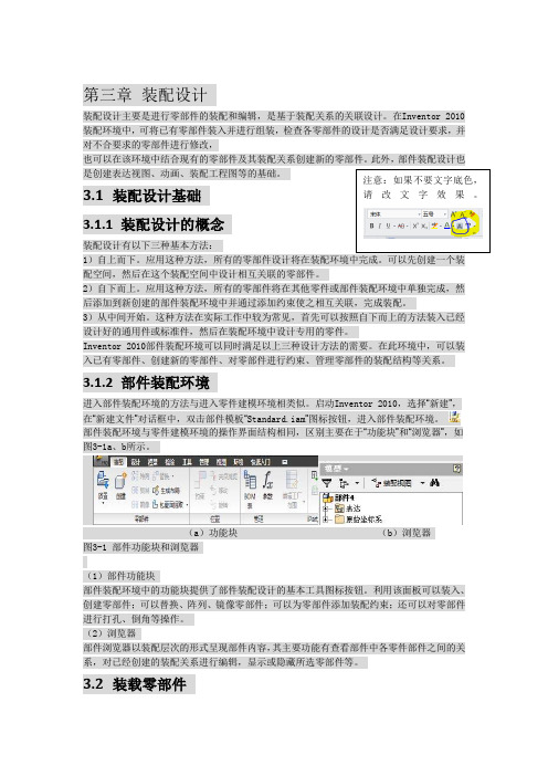
第三章 装配设计装配设计主要是进行零部件的装配和编辑,是基于装配关系的关联设计。
在Inventor 2010装配环境中,可将已有零部件装入并进行组装,检查各零部件的设计是否满足设计要求,并对不合要求的零部件进行修改,也可以在该环境中结合现有的零部件及其装配关系创建新的零部件。
此外,部件装配设计也是创建表达视图、动画、装配工程图等的基础。
3.1 装配设计基础3.1.1 装配设计的概念装配设计有以下三种基本方法:1)自上而下。
应用这种方法,所有的零部件设计将在装配环境中完成。
可以先创建一个装配空间,然后在这个装配空间中设计相互关联的零部件。
2)自下而上。
应用这种方法,所有的零部件将在其他零件或部件装配环境中单独完成,然后添加到新创建的部件装配环境中并通过添加约束使之相互关联,完成装配。
3)从中间开始。
这种方法在实际工作中较为常见,首先可以按照自下而上的方法装入已经设计好的通用件或标准件,然后在装配环境中设计专用的零件。
Inventor 2010部件装配环境可以同时满足以上三种设计方法的需要。
在此环境中,可以装入已有零部件、创建新的零部件、对零部件进行约束、管理零部件的装配结构等关系。
3.1.2 部件装配环境进入部件装配环境的方法与进入零件建模环境相类似。
启动Inventor 2010,选择“新建”,在“新建文件”对话框中,双击部件模板“Standard.iam ”图标按钮,进入部件装配环境。
部件装配环境与零件建模环境的操作界面结构相同,区别主要在于“功能块”和“浏览器”,如图3-1a 、b 所示。
(a )功能块 (b )浏览器 图3-1 部件功能块和浏览器(1)部件功能块部件装配环境中的功能块提供了部件装配设计的基本工具图标按钮。
利用该面板可以装入、创建零部件;可以替换、阵列、镜像零部件;可以为零部件添加装配约束;还可以对零部件进行打孔、倒角等操作。
(2)浏览器部件浏览器以装配层次的形式呈现部件内容,其主要功能有查看部件中各零件部件之间的关系,对已经创建的装配关系进行编辑,显示或隐藏所选零部件等。
AutoCAD建筑制图教程2010第3章

2017年7月4日
9
§3.3.3
倒角
倒角使用一条斜线连接两个对象,倒角时既可以输入 每条边的倒角距离,也可以指定某条边上倒角的长度及与 此边的夹角。使用CHAMFER命令时,还可以设定是否 修剪被倒角的两个对象 。
命令启动方法如下。 功能区:单击【常用】选项卡【修改】面板上的 按钮, 如果没有,则单击【常用】选项卡【修改】面板上的 按 钮右边 按钮,在打开下拉列表中单击 按钮。 命令:CHAMFER 或简写 CHA。
命令启动方法如下。 功能区:单击【常用】选项卡【修改】面板上的 按钮。 命令: MIRROR 或简写 MI。
2017年7月4日
5
§3.2 旋转、阵列对象
§3.2.2 旋转对象
使用ROTATE命令可以旋转图形对象,改变图形对 象的方向。使用此命令时,只需指定旋转基点并输入旋转 角度就可以转动图形实体。此外,也可以将某个方位作为 参照位置,然后选择一个新对象或输入一个新角度值来指 明要旋转到的位置 。
命令启动方法如下。 功能区:单击【常用】选项卡【修改】面板上的 按钮。 命令: ARRAY 或简写 AR。
2017年7月4日
7
环形阵列对象
使用ARRAY命令既可以创建矩形阵列,也可以创建 环形阵列。环形阵列是指把对象绕阵列中心等角度均匀分 布,决定环形阵列的主要参数有阵列中心、阵列总角度及 阵列数目。此外,也可通过输入阵列总数及每个对象间的 夹角生成环形阵列 。
2017年7月4日
11
§3.5 拉伸对象
STRETCH命令可拉伸、缩短、移动实体。该命令通 过改变端点的位置来修改图形对象,编辑过程中除被伸长、 缩短的对象外,其他图元的大小及相互间的几何关系将保 持不变 。
REVIT MEP软件教程 3-3 卫浴系统(70页)
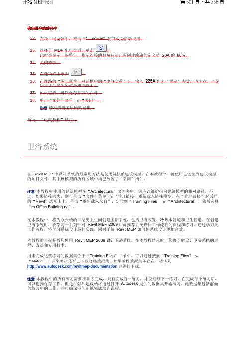
确定进户线的尺寸32.在项目浏览器中,双击“1 - Power "使其成为活动视图。
33.选择了 MDP 配电盘后,单击 。
此时会显示一条警告,指示连接的总负荷超出所创建线路的定义值 20A 的 80%。
34.关闭警告。
35.在选项栏上单击。
36.在线路的“图元属性”对话框中的“电气负荷”下,输入 225A 作为“额定”参数。
请注意,“导线尺寸”参数的值会相应修改。
37.如果需要,可以保存打开的文件。
38.单击“文件”菜单“关闭”。
注意请不要覆盖原始数据集。
至此,“电气教程”结束。
在 Revit MEP 中设计系统的最常用方法是使用链接的建筑模型。
在本教程中,将使用已链接到建筑模型的项目文件,其中该模型的所有区域中均已放置了“空间”构件。
注意本教程中使用的建筑模型在“Architectural "文件夹中。
您应该维护指向建筑模型的相对路径。
不过,如果链接丢失,则可单击“文件”菜单 “管理链接”重新载入链接模型。
在“管理链接”对话框的“Revit "选项卡上,单击“重新载入来自”,定位到“Training Files "“Architectural ",然后选择“m Office Building.rvt "。
在本教程中,将为办公楼的二层男卫生间创建卫浴系统,包括卫浴装置、冷热水管道和卫生管道。
在创建卫浴系统时,要学习一系列针对 Revit MEP 2009 讲解推荐系统设计工作流程的课程和练习。
通过学习此工作流程,将学习系统设计最佳实践,同时了解 Revit MEP 如何使系统设计更加高效。
本教程的目标是教您使用 Revit MEP 2009 设计卫浴系统。
在本教程结束时,您将了解设计卫浴系统的过程、方法和专用技术。
用来完成这些练习的数据集位于“Training Files "目录中。
可以通过搜索“Training Files "“Metric "目录来确认是否已下载这些数据集。
如果教程数据集不存在,请转到 /revitmep-documentation 并进行下载。
Autodesk Revit 基础操作

04 2.4 基本绘图工具及应用
2.4.4绘制圆
可通过指定圆形的中心点和半径来绘制圆形。
2.4.2绘制矩形
绘制曲线或圆角时可使用多个圆弧工具
起点-终点-半径弧、中心-端点弧、起点-终点-半径弧
2.4.6绘制椭圆
通过在 2 个方向上选择中心点和半径,可以绘制椭圆。
2.4.7绘制样条曲线
具体方法:绘制一条经过或靠近指定点的平滑曲线。
03 2.3 运用标高和轴网、工作平面
2.3.4工作平面
➢ 根据名称指定新的工作平面:用于列表中 包括标高、网格和已命名的参照平面。
➢ 拾取一个工作平面:可以拾取模型中的一 个面作为参照平面。
2.4 基本绘图工具及应用
04 2.4 基本绘图工具及应用
将形体放置于三面投影体系中,并注意安 放位置适宜,即把形体的主要表面与三个投影 面对应平行,然后用三组分别垂直于三个投影 面的平行投影线进行投影,即可得到三个方向 的正投影图,如图2-16所示。从上向下投影, 在H面上得到水平投影图,简称水平投影或H投 影;从前向后投影,在V面得到正面投影图, 简称正面投影或V投影;从左向右投影,在W面 上得到侧面投影图,简称侧面投影或W投影。
第二章
Autodesk Revit 基础操作
学习目标与能力要求
本章主要介绍了Revit用户和工作界面,创建保存Revit项目的 方法以及绘图的基本操作等知识。
通过学习应该达到以下要求: 1.熟悉用户界面、工作界面的属性、项目浏览器、视图控制栏 等; 2.掌握项目的创建方法、标高和轴网、工作平面的设置; 3.熟练应用绘制多边、圆、圆弧、椭圆、拾取线等基本绘图命 令和修改工具。
目录 CONTENTS
01 2.1 认识Revit用户界面 02 2.2 创建Revit项目 03 2.3 运用标高和轴网、工作平面 04 2.4 基本绘图工具及应用 05 2.5常用修改工具及应用
AutoCAD2010详细基础教程

或在绘图区点击鼠标右键,在快
捷菜单的“最近的输入” 或“近期使用的命令”子菜单中选择需要的命 令。
精品课件
5.文件的新建、保存和关闭 (1)开始一张新图的步骤
选择菜单“文件→新建”命令→ 按图1-3操作→系统进入绘 图界面,未保存前系统默认的图形文件名为Drawing1.dwg。
图1-3 “选择样板”对话框
ST, *STYLE(文字样式)<BR< p>
PRINT, *PLOT(打印)
COL, *COLOR(设置颜色)
PU, *PURGE(清除垃圾)
LA, *LAYER(图层操作)
R, *REDRAW(重新生成)
LT, *LINETYPE(线形)
REN, *RENAME(重命名)
LTS, *LTSCALE(线形比例)
二、任务实施步骤
1.设置绘图单位(图1-6) (菜单“格式→单位”命令)
2.设置图形界限 (菜单“格式→图形界限”命令)
图1-6 设置绘图单位
精品课件
3.打开“栅格”按钮,查看图形界限的范围和位置 按下屏幕下方状态栏处(见图1-7)的“栅格显示”按钮,
可查看图形界限的范围与位置。
图1-7 状态栏
精品课件
7.修改线型比例
在AutoCAD中如果所设置的虚线、细点画线等线型,因图 幅大小的差异而显示为连续线,则需要设置合适的图形线型比例, 使其重新显示为非连续线型。
设置线型比例的方法有两种: (1)从菜单调用命令的方式
(菜单“格式→线型” 命令)
图线显示的线型比例是 全局比例因子与该对象的缩放 比例因子的乘积。
一、任务要求 绘制如图1-21所
示的A4图框和标题栏, 掌握点坐标的输入方法 ,掌握绘制矩形命令和 分解、偏移、修剪、删 除等修改命令的操作方 法。
autocad建筑制图实训教程(2010版)
第1章
重点内容:
AutoCAD 2010界面组成 绘图环境的设置 图形文件的管理 图层与对象特性设置 基本视图操作
AutoCAD 建筑制图实训教程(2010版)
AutoCAD 建筑制图实训教程(2010版)
AutoCAD 建筑制图实训教程(2010版)
选择【格式】菜 单中的【标注样 式】命令
AutoCAD 建筑制图实训教程(2010版)
三、创建标注 创建标注样式
1. 【线】选项卡
2. 【符号 和箭头】选 项卡
3. “文字” 选项卡
4. 【调整】 选项卡
5. 【主单位】 选项卡
AutoCAD 建筑制图实训教程(2010版)
三、创建标注 创建尺寸标注
选择【绘图】| 【边界】命令 创建面域 选择【绘图】|【面域】命令
布尔运算效果
AutoCAD 建筑制图实训教程(2010版)
第4章
重点内容:
创建和编加文字样式 创建和编辑文字 创建和编辑表格 创建和编辑尺寸标注样式 创建和编加尺寸标注 创建样板图 创建建筑说明和相关表格
AutoCAD 建筑制图实训教程(2010版)
AutoCAD 建筑制图实训教程(2010版)
二、基本绘图命令
【绘图】菜单的子
菜单命令绘制各种
2、绘制构造线
常见的基本图形
方法一:“指定通过点”方
1、绘制直线
式 方法二:“水平(H)”方式
方法三:“垂直(V)”方式
方法四:“角度(A)”方式
方法五:“二等分(B)”方
3、绘制多段线
式 方法六:“偏移(O)”方式
“选择文件”对话框
使用向导创建文件
autocad2010教程

AutoCAD 2010 教程简介AutoCAD 2010是由Autodesk开发的一款专业的计算机辅助设计(CAD)软件。
它被广泛应用于建筑、机械、土木工程等领域,用于创建精确的2D和3D模型。
本教程将介绍AutoCAD 2010的基本功能和操作,帮助初学者快速上手和掌握该软件的使用技巧。
目录1.安装和启动AutoCAD 20102.介绍AutoCAD 2010界面3.绘制基本图形4.修改图形5.应用图层和属性6.创建和编辑块7.使用文本和注释8.应用尺寸和标注9.使用图形编辑工具10.创建和编辑3D模型1. 安装和启动AutoCAD 2010在开始学习使用AutoCAD 2010之前,首先需要安装软件并启动它。
请按照官方提供的安装指南进行操作,并确保你具备一台满足软件系统要求的计算机。
安装完成后,双击桌面上的AutoCAD 2010图标启动软件。
在启动过程中,你可以选择加载现有的工作空间或创建一个新的工作空间。
2. 介绍AutoCAD 2010界面一旦成功启动AutoCAD 2010,你将看到软件的主界面。
主界面由菜单栏、工具栏、绘图区、命令行和属性编辑器等组件构成。
菜单栏包含了各种功能和命令,通过点击菜单项可以访问不同的工具和选项。
工具栏提供了常用的绘图和编辑工具,可以通过点击相应的图标来执行相应的操作。
绘图区是你绘制和编辑图形的主要区域,你可以在此处创建、修改和删除各种图形元素。
命令行是一个用于输入命令和查看提示信息的文本框,你可以直接在其中输入命令或点击菜单中的命令来执行相应的操作。
属性编辑器用于查看和修改选择对象的属性,你可以通过选择对象并在属性编辑器中输入相应的数值来改变其属性。
3. 绘制基本图形AutoCAD 2010提供了各种绘制基本图形的工具,包括直线、圆、矩形等。
你可以使用这些工具来绘制简单的几何图形。
例如,要绘制一条直线,可以点击工具栏中的“直线”图标或选择菜单栏中的“绘图”->“直线”命令。
Autodesk Revit MEP 2010 下载之前请先阅读 安装须知说明书
Autodesk® Revit® MEP 2010下载之前请先阅读安装须知Autodesk 荣幸地为您提供此版本的Autodesk® Revit®MEP 2010软件,现在您可以通过网络下载获得此产品。
下列信息旨在为您安装此产品提供帮助。
序列号和产品密钥要在试用期之后不受限制地使用Autodesk Revit MEP 软件,需要使用有效的序列号和产品密钥。
在完成下载并安装产品之后,现有的Autodesk®速博应用客户可以使用其现有的Autodesk Revit MEP 序列号注册新版本。
所有其他客户则需要以试用模式运行此产品,直至收到带有序列号和产品密钥的Autodesk Revit MEP 2010 为止。
请参见下列说明,以启用Autodesk Revit MEP的试用模式。
产品中嵌入的软件许可管理器可防止未经授权使用此产品,并要求只有在输入序列号和产品密钥后才能注册和激活您的Autodesk Revit MEP。
许可协议产品包装内并未附带印刷的许可协议,而是在产品安装过程中显示许可协议。
如果接受许可协议并完成安装,您将在产品的“Program”目录下的“RevitLicenseAgreement.rtf”文件中找到许可协议副本。
如果在阅读许可协议条款之后选择“我拒绝”,将取消安装。
如果拒绝许可协议,则可自购买产品之日起 30 日内退回本软件。
要获得全额退款,请将本软件、软件包装以及软件包装中的所有其他物品和购买日期凭证一起退回到获取本产品的地点。
如何通过 Web 下载来运行多个安装只需下载一次此版本的Autodesk Revit MEP 软件,即可在多台计算机上进行安装。
下载时,系统将提示输入安装文件的位置。
请记录此信息,以便将来安装使用。
第一次安装期间,Autodesk Revit MEP 将从 Internet 下载所有所需的 .cab 文件。
Autodesk Inventor 2010 培训教程 第1章(完整文字可复制版)

第一章初识Autodesk Inventor 2010●章节内容(1)了解Inventor的用户界面;(2)项目文件的创建和使用;(3)使用Inventor进行设计的工作流程。
●章节难点(1)项目文件的创建和使用。
1.1 Autodesk Inventor组成及用户界面Autodesk Inventor 2010是Autodesk公司于2009年发布的一款全面的三维设计工具,包括:零件造型、钣金、装配、表达视图和工程图等设计模块。
由于具有简单易用、二三维数据无缝转换等特性,使其在教育、制造、电子、汽车、航空等领域得以迅猛发展和普及。
Autodesk Inventor具有一个上下文相关的用户界面,可以提供与当前执行的任务有关的工具。
全面得联机帮助和教程系统提供的信息,对于学习使用该应用程序很有帮助。
1.1.1 Autodesk Inventor组成1. Autodesk Inventor基本模块●零件造型——草图是三维造型的基础,特征是构建模型的基本单元,模型是特征的集合。
●钣金设计——具有处理钣金冲压等功能,并在此基础上完成展开。
●装配——Inventor在装配功能中的第一目标是实现“基于装配关系的关联设计”。
在这种功能下,使Inventor能够顺畅的与工程师的设计构思一致,比较理想的完成自顶向下的创成设计。
●表达视图——传统设计中,机械装配过程是比较难以表达的。
Inventor的“表达视图”正是解决这种难题的工具。
“表达视图”可以输出AVI、WMV等格式的动画文件。
●工程图——机械设计的最后一步,出工程图是必须完成的。
2. Autodesk Inventor附加模块●设计加速器——为工程师在设计过程中提供决策支持和设计计算,使设计者不用花大量的时间在模型的建立和繁琐的计算上,从而达到设计加速的效果。
(例如:螺栓的设计,通过选择正确零件和孔,可以立即插入螺栓联接。
)●结构件——金属结构件是以型材和焊接联接方法为主的一种结构。
Revit_MEP_电气系统
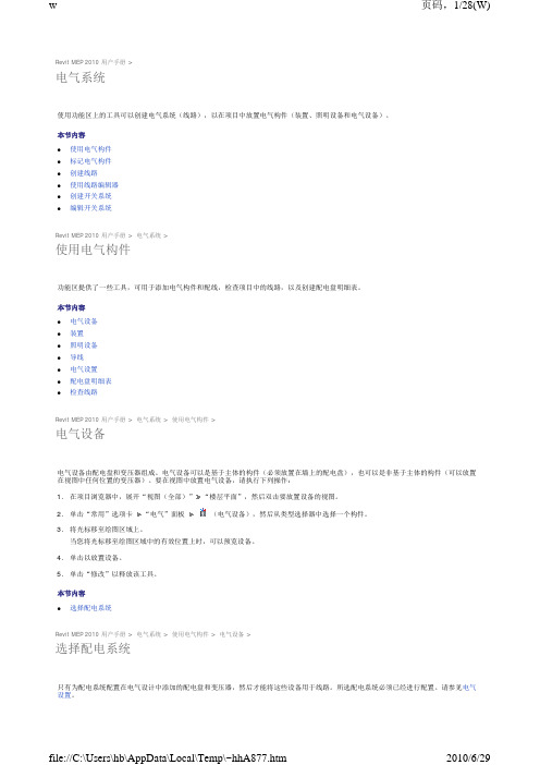
5. 单击以指定导线回路的起点。 6. 将光标移动到要连接的构件中间的某个点,然后单击以指定中点。
7. 将光标移动到下一个构件上,然后单击连接件捕捉以指定导线回路的终点(如下所示),或者单击绘图区域的开放区域以指定终点。
8. 单击“修改”以释放该工具。 配线对话框中指定了显示在配线回路上的记号的样式。
导线尺寸
导线尺寸窗格针对 Revit MEP 可用的导线类型提供信息。右侧窗格列出导线类型,这些导线类型基于材质、额定温度(60 摄氏度、75 摄氏度和 90 摄氏度)以及绝缘层类型。“校正系数”和“地线”分支列出校正系数(基于环境温度)和地线尺寸的载流量。
导线尺寸表列出给定导线材质、额定温度和绝缘层类型的组合当前可使用的导线尺寸。每个材质、额定温度和绝缘层类型组合都与一个单 独的导线尺寸表相关联。每当创建新的属性(材质、额定温度或绝缘层类型)时,都会同时为该属性创建一个新的尺寸表。每个尺寸都显 示了载流量、AWG(美国线规)尺寸以及项目中的可用导线的直径。Revit MEP 计算线路的导线尺寸(基于线路的额定电流)以使电压降 保持在低于 3% 的水平上。
1. 在项目浏览器中,展开“视图(全部)” “楼层平面”,然后双击您想要放置照明设备的视图。
2. 单击“常用”选项卡 “电气”面板
(照明设备),然后从类型选择器中选择一个构件。
3. 将光标移至绘图区域上。 当您将光标移至绘图区域中的某一有效主体或位置上时,可以预览照明设备。
4. 单击以放置照明设备。 5. 单击“修改”以释放该工具。
单击“值”列,单击 ,然后选择“是”将此功能应用于记号。如果您选择“否”,则显示为地线指定的记号。 z 显示记号 - 指定是始终隐藏记号、始终显示记号还是只为回路显示记号。 本节内容 z 导线尺寸 z 配线类型