COVNA-PVC Solenoid Valve Specification
医用外科口罩出口欧盟的包装标准
医用外科口罩出口欧盟的包装标准一、欧盟医疗器械包装法规与标准欧盟对于医疗器械的包装和标签有着严格的规定,以确保产品的安全性和有效性。
这些规定主要基于欧盟医疗器械指令(93/42/EEC)和相关法规,如欧洲药典(Ph.Eur.)和各成员国的国家标准。
二、医用外科口罩概述医用外科口罩主要用于医疗环境中,为医务人员和病人提供防护,阻止病原体通过口鼻传播。
其材质多为三层或多层无纺布,外层有防水功能,内层则具有良好的吸湿性。
规格尺寸需根据欧洲标准或各国国家标准制定。
三、包装要求1.标签:医用外科口罩的包装上应明确标明产品名称、型号、生产商、注册号等信息。
同时,还需注明欧盟CE认证标志和相关的安全警示语。
2.说明书:包装内应附有详细的说明书,内容包括使用方法、注意事项、维护与保养等信息,以便消费者正确使用产品。
3.安全认证标志:产品包装上应有欧盟CE认证标志,表明产品符合相关法规和标准要求。
四、法规遵从性对于医用外科口罩出口欧盟,企业需确保产品符合相关法律法规和标准要求。
这包括但不限于:欧盟医疗器械指令、欧洲药典以及各成员国的国家标准。
同时,企业还需获得欧盟授权机构的CE认证,以确保产品的安全性和有效性。
五、包装检测方法针对医用外科口罩出口欧盟的包装检测,主要涉及以下几个方面:1.标签检测:检查标签是否符合规定要求,包括内容、格式、位置等。
2.说明书检测:检查说明书是否完整、易读,是否包含必要的信息。
3.安全认证标志检测:确认欧盟CE认证标志是否清晰可见,是否符合规定要求。
4.整体检测:对整个包装进行外观、尺寸、结构等方面的检测,确保其符合标准要求。
六、解决方案与建议为确保医用外科口罩顺利进入欧洲市场,企业可采取以下措施:1.深入了解欧盟医疗器械包装法规与标准要求,确保产品包装符合规定。
2.建立完善的质量管理体系,确保产品质量和安全。
3.选择具备资质的欧盟授权机构进行CE认证,提高产品的合规性。
4.加强与进口商、经销商的沟通与合作,确保产品在欧洲市场的顺利推广。
SOLENOID VALVES 产品名说明书
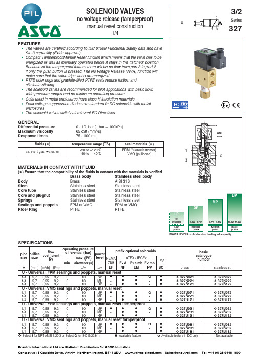
USOLENOID VALVESno voltage release (tamperproof)manual reset construction1/4213FEATURES• The valves are certified according to IEC 61508 Functional Safety data and have SIL-3 capability (Exida approval)• Compact Tamperproof/Manual Reset function which means that the valve has to be energized as well as manually operated before it stays in the "latched" position. Because of the tamperproof feature there will be no flow from port 3 to port 2 if only the push button is pressed. The No Voltage Release (NVR) function will make sure that the valve trips when de-energized• The solenoid valves are recommended for pilot applications with basic flow, wide pressure ranges and no minimum operating pressure• PTFE rider rings and graphite-filled PTFE seals reduce friction and eliminate sticking• Coils used in metal enclosures have class H insulation materials• Peak voltage suppression diodes are standard in DC solenoids with metal enclosures• The solenoid valves satisfy all relevant EC DirectivesGENERALDifferential pressure 0 - 10 bar [1 bar = 100kPa]Maximum viscosity 65 cSt (mm 2/s)Response times75 - 100 msfluids (✶)temperature range (TS)seal materials (✶)air, inert gas, water, oil-20 to +120°C -40 to + 40°CFPM (fluoroelastomer)VMQ ((sillicone)MATERIALS IN CONTACT WITH FLUID(✶) Ensure that the compatibility of the fluids in contact with the materials is verifiedBrass bodyStainless steel body Body Brass AISI 316Stem Stainless steel Stainless steel Core tube Stainless steel Stainless steel Core and plugnut Stainless steel Stainless steel Springs Stainless steel Stainless steel Sealings and poppets FPM or VMQFPM or VMQ Rider Ring PTFEPTFEPOWER LEVELS - cold electrical holding values (watt)SPECIFICATIONSpipe size orificesizeflowcoefficientKv operating pressuredifferential (bar)powerlevel prefix optional solenoidsbasic catalogue numbermin.max. (PS)NEMA 7&9ATEX / IECExIP65air/water (✶)Ex d Ex e mb Ex mb(mm)(m 3/h)(l/m)~/=~/=EF NF EM PV SC brass stainless st.U - Universal, FPM sealings and poppets, manual reset1/45,70,559,2010BP ●●●❍● 327B021 327B0221/45,70,559,2010MP -●●-● 327B221 327B2221/45,70,559,2010RP -●●-● 327B121 327B122U - Universal, VMQ sealings and poppets, manual reset1/45,70,559,2010BP ●●●❍● 327B071 327B0721/45,70,559,2010MP -●●-● 327B271 327B2721/45,70,559,2010RP -●●-● 327B171 327B172U - Universal, FPM sealings and poppets, manual reset tamperproof1/45,70,559,2010BP ●●●❍● 327B031 327B0321/45,70,559,2010MP -●●-● 327B231 327B2321/45,70,559,2010RP -●●-● 327B131 327B132U - Universal, VMQ sealings and poppets, manual reset tamperproof1/45,70,559,2010BP ●●●❍● 327B081 327B0821/45,70,559,2010MP -●●-● 327B281 327B2821/45,70,559,210RP-●●-●327B181327B182Select 8 for NPT ANSI 1.20.3 or Select G for ISO G(228/1)● Available feature ❍ Available feature in DC only- Not available3/2Series327Pneutrol International Ltd are Platinium Distributors for ASCO NumaticsContactus:5CaulsideDrive,Antrim,NorthernIreland,*************************************************:+44(0)2894481800PRODUCT SELECTION GUIDESTEP 1Select basic cataloguenumber,including pipe thread indentification letter. Refer to the specifications table on page 1.Example: 8327B021STEP 2Select prefix (combination). Refer to the specifications table on page 1 and the prefix table on page 2, respect the indicated power level.Example: NFSTEP 3Select suffix (combination) if required. Refer to the suffix table on page 2, respect the indicated power level.Example: COSTEP 4Select voltage. Refer to standard voltages on page 3.Example: 230V / 50/60 Hz STEP 5Final catalogue / ordering number. Example:NF 8327B021 CO 230V / 50/60 HzPREFIX TABLEprefix description power level 1234567LP RP MP BPE F Explosionproof - NEMA 7, 9 - Zinc plated steel conduit ---●E V Explosionproof - NEMA 7, 9 - 316 SS conduit ---●E M Waterproof IP67 - Metal enclosure (EN/IEC 60079-7+18, 61241-1)*-●●●E T Threaded conduit/hole (M20 x 1,5)-●●●I S S C Intrinsically safe with SC coil (EN/IEC 60079-11+26, 61241-11)*----N F Flameproof - Aluminium (EN/IEC 60079-1, 60079-31)*-●●●P V Encapsulated epoxy moulded (EN/IEC 60079-18, 61241-18)*---❍S C Solenoid with spade plug connector (EN/IEC 60730)-●●●W P Waterproof IP67 - Metal enclosure -●●●W P I S I.S. with Metal IP67 enclosure (EN/IEC 60079-11+26, 61241-11)*----W S Waterproof IP67 - 316 SS enclosure -●●●W S E M Waterproof IP67 - 316 SS enclosure (EN/IEC 60079-7+18, 61241-1)*-●●●W S I S I.S. with 316 SS IP67 enclosure (EN/IEC 60079-11+26, 61241-11)*----WS N F Flameproof - 316 SS (EN/IEC 60079-1, 60079-31)*-●●●T Threaded conduit (1/2" NPT)-●●●H C Class H - Battery charging circuit ---●H T Class H - High temperature----X Other special constructions-●●●SUFFIX TABLEsuffix descriptionpower level 12345LP RP MP BP E EPDM (ethylene-propylene)----J CR (chloroprene)----N Oxygen service (CR (chloroprene))----N V FPM (fluoroelastomer) and parts cleaned for oxygen service -●●●C O Epoxy coating on all external surfaces -●●●M BMounting bracket----M O Push type manual operator -●●●M S Screw type manual operator (1)-●●●MMetering device----● Available feature ❍ Available feature in DC only- Not available * A TEX solenoids are also approved according to EN 13463-1 (non electrical valves) (1)Functional Safety certification is not applicable with this featureOPTIONS & ACCESSORIEScatalogue number spare part kit no.(2)mounting bracket ~ / =SC 327B021C123670⏹SC 327B022C123670⏹SC 327B031C131237⏹SC 327B032C131237⏹SC 327B071C117644⏹SC 327B072C117644⏹SC 327B081C117645⏹SC 327B082C117645⏹SC 327B121C132251⏹SC 327B122C132251⏹SC 327B131C132253⏹SC 327B132C132253⏹SC 327B171C117646⏹SC 327B172C117646⏹SC 327B181C117647⏹SC 327B182C117647⏹SC 327B221C132251⏹SC 327B222C132251⏹SC 327B231C132253⏹SC 327B232C132253⏹SC 327B271C117648⏹SC 327B272C117648⏹SC 327B281C117649⏹SC 327B282C117649⏹Select 8 for NPT ANSI 1.20.3 or select G for ISO G(228/1)(2)Standard prefixes/suffixes are also applicable to kits ⏹ Mounting holes in bodyORDERING EXAMPLES VALVES:SC 8327B 02124V /DC WSEMT G 327B 022CO24V /DCNFET G 327B 021230V /50/60 Hz WSEMG 327B 02224V /DC NF 8327B 231CO 24V /DC WS G 327B 021CO 24V /DCEM 8327B 221230V /50/60 Hz PV 8327B 032CO 24V /DCEFG327H 022CO240V /50/60 Hzprefix (3)pipe thread voltage basic number (3)suffixORDERING EXAMPLES KITS:C131237(4)PV C123670NF C131237WSEM C123670prefixsuffixbasic number(3)Prefix EF and EV should always be used in conjunction withchange letter H in the basic number (4)Basic kit number applies to SC coil constructionPneutrol International Ltd are Platinium Distributors for ASCO NumaticsContactus:5CaulsideDrive,Antrim,NorthernIreland,*************************************************:+44(0)2894481800EXPLANATION OF TEMPERATURE RANGES OF SOLENOID VALVESValve temperature range The valve temperature range (TS) is determined by the selected seal material, the temperaturerange for proper operation of the valve and sometimes by the fluid (e.g. steam)Operator ambient temperature range The operator ambient temperature range is determined by the selected power level and thesafety codeTotal temperature range The temperature range of the complete solenoid valve is determined by the limitations of bothtemperature ranges aboveELECTRICAL CHARACTERISTICSCoil insulation class HElectrical safety IEC 335Standard voltages DC (=) 24V - 48V; Allowable voltage variation ± 10%AC (~) 24V - 48V - 115V - 230V/50/60Hz; Other voltages are available on requestprefix optionpower ratings operatorambienttemperaturerangesafety codeelectricalenclosureprotection(EN 60529)replacement coil / kittype(2) inrush holding hot/cold~~=~=(VA)(VA)(W)(W) (C°)(1)230V/50/60 Hz24V/DCBasic power (BP)SC10,010,010,09,0/11,2-40 to +55EN 60730IP65, moulded123664-017400425-14201 WP/WS10,010,010,09,0/11,2-40 to +55EN 60730IP67, steel /SS400915-017400913-14203 NF/WSNF10,010,010,09,0/11,2-60 to +40/60II2G Ex d IIC Gb T6/T5, II2D Ex t IIIC Db IP67, alu./SS 400915-017400913-14205 EM/WSEM10,010,010,09,0/11,2-40 to +40II2G Ex e mb II T3, II2D Ex tD A21IP67, steel /SS 400915-017400913-14203 PV---9,0/11,2-40 to +55II2G Ex mb II T4, II2D Ex mD 21IP67, moulded- - (3)06 EF/EV12,012,012,09,3/11,6-40 to +52/40NEMA type 7 and 9NEMA 4X276002-058D238714-006D07 Medium Power (MP)SC5,85,85,85,2/5,7-40 to +90EN 60730IP65, moulded400924-297400923-44202 WP/WS5,85,85,85,2/5,7-40 to +90EN 60730IP67, steel /SS400921-297400914-44204 NF/WSNF5,85,85,85,2/5,7-60 to +60/75/90II2G Ex d IIC Gb T6/T5/T4, II2D Ex t IIIC Db IP67, alu./SS 400921-297400914-44205 EM/WSEM5,85,85,85,2/5,7-40 to +40/75/90II2G Ex e mb II T5/T4/T3, II2D Ex tD A21IP67, steel /SS400921-297400914-44204 Reduced Power (RP)(4)SC3,73,73,73,2/3,6-40 to +55EN 60730IP65, moulded - (4)400923-04202 WP/WS3,73,73,73,2/3,6-40 to +55EN 60730IP67, steel /SS - (4)400914-24204 NF/WSNF3,73,73,73,2/3,6-60 to +60II2G Ex d IIC Gb T6, II2D Ex t IIIC Db IP67, alu./SS - (4)400914-24205 EM/WSEM3,73,73,73,2/3,6-40 to +40/55II2G Ex e mb II T6/T5, II2D Ex tD A21IP67, steel /SS - (4)400914-24204 (1) Temperature range can be limited by sealings(2) Refer to the dimensional drawings on page 4 and 5(3) Multiple coil kits are available under ATEX/IECEx, contact us (4) AC (~) limited to 127V/50/60Hz or 125V/DC- Not availableELECTRICAL CONNECTIONSprefix connectionSC Spade plug connector with cable gland EN175301-803A (ISO 4400) for cables with an outer dia-meter from 6 to 10 mmWP, WS, EM, WSEM M20 cable gland for cables with an outer diameter from 7 to 12 mm. With an internal and external facility for an earthing or bonding conductorNF, WSNF1/2" NPT threaded cable entry. Enclosures are supplied without cable glandNFET, WSNFET M20 x 1,5 threaded cable entry. Enclosures are supplied without cable glandPneutrol International Ltd are Platinium Distributors for ASCO NumaticsContactus:5CaulsideDrive,Antrim,NorthernIreland,*************************************************:+44(0)2894481800ADDITIONAL OPTIONS●Ex mb/mD (prefix "PV") solenoid can be supplied with various cable lengths ●Compliance with "UL", "CSA" and other local approvals available on request ●Manual Reset constructions suitable for -40°C are available on requestINSTALLATION●Multi language installation/maintenance instructions are included with each valve ●The solenoid valves can be mounted in any position without affecting operation ●The mounting holes are provided in the valve body●Threaded pipe connection identifier is 8 = NPT (ANSI 1.20.3); G = G (ISO 228/1)●Declarations of conformity are available on request●Ex e mb Prefix "EM" execution: solenoid enclosure has a cable gland with integral strain relief for cables with an o.d.from 7 to 12 mm and is provided with an internal and external connection facility for an earthing or bonding conductor ●Ex d Prefix "NF/WSNF" enclosure is provided with a 1/2" NPT threaded entry hole, M20 x 1,5 (prefix "ET") is optional Both are supplied without cable gland●All DC solenoids with metal enclosure are provided with switch-off peak voltage suppression diodes●T o comply with IEC 61508 (SIL) the valves must be provided with a specific exhaust protector (as shown on page 6) or equalDIMENSIONS (mm), WEIGHT(kg)TYPE 01:TYPE 02:Epoxy mouldedSC: IEC 335 / ISO 4400Epoxy mouldedSC: IEC 335 / ISO 4400327B021 / B022 / B031 / B032327B121 / B122 / B131 / B132 / B221 / B222 / B231 / B232TYPE 03:TYPE 04:Metal, epoxy coated / AISI 316 SS WP / WS: IEC 335EM / WSEM: EN/IEC 60079-7+18, 61241-1Metal, epoxy coated / AISI 316 SS WP / WS: IEC 335EM / WSEM: EN/IEC 60079-7+18, 61241-1327B021 / B022 / B031 / B032327B121 / B122 / B131 / B132 / B221 / B222 / B231 / B232Pneutrol International Ltd are Platinium Distributors for ASCO NumaticsContactus:5CaulsideDrive,Antrim,NorthernIreland,*************************************************:+44(0)2894481800DIMENSIONS (mm), WEIGHT(kg)TYPE 05:TYPE 06:Aluminium, epoxy coated / AISI 316 SS NF / WSNF: EN/IEC 60079-1, 60079-31Epoxy encapsulatedPV: EN/IEC 60079-18, 61241-18327 B 021 / B022 / B031 / B032 / B121 / B122 /327B131 / B132 / B221 / B222 / B231 / B232327B001 / B002 / B011 / B012ABC DEFG H KJ1223Ø5,52741159L1/2 NPTABCD EF G HKJ1223Ø5,52741LTYPE 07:Epoxy encapsulatedEF and EV: NEMA type 7, 9 / ICS-6 ANSI327H021 / H022 / H031 / H032ABCD EF GHKJ1223Ø5,52741type prefix/option power level A B C D E F G H J K L M N weight 01SC BP 45302479138155918550305527671,20 kg 02SCMP/RP 5030249814995915633552786-1,30 kg 03WP , WS, EM, WSEM BP 7730249815512081552786---1,20 kg 04WP , WS, EM, WSEM MP/RP 77302410115812081552789---1,30 kg 05NF , WSNF BP/MP/RP 97302412510254558817627113--2,70 kg 06PV BP 45302486137726745552774--1,20 kg 07EF , EVBP503024871387751552775---1,20 kgPneutrol International Ltd are Platinium Distributors for ASCO NumaticsContactus:5CaulsideDrive,Antrim,NorthernIreland,*************************************************:+44(0)2894481800EXHAUST PROTECTOR ORDER NUMBERS¼ISO 228/1brass/nickelB-MV110014NPT B-PV110014ISO 228/1stainless steelB-VX110014NPTB-PV110014 InoxEXHAUST PROTECTOR213SECTIONAL DRAWINGExecution : Reduced Power TamperproofPneutrol International Ltd are Platinium Distributors for ASCO NumaticsContactus:5CaulsideDrive,Antrim,NorthernIreland,*************************************************:+44(0)2894481800。
卡莫奇系列NA型阀门和电磁阀产品说明书
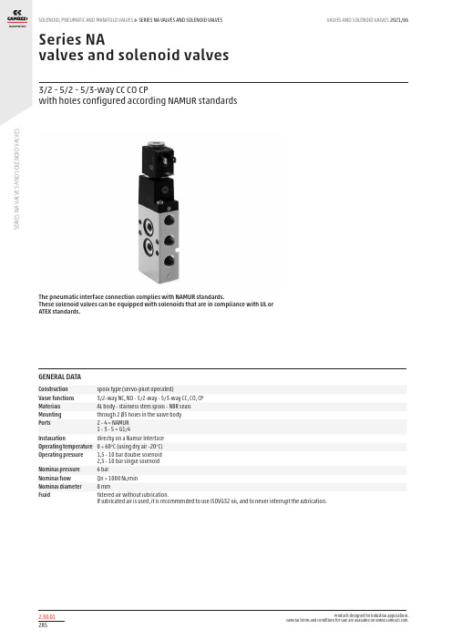
S E R I E S N A V A L V E S A N D S O L E N O I D V A L V E SSeries NAvalves and solenoid valves3/2 - 5/2 - 5/3-way CC CO CPwith holes configured according NAMUR standardsThe pneumatic interface connection complies with NAMUR standards.These solenoid valves can be equipped with solenoids that are in compliance with UL or ATEX standards.GENERAL DATAConstruction spool type (servo-pilot operated)Valve functions 3/2-way NC, NO - 5/2-way - 5/3-way CC, CO, CP Materials AL body - stainless steel spool - NBR seals Mounting through 2 Ø5 holes in the valve body Ports 2 - 4 = NAMUR 1 - 3 - 5 = G1/4Installation directly on a Namur Interface Operating temperature 0 ÷ 60°C (using dry air -20°C)Operating pressure 1,5 - 10 bar double solenoid 2,5 - 10 bar single solenoid Nominal pressure 6 barNominal flow Qn = 1000 Nl/min Nominal diameter 8 mmFluidfiltered air without lubrication.If lubricated air is used, it is recommended to use ISOVG32 oil, and to never interrupt the lubrication.S E R I E S N A V A L V E S A N D S O L E N O I D V A L V E SCODING EXAMPLETYPES OF MANUAL OVERRIDEExample of solenoid valve with a bistable standard manual override.Example of solenoid monostable valve (IM) and bistable valve with a lever type manual override (IL).S E R I E S N A V A L V E S A N D S O L E N O I D V A L V E S5/2-way solenoid valve, monostableS E R I E S N A V A L V E S A N D S O L E N O I D V A L V E S5/2-way, solenoid valve, bistableS E R I E S N A V A L V E S A N D S O L E N O I D V A L V E S5/2-way pneumatic valve, bistableS E R I E SN A VA LV E S A N D S O L E N O ID V A L VE S5/2-way pneumatic valve, monostable5/3-way pneumatic valve CC CO CPSingle subbase Mod. NA54-PCDistance plate for the mounting of Series H8 solenoidsSupplied with: 2x screws 2x O-rings。
进口阀门技术规格书中英文对照
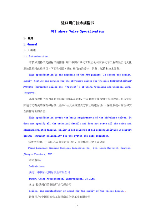
进口阀门技术规格书Off-shore Valve Specification1.总则1.General1.1 概述1.1 Introduction本技术规格书是招标书的附件,用于中国石油化工集团公司南京化学工业有限公司大化肥装置原料改造项目(下简称项目)进口阀门的的设计、供货、试验和技术服务。
This specification is the appendix of the RFQ package. It covers the design, supply, testing and service for the off-shore valves for the NCIC FEEDSTOCK REVAMP PROJECT (hereafter called the “Project”) of China Petroleum and Chemical Corp. (SINOPEC).本技术规格书所列是对进口阀门的基本要求,并未对所有技术细节作出规范,也未完全陈述与之有关的规范和标准,且并不因此而减轻卖方在正确进行设计、保证系统可靠性和安全操作方面的责任。
This specification covers the basic requirements of the off-shore valves. It does not specify all the technical details and does not state all the codes and standards related therein. Seller is not relieved of his responsibilities in correct design, ensuring reliability for the system and safe operation.装置所在地:中国江苏省南京市六合区,南京化学工业有限公司Plant Location: Nanjing Chemical Industrial Co., Ltd. Liuhe District, Nanjing, Jiangsu Province, PRC.术语解释:Definitions:买方: 中国石化国际事业有限公司Buyer:China Petrochemical International Co.,Ltd.卖方:提供阀门的制造厂或代理公司Seller:The manufacturer or agent for the supply of the valves herein.。
隔离器,灌装机,夹套等中英对照

dispersion equipment heat exchangers pulse pause ACC DIN CAD CAM auto clavable SOP ambient temperature steam temperature syringable HIGH PURITY BALL VALVES heavy body full passage brosilicate PTEE diaphragms soda lime glasses quick couple female thread platinum Platinum Cured silicone tube standard features handweel PTFE(TEFLON) available upon request semiconductor silicone rubber medical guide tube
限束孔径小孔操作面板上料侧操作面板卸料侧料斗普通胶塞铝盖isolator隔离器pathogenicmicroorganismswatervapourseparationcontinuum隔离连续体sterilitytesting无菌状态的检测asepticfilling无菌灌装asepticprocessing无菌操作reactor反应器blender搅拌器tableting压片toxicdispensingcontainmentisolator密封隔离器aspeticisolator无菌隔离器downflowbooth负压称量罩flowpatternlaminarflow层流turbulentflow紊流screwininletfilter拧入式进气过滤器inhouse内部的内行的dispensingsamplingsievingblendingchargingapiadditionmixinggranulationcentrifuge离心机freezedryeroffloadpackoff冷冻干燥器卸载filterdryeroffloadpackoff过滤干燥卸载millingmicronisingtabletting压片finalpackingblisterpackintermediate中间体stirrer搅拌器condenser电容器thermostatcontrol恒温器控制evaporator蒸发器reactorvessel反应器容器blisterpacking透明包装samplingshowcase展示inputoutputdistributedcontrolsystemdcscontainedtransfersystemctswipworkproducthallmarkiso146441cleanroomassociatedcontrolledenvironment洁净室及相关受控环境fs209eairborneparticulatecleanliness空气微粒洁净cgmpguidelinescurrentgoodmanufacturingpractices现行良好生产规范ispeguidelinesmedicaldeviceprofessionals食品药品监管mcamedicalcontrolagencyamericangloveboxsocietyguidelines美国手套箱协会应用程
皂液器 欧洲 标准

皂液器欧洲标准
欧洲对于皂液器的标准主要涉及到安全性和环保方面,具体标准如下:
1. EN 1040:用于细菌和真菌的消毒性能测试标准。
这个标准通常适用于皂液器,因为皂液用于卫生目的。
2. EN 1500:用于手部卫生的手部消毒剂的测试标准。
如果您的皂液器用于手部卫生,可能需要符合这个标准。
3. EN 1276:食品、工业和家庭用途的细菌灭活剂的基本要求标准。
4. EN 1499:在医疗场所使用的手部消毒剂的基本要求标准。
5. EN 1498:用于外科手术手部消毒剂的基本要求标准。
6. EN 55014-1和EN 55014-2:这是欧盟的CE测试标准,涉及到电磁兼容性和辐射方面的要求。
7. EN 60335:这是欧盟的CE测试标准,涉及到家用和类似用途电器的安全性。
此外,根据欧盟的相关法规,皂液器必须符合欧盟委员会规定的包装和包装废弃物处理的指令。
这些指令包括对包装材料的限制和要求,以确保其对环境的影响最小化。
此外,欧盟还对包装的可回收性和可持续性提出了要求,以减少包装废弃物对环境造成的负面影响。
以上信息仅供参考,建议咨询专业人士获取更准确的信息。
制表:审核:批准:。
Series SV电动阀寿命指南说明书

CALL TO ORDER: U.S. Phone 219 879-8000 • U.K. Phone (+44) (0)1494-461707 • Australia Phone (+61) (0) 2 4272 2055521S eries S V S olenoid Valve wi ll electri cally operate pneumati c actuators for on-off applications. When the solenoid valve receives the electrical input signal it switches the pneumatic supply pressure to the actuator, which moves the valve from the closed to open position. The next impulse to the solenoid valve will make the valve move back to the closed position. The low cost solenoid valve directly mounts onto pneumatic actuators with standard NAMUR mounting configuration eliminating external tubing and fittings. Buna-N O-rings are included to seal the valve ports to the side of the actuator. Standard features nclude a manual overri de, safety posi ti on by mechani cal spri ng, and a NEMA 4X enclosure. Direct mounts onto D, S, J, F, C, DA, or SR actuators.SPECIFICATIONSPower Requirements:120 VAC, 240 VAC, 24 VAC, 24 VDC, or 12 VDC.Supply Pressure:20 psi (1.4 bar) to 120 psi (8.3 bar).Air Connections:1/4˝ female NPT.Temperature Limits:-40 to 140°F (-40 to 60°C).Electrical Connections:Screw terminal.Conduit Connection:1/2˝ female NPT.Enclosure Rating:NEMA 4X.Mounting:NAMUR VDI/VDE 3845.Standard Features:Manual override, mechanical spring safety position.Optional Features:Other power voltages.Series SV3Solenoid ValveDirect Mounts to NAMUR Pneumatic ActuatorsSeries PVSolenoid Pilot ValveLow Cost, Compact Design, For Use with SAV Angle Seat ValvesThe Series PV three-way normally closed electro-pneumatic solenoid pilot valve can be di rect mounted to operate the Series SAV Angle Seat Valve actuators. When the solenoid valve receives the electric input signal, it switches the pneumatic supply pressure to the actuator, which moves the valve from the closed to open position, or reversely for normally open valves. When the input to the solenoid valve stops, the pneumatic supply pressure is again blocked, and the valve returns to the normal position. Suitable for use with air or other inert gases, the valve is supplied with a DIN connector, and is fitted with a manual override. Water can also be used as a pilot media provided that a suitable drain line is attached to the exhaust outlet. Select the proper model according to the SAV valve actuator diameter and power requirements.SPECIFICATIONSPilot Media: Air, water, or inert gases.Power Requirements:See model chart.Wetted Materials:Body: Niploy coated brass; Seal: FKM.Maximum Supply Pressure:150 psig (10.3 bar).Temperature Limits:14 to 140°F (-10 to 60°C).Actuator Connection: PV1_: 1/8˝ BSP; PV2_, PV3_: 1/4˝ BSP .Pilot Media Connection:1/8˝ NPT.Coil Consumption:PV1_, PV2_: AC: 9A (res.), 14A (ind.); DC: 6A; PV3_: AC: 15A (res.), 30A (ind.); DC: 10A.Mounting:Banjo connection.Enclosure Rating:IP65 (with DIN connector).Standard Features:Manual override, DIN connector.b Items are subject to Schedule B discounts.。
Series Typ Solenoid Valve 10bar-16 12bar, -10C to
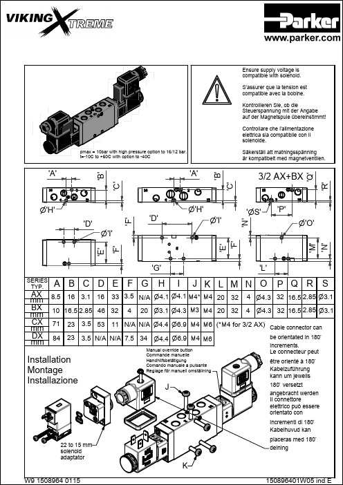
'G'
'L'
A SERIES TYP.
BC
DE
FG
H
I
JK LMN O PQ R S
mAXm 8.5 16 3.1 16 33 3.5 N/A 4.1 4.1 4* 4 20 32 4 4.3 32 16.5 2.85 3.1
BX mm
10 16.5 2.85 46 32
4
20 3.1 4.3 3 4 20 32 4 4.3 32 16.5 2.85 3.1
Le valvole possono essere utilizzate senza lubrificazione. Se utilizzata consigliamo i seguenti olii lubrificanti.
Ventilen kan användas utan tillsatssmörjning.Om tillsatssmörjning används rekommenderas följande oljor.
FOR THE INTERNAL MAINTENANCE OF THE VALVE
= Lubricate with grease (available
in 250ml tin Part No. 3099) = Lubrifier avec graisse (disponible
T1
en 250ml REF. 3099)
22 to 15 mm solenoid adaptator
placeras med 180 delning
K
W9 1508964 0115
150896401W05 ind E
Installation - Anschluss - Installazione
双杆阀值系列说明书

Double solenoid valve DN 40 - DN 125 nominal diameters DMV-D/11DMV-DLE/117.31Technical descriptionThe DUNGS double solenoid valve DMV integrates two solenoid valves in one com-pact fitting.- Automatic shut-off valves as per DIN EN 161 Class A Group 2.- Two A valves in one housing - Double seat valves - High flow rates - Max. operating pressure up to 0.5 bar - Fast closing - Fast opening (DMV-D/11) or slow open-ing (DMV-DLE/11) with adjustable fast stroke for start gas volume - Adjustable main volume - DC solenoid - Mountable closed position signal con-tact- Compact, light-weight ApplicationDouble solenoid valves are used where two single valves were mounted previously. In connection with DUNGS gas regulators and additional components, a wide varietyof regulating tasks can be performed.It does not contain any non-ferrous metals, suitable for gases of up to max. 0.1 vol.% H 2S, dry. Suitable for gases of families 1, 2, 3 and other neutral gaseous media.ApprovalsEC type test approval as per EC Gas Appli-ance Directive:DMV-…5040-5125/11 CE-0085 AN 2801EC type test approval as per EC Pressure Equipment Directive:DMV-…5040-5125/11 CE0036Approvals in other important gas consum-ing countries.P r i n t e d i n G e r m a n y • R ös l e r D r u c k • E d i t i o n 02.06 • N r. 218 376SpecificationsNominal diametersFlangeMax. operating pressureSolenoid valve V1Solenoid valve V2Closing timeOpening timeFast strokeMain valve restrictorMaterials of gas conveying parts Ambient temperatureInstallation positionDirt trapMeasuring gas connectionIgnition gas connectionVoltage/frequencyRating / power consumptionat 230 V AC, + 20°CDegree of protection / switch-on duration Electrical connectionRadio interferenceClosed position signal contact DN 40 50 65 80 100 125Connection flange as per DIN 2501 Part 1, to fit preweld flanges as per DIN 2633 (PN 16) DN 40 to DN 125, ISO 7005 - 1 (PN 16), ISO 7005 - 2 (PN 16) Construction length as per DIN 3202 Part 1, row F1 for DN 65 to DN 125500 mbar (50 kPa)Automatic shut-off valve as per EN 161: Class A, Group 2Automatic shut-off valve as per EN 161: Class A, Group 2< 1 sDMV-D…/11: < 1 sDMV-DLE…/11: approx. 20 s at room temperature +20°C and without fast stroke AdjustableAdjustableHousing: aluminium, steel, no non-ferrous metalsSeals at valve seat: NBR basis, suitable for gases as per G260/l-15 °C to +60 °CSolenoid vertically upright to lying horizontallySieve installed. To protect the complete gas train we recommend you to install an upstream gas filter (refer to Datasheet 2.03)G 1/4 DIN ISO 228 centrally upstream of V1 and downstream of V2G 1/8 DIN ISO 228 on both sides upstream of V1, between V1 and V2, downstream of V2G 3/4 ignition gas flange as per ISO 228, possible on both sides between V1 and V250 - 60 Hz, 220 V - 240 V AC, -15% +10%, further voltages on requestOther preferred voltages: 110 V - 120 V AC, 24 V - 28 V DCVersion Approx. rating [VA] Approx. operating current [A] DMV-D(LE) 5040/11 90 0.37DMV-D(LE) 5050/11 90 0.37DMV-D(LE) 5065/11 110 0.46DMV-D(LE) 5080/11 110 0.46DMV-D(LE) 5100/11 135 0.56DMV-D(LE) 5125/11 200 0.84IP 54 / 100 %PG* 11 cable gland, plug connection as per DIN EN 175301-803 on request (* = heavy-gauge conduit thread)Degree of interference NType K01/1 (DIN tested), can be mounted on V1 and V2Important: Always order,plug connection and system accessories separately.◆= standard (◆) = on request -- = not possibleSystem accessoriesThe double solenoid valve is prepared for direct mounting of DUNGS system accessories and additional equipment.Information on system acces-soriesVPS 504 valve proving system Datasheet 8.10Pressure limiter ÜB, NB...A2 for multiple actuatorsDatasheet 5.08If a system accessory isadded, it may not be pos-sible to mount further devices. Compact pressure switch for mul-tiple actuators GW…A5Datasheet 5.02K01/1 closed position signal con-tact to monitor closed position ofvalvesDatasheet 12.01We reserve the right to make any changes in the interest of technical progress.Double solenoid valve Flow diagram DN 40 - DN 125 nominal diameters DMV-D/11DMV-DLE/11Head Offices and FactoryKarl Dungs GmbH & Co. KG Siemensstraße 6-10D-73660 Urbach, Germany Telephone +49 (0)7181-804-0Fax +49 (0)7181-804-166Postal addressKarl Dungs GmbH & Co. KG Postfach 12 29D-73602 Schorndorf, Germany ********************Internet 。
pvc人造革相应标准
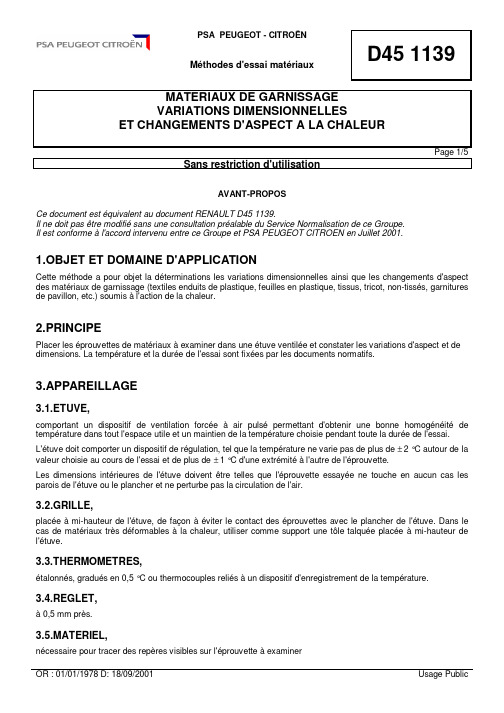
D451139Méthodes d'essai matériauxMATERIAUX DE GARNISSAGEVARIATIONS DIMENSIONNELLESET CHANGEMENTS D'ASPECT A LA CHALEURPage1/5Sans restriction d'utilisationAVANT-PROPOSCe document estéquivalent au document RENAULT D451139.Il ne doit pasêtre modifiésans une consultation préalable du Service Normalisation de ce Groupe.Il est conformeàl'accord intervenu entre ce Groupe et PSA PEUGEOT CITROEN en Juillet2001.1.OBJET ET DOMAINE D'APPLICATIONCette méthode a pour objet la déterminations les variations dimensionnelles ainsi que les changements d'aspect des matériaux de garnissage(textiles enduits de plastique,feuilles en plastique,tissus,tricot,non-tissés,garnitures de pavillon,etc.)soumisàl'action de la chaleur.2.PRINCIPEPlacer leséprouvettes de matériauxàexaminer dans uneétuve ventilée et constater les variations d'aspect et de température et la durée de l'essai sont fixées par les documents normatifs.3.APPAREILLAGE3.1.ETUVE,comportant un dispositif de ventilation forcéeàair pulsépermettant d'obtenir une bonne homogénéitéde température dans tout l'espace utile et un maintien de la température choisie pendant toute la durée de l'essai.L'étuve doit comporter un dispositif de régulation,tel que la température ne varie pas de plus de±2°C autour de la valeur choisie au cours de l'essai et de plus de±1°C d'une extrémitéàl'autre de l'éprouvette.Les dimensions intérieures de l'étuve doiventêtre telles que l'éprouvette essayée ne touche en aucun cas les parois de l'étuve ou le plancher et ne perturbe pas la circulation de l'air.3.2.GRILLE,placéeàmi-hauteur de l'étuve,de façonàéviter le contact deséprouvettes avec le plancher de l'étuve.Dans le cas de matériaux très déformablesàla chaleur,utiliser comme support une tôle talquée placéeàmi-hauteur de l'étuve.3.3.THERMOMETRES,étalonnés,gradués en0,5°C ou thermocouples reliésàun dispositif d'enregistrement de la température.3.4.REGLET,à0,5mm près.3.5.MATERIEL,nécessaire pour tracer des repères visibles sur l'éprouvetteàexaminer3.6.SALLE CONDITIONNEE,à23°C ±2°C et 50%±5%d'humiditérelative.3.7.MATERIEL DE DECOUPE,des éprouvettes tel que ciseaux non crantés ou emporte-pièce.4.PREPARATION DES EPROUVETTES4.1.PREPARATIONDans le cas de matériaux livrés en rouleau,prélever si possible,trois éprouvettes carrées de 300mm ou toute autre dimension indiquée dans les documents normatifs,de côtéparallèlement au sens longitudinal du matériau,àl'aide du matériel de découpe (3.7.).Ces prélèvements doivent être effectués àplus de 150mm des bords et des extrémités.Pour les textiles,les trois éprouvettes doivent être découpées selon le schéma ci-dessous,parallèlement au fil de chaîne pour les tissés et parallèlement àla colonne pour les tricots (droit fil,droit colonne).Dans le cas de panneaux prédécoupés,effectuer les prélèvements parallèlement au sens longitudinal du panneau qui sera référencésens 1.Lorsqu'il est impossible de prélever un carréde 300mm de côté,découper trois éprouvettes de 300mm x 100mm dans un sens référencé1et trois autres éprouvettes de dimension 300mm x 100mm dans un sens perpendiculaire qui sera référencé2.Dans le cas de matériaux livrés en rubans,prélever trois éprouvettes de longueur 300mm et de largeur égale àcelle du produit àl'état de livraison.4.2.CONDITIONNEMENTSur chaque éprouvette,tracer 2repères distants de 250mm,ou toute autre dimension indiquée dans les documents normatifs.A l'aide du matériel (3.5.),suivant l'Annexe figures 1et 2.Ces repères doivent être situés àéquidistance des bords ou des extrémités de l'éprouvette,suivant l'Annexe figures 1et 2,tolérance de ±0,5mm et acceptés pour le tracédes repères.Après un conditionnement de 24heures ±2heures dans la salle conditionnée (3.6.),ces repères sont tracés sur les éprouvettes.Dans ce cas de matériaux auto-adhésifs,l'essai peut être pratiquésur des éprouvettes appliquées surle subjectile appropriéet dans les conditions finales d'utilisation.Sens L5.MODE OPERATOIRE•Porter l'étuve(3.1.)àla température indiquée dans le document normatif du matériau considéré.•Après stabilisation de cette température,mettre leséprouvettes dans l'étuve(3.1.)de façon qu'elles soientàplat,face envers sur la grille(3.2.),et en contact avec l'air chaud sur la plus grande surface possible.•Après22heures030+minutes,ou toute autre durée indiquée dans les documents normatifs,sortir les éprouvettes de l'étuve(3.1.)et les placeràplat dans la salle conditionnée(3.6.).Dans le cas de matériaux très déformableàla chaleur,les placer sur une surface lisse talquée.•Après un minimum de22heures ou toute autre durée indiquée dans les documents normatifs,mesurer les distances entre les repères.•Noter l'aspect deséprouvettes.6.EXPRESSION DES RESULTATS6.1.VARIATIONS DIMENSIONNELLESExprimer les variations dimensionnelles en pourcentage de la distance initiale entre repères,dans le sens longitudinal(sens1)et dans le sens transversal(sens2)sur chacune des3éprouvettes.Effectuer ensuite,les moyennes arithmétiques pour les sens1et2.Nota:La variation est affectée d'un signe"+"s'il y a allongement et d'un signe"-"s'il y a diminution de longueur. 6.2.CHANGEMENT D'ASPECTNoter tous les changements d'aspect du matériau:changement de la brillance,altération du grenage, boursouflures,exsudation,séparation des constituants,modification de géométrie,changement de tonalité,etc.7.PROCES-VERBAL D'ESSAIOutre les résultats obtenus,le procès-verbal d'essai doit indiquer:•la référence de la présente méthode,•les températures et durées retenues pour l'essai,•les références du matériau,•les modes de prélèvement du matériau,•les variations dimensionnelles(%)et les changements d'aspect,•les détails opératoires non prévus dans la méthode ainsi que les incidentséventuels susceptibles d'avoir agi sur les résultats.Annexe REPERES SUR EPROUVETTESFigure1-Cas généralFigure2-Cas particulier8.HISTORIQUE ET DOCUMENT CITES8.1.HISTORIQUE8.1.1.CREATION•OR:01/01/1978-CREATION DE LA NORME.8.1.2.OBJET DE LA MODIFICATION•D:18/09/2001MODIFICATIONS REDACTIONNELLES-Groupe de Travail PSA/RSA/RVI.•C:21/07/1997REPRISE SOUS IDEM.8.2.DOCUMENTS CITES8.2.1.DOCUMENTS PSA8.2.1.1.Normes8.2.1.2.Autres8.2.2.DOCUMENTS EXTERIEURS8.3.EQUIVALENT A:REND4511398.4.CONFORME A:8.5.MOTS CLEFS。
FESTO 2路小型切换阀门 VOVK 2d说明书

Solenoid valve VOVK2d /catalogue/... – 2023/01Solenoid valve VOVKCharacteristicsAtaglance • Miniature switching valve 3/2 NC• Optimized for very small installation spaces, with a width of only 5.9 mm • large pressure range of -0.9 .... 7 bar, therefore also vacuum-compatible • can be easily connected in series • very low power consumption of 0.5 W • with LED and overvoltage protection circuit•different variants 12, 24 V DC, with plug+cable (H5Z), or with pins (T1)PneumaticconnectionThere are three versions for the various applications:• [B3F], [B3.2F ] as individual valve with barbed connectors• [FB] with flanged connection at the bottom for mounting valves on a manifold duct plate• [FF] up to 20 valves that can be directly connected in series as a valve block, with barbed connector [B3]Barb fitting 3 mm[F]Flange/subbase• Individual valve, direct, with barbed connectors • Individual valves with flanged connectionConnectionorientation[B]Bottom[F]Front• VOVK-…-FB with flanged connection underneath• Manifold block for an individual valve or for ten valves• VOVK-..-FF with flanged connection on the front • For easy side-by-side installation of 2 … 20 valves• Working port with barbed connector for 3 mm or 4 mm O.D. tubing• Common supply and exhaust with barbed connectors for 6 mm O.D. tubingCircuitry[P]Protective circuitSolenoid valve VOVKType code32023/01 – d/catalogue/...Solenoid valve VOVKDatasheet4d/catalogue/...– 2023/01Solenoid valve VOVKDimensionsB1 B2 B3 H1 H2 H3 H4 H5VOVK-…-1H5ZP-B3F 9,4 6 5,9 15 15,5 4 4 2 VOVK-…-5H5ZP-B3FVOVK-…-1H5ZP-B3.2FVOVK-…-5H5ZP-B3.2FL1 L2 L3 L4 L5 L9 L10VOVK-…-1H5ZP-B3F 37,8 24,1 3,8 5 300 2,6 0,7 VOVK-…-5H5ZP-B3FVOVK-…-1H5ZP-B3.2FVOVK-…-5H5ZP-B3.2F5 2023/01 – d/catalogue/...Solenoid valve VOVKDimensionsB1 B2 B3 B4 B5 H1 H3 H4 H5VOVK-…-1T1P-B3F 9,4 6 5,9 2,5 0,5 15 4 4 2 VOVK-…-5T1P-B3FVOVK-…-1T1P-B3.2FVOVK-…-5T1P-B3.2FH6 H7 L1 L2 L3 L4 L6 L9 L10VOVK-…-1T1P-B3F 13,5 5 34 20,3 3,8 5 0,5 2,6 0,7 VOVK-…-5T1P-B3FVOVK-…-1T1P-B3.2FVOVK-…-5T1P-B3.2F6d/catalogue/...– 2023/01Solenoid valve VOVKDimensionsB3 B4 B5 H6 H7 L1 L2 L4 L6VOVK-…-1T1P-FF 5,9 2,5 0,5 13,5 5 29 20,3 0,9 0,5 VOVK-…-5T1P-FF7 2023/01 – d/catalogue/...Solenoid valve VOVKDimensionsB3 H6 L1 L2 L4 L5 L7VOVK-…-1H5ZP-FF 5,9 14 32,8 24,1 0,9 300 27 VOVK-…-5H5ZP-FF8d/catalogue/...– 2023/01Solenoid valve VOVK DimensionsB1 B2 B3 B6 D2H1 H6 H8 H9@VOVK-…-1H5ZP-FB 9,4 6 5,9 4,2 1 13,5 14 11,5 0,8 VOVK-…-5H5ZP-FBL1 L2 L3 L5 L7 L8 L9 L10 VOVK-…-1H5ZP-FB 32,4 24,1 3,8 300 26,6 4,9 2,9 1 VOVK-…-5H5ZP-FB9 2023/01 – d/catalogue/...Solenoid valve VOVKDimensionsH6 H7 B1 B2 B3 B4 B5 B6 D2@VOVK-…-1T1P-FB 9,4 6 5,9 2,5 0,5 4,2 1 13,5 5 VOVK-…-5T1P-FBH8 H9 L1 L2 L3 L6 L8 L9 L10 L11 VOVK-…-1T1P-FB 11,5 0,8 28,6 20,3 3,8 0,5 4,9 2,9 1 19,1 VOVK-…-5T1P-FB10d/catalogue/...– 2023/01B1 B2 B3 B4 D1 D2D3 D4 H1@VOVK-…-H5ZP-FB 14 9 4,5 5 M5x0,8 3,2 M2x0,4 M3x0,5 21 VABS-C12-6-B-M3H2 H3 H4 H5 H6 H7 L1 L2 L3 L4 VOVK-…-H5ZP-FB 10,5 6 4,2 14 3,5 10,5 20 11,8 4,7 3VABS-C12-6-B-M3H1 B1 B2 B3 B4 B5 D1 D2 D3 D4@VABM-C12-…20 15,3 8,2 3 37,8 M5x0,8 M3x0,5 M2x1,4 3,2 14 H2 H3 H4 H5 L1 L2 L3 L4 L5 L6 L7VABM-C12-…9 4,5 5 28,2 68 61 3,5 10,5 6 10,5 6B1 B2 D1H1 H2 L1 L2 L3@VABS-C12-6-S-B3 6 3,6 2,6 13,9 12,8 13,6 5 4,7VABS-C12-6-S-B4 6 3,6 3,3 13,9 12,8 13,6 5 4,7B1 B2 B3 B4 D1@D2@D3@H1VABS-C12-6-S 13 12,8 7,5 5,5 5,1 3,4 3,4 11,5 H2 H3 H4 L1 L2 L3 L4 VABS-C12-6-S 6 5,5 4,7 13 3,6 2,8 2,8Ordering dataIndividualvalvewithflangedconnectionfrontside IndividualvalvewithflangedconnectionunderneathAccessories。
万达流辊solenoide操作弹阀车身卡槽说明书
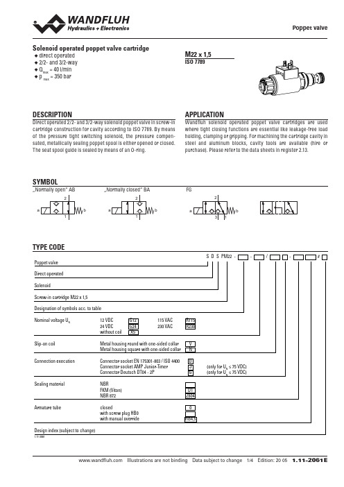
Solenoid operated poppet valve cartridge ◆direct operated◆2/2- and 3/2-way◆Q max = 40 l/min◆p max = 350 bar M22 x 1,5ISO 7789DESCRIPTIONDirect operated 2/2- and 3/2-way solenoid poppet valve in screw-in cartridge construction for cavity according to ISO 7789. By means of the pressure tight switching solenoid, the pressure compen-sated, metallically sealing poppet spool is either opened or closed. The seat spool guide is sealed by means of an O-ring. APPLICATIONWandfluh solenoid operated poppet valve cartridges are used where tight closing functions are essential like leakage-free load holding, clamping or gripping. For machining the cartridge cavity in steel and aluminum blocks, cavity tools are available (hire or purchase). Please refer to the data sheets in register 2.13.SYMBOL …Normally open“ ABb…Normally closed“ BAbFGaTYPE CODES D S PM22 - - / - # Poppet valveDirect operatedSolenoidScrew-in cartridge M22 x 1,5Designation of symbols acc. to tableNominal voltage UN 12 VDC G12 115 VAC R115 24 VDC G24 230 VAC R230 without coil X5Slip-on coil Metal housing round with one-sided collar VMetal housing square with one-sided collar N Connection execution Connector socket EN 175301-803 / ISO 4400 DConnector socket AMP Junior-Timer J (only for UN ≤ 75 VDC)Connector Deutsch DT04 - 2P G (only for UN≤ 75 VDC)Sealing material NBRFKM (Viton) D1NBR 872 Z604Armature tube closed 0with screw plug HB0with manual override HB4,5Design index (subject to change)1.11-2061GENERAL SPECIFICATIONSHYDRAULIC SPECIFICATIONSELECTRICAL SPECIFICATIONSNote!Other electrical specifications see data sheet 1.1-168 (slip-on coil V) and 1.1-175 (slip-on coil N)ACTUATIONSURFACE TREATMENT◆The cartridge body, the slip-on coil and the armature tube arezinc-nickel coatedSEALING MATERIALNBR or FKM (Viton) as standard, choice in the type codePERFORMANCE SPECIFICATIONSOil viscosity u = 30 mm 2/sHYDRAULIC CONNECTIONCavity drawing according to ISO 7789–22–01–0–98Note!For detailed cavity drawing and cavity tools see data sheet 2.13-1008HYDRAULIC CONNECTIONCavity drawing according to ISO 7789–22–04–0–98Note!For detailed cavity drawing and cavity tools see data sheet 2.13-1004SDSPM22Note!The switching times depend on the volume flow, pressure and viscosity. In case of very large volume flows, the switching time for closing can get consider-ably longer.PERFORMANCE SPECIFICATIONSOil viscosity u = 30 mm 2/sSTANDARDSINSTALLATION NOTESWandfluh AG Postfach CH-3714 FrutigenTel. +41 33 672 72 72 Fax +41 33 672 72 12 ******************PARTS LISTACCESSORIESMANUAL OVERRIDEScrew plug (HB0), no actuation possible Optionally: HB4,5, HN(K) or HR(K)→ See data sheet 1.1-311DIMENSIONSSDSPM22-AB / BASDSPM22-FG。
出口北美的卫生级快装蝶阀标准
出口北美的卫生级快装蝶阀标准近年来,随着全球化的加速和贸易自由化的推进,中国的出口业务在不断发展。
其中,卫生级快装蝶阀是一种重要的出口产品。
那么,出口北美的卫生级快装蝶阀标准是什么呢?1. 北美市场对卫生级快装蝶阀的要求在北美市场,卫生级快装蝶阀属于食品、制药和化妆品等行业的关键设备。
因此,该产品必须符合相关标准,如FDA和3A认证等。
此外,北美市场对卫生级快装蝶阀的要求还包括以下几点:(1) 常见的材质要求:SUS316L、304、304L等不锈钢、陶瓷等。
(2) 对表面光洁度的要求:内表面Ra不得低于0.8um,外表面Ra不得低于1.6um。
(3) 关键密封部位的要求:密封圈材质应符合FDA标准,且密封部位应设计得易于清洗,以满足卫生级要求。
(4) 对尺寸精度的要求:卫生级快装蝶阀的尺寸精度应符合ISO2852标准。
2. 卫生级快装蝶阀的结构和使用特点卫生级快装蝶阀有两种结构形式,分别为单片式和双片式。
其使用特点包括以下几个方面:(1) 快速开闭:卫生级快装蝶阀采用曲柄机构,开闭快速。
(2) 密封性好:卫生级快装蝶阀的密封性好,密封圈材质符合FDA标准,所以在常温到150℃的范围内都有良好的密封。
(3) 清洗方便:卫生级快装蝶阀因其结构简单,易于拆卸和清洗。
3. 卫生级快装蝶阀在北美市场的应用卫生级快装蝶阀在北美市场广泛应用于食品、制药和化妆品等行业。
以食品行业为例,卫生级快装蝶阀可用于饮料和液体食品的输送和调节。
在制药和化妆品行业中,卫生级快装蝶阀可以用于药液、洗剂、乳液等管道的控制。
总之,卫生级快装蝶阀是一种重要的出口产品,符合北美市场的相关标准和要求可以助力中国企业开拓更广阔的海外市场。
同时,了解卫生级快装蝶阀的结构和使用特点以及在北美市场的应用也可以帮助国内企业更好地进行产品设计和开发。
PVC技术参数

Bent at 20 degress celsius20摄氏度时弯折状态
No fissure无裂纹
Resistance to break withbitumen
100N/50mm
Behavior during drilling test钻孔测试状态
Appearance外观
No bubble, crack, adhesion and hole无气泡,裂纹,粘结和孔洞
Thickness厚度
1.2mm; 1.5mm; 2.0mm
**************************************************************************
海纳尔PVC卷材性能表Technical Data Sheet
项目Itห้องสมุดไป่ตู้m
測值Test Result
Tensile strength拉伸强度
≥ 16Mpa
Breaking Elongation断裂伸长率
≥ 285%
Compressive strength at 20% tension
2.5N/mm2minimum*
transverse3lowtemperaturebending低温弯折性25degreecelsiuscracking无裂纹waterabsorption1watervapourtransmission不透水性03mpa24hwaterimpermeability不透水bent20degresscelsius20摄氏度时弯折状态fissure无裂纹resistancebitumen100n50mmbehaviorduringdrillingtest钻孔测试状态750mmdroppdimensionalstabilityafteracceleratedaging加速老化尺寸变化率072variationtensilestrengthlongitudinal20variationfailurelongitudinal20servicelife使用年限40yearssolidplasticizer固体增塑剂20yearsliquidplasticizer液体增塑剂appearance外观bubblecrackadhesionhole无气泡裂纹粘结和孔洞thickness厚度12mm
【精品】国外阀门标准一览表

国外阀门标准一览表标准代号ISO 标准名称4126 安全阀的一般要求5208 工业用阀门的压力试验5209 一般工业用阀门的标志5210 Pt.1 多回转阀门驱动装置的连接件第一部分:法兰尺寸5210 Pt.2 多回转阀门驱动装置的连接件第二部分:法兰和接头的连接性能5210 pt.3 多回转阀门驱动装置的连接件第三部分:传动件的尺寸5211 pt.1 部分回转阀门驱动装置的连接件第一部分:法兰尺寸5211 pt.2 部分回转阀门驱动装置的连接件第二部分:法兰和接头的连接性能5211 pt.3 多回转阀门驱动装置的连接件第三部分: 传动件的尺寸5752 法兰管路系统中金属阀门的结构长度ISO 5996 铸铁制闸阀ISO 6002 阀盖用螺栓连接的钢制闸阀6552 自动蒸汽疏水阀的术语6553 自动蒸汽疏水阀的标志6554 法兰连接自动蒸汽疏水阀的结构长度6704 自动蒸汽疏水阀的分类6948 自动蒸汽疏水阀制造和使用特性试验7121 法兰和对焊接钢制球阀(第四次建议草案)7259 主要靠手柄操作的地下用铸铁制闸阀7841 蒸汽漏损试验标准代号BS 标准名称BS1212 固定球球阀(朴茨茅斯型)BS1123 储气罐和空压设备用安全阀,仪表和其他安全配件BS1414 石油,石油化学及有关工业用法兰和对焊接的楔式闸阀BS1552 低压煤气用调节旋塞阀BS1570 石油工业用法兰和对焊连接钢制旋塞阀(不包括井口阀和自喷阀)BS1735 石油工业用125磅级1.5''~24''法兰连接明杆楔式铸铁制闸阀BS1868 石油,石油化学及有关工业用法兰和对焊接连接钢制止回阀BS1873 石油,石油化学及有关工业用法兰和对焊接连接钢制截止阀和止回阀BS1952 一般用的铜合金制闸阀BS1953 一般用的铜合金制止回阀BS1968 铜合金制浮球式球阀BS2060 一般用螺纹连接铜合金制截止阀BS2080 石油,石油化学及有关工业用法兰和对焊接连接阀门的结构长度BS2591 PT.1 阀门和阀门零件术语第一部分:内螺纹连接的截止阀,止回阀和闸阀BS2591 PT.2 阀门和阀门零件术语第二部分:安全阀和保险阀BS2591PT.3 阀门和阀门零件术语第三部分:旋塞阀BS2591PT.4 阀门和阀门零件术语第四部分:蝶阀BS2591PT.5 阀门和阀门零件术语第五部分:球阀BS2995 石油工业用2''以下的螺纹和承口焊连接的铸钢和锻钢制闸阀,截止阀,止回阀和旋塞阀BS3464 一般用铸铁制闸阀BS3808 石油工业用2''以下法兰,螺纹和承口焊连接的铸钢和锻钢制楔式闸阀BS3948 一般用铸铁制平行式闸阀BS3952 一般用铸铁制蝶阀BS3961 一般用螺纹连接的铸铁制截止阀和截止止回阀BS4090 一般用铸铁制止回阀BS4133 一般用法兰连接的钢制平行式闸阀BS4312 一般用法兰连接的钢制截止阀和截止止回阀BS4460 石油工业用钢制球阀BS5146 石油,石油化学及有关工业用钢制阀门的检查和试验BS5150 一般用铸铁制楔式双闸板闸阀BS5151 一般用铸铁制平行闸阀BS5152 一般用铸铁制截止阀和截止止回阀BS5153 一般用铸铁制止回阀BS5154 一般用铜合金制截止阀,截止止回阀,止回阀和闸阀BS5155 一般用铸铁及碳素钢制蝶阀BS5156 一般用隔膜阀BS5157 一般用钢制平行闸阀BS5159 一般用铸铁和碳钢制球阀BS5160 一般用法兰钢制截止阀,截止止回阀和升降式止回阀BS5351 石油,石油化学和有关工业用钢制球阀BS5417 一般工业用阀门的试验BS5418 一般工业用阀门的标志标准代号ANSI标准名称A126阀门,法兰和管件的灰铸铁件A181一般用锻造或轧制钢法兰和锻造管件阀门及零件B16.10铁制阀门的结构长度B16.34钢制阀门B127.1恒液面油用阀门标准代号API标准名称SPEC6D API 6D (第16版)管路阀门规范附录1STD6D管路用钢制闸阀,旋塞阀,球阀和止回阀STD6D钻采用法兰连接的钢制闸阀和旋塞阀SPE14D海上平台用安全阀526法兰连接钢制安全阀527金属--金属密封安全阀的密封性528安全阀的铭牌529法兰连接可锻铸铁制旋塞阀594对夹式止回阀595法兰连接铸铁制闸阀597法兰或对焊连接钢制缩口闸阀598阀门的检查与试验599法兰或对焊连接钢制旋塞阀600炼油厂用法兰或对焊接钢制闸阀和旋塞阀602炼油厂用小型碳钢制闸阀603炼油厂用150磅薄壁耐腐蚀闸阀604法兰连接球墨铸铁制闸阀607软密封面球阀的耐火试验609蝶阀(<=150磅, <=150oF)标准代号ASTM标准名称A230阀门用油回火的碳素弹簧钢丝的质量标准A232阀门用铬钒合金钢质量标准A350低温用锻造或轧制碳素钢合金钢法兰锻造管件,阀门及零件A338可锻铸铁制法兰,管件和阀门A694高压输送用碳钢合金和合金钢管法兰管件阀门和零件的锻件A404高温用经特殊热处理的锻造或轧制合金钢管法兰,锻造管件,阀门及零件A522低温用锻造或轧制的8%和9%镍合金钢法兰,管件,阀门和零件标准代号BS 标准名称BS1212 固定球球阀(朴茨茅斯型)BS1123 储气罐和空压设备用安全阀,仪表和其他安全配件BS1414 石油,石油化学及有关工业用法兰和对焊接的楔式闸阀BS1552 低压煤气用调节旋塞阀BS1570 石油工业用法兰和对焊连接钢制旋塞阀(不包括井口阀和自喷阀)BS1735 石油工业用125磅级1.5''~24''法兰连接明杆楔式铸铁制闸阀BS1868 石油,石油化学及有关工业用法兰和对焊接连接钢制止回阀BS1873 石油,石油化学及有关工业用法兰和对焊接连接钢制截止阀和止回阀BS1952 一般用的铜合金制闸阀BS1953 一般用的铜合金制止回阀BS1968 铜合金制浮球式球阀BS2060 一般用螺纹连接铜合金制截止阀BS2080 石油,石油化学及有关工业用法兰和对焊接连接阀门的结构长度BS2591 PT.1 阀门和阀门零件术语第一部分:内螺纹连接的截止阀,止回阀和闸阀BS2591 PT.2 阀门和阀门零件术语第二部分:安全阀和保险阀BS2591PT.3 阀门和阀门零件术语第三部分:旋塞阀BS2591PT.4 阀门和阀门零件术语第四部分:蝶阀BS2591PT.5 阀门和阀门零件术语第五部分:球阀BS2995 石油工业用2''以下的螺纹和承口焊连接的铸钢和锻钢制闸阀,截止阀,止回阀和旋塞阀BS3464 一般用铸铁制闸阀BS3808 石油工业用2''以下法兰,螺纹和承口焊连接的铸钢和锻钢制楔式闸阀BS3948 一般用铸铁制平行式闸阀BS3952 一般用铸铁制蝶阀BS3961 一般用螺纹连接的铸铁制截止阀和截止止回阀BS4090 一般用铸铁制止回阀BS4133 一般用法兰连接的钢制平行式闸阀BS4312 一般用法兰连接的钢制截止阀和截止止回阀BS4460 石油工业用钢制球阀BS5146 石油,石油化学及有关工业用钢制阀门的检查和试验BS5150 一般用铸铁制楔式双闸板闸阀BS5151 一般用铸铁制平行闸阀BS5152 一般用铸铁制截止阀和截止止回阀BS5153 一般用铸铁制止回阀BS5154 一般用铜合金制截止阀,截止止回阀,止回阀和闸阀BS5155 一般用铸铁及碳素钢制蝶阀BS5156 一般用隔膜阀BS5157 一般用钢制平行闸阀BS5159 一般用铸铁和碳钢制球阀BS5160 一般用法兰钢制截止阀,截止止回阀和升降式止回阀BS5351 石油,石油化学和有关工业用钢制球阀BS5417 一般工业用阀门的试验BS5418 一般工业用阀门的标志美国阀门常用标准编号及名称ANSI B16.5 钢法兰和法兰管件ANSI B16.10铁、钢制阀门的结构长度ANSI B16.11 承口焊连接和螺纹连接的锻钢管件ANSI B16.20 钢管法兰用环形垫圈和槽ANSI B16.25 对焊连接端部ANSI B16.34 钢制阀门ASTM A105 碳钢锻件ASTM A126 阀门、法兰和管件用灰铸铁件ASTM A182 锻制和轧制合金钢部件ASTM A193 合金钢螺栓ASTM A194 碳钢和合金钢螺母ASTM A216 碳钢铸件ASTM A217 合金钢铸件ASTM A232 阀门用铬钒合金弹簧钢丝的质量标准ASTM A276 不锈耐热钢棒型材ASTM A320 低温合金钢螺栓ASTM A350 管道用碳素钢、低合金钢锻件ASTM A351 不锈钢铸件ASTM A352 低温碳钢和合金钢铸件ASTM A479 合金钢棒材和型材ASTM A488 铸件焊补程序的合格条件ASTM A540 特殊合金钢螺栓MSS SP25 阀门、管件、法兰与管接头的标志MSS SP53 阀门、法兰、管接头与其它管件等铸钢件的质量标准MSS SP53 阀门、法兰、管接头与其它管件等铸钢件的射线检查标准MSS SP55 阀门、法兰、管接头等铸钢件外观的目视检查API 6D 管线阀门规范API 526 石油精炼工业用钢制法兰连接的安全阀API 527 金属对金属密封面安全阀的一般要求API 528 安全阀铭牌标准API 598 法兰连接的铁制闸阀API 600 法兰或对时连接的钢制闸阀API 602 带缩口的小口径紧凑型碳钢闸阀中外阀门行业标准对照旋塞阀标准汇总球阀标准汇总。
杰威尔仪器公司SS双向引导式阀门系列Solenoid Valve说明书
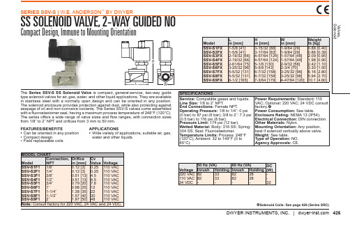
SERIES SSV-S | W.E. ANDERSON™ BY DWYER
SS SOLENOID VALVE, 2-WAY GUIDED NO
Compact Design, Immune to Mounting Orientation
H
L
W
Model SSV-S1FX SSV-S2FX SSV-S3FX SSV-S4FX SSV-S5FX SSV-S6FX SSV-S7FX SSV-S8FX SSV-S9FX
The Series SSV-S SS Solenoid Valve is compact, general-service, two-way guide type solenoid valves for air, gas, water, and other liquid applications. They are available in stainless steel with a normally open design and can be oriented in any position. The solenoid enclosure provides protection against dust, while also protecting against seepage of oil and non-corrosive coolants. The Series SSV-S valves come assembled with a fluoroelastomer seal, having a maximum process temperature of 248°F (120°C). The series offers a wide range of valve sizes and flow ranges, with connection sizes from 1/8˝ to 2˝ NPT and orifices from 3 mm to 50 mm.
欧盟阀门标准

德国(欧盟)标准1、DIN EN 1267:1999Messung des StrömungswiderstandesMit Wasser als Prüfmedium阀门—用水作为试验介质的流阻试验2、DIN EN 1349:2000Stellgeräte für die Prozessregelung 工业流程控制阀3、DIN EN 1503-1:2000Werkstoffe für Gehäuse, Obereile und DeckelTeil 1:Stähle, die in Europäischen Normen festgelegt sind阀门—壳体材料—第1篇钢4、DIN EN 1461-1999Hot dip galvanized coatings on fabricated iron and steel articles Specifications and test methods (ISO 1461:1999) English version of DIN EN ISO 14615、DIN EN 1503-2:2000Werkstoffe für Gehäuse, Obereile und DeckelTeil 2:Stähle, die Europäischen Normen nicht festgelegt sind阀门—壳体材料—第2篇 ISO钢6、DIN EN 1503-3:2000Werkstoffe für Gehäuse, Obereile und DeckelTeil 3:Gusseisen, dos in Europäischen Normen festgelegt ist阀门—壳体材料—第3篇铸铁7、DIN 1691-1985Flake graphite cast iron (grey cast iron) Properties 8、DIN 1693-1973Cast iron with nodular graphite unalloyed and low alloy grades9、DIN 3202-1-1984Bauangen von armaturen flanscharmaturen10、DIN 3202-4-1982Baulangen von armaturen armaturen mit lnnengewinde-anschiub11、DIN 3202-5-1984Baulangen von armaturen armaturen mit rohrverschraubungs- anschlub12、DIN EN 60534-2-1:1998Stellventile für die prozessregelungTeil 2-1: Durchflusskapazität Bemessungsgleichungen für Fluide nunterEinbaubedingungen工业流程控制阀—第2篇流量第1章在安装条件下对不可压缩介质流量的确定尺寸公式13、DIN 2501-1972Flanges Connecting dimensions 法兰连接尺寸。
Series PV三路常闭电磁阀试验室操作指南说明书

Series PV Solenoid Pilot ValveSpecifications - Installation and Operating InstructionsBulletin F-89-PVThe Series PV three-way normally closed electro-pneumatic solenoid pilot valve effectively regulates supply pressures for the Series SAV Angle Seat Valve. The DIN connector is reversible 180 degrees to keep electrical wiring hassle-free, while the direct mounting banjo connection simplifies valve installation. Select the proper model according to the SAV valve actuator diameter and power requirements.1. E xamine valve for transport damage.2. C ompare the technical description of valve on valve tag (on top of the coil) withyour application requirements.3. Keep dirt and debris out of valve and piping.4. DO NOT use valve or coil as a lever when installing.5. T o fit the solenoid valve onto a normally closed SAV valve, use the pilot connectionmarked “NC”; for normally open valves use the connection marked “NO”.6. W hen using water as a pilot media, remove the cap from the exhaust connectionand connect a drain line.7. A utomatic operation is standard. For manual (exhaust) operation, turn overridescrew 180° counter-clockwise. Override screw is identified by “O” and “C” engravings.8. M ake all electrical and plumbing connections in accordance with federal, state, andlocal regulations.INSTRUCTIONS FOR ELECTRICAL PLUG (see diagram below)1. Place your 18 gauge SVT or equal wire into #7, 6, 5, and 4, in that order.2. T erminate your wire into the cable fixing screws #3 and the other pole screwtermination.3. T he ground or earth termination lies in-between #3 and the other terminationscrew.4. R eassemble the connector. The valve can now be directly mounted (banjoconnection) onto the actuator.MAINTENANCEUpon final installation of the Series PV Solenoid Pilot Valve, no routine maintenance is required. A periodic check of the system calibration is recommended. The Series PV is not field serviceable and should be returned if repair is needed (field repair should not be attempted and may void warranty). Be sure to include a brief description of the problem plus any relevant application notes. Contact customer service to receive a return goods authorization number before shipping.GROUND Printed in U.S.A. 6/23FR# 443112-10 Rev.4©Copyright 2023 Dwyer Instruments, LLC When working on the Actuator/Valve assembly, disconnect the air or power supply to the actuator. Spring return actuators/valvesmay change position if power fails or is removed. Never insert any object or body part into the valve body. Severe injury may occur.。
Sporlan Valve Company 产品说明书
EB33, EMB33
127
96.9
80.8
84.2
82.6
82.4
EMB42S3
KC-3 KC-3 KC-3 MKC-2 KC-3
VALVE SERIES
W3 W6 W14
CURRENT VALVE TYPES
DISC
WITH
DIAPHRAGM
STAINLESS STEEL
INSERT
W3P1
–––
THE ABOVE PREFIXES MAY BE ADDED TO BASIC VALVE TYPE NUMBER (B25S2) TO REQUEST SPECIAL FEATURES.
Coil Size MKC-1 MKC-2 KC-3
2-398
2
Connection Type
Normally Open
Manual Lift Stem
Design Series
Port Size in 1/32"
Connections Solder
Coil Size
Connection Size
in 1/8"
0 - ODF X ODF 1 - ODF X ODM 2 - ODM X ODF
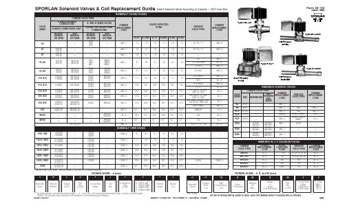
SPORLAN Solenoid Valves & Coil Replacement Guide Select Solenoid Valves According to Capacity — NOT Line Size
NORMALLY CLOSED VALVES
Form 30-122
March 1998
NORMALLY OPEN VALVES
OE9, OB9
气阀产品说明书
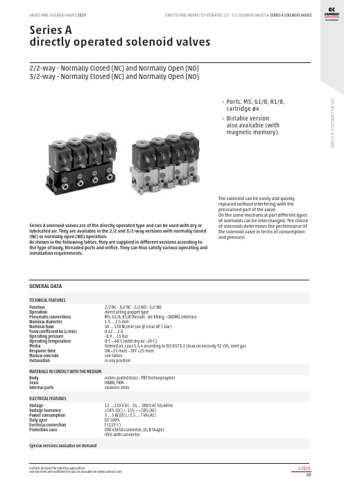
S E R I E S A S O L E N O I D V A L V E SSeries Adirectly operated solenoid valves2/2-way - Normally Closed (NC) and Normally Open (NO) 3/2-way - Normally Closed (NC) and Normally Open (NO)Series A solenoid valves are of the directly operated type and can be used with dry or lubricated air. They are available in the 2/2 and 3/2-way versions with normally closed (NC) or normally open (NO) operation.As shown in the following tables, they are supplied in different versions according to the type of body, threaded ports and orifice. They can thus satisfy various operating and installation requirements.The solenoid can be easily and quickly replaced without interfering with the pressurised part of the valve.On the same mechanical part different types of solenoids can be interchanged. The choice of solenoids determines the performance of the solenoid valve in terms of consumption and pressure.»Ports: M5, G1/8, R1/8, cartridge ø4 »Bistable version also available (with magnetic memory)GENERAL DATATECHNICAL FEATURES Function OperationPneumatic connections Nominal diameter Nominal flowFlow coefficient kv (l/min) Operating pressure Operating temperature MediaResponse time Manual override Installation2/2 NC - 3/2 NC - 2/2 NO - 3/2 NO direct acting poppet typeM5, G1/8, R1/8 threads - ø4 fitting - CNOMO interface 1.5 … 2.5 mm40 … 130 Nl/min (air @ 6 bar ΔP 1 bar) 0.62 … 2.0 -0.9 … 15 bar0°C ÷ 60°C (with dry air -20°C)filtered air, class 5.4.4 according to ISO 8573-1 (max oil viscosity 32 cSt), inert gas ON <15 msec - OFF <25 msec see tables in any positionMATERIALS IN CONTACT WITH THE MEDIUM Body SealsInternal parts nickel-plated brass - PBT technopolymer HNBR, FKM stainless steelELECTRICAL FEATURES VoltageVoltage tolerance Power consumption Duty cycleElectrical connection Protection class12 … 110 V DC - 24 … 380 V AC 50/60 Hz ±10% (DC) / -15% ÷ +10% (AC) 3 … 5 W (DC) / 3.5 … 7 VA (AC) ED 100% F (155°C)DIN 43650 connector, (A, B Shape) IP65 with connectorS E R I E S A S O L E N O I D V A L V ESCODING EXAMPLES E R I E SA S O L E N O I D V A L V E SValve function 2/2: for vacuum application connect the vacuum in “2” Valve function 3/2: for vacuum application connect the vacuum in “1” Note: for solenoid Mod. G90 (2/2 NO) contact our technical departmentTABLE FOR THE COUPLING BETWEEN SOLENOIDS AND VALVESS E R I E S A S O L E N O I D V A L V ES2/2 and 3/2-way solenoid valves Mod. A32 and Mod. A33Available in the 2/2-way version, NC or NO, as well as in the 3/2-way version, NC, NO or NO in line.In the 3/2 NC version connection 1 is on the body (fi. A), whereas in the 3/2 NO version is on the M5 thread of the tube (fig. B).Note. For the use of NO valves in line, use the coil model U771 or U7K1 or G771 or G7K1.* choose the most suitable solenoid.3/2-way solenoid valve Mod. AA31... - AA33...SymbolThe 3/2-way solenoid valves for manifold assembly are available in the NC and NO in line version, with G1/8 ports at the manifold inlet.The inlets can be with M5 threading or with a Ø 4 cartridge.The solenoid valve is supplied complete with O-ring and screws.Note. For the use of NO valves in * choose the most suitable solenoid.S E R I E S A S O L E N O I D V A LV E SThe 3/2-way NC solenoid valve, with G1/8 ports, incorporates a rapid exhaust valve.It is particularly suitable for operating small single-acting cylinders.* choose the most suitable solenoid.3/2-way solenoid valve Mod. A33They are particularly suitable for the actuation of small single-acting cylinders and the operation of pneumatic valves with very low operating pressures.The body has an outlet with a R1/8 male thread which can be screwed directly onto the component to be operated. The inlet port is M5 threaded.* choose the most suitable solenoid.S E R I E S A S O L E N O I D V A L V ESEquipped with a manual override for a steady operation, it is suitable to be mounted directly onto machine partsby two screws. The sealing is ensured by two concentric O-rings allowing the body a 360° adjustment.* choose the most suitable solenoid.3/2-way solenoid valve Mod. A53Equipped with a manual override for a steady operation, it is suitable to be mounted on Series 9 valves with an ISO interface. The interface which complies CNOMO norms is interchangeable with all ISO versions.The body only is in technopolymer.* choose the most suitable solenoid.S E R I E S A S O L E N O I D VA L V E S3/2-way solenoid valve Mod. A231 with fixed interfaceEquipped with a manual override with the possibility of a bistable actuation.* choose the most suitable solenoid.3/2-way solenoid valve Mod. A131 with swivel interfaceEquipped with a manual override with the possibility of a bistable actuation.* choose the most suitable solenoid.。