991型超低频测振仪
偷窥我军法宝:“北调991”小水线面双体水声测量船

偷窥我军法宝:“北调991”⼩⽔线⾯双体⽔声测量船
北调991(东远02)⽔声测量调查船是我国⾸艘采⽤全电⼒推进的具有⾃主知识产权的1500吨级⼩⽔线⾯双体船,由中船重⼯发起成⽴的中船东远科技发展有限公司负责研发、设计、建造的全⾯组织管理和协调,七○⼀所、七○⼆所联合设计,武昌造船⼚建造,其电⼒推进系统由七⼀⼆所集成,主要船⽤设备及特种试验装置由武汉船⽤机械有限责任公司、河南柴油机集团有限责任公司、⼭西汾西重⼯有限责任公司、重庆华渝电⽓仪表总⼚、北京长城⽆线电⼚等单位承制,是⼀艘由中船重⼯研制的全部集团化产品。
该船具有宽⼴的甲板⾯积和优良的耐波性、操纵性。
在设计中,主要解决了浅吃⽔⼩⽔线⾯双体船线型优化、⼤开⼝双体船体结构强度设计、综合电⼒推进系统集成、⾼精度长⾏程特种试验装置研制、全船浮态调整辅助决策系统等关键技术。
在建造过程中,采⽤全三维⽣产设计,确保了设计正确性、重量重⼼控制和制造精度;编制了典型潜体装焊⼯艺、⼤型⽔井装焊⼯艺、全船重量控制实施细则等11项新⼯艺⽂件,解决了潜体薄板焊接、重量控制、振动噪声等关键建造技术。
经过海上航⾏试验检验,该船性能及各项技术指标完全达到了设计要求。
TS8991 OTA性能测试系统

R&S®EMC32/R&S®AMS32 测量软件包含开源软件包。有关各自许可的副本包含在 “R&S®EMC32 和 R&S®AMS32 测量软件开源确认”中。详情请参阅此网页的下载/ 软件部分。
Over-the-Air (OTA) 测量是无线设备性能评估和认证的重要部分。 科电贸易 TS8991 OTA 性能测试系统可测量发射功率和接收机灵敏度性能指标, 例如 CTIA 和 3GPP 中指定的 EIRP、TRP、EIS、TRS/TIS、共存性、灵敏度劣化 以及中间信道灵敏度。罗德与施瓦茨分解方法支持 MIMO OTA 测试。
TS8991 OTA 性能测试系统
科电贸易 TS8991 OTA 性能测试系统适用于天线、蜂窝及非蜂窝测试的交钥匙空 中传输 (OTA) 解决方案
科电贸易 TS8991 OTA 性能测试系统的主要特点 根据 CTIA、3GPP、Wi-Fi Alliance、CWG、PTCRB 标准和测试用例测量空中
科电贸易 TS8991 OTA 性能测试系统的特点和优势 1. 交钥匙测试解决方案 R&S®TS8991 OTA 性能测试系统可根据客户具体要求进行灵活配置。罗德与施瓦 茨提供多种交钥匙测试解决方案,包括: R&S®TS8991 系统机架(含测试仪器) R&S®AMS32 系统软件 第三方附件,例如头部和手部模型、校准天线、纹波测试套件等 无线性能试验室 (WPTC) 定位系统 系统工程 全球项目管理 系统培训 现场安装 系统校准 最终验收测试 系统维护
支持的技术 4. 卫星导航 A-GPS A-Glห้องสมุดไป่ตู้nass 5. 蜂窝 LTE-FDD/TD-LTE LTE-U WCDMA / HSPA / HSPA+ TD-SCDMA CDMA 1x、1xRTT、EvDO GSM/GPRS/EDGE 6. 无线连接 WLAN (802.11a/b/g/n) Bluetooth®
AHAI6256型振动分析仪使用说明书

2 主要特点
大于 110 dB 的超大级线性范围,1 档大量程,无需切换; 多分析功能、记录、录音同步启动; 彩屏显示器,分辨率 240×320,阳光下可读,显示内容 丰富,亮度可自动调节; 具有电池和外接电源自动切换功能; 低功耗,续航时间长; RS232/485 可切换通信接口; 内嵌蓝牙模块,实现无线打印和手机 app 通信(选配); 大容量存贮:最大支持 32 GB SD 卡(选配)。
手传振动测量 Vwhi、VwheqT、Vwheq4h、Vwheq8h
Max、Min、Leq,T、5 个 Ln(n 可以从 1 到 99 低频 1/3 OCT 分析 之间设定)、30 个中心频率点、AP、SD、5
振动 1/3 OCT 分析
个合成频率计权(wz、wx、wm、wk、wu) Max、Min、Leq,T、30 个中心频率点、acc、 vel、disp
1
AHAI6256 型振动分析仪使用说明书
3 主要技术性能
1) 符合标准: —— GB/T 23716—2009 人体对振动的响应 测量仪器 (ISO 8041:2005 , IDT); —— GB/T 3241—2010 电声学 倍频程和分数倍频程滤波器 (IEC 61260:1995, MOD); —— GB/T 10071—1988 城市区域环境振动测量方法; —— GB/T 13441.1—2007 机械振动与冲击 人体暴露于全身振 动的评价 第 1 部分:一般要求 (ISO 2631-1:1997 , IDT); —— GB/T 13441.2—2008 机械振动与冲击 人体暴露于全身振 动的评价 第 2 部分:建筑物内的振动(1 Hz~80 Hz) (ISO 2631-2:2003, IDT); —— GB/T 14790.1—2009 机械振动 人体暴露于手传振动的测 量与评价 第 1 部分:一要求 (ISO 5349-1:2001, IDT); —— GB/T 14790.2—2014 机械振动 人体暴露于手传振动的测量 与评价 第 1 部分:工作场所测量实用指南(ISO 5349-1:2001, IDT); —— GB/T 50355-2005 住宅建筑室内振动限值及其测量方法标 准; —— JGJ/T 170-2009 城市轨道交通引起建筑物振动与二次辐射 噪声限值及其测量方法标准; —— 其他相关标准等;
ga991 安全评估

ga991 安全评估
安全评估是指对某一系统、设备、软件或网络等进行全面评估和检验,以确定其安全性和脆弱性,找出潜在的安全隐患,并提出相应的改进建议。
对于GA991来说,安全评估可以包括以下方面:
1. 系统安全性评估:评估GA991系统的防入侵、认证与授权、访问控制、数据加密等安全机制的有效性和完整性。
2. 网络安全评估:评估GA991网络的防火墙设置、数据传输
加密、入侵检测和防范等网络安全机制的可靠性和有效性。
3. 物理安全评估:评估GA991设备的物理安全措施,包括防盗、防损坏、防灾害等安全措施的实施情况和效果。
4. 数据安全评估:评估GA991系统中处理、存储和传输的数
据的安全性,包括数据加密、备份和恢复机制的可靠性。
5. 社会工程学评估:评估GA991系统中对社会工程学攻击的
抵御能力,包括对假冒、诈骗、网络钓鱼等攻击手段的防范和检测能力。
6. 安全策略和政策评估:评估GA991系统中的安全策略和政
策的合理性和有效性,是否能够满足实际的安全需求。
综合评估结果,可以找出GA991系统存在的安全隐患和脆弱
性,并提出相应的安全改进措施,以提高系统的安全性和稳定性。
CS9911BI 程控耐压测试仪

CS9911BI 程控耐压测试仪简介CS9911BI 程控耐压测试仪是一种广泛应用于电气设备、电线电缆、灯具、电源、电机、变压器、开关等领域测试设备。
它可以在设备的绝缘材料之间施加高电压,以测试设备是否符合电气安全标准。
CS9911BI 程控耐压测试仪采用先进的数字技术和外部晶体管(FET)导通控制技术,充分发挥了机器的稳定性、准确性和可靠性。
技术指标入口•电源:AC 220V±10%,50Hz±5%•额定功率:400VA输出•最高电压:AC 0-30kV(可选),DC 0-40kV(可选)•最高电流:AC 0-10mA(可选),DC 0-5mA(可选)•频率:50Hz/60Hz 自动识别•分辨率:0.01kV/0.01mA其他规格•单机尺寸:362mm415mm224mm•单机重量:19kg•工作环境:温度 0℃-40℃,相对湿度 0-80%•存储环境:温度 -20℃-60℃,相对湿度 0-80%特点具有多种保护功能CS9911BI 程控耐压测试仪提供了多种保护功能,包括过流保护、过压保护、漏电保护、过载保护、短路保护等等。
可编程性强CS9911BI 程控耐压测试仪可以存储和输出多种测试程序,满足不同的测试需求。
显示屏幕大CS9911BI 程控耐压测试仪配备了高清晰的液晶屏幕,能够显示电压、电流、时间、波形等多种参数,方便操作人员观察测试结果。
稳定性强CS9911BI 程控耐压测试仪采用外部FET导通控制技术,具有更高的可靠性和稳定性。
应用领域CS9911BI 程控耐压测试仪广泛应用于以下领域:•电气设备•电线电缆•灯具•电源•电机•变压器•开关优势CS9911BI 程控耐压测试仪具有以下优势:1.VC控制,高精度数字技术2.具备高压、低漏电保护功能3.外部FET导通控制技术,绿色无污染4.双路绝缘测试,适用于电气设备的测试5.智能本地管理6.可编程性强,即插即用缺点CS9911BI 程控耐压测试仪的价格相对较高,适用于专业的电气测试领域,不适用于个人家庭测试。
iSV2101 测振仪 注意事项及使用指南说明书

iSV2101测振仪2019.4.23注意事项1、第一次使用仪器前,请仔细阅读该说明书。
2、其它因使用不当造成的损坏不在保修范围之内。
3、锂电池应每3个月进行一次充放电,电池保修3个月。
4、仪器维修时请附带保修单。
更改记录及版本说明版本说明V1.0iSV2101测振仪第一版目录1、概述 (1)2、主要技术性能 (1)3、结构及功能 (2)3.1按键 (5)3.2关键零部件 (5)4、使用方法 (5)4.1使用前的准备 (5)4.2外接电源 (6)4.3电池检查及更换电池 (6)5、操作说明 (6)5.1开关机 (6)5.2界面 (6)附录F:名词术语 (8)1、概述iSV2101测振仪是一款测量加速度、速度、位移的仪器,它能分别显示这三种数据的有效值rms、峰值peak、峰峰值p-p。
仪器符合JJG676-2000《工作测振仪》检定规程,适用于工厂企业、环境保护、劳动卫生、教学、科研等领域。
2、主要技术性能(1)传感器:AWA84107,灵敏度约:2.5pC/m·s-2;(2)测量范围(有效值)(以1pC/m·s-2为参考):加速度:0.06m/s2~2000m/s2速度:0.6mm/s~20000mm/s位移:0.05mm~100mm(3)频率范围:加速度:10Hz~8kHz速度:10Hz~4kHz位移:20Hz~200Hz(4)主要测量指标:同时测量a、v、s的有效值、峰值或峰峰值(5)显示:128×64点阵OLED(6)硬件接口:USB(7)电源:锂电池:充满电后,可连续工作20小时以上外接电源:5V1A USB接口电源(8)外形尺寸:l×b×h(mm):170×75×24(mm)。
(9)质量:182g。
(10)使用条件:气温:-10℃~+50℃相对湿度:25%~90%气压:65kPa~108kPa13、结构及功能仪器的外形见图1和图2,它由振动传感器和主机组成。
绝缘耐压测试仪 说明CS991

险!正在高压测试,非工作人员请勿靠近” 。 1.3.2 输入电源
耐压测试仪必须有良好的接地。本耐压测试仪的后面板上有一接地端,请将此接地端子与大地 接触良好。本耐压测试仪必须有单独的开关,把此开关安装于特别明显的位置并标明其功用。一旦 有紧急事故发生,可以立即关闭电源,以便处理故障。 本耐压测试仪输入电源为交流电源。电源范围为交流(AC)220V±10%,电源频率为 50Hz,在 该电源范围内如电源不稳定则有可能造成本耐压测试仪异常动作或损坏测试仪内部元件。
3.1.2 自动降压
用户可根据时间设置电压下降的速度,比如,额定测试电压为 1000V,要测试仪每秒下降 50V, 那么可把电压上升时间设置为 20s,如果要测试仪每秒下降 200V,那么可把电压上升时间设置为 5s。 在电压下降的过程中,如果测试电流大于设置电流的上限,仪器将自动切断输出电压,发出声光提 示,并且在显示屏上保留显示当前的电压值和电流值。
第3页
2007 年 10 月 Ver:1.2
CS99I 系列测试仪使用手册
长盛仪器
(2)当作绝缘测试或直流测试时,被测体在测试完以后有可能有高压存在,此电压在电源开关 关闭以后,需要一段时间放电才可能放电完全。因此刚测试完请不要立即触摸任何可能造成触电的 地方。
8. 更换待测物
当一个待测物已被测试完毕,更换另一个待测物时,请务必确认: 测试仪处于“复位”状态。 测试灯不闪烁。 液晶显示器电压显示数字不在跳动。
特别注意:更换待测物时,请不要用手触摸高压探头! ! ! 9. 启或关闭电源开关
一旦电源开关被切断时,如再度开启时,则需等几秒之后,千万不要把电源开关连续做开与关 的动作,以免产生错误的动作损坏测试仪。尤其是当正有高压输出的状态下连续做电源的开与关是 非常危险的。
F991M标准

2
4.1.1 ASTM designation and year of issue. 4.1.2 Type (See Section 3). 4.1.3 Optional nonstandard materials. 5. Materials and Manufacture 5.1 Materials: 5.1.1 Boss—ABS Grade A or B, plate or bar. 5.1.2 Plug—Specification B 164 rod or bar. 5.1.3 Other materials may be substituted to suit hull construction as approved by regulatory bodies. 5.2 Manufacture: 5.2.1 Plugs and bosses shall be machined. 5.2.2 Threads shall be in accordance with ANSI B2.1. 6. Dimensions and Tolerances 6.1 Dimensions shall be as indicated in Fig. 1 and Fig. 2. 6.2 Tolerance shall be 61.5 mm. 6.3 Mass shall be as follows:
1 This specification is under the jurisdiction of ASTM Committee F-25 on Shipbuilding and is the direct responsibility of Subcommittee F25.01 on Structures. Current edition approved Feb. 15, 1995. Published April 1995. Originally published as F 991 – 86. Last previous edition F 991 – 86. 2 Annual Book of ASTM Standards, Vol 02.04. 3 Available from American Bureau of Shipping, 2 World Trade Center, 106th Floor, New York, NY 10048. 4 Available from American National Standards Institute, 11 W. 42nd St., 13th Floor, New York, NY 10036.
ASTM A991-A991M - 10
Designation:A991/A991M−10Standard Test Method forConducting Temperature Uniformity Surveys of Furnaces Used to Heat Treat Steel Products1This standard is issued under thefixed designation A991/A991M;the number immediately following the designation indicates the year of original adoption or,in the case of revision,the year of last revision.A number in parentheses indicates the year of last reapproval.A superscript epsilon(´)indicates an editorial change since the last revision or reapproval.1.Scope*1.1This test method covers the procedures used to conducta temperature uniformity survey on a furnace used to heat treat steel products.This method is used to determine the capability of the furnace to meet the permissible temperature variation specified in the applicable product specification,or as agreed to by the purchaser and supplier of heat treat services.Survey documentation requirements,and the procedure used to subse-quently establish the furnace working zone,are defined in this test method.1.2This test method covers heat treat furnaces in any of the following categories:1.2.1Continuous or semi-continuous conveyance furnaces, 1.2.2Batch furnaces,and1.2.3Salt or liquid baths andfluidized beds.1.3This test method only applies when specified in the product specification or the purchase order.1.4Controlling a heat treatment of steel products using thermocouples attached to the extremities of each load is an alternative to performing a furnace survey.1.5By mutual agreement between the purchaser and the supplier of heat treat services,more stringent and/or additional requirements may be specified.The acceptance of any such additional requirements shall be dependent on negotiations with the supplier and must be included in the order as agreed upon by the purchaser and supplier.1.6The values stated in either SI units or inch-pound units are to be regarded separately as standard.The values stated in each system may not be exact equivalents;therefore,each system shall be used independently of the bining values from the two systems may result in non-conformance with the standard.1.7This standard does not purport to address all of the safety concerns,if any,associated with its use.It is the responsibility of the user of this standard to establish appro-priate safety and health practices and determine the applica-bility of regulatory limitations prior to use.2.Referenced Documents2.1ASTM Standards:2E207Test Method for Thermal EMF Test of Single Thermo-element Materials by Comparison with a Reference Ther-moelement of Similar EMF-Temperature PropertiesE220Test Method for Calibration of Thermocouples By Comparison TechniquesE230Specification and Temperature-Electromotive Force (EMF)Tables for Standardized ThermocouplesE608/E608M Specification for Mineral-Insulated,Metal-Sheathed Base Metal Thermocouples2.2SAE Standard:3AMS2750Pyrometry3.Terminology3.1Definitions of Terms Specific to This Standard:3.1.1batch furnace,n—heating device in which material may be stationary or oscillating during the processing cycle.3.1.2continuous conveyance furnace,n—heating device through which material is moved intentionally at a constant rate during the processing cycle.3.1.3extremities,n—as referring to furnace working zone; outer boundaries in all three dimensions(length,width,and height)of the material being processed.3.1.4operating range,n—expected range of temperature over which a furnace will be controlled to heat treat steel products.3.1.5primary survey,n—initial evaluation of the furnace,or an evaluation triggered by the initiation of a major furnace modification.1This test method is under the jurisdiction of ASTM Committee A01on Steel,Stainless Steel and Related Alloys and is the direct responsibility of Subcommittee A01.13on Mechanical and Chemical Testing and Processing Methods of Steel Products and Processes.Current edition approved April1,2010.Published April2010.Originally approved st previous edition approved in2008as A991/A991M–08. DOI:10.1520/A0991_A0991M-10.2For referenced ASTM standards,visit the ASTM website,,or contact ASTM Customer Service at service@.For Annual Book of ASTM Standards volume information,refer to the standard’s Document Summary page on the ASTM website.3Available from Society of Automotive Engineers(SAE),400Commonwealth Dr.,Warrendale,PA15096-0001,.*A Summary of Changes section appears at the end of this standard Copyright©ASTM International,100Barr Harbor Drive,PO Box C700,West Conshohocken,PA19428-2959.United States3.1.6secondary survey,n—evaluation of the furnace trig-gered by the expiration of a time requirement.3.1.7semi-continuous conveyance furnace,n—heating de-vice through which material is moved intentionally with a predetermined start-stop-start pattern during the processing cycle.3.1.8working zone,n—maximum volume and location in the furnace that meet the permissible temperature variation.4.Significance and Use4.1Furnaces for heat treatment of steel products are used in many industries,in many ways.Regardless of heat treat furnace type,or processing cycle,it may be necessary for users to know the temperature uniformity in the furnace and whether the material is processed in a zone within the furnace that is capable of meeting the applicable permissible temperature variation requirements.4.2The procedures in this test method may be used by those using,manufacturing,and providing calibration service for, heat treat furnaces used to process steel products.5.Furnace Survey Equipment5.1Thermocouples:5.1.1Metal sheathed thermocouples shall be in accordance with Specification E608/E608M.5.1.2The use of extension wires is permitted when com-pensated connectors,plugs,jacks,and terminal strips are used.5.1.3Thermocouples made from spool wire shall meet the requirements of AMS2750.5.1.4The use of spliced extension wire is prohibited.5.1.5Thermocouples may be reused if the requirements of AMS2750(except Paragraphs3.1.1.10and3.1.1.11of Rev.D) are met.5.2Calibration:5.2.1All reference,primary,secondary,test and working equipment,instrumentation and sensors used in conjunction with this test method shall meet the requirements of calibration defined by Test Methods E207and E220.5.2.2Temperature measuring devices shall be calibrated within three months prior to use.5.2.3Calibration shall be traceable to the National Institute of Standards Technology standards,or equivalent national standards.Calibration to such national standards shall be done at least once every two years.5.2.4Calibration shall be within the temperature range to be used in the survey and at intervals not greater than200°F [100°C]for primary and secondary standards.5.2.5Correction factors,limits of error,and deviations shall be in accordance with Specification E230.6.Requirements6.1Uniformity Survey Test Conditions:6.1.1The furnace to be surveyed shall be capable of being tested at set point temperature(s)typical for the normal operating range.6.1.1.1If the operating range does not exceed a spread of 300°F[150°C],the midpoint temperature shall be selected for the survey.6.1.1.2If the operating range exceeds a spread of300°F [150°C],survey at the minimum and maximum set point temperature for the normal operating range,except that the maximum temperature need not be higher than2000°F [1100°C].6.1.2Either typical or maximum production size and weight furnace loads shall be utilized during the e of representative material to simulate product during survey is permitted.6.1.3The furnace atmosphere and operating conditions shall be representative of those used in production.6.2Frequency of Uniformity Surveys:6.2.1Primary Surveys:6.2.1.1A primary survey shall have been performed within twelve months prior to,or run concurrently with,thefirst production heat treatment to which this test method applies.6.2.1.2A primary survey shall have been conducted when a major furnace modification is completed.A major furnace modification includes,but is not limited to,the installation of the following:a different burner type,a new heating element design,a different type of insulation system,and,a different type of temperature controlling device.6.2.1.3Replacement of worn parts with similar parts or patching of insulation that does not change the furnace characteristics does not constitute a major furnace modifica-tion.6.2.1.4The survey shall be conducted within twelve months prior to,or run concurrently with,thefirst production heat treatment performed after the modification.6.2.2Secondary Surveys:6.2.2.1To maintain conformance with this test method,a secondary survey shall be conducted within twelve months after the primary survey.6.2.2.2Secondary surveys shall be conducted at a typical furnace set point temperature within the normal operating range.All other conditions described in6.1shall apply.7.Procedure7.1Survey measuring equipment shall meet the require-ments of Section5.7.2Test conditions and test frequency shall be as defined in6.1and6.2,respectively.7.3Place thermocouples to monitor time and temperature profiles in the furnace to evaluate the uniformity of the intended working zone.Place them at the outer extremities,the center of the proposed working zone,and in areas of suspected variability in the proposed working zone.Attach survey test sensors to,or set them in the load.7.4For proposed working zones less than12in.[300mm] in height,it is acceptable to monitor the center height location, it is not necessary to monitor both the top and bottom of the heating chamber.For proposed working zones greater than,or equal to,12in.[300mm]in height,both top and bottom extremities must be monitored.7.5Continuous Conveyance and Semi-Continuous Convey-anceFurnaces:7.5.1Convey test sensors through the furnace.The rate of conveyance shall be representative of normal operating condi-tions.7.5.2The frequency of temperature recordings shall be capable of detecting variations from the test temperature range during the entire conveyance through the furnace.7.5.3Several conveyances with the test sensors attached to the steel product,under the same conditions,may be made to ensure that any recurrent temperature profiles are determined at all test locations throughout the furnace.7.5.4Alternative surveying techniques are described in7.7.7.6Batch and Batch Liquid Media Furnaces:7.6.1Take readings starting when the control instrument rises to within200°F[100°C]of the set point temperature and continue throughout the hold cycle at the set point temperature.7.6.2Take readings at a minimum frequency of1/10the normal hold time.7.6.3Take the readings frequently enough to detect varia-tions from the test temperature range and to determine the extremes of the recurrent temperature profile,if any.7.6.4Alternative surveying techniques are described in7.7.7.7Alternative Surveying Techniques—When agreed to by the purchaser and the supplier of heat treat services,alternative surveying techniques may be used to characterize the tempera-ture uniformity of the furnace and subsequently define the size and location of the working zone.Examples of these surveying techniques are listed below.7.7.1Statistical Sampling:7.7.1.1When it is impossible or impractical to perform the tests outlined in7.5and7.6,it is permissible to substitute an analysis of the resultant mechanical properties of the steel products heat treated in the subject furnace to validate tem-perature uniformity.Details of this procedure shall be as agreed to between purchaser and supplier.7.7.2Sequential Load Sensors:7.7.2.1This procedure may be used as an alternative to those described in7.5and7.6.It provides validation of temperature uniformity by a series of tests rather than a single test.In each test,determine the temperature variation pattern at one or more of the test locations.7.7.2.2The frequency of test shall be six months.7.7.2.3The temperature shall be within the normal operat-ing range,with the narrowest permissible variation for the material applied to the survey.7.7.2.4Run the furnace with a load similar to that used in a normal production cycle.7.7.2.5Load or test sensors shall be arranged in,or in contact with,the test load.7.7.2.6Control setting(s)shall be identical to those used in normal production.7.7.2.7Take readings starting when the control instruments rises to within200°F[100°C]of the set point temperature and continued throughout the hold cycle at the set point tempera-ture.7.7.2.8Record the temperature of all load test and working sensors frequently enough to detect when the specified oper-ating range is exceeded,and at leastfive cycles of any recurrent pattern have been observed.7.7.2.9If no recurrent temperature profile is detected,take readings at intervals offive minutes or less,for at least30min after thermal equilibrium is reached.8.Documentation of Survey Results8.1Organizations performing surveys in accordance with this test method shall keep pertinent documentation of the conditions and procedures used in the completion of the survey onfile for a minimum offive years.8.2Pertinent documentation shall include,but not be lim-ited to,the following:8.2.1Specific identification of furnace surveyed,8.2.2Date of the uniformity survey,8.2.3Identification of the heat treat procedure,8.2.3.1Set point temperatures,8.2.3.2Type of atmosphere,8.2.3.3Conveyance speed(when applicable),8.2.4Size and weight of steel product loaded in furnace at time of survey,8.2.5Item identification numbers(lot,heat serial,etc.), 8.2.6Time and temperature data,including original tem-perature charts or original manually recorded data,8.2.7Dimensions and location of the working zone(s), 8.2.8Number and location of the survey thermocouples, 8.2.9Largest observed temperature variation from the set points during the hold cycle,8.2.10The time interval of the test,including the total elapsed time.Starting time and chart speed shall be marked on the original temperature charts,8.2.11All pertinent equipment calibration information, 8.2.12Deviations from the test method including,but not limited to,thermocouple failure,malfunction,or disconnec-tion.8.2.13Name of personnel conducting the survey,and8.3All data may be electronically recorded.9.Interpretation of Results and Establishment of the Working Zone9.1The results of the primary survey describe the tempera-ture uniformity of a furnace under a specific set of operating conditions.Results of the application of this test method shall be expressed as a variation from a temperature set point.9.2Establishment of the furnace working zone is made by comparing the temperature variation required by the product specification,or agreed to by purchaser and supplier of heat treat services,with the variation from the temperature set point as determined by this uniformity survey.9.3The working zone may either be the entire heating volume,or it may only be some portion of the heating volume of the furnace.The working zone may be comprised of one or more heating zones in the furnace.10.Heat Treatment in the Working Zone10.1When invoked by the product specification,or agreed to by purchaser and supplier of heat treat services,steel products shall be heat treated,as specified,only in the workingzone.11.Precision and Bias11.1Precision—It is not possible to specify the precision of the procedure in this test method for measuring furnace uniformity because precision can vary with the furnace being surveyed.11.2Bias—No information can be presented on the bias of the procedure in this test method for measuring furnace uniformity because bias can vary with the furnace being surveyed.12.Keywords12.1furnace survey;temperature;uniformity;working zoneSUMMARY OF CHANGESCommittee A01has identified the location of selected changes to this standard since the last issue (A991/A991M–08)that may impact the use of this standard.(Approved April1,2010.)(1)Added new Section11.ASTM International takes no position respecting the validity of any patent rights asserted in connection with any item mentioned in this ers of this standard are expressly advised that determination of the validity of any such patent rights,and the riskof infringement of such rights,are entirely their own responsibility.This standard is subject to revision at any time by the responsible technical committee and must be reviewed everyfive years and if not revised,either reapproved or withdrawn.Your comments are invited either for revision of this standard or for additional standardsand should be addressed to ASTM International Headquarters.Your comments will receive careful consideration at a meeting of theresponsible technical committee,which you may attend.If you feel that your comments have not received a fair hearing you shouldmake your views known to the ASTM Committee on Standards,at the address shown below.This standard is copyrighted by ASTM International,100Barr Harbor Drive,PO Box C700,West Conshohocken,PA19428-2959, United States.Individual reprints(single or multiple copies)of this standard may be obtained by contacting ASTM at the aboveaddress or at610-832-9585(phone),610-832-9555(fax),or service@(e-mail);or through the ASTM website().Permission rights to photocopy the standard may also be secured from the ASTM website(/COPYRIGHT/).。
991b拾振器 工作原理

991b拾振器工作原理
991b拾振器工作原理是通过利用电磁学原理,将机械振动转化为电信号。
具体原理如下:
1. 电磁感应:991b拾振器内部包括一个线圈和一个磁铁。
当磁铁与拾音体产生机械振动时,线圈内的磁场也会随之变化。
2. 磁场变化:振动将磁铁靠近和远离线圈,使得线圈内的磁场变化频率与振动频率相同。
3. 感应电流:根据电磁感应定律,当磁场发生变化时,线圈内会产生感应电流。
振动频率与感应电流频率一致。
4. 输出电信号:感应电流经过放大和滤波处理后,就可以作为振动的电信号输出。
总结起来,991b拾振器的工作原理是利用磁感应现象将机械振动转化为感应电流,再通过电路处理得到输出的电信号。
安捷伦N9912A实验仪器简单使用手册
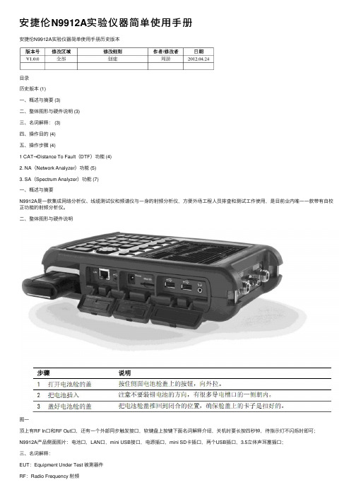
安捷伦N9912A实验仪器简单使⽤⼿册安捷伦N9912A实验仪器简单使⽤⼿册历史版本⽬录历史版本 (1)⼀、概述与摘要 (3)⼆、整体图形与硬件说明 (3)三、名词解释: (3)四、操作⽬的 (4)五、操作步骤 (4)1 CAT→Distance To Fault(DTF)功能 (4)2. NA(Network Analyzer)功能 (5)3. SA(Spectrum Analyzer)功能 (7)⼀、概述与摘要N9912A是⼀款集成⽹络分析仪、线缆测试仪和频谱仪与⼀⾝的射频分析仪,⽅便外场⼯程⼈员排查和测试⼯作使⽤,是⽬前业内唯⼀⼀款带有⾃校正功能的射频分析仪。
⼆、整体图形与硬件说明图⼀顶上有RF In⼝和RF Out⼝,还有⼀个外部同步触发接⼝,软键盘上按键下⾯名词解释介绍,关机时要长按四秒钟,待指⽰灯不闪烁时即可;N9912A产品侧⾯图⽚:电池⼝,LAN⼝,mini USB接⼝,电源插⼝,mini SD卡插⼝,两个USB插⼝,3.5⽴体声⽿塞插⼝;三、名词解释:EUT:Equipment Under Test 被测器件RF:Radio Frequency 射频dBm:分贝毫⽡,在射频领域中使⽤此单位作为功率的单位,其与功率转换的公式:y dBm=10lg(x/1mw)Mode:模式(按此键可选择测试的功能)有CAT线缆测试功能,NA⽮量分析仪功能,SA 频谱分析仪功能,Power Meter功率测试功能;Freq/Dist:频率/距离;Sacle/Amptd:⽐例/幅度(当屏幕⽆法显⽰你所需要的范围时,你可以按Sacle⾃动调整你的显⽰宽度;当EUT的最⼤值⼤于你所设定的幅值,你需要调⼤你的幅值(参考电平),RF In最⼤不超过27dBm,RF out 最⼤不超过23dBm)Maker:标记(当你需要知道最⼤值为多少时,可使⽤mark功能,读出Peak点,即最⼤值)Mkr→/Tools:Maker⼯具,可以寻找下⼀个Peak点;Measure:选择测试的功能Meas Setup:测试功能的设置System:系统设置Preset:复位BW:Bandwidth带宽Cal:校准Limit:限值Sweet:扫描Trace:轨迹,在频谱仪功能中常⽤到Save/Recall:保存/调⽤⽂件Run/Hold:运⾏/静⽌四、操作⽬的1.主要是为了现场勘查线缆断路问题,查找出有问题的线缆,并且确认其距离;2.可以测试天线的驻波⽐,调试RF电路的匹配值;3.可以测试EUT的频谱功能和最⼤发射功率;五、操作步骤1CAT→Distance To Fault(DTF)功能:测试线缆的开路点,通过对应线缆的回波损耗(S11)即可以判断其开路点的距离;1.1使⽤CA T功能需要接RF OUT⼝,此时先不接DUT;1.2按Preset→Preset键复位⼀下仪器;1.3进⼊CA T→Measure→Distance To Fault(dB)→Freq/Dist→设定StartDistance(输⼊数字和单位)和Stop Distance;1.4快速校准:Cal 5→Start Cal→QuickCal等待100%完成之后→Skip Load→Finish,此时会⾃动跳回DTF界⾯;1.5连接EUT(线缆),点击Mkr→/Tools点击Peak,找到最⼤值(回波损耗最⼤值),就是开路的那个位置,在右上⾓会显⽰M1的值(包括开路位置和回波损耗值);如果需要对另外⼀个点标记,按Marker→Marker Table(ON),显⽰标记列表,此时你可以显⽰多个Marker点,按Marker对应的长⽅形框即表⽰选中Marker点的序号,之后按Normal(可输⼊你想要的位置的值)键即可以显⽰出来对应的图标,点击Mkr→/Tools点击Peak,找到最⼤值,就是开路的那个位置;如图⼆:图⼆2.NA(Network Analyzer)功能:测试天线参数,如S11(回波损耗)参数、VSWR(驻波系数)、Smith圆图;2.1.使⽤NA功能需要接RF OUT⼝,此时先不接DUT;2.2.进⼊Mode→NA→Measure→Format【Log Mag】,通常我们使⽤VSWR和Smith两个功能;2.3.选中VSWR:测试天线的驻波⽐≥1,越靠近1越好,⼀般⼯业上在1.5左右;如天线的频段在470~510MHz使⽤,你可以如下操作:Freq/Dist→Start Frequency:460MHz →Stop Frequency:520MHz;也可以Freq/Dist→Center:485MHz→Freq Span:60MHz,两步的操作效果是⼀样的,做完频率设定校准,所有关系到天线线缆的测试操作都需要做校准,连续测试的话只要做⼀次校准即可;2.4.快速校准:按Cal→Start Cal→QuickCal等待100%完成之后→Skip Load→Finish,此时会⾃动跳回NA测试界⾯,校准完成之后可以看到所有点会集中在Smith圆图上的⽆穷点处;2.5.连接好天线,VSWR的数值会直接在界⾯上显⽰,此时可以选择Marker功能寻找对应频率点的值;按Marker→Normal→470.5MHz标记会⾃动跳到你所设置的频率点,可以多设Marker点,与CAT操作⼀致;天线驻波的测试,位置最低处驻波系数最好,如图三:图三3.SA(Spectrum Analyzer)功能:主要测试DUT的功率和杂散指标,;3.1.使⽤SA功能需要接RF IN⼝(右边⼝),接好连接好仪器和EUT(最好加个衰减器,防⽌功率过⼤超出量程范围打坏仪器);3.2.设置中⼼频率:进⼊Mode→NA→Freq/Dist→Center,设定中⼼频率475.75MHz;设定展频宽度:Freq Span,如5MHz(即473.25~478.25MHz),展频越⼤看到的频率范围越宽;3.3.设置参考电平:设定的参考电平⼀定要⽐DUT所发射的电平功率要⼤,防⽌超过仪器的动态范围,损坏仪器;按Scale/Ampted→Ref Level设置参考电平,如我们的产品发射指标18dBm,需要设置参考电平20dBm以上;3.4.连接DUT测试其频谱,此时频谱跳动速度快,需要锁住频谱轨迹;按Trace 6→State[MaxHold],就会锁住所有的频谱值,需要清除时按State[MaxHold]⾥的Clr/Wr键即可;也可以选择Trace的第⼆个轨迹,锁定最⼤保持,选择Trace 6→即会出现第⼆条轨迹,仪器会锁住所⾛过的最⼤轨迹,之后按Marker→Peak即可以找到中⼼频道的功率值(这样测试功率值会⽐实际的值⼩),如果Mark点不MaxHold 线上,可以选择Marker→More→Marker Trace选择对应的轨迹线。
941B超低频测振仪使用说明方案

目录一.概述二.主要技术指标三.原理四.使用方法五.仪器的成套性附:常见故障排除郑先生嘉兴市振恒电子技术有限责任公司邮箱(Mail):地址(Add):嘉兴市南湖区亚太路778号中国科学院园区8号楼1101邮编(Zip):314006941B型超低频测振仪一.概述941B型超低频测振仪是一种用于超低频或低频振动测量的多功能仪器,目前已被公司、高等院校、科研院所等机构广泛应用于多种场合的振动测量和监测,以优异的性能获得了用户的认可。
1.用途1)地面和各种结构物的脉动测量及振动监测。
2)一般工程结构如桥梁、楼房、码头、大坝、海洋平台等的脉动测量和各种振动试验中的振动测量及监测。
3)诸如水轮发电机组等大型旋转设备的振动测量。
4)隔振平台等的微弱振动测量。
5)诸如悬索桥等高柔结构的超低频大幅值测量。
6)其他低频超低频振动测量。
2.特点1)一机多能:通过拾振器的微型拨动开关,可直接测量加速度或速度,与放大器配接后,可测量位移。
2)使用方便:拾振器无需电源供电,无需调零。
3)性能优异:由于使用了无源伺服反馈技术,能够实现超低频(低至0.17Hz)大位移(600mm)振动测量。
4)宽频带、高分辨率、大动态范围、抗冲击性能好、适合运输,可直接与各种数5)据采集系统配接。
振动测量系统一般包括传感器、放大器和数据采集仪三部分。
941B型振动传感器可与941型放大器,G01型数据采集仪(USB接口)构成一套完整的振动测试系统,完成各种振动测量和分析任务。
放大器具有放大、积分、高陡度滤波和阻抗变换的功能,G01型数据采集分析系统可完成数据采集和分析功能。
用户可根据需要,选取拾振器上微型拨动开关及放大器上参数选择开关相应的档位,可提供测点的加速度、速度或位移参量,并可提供不同频带和不同滤波陡度。
如用户对传感器、放大器、数据采集仪有特殊要求,可提前通知我们,我们可按客户要求特殊制作。
二.主要技术指标12 放大倍数K:参数选择开关置于1时,K=10~5000;参数选择开关置于2时,K=1~500;参数选择开关置于3时,K=5~2000;K I1=20; 参数选择开关置于4时,K=1~500;K I2=4; 其中K I1及K I2为积分增益34输出负荷(K Ω):≥1输入噪声(μv ):直流供电时≤1;交流供电时≤10。
- 1、下载文档前请自行甄别文档内容的完整性,平台不提供额外的编辑、内容补充、找答案等附加服务。
- 2、"仅部分预览"的文档,不可在线预览部分如存在完整性等问题,可反馈申请退款(可完整预览的文档不适用该条件!)。
- 3、如文档侵犯您的权益,请联系客服反馈,我们会尽快为您处理(人工客服工作时间:9:00-18:30)。
S
· X
=
J0 GCl 0
,
(12)
n
=
n0 G
J0 C
(13)
从式 (12) 、(13) 可以看出 , 电容 C 越大 ,拾振器的低频使用范围越宽 ,而灵敏度越低 。
当构成速度摆加速度计时 , 拾振器输出电路如图 3 所示 ,电路
方程为
Rsi + e = Gθ
1 R
e
=
i
(14)
解方程 (1) 和 (14) ,可得
130
地 震 工 程 与 工 程 振 动 22 卷
x
=-
2 l0 D1 n0
sX
s 2 D1 n0
+
1
+
n0 2 D1 s
(15)
e =-
S
¨ X
s
2 D1
n0
s2 X +1 +
n0 2 D1 s
(16)
式 (16) 为带通频率特性 ,式中
第 22 卷 第 4 期 2002 年 8 月
地 震 工 程 与 工 程 振 动
EAR THQUA KE EN GIN EERIN G AND EN GIN EERIN G V IBRA TION
Vol. 22 ,No. 4 Aug. ,2002
文章编号 :100021301 (2002) 0420127206
档位参量
技术指标 灵敏度 (V·s/ m 或 V·s2/ m)
最大 量程
加速度 ( m/ s2 ,0 - p) 速度 ( m/ s ,0 - p) 位移 ( mm ,0 - p)
通频带
(
Hz
,
+ -
13dB)
输出负荷电阻 (kΩ)
与 991 型 放大器配 接后的分
辨率
加速度 ( m/ s2) 速度 (m/ s) 位移 (m)
1 概述
随着交通事业和科学技术的发展 ,悬索桥 、斜拉桥等大跨度桥梁不断涌现 ,其跨度已超过了 1000m , (如 江阴长江大桥主跨为 1385m) ,桥梁的自振频率有的已超过 20s ,使用一般的测振仪已不能满足桥梁动态特 性测量的要求 ,必须研制超低频大位移多功能测振仪 。本文介绍了采用无源伺服技术研制成功的 991 型测 振仪的原理及性能 。 将无源伺服技术应用于高自振频率往复式轻摆上实现超低频测量具有抗冲击 、体积小和不需调零等优 点 。但由于拾振器的机械自振频率不能太低 ,以及其他的约束条件 ,拾振器的低频下限很难做到 0. 1 Hz 。虽 然利用有源伺服技术可以解决这一问题 ,但又带来拾振器需要电源和多心导线等问题 。将无源伺服技术应 用于低自振频率回转摆上并进行参数优化可使拾振器的低频下限达到 0. 05 Hz ,实现了超低频大位移振动测 量。 991 型超低频测振仪包括 991 型拾振器和 991 型放大器 。拾振器设计成回转摆结构 ,采用了无源伺服 技术 ,拓宽了拾振器的低频使用范围和测量量程 ;拾振器上设置了一个微型开关 ,可以改变拾振器的测量量 程 、通频带 、灵敏度以及测量参量 (加速度或速度) 。991 型放大器具有放大 、积分 、滤波和阻抗变换的功能 。 用户可根据需要 ,选取拾振器上的的微型拨动开关及放大器上参数选择开关相应档位 ,提供测点的加速度 、 速度或位移参量 ,并可提供不同频带 、不同量程 、和不同的滤波陡度 ,还可选择放大器的放大倍数 ,以满足微 弱振动 、中等振动 、强振动以及超低频大位移的测量要求 ,从而实现体积小 、重量轻 、大动态 、超低频及多功能 的特点 。 此仪器研制成功之后 ,已得到广泛应用 ,并出口日本 。
尺寸 ,重量
1 加速度
2 小速度
3 中速度
4 大速度
1. 4
30
7. 0
1. 6
5. 0
0. 04
0. 08
0. 16
0. 07~22
35 0. 2~25
100 0. 1 - 25
400 0. 05~25
1000
1000
1000
1000
1 ×10 - 6
3 ×10 - 8
2 ×10 - 7
8 ×10 - 7
n2
n
2 0
≈
1
1 + A1
(11)
式中
A 1
=
J
0
G2 (R
R +
C Rs
)
,
n ν n0 ,故可使测量范围延伸到低于自振频率范围 。由式 (5) 可见 ,频率特性在低频段受 n 的限制 ,在高频段
受 n1 的限制 ,呈现带通的特性 ,合理选择机电参数可以扩展带通的频宽 。
当 R →∞, A µ 1 时 ,拾振器的速度灵敏度为
132
地 震 工 程 与 工 程 振 动 22 卷
991 型测振放大器的技术指标 : 放大倍数 K : 参数选择开关置于 1 时 , K = 10 - 5000
参数选择开关置于 2 时 , K = 1 - 500 参数选择开关置于 3 时 , K = 5 - 2500 , KI1 = 20 参数选择开关置于 4 时 , K = 1 - 500 , KI2 = 4 其中 KI1及 KI2为积分增益 。 放大器各档位放大倍数如表 3 所示 。 表 3
收稿日期 :2002203220 ;修回日期 :2002208216 基金项目 :哈尔滨市重点科技攻关项目 (0014211044) ; 科技部技术开发研究专项基金项目 作者简介 :杨学山 (1950 - ) ,男 ,研究员 ,主要从事工程振动仪器设备研究.
128
地 震 工 程 与 工 程 振 动 22 卷
Model 991 ultra2lo w frequency vibration gauge
YAN G Xue2shan , DON G Ling , MA Shu2lin , CHEN G J ian2wei
( Institute of Engineering Mechanics , China seismological Bureau , Harbin 150080 ,China)
991 型超低频测振仪
杨学山 ,董 玲 ,马树林 ,程建伟
(中国地震局工程力学研究所 , 黑龙江 哈尔滨 150080)
摘要 :本文介绍了 991 型超低频测振仪的原理和技术性能 ,它可用于大跨度桥梁和高层建筑的超低频 (0. 05 Hz) 大位移 ( ±400mm) 的振动测量 ,亦可用于其它结构的低频振动测量 。 关键词 :测振仪 ;超低频 ;大位移 中图分类号 : P315. 966 文献标识码 :A
2 991 型超低频拾振器的原理
991 型超低频拾振器属于回转摆式绝对测量仪 ,其工作原理如图 1 所示 。图中 J0 为摆的转动惯量 , K0 为弹簧系统的角刚度 , B 0 为包括空气阻尼在内的阻尼力系数 , G = B l·L k 为电动常数 , L K 为指示摆长 , i 为 线圈中的电流 , X 为地基的运动位移 ,θ为摆的角位移 。运动微分方程为 :
加速度 (档 1) 1. 0 1. 8 60 124
20
小速度 (档 2) 1. 0 1. 8 60 124 2. 2 340
中速度 (档 3) 1. 0 1. 8 60 124 10. 0 360
大速度 (档 4) 1. 0 1. 8 60 124 47 1000
根据表 1 和有关公式可以计算出拾振器的主要技术指标 ,如表 2 所示 。拾振器的幅频特性曲线和可测 位移曲线见图 4 和图 5 。 表 2
3 ×10 - 8
2 ×10 - 7
8 ×10 - 7
115mm ×85mm ×90mm 1. 5kg
4 991 型测振放大器
放大器的原理如图 6 所示 。 991 型测振放大器由阻抗变换 、放大 、积分 、滤 波等组成 ,阻抗变换用于满足拾振器的输出阻抗要 求 ,放大部分用于满足不同振动信号的要求 ,根据 要求可选择不同的放大倍数 。积分器可将速度信 号进行一次积分获得位移信号 ,滤波器设计成 3 频 段高陡度低通滤波器 ,以滤除不必要的高频信号 。 放大器具有参数选择开关 ,放大倍数开关 、通频带 选择开关 。放大器选用了低噪声 、高精度运算放大 器 ,可获得较大动态的动态范围 。放大器可使用直 流电或交流电 ,以满足野外振动测量的要求 。
Abstract :This paper int roduces t he principle and specification of Model 991 ult ra2low f requency vibration gauge. It can be used for measuring ult ra2low f requency vibration of long span bridge , highrise building and ot her st ruc2 t ures. Key words :vibration gauge ;ult ra2low f requency ;large displacement .
S
¨ X
=
GR 2 l0 D1 n0 ( Rs
+
R)
, 为加速度灵敏度
(17)
D1
=
G2 2J0 n0 ( Rs
&#)
将式 (18) 代入式 (17) 得 :
S
¨ X
=
J0 R Gl 0
(19)
3 991 型超低频无源伺服拾振器的参数及技术指标
表 1 给出 991 型超低频无源伺服拾振器参数。
由式 (6) 可求得
D1
=
1 2 n0 ) RsC
n
2 0
·G2 C
J0
+
Rs R
+