2N2060中文资料
2N2369中文资料
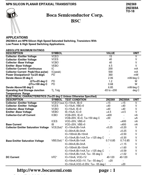
ft
VCE=10V,IC=10mA, f=100MHz
Output Capacitance
Cobo
VCB=5V, IE=0, f=140kHz
2N2369/2369A
2N2369 2N2369A UNIT
-
40-120
-
>30
-
>20
>20
-
>500 <4.0
>500 <4.0
MHZ pF
Turn on Time Turn off Time
40-120 -
>20
UNIT V V V V nA uA nA nA V V V V V V V V V
page : 1
元器件交易网
ELECTRICAL CHARACTERISTICS (Ta=25 deg C Unless Otherwise Specified)
DESCRIPTION
SYMBOL TEST CONDITION
2N2369
Collector -Emitter Voltage
VCEO*(sus)IC=10mA, IB=0
>15
Collector -Emitter Voltage
VCES
IC=10uA, VBE=0
>40
Collector -Base Voltage
Base Emitter Saturation Voltage
VBE(Sat) * IC=10mA,IB=1mA
0.7-0.85
IC=30mA,IB=3mA
-
IC=100mA,IB=10mA
-
IC=10mA,IB=1mA,Ta= +125 deg C -
ULN2069B中文资料
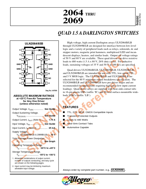
3115 Northeast Cutoff, Box 15036Worcester, Massachusetts 01615-0036 (508) 853-500042064 THRU 2069 QUAD 1.5 A DARLINGTONSWITCHES2064 THRU 2069QUAD 1.5 A DARLINGTON SWITCHES115 Northeast Cutoff, Box 15036Worcester, Massachusetts 01615-0036 (508) 853-500082064 THRU 2069QUAD 1.5 A DARLINGTONSWITCHES9ULN2064B, ULN2065B, ULN2068B, and ULN2069BDimensions in Inches (controlling dimensions)Dimensions in Millimeters(for reference only)NOTES:1.Exact body and lead configuration at vendor ’s option within limits shown.2.Lead spacing tolerance is non-cumulative.3.Lead thickness is measured at seating plane or below.4.Webbed lead frame. Leads 4, 5, 12, and 13 are internally one piece.5.Supplied in standard sticks/tubes of 25 devices.Dwg. MA-001-17A mm1618Dwg. MA-001-17A in16182064 THRU 2069QUAD 1.5 A DARLINGTON SWITCHES115 Northeast Cutoff, Box 15036Worcester, Massachusetts 01615-0036 (508) 853-500010Dwg. MA-008-21A mm1.27BSCNOTE 1NOTE 3ULN2064LB, ULN2065LB, ULN2068LB, and ULN2069LB(add “TR” to part number for tape and reel)Dimensions in Inches (for reference only)Dimensions in Millimeters (controlling dimensions)NOTES:1.Exact body and lead configuration at vendor ’s option within limits shown.2.Lead spacing tolerance is non-cumulative.3.Webbed lead frame. Leads 4 through 7 and 14 through 17 are internally one piece.4.Lead thickness is measured at seating plane or below.5.Supplied in standard sticks/tubes of 37 devices or add “TR ” to part number for tape and reel.Dwg. MA-008-21A inBSCNOTE 1NOTE 32064 THRU 2069QUAD 1.5 A DARLINGTON SWITCHES 11The products described here are manufactured under one or moreU.S. patents or U.S. patents pending.Allegro MicroSystems, Inc. reserves the right to make, from time totime, such departures from the detail specifications as may be requiredto permit improvements in the performance, reliability, ormanufacturability of its products. Before placing an order, the user iscautioned to verify that the information being relied upon is current.Allegro products are not authorized for use as critical componentsin life-support devices or systems without express written approval.The information included herein is believed to be accurate andreliable. However, Allegro MicroSystems, Inc. assumes no responsi-bility for its use; nor for any infringement of patents or other rights ofthird parties which may result from its use.2064 THRU 2069QUAD 1.5 A DARLINGTON SWITCHES115 Northeast Cutoff, Box 15036Worcester, Massachusetts 01615-0036 (508) 853-500012POWER SINK DRIVERS IN ORDER OF 1) OUTPUT CURRENT, 2) OUTPUT VOLTAGE, 3) NUMBER OF DRIVERSOutput Ratings *Features Serial Latched Diode Internal mA V #Input Drivers Clamp Outputs Protection Part Number †75178X X –constant current –62751716X X –constant current –627610020 8–––saturated –25953032X X –––58334032X X –saturated –583250 8addressable decoder/driver DMOS –6B25950 8–X –DMOS –6B27350 8X X –DMOS –6B595120248X X –constant current –627725050 8addressable decoder/driver DMOS –625950 8–X –DMOS –627350 8X X –DMOS –659550 8––X saturated –259660 4––X saturated X 255735050 4–X X ––580050 7––X ––200350 7––X ––200450 8––X ––280350 8–X X ––580150 8X X –––582150 8X X X ––584150 8addressable decoder/driver DMOS –6A25950 8X X –DMOS –6A59580 8X X –––582280 8X X X ––584295 7––X ––202395 7––X ––20244503028dual 4- to 14-line decoder/driver ––681760060 4–––saturated X 254760 4––X saturated X 2549 and 255970060 4––X saturated X 254375050 8––X saturated –2597100046 4stepper motor controller/driver MOS –7024 and 7029120046 4microstepping controller/driver MOS –7042125050 4stepper motor translator/driver –X 5804180050 4––X ––2540300046 4stepper motor controller/driver MOS –702646 4microstepping controller/driver MOS –7044400050 4––X ––2878 *Current is maximum specified test condition, voltage is maximum rating. See specification for sustaining voltage limits or over-current protection voltage limits. †Complete part number includes additional characters to indicate operating temperature range and package style.。
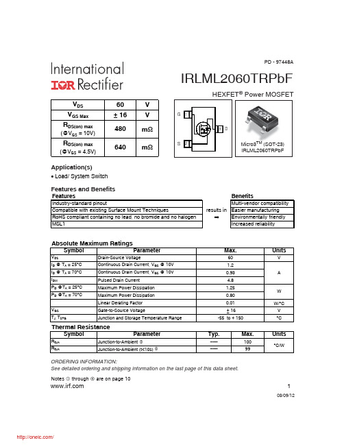
IRLML2060TRPBF;中文规格书,Datasheet资料
1
03/09/12
/
IRLML2060TRPbF
Electric Characteristics @ TJ = 25°C (unless otherwise specified)
Symbol
V(BR)DSS
Parameter
Min. Typ. Max. Units
PD - 97448A
IRLML2060TRPbF
HEXFET® Power MOSFET
VDS VGS Max RDS(on) max
(@VGS = 10V)
60 ± 16 480 640
V V m m
6 * '
Micro3TM (SOT-23) IRLML2060TRPbF
RDS(on) max
Conditions
VGS = 0V, ID = 250μA VGS = 10V, ID = 1.2A VDS = VGS, ID = 25μA VDS = 60V, VGS = 0V VDS = 60V, VGS = 0V, TJ = 125°C VGS = 16V VGS = -16V VDS = 25V, ID = 1.2A ID = 1.2A VDS = 30V VGS = 4.5V VDD = 30V ID = 1.2A RG = 6.8 VGS = 4.5V VGS = 0V VDS = 25V ƒ = 1.0MHz
Fig 6. Typical Gate Charge vs. Gate-to-Source Voltage
10
100
ID, Drain-to-Source Current (A)
ISD, Reverse Drain Current (A)
MBRB2060CT中文资料

MBRB2035CT THRU MBRB2060CTSCHOTTKY RECTIFIERReverse Voltage - 35 to 60 Volts Forward Current -20.0 AmperesFEATURES♦Plastic package has Underwriters Laboratory Flammability Classification 94V-0♦ Dual rectifier construction, positive center tap ♦ Metal silicon junction,majority carrier conduction ♦ Low power loss,high efficiency♦ High current capability, low forward voltage drop ♦ High surge capability♦ Guardring for overvoltage protection♦ For use in low voltage, high frequency inverters, free wheeling, and polarity protection applications ♦ High temperature soldering in accordance with CECC 802 / Reflow guaranteedMECHANICAL DATACase:JEDEC TO-263AB molded plasticTerminals:Leads solderable per MIL-STD-750,Method 2026Polarity:As marked Mounting Position:AnyWeight:0.08 ounce, 2.24 gramsMAXIMUM RATINGS AND ELECTRICAL CHARACTERISTICSRatings at 25°C ambient temperature unless otherwise specified.SYMBOLS MBRB2035CT MBRB2045CT MBRB2050CTMBRB2060CT UNITSMaximum repetitive peak reverse voltage V RRM 35455060Volts Maximum working peak reverse voltage V RWM 35455060Volts Maximum DC blocking voltageV DC 35455060Volts Maximum average forward rectified current at T C =135°CI (AV)20.0Amps Peak repetitive forward current per leg at T C =135°C (rated V R , sq. wave 2.0 KH Z )I FRM 20.0Amps Peak forward surge current 8.3ms single half sine-wave superimposed on rated load (JEDEC Method)I FSM 150.0AmpsPeak repetitive reverse surge current (NOTE 1)I RRM 1.00.5Amps Maximum instantaneous I F =10A, T C =25°C _0.80forward voltage per leg atI F =10A, T C =125°C V F0.570.70Volts(NOTE 2)I F =20A, T C =25°C 0.840.95I F =20A, T C =125°C0.720.85Maximum instantaneous reverse current at rated DC blocking voltage per leg T C =25°CI R 0.10.15mA T C=125°C 15.0150.0Voltage rate of change, (rated V R )dv/dt 10,000V/µs Typical thermal resistance per leg (NOTE 3)R ΘJC 2.0°C/W Operating junction temperature range T J -65 to +150°C Storage temperature rangeT STG-65 to +175°CNOTES:(1) 2.0µs pulse width, f=1.0KH Z(2) Pulse test: 300µs pulse width, 1% duty cycle (3) Thermal resistance from junction to case per leg4/98Dimensions in inches and (millimeters)NEW PRODUCTNEW PRODUCT NEW PRODUCT元器件交易网元器件交易网。
2060铝锂合金FSW接头微观组织和力学性能
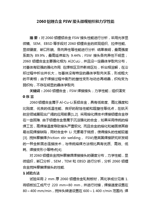
2060铝锂合金FSW接头微观组织和力学性能摘要:对2060铝锂铝合金FSW接头性能进行分析,采用光学显微镜、SEM、EBSD等手段对2060铝锂合金的微观组织、拉伸性能、显微硬度、断口形貌、各向异性等性能进行分析. 结果表明,最高强度系数为89.9%,最高延伸率为9.44%;FSW接头各向异性不明显;2060铝锂合金主要强化相为Al2CuLi,并且沿一定晶体学取向分布,对基体有较强的强化作用. 在焊核区及热影响区处,析出相溶解,在冷却过程中析出并长大,与基体没有特定的晶体学取向关系,形成粗大的平衡相;由于焊接过程中剧烈的塑性变形与动态再结晶,织构变为弱织构,不存在明显的晶体学取向.关键词:2060铝锂合金;FSW焊接接头;力学性能;组织演变0 序言2060铝锂合金属于Al-Cu-Li系铝合金,具有低密度、高比强度和比刚度、优良的低温性能、良好的耐蚀性能和超塑性等优点,在航天航空领域展现出广阔的应用前景[1,2]. 采用熔化焊技术焊接铝锂合金存在一些困难. 由于铝锂合金是属于沉淀强化的合金,如果采用传统的熔焊工艺,高焊接温度导致接头严重软化. 而且合金的熔化和凝固使其容易出现焊接缺陷,同时合金中Li元素易于烧损,使得接头的性能较差[3]. 搅拌摩擦焊(friction stir welding,FSW)是英国焊接研究所发明的一种全新固态连接技术,与传统熔焊方法相比具有优质、高效、低耗、焊接变形小等特点[4].对2060铝锂合金搅拌摩擦焊焊接接头的硬度分布,力学性能,显微组织,断口分析,SEM,TEM和EBSD进行分析,分析2060铝锂合金搅拌摩擦焊接头的性能.1 试验方法试验采用2 mm厚2060铝锂合金轧制板材,其化学成分见表1. 将铝板加工成尺寸220 mm×80 mm,并进行对接,焊接速度设置在80~400 mm/min,搅拌头转速设置在600~1 400 r/min范围内. 焊接头轴肩直径为10 mm,搅拌针直径为3.6 mm,搅拌针长为1.86 mm,轴肩形貌采用双圆环,搅拌针形貌为锥形带螺纹. 拉伸试样尺寸按国家标准GB228-2002《金属材料室温拉伸试验方法》执行,室温条件下每个工艺参数选3个试样,在型号为AG-10TA万能试验机上进行拉伸强度试验;型号HBRVU-187.5布洛维光学硬度仪测硬度,所加载荷为2.94 N;并在Sirion 200场发射扫描电镜进行EBSD观察. 在Tecnai G220透射电镜下观察焊接接头不同区域的微观组织.表1 2060铝锂合金化学成分(质量分数,%)Table 1 Chemical compositions of 2060LiSiFeCuMnMgCrZnAgAl0.720.0250.0263.560.30.7 2<>2 试验结果与分析2.1 显微组织观察转速800 r/min、焊接速度80 mm/min的FSW接头各区的组织如图1所示,可以看出,母材为伸长的条状组织,为典型的轧制组织,如图1a所示;焊核区为细小均匀的等轴晶,在搅拌摩擦焊接过程中,焊核区的温度较高,在搅拌针的作用下发生剧烈塑性变形,致使该区的组织发生动态再结晶,生成细小的等轴晶粒,如图1b所示;前进侧热力影响区和后退侧热力影响区的组织如图1c,图1d所示,其组织差别较大,热力影响区与焊核区的分界线更加明显,这主要是因为前进侧热影响区的材料经受搅拌头的剪切作用,塑性变形更加剧烈,导致其分界线更加明显.图1 搅拌摩擦焊接头的组织Fig.1 Microstructure of base metal and FSW joint2.2 焊接接头的拉伸性能对不同工艺参数下的焊接试样进行拉伸试验,试验结果见表2,断口形貌如图2所示.表2 不同焊接参数下2060铝锂合金的拉伸试验数据Table 2 Tensile strength of 2060 in different parameter at room temperature转速n/(r·min-1)焊接速度v/(mm·min-1)接头抗拉强度RmW/MPa断后伸长率A(%)强度系数RmW/RmBM(%)600804139.1481.16002004269.1283.5600 4004399.4486.2800804579.1389.88002004599.4289.91 000804378.8585.910002003445.5767.510004004258.79 83.412002002584.2950.71400804458.2387.3140020029 73.4258.3以800 r/min的转速焊接时,抗拉强度最接近母材的抗拉强度,提高或者降低旋转速度,抗拉强度呈现降低的趋势. 断后伸长率的变化趋势与抗拉强度一致. 同时将不同工艺下接头的室温抗拉强度与母材的室温抗拉强度作比较,每一工艺下的抗拉强度与母材的抗拉强度的比值(RmW/RmBM)差异较大,如果转速高于800 r/min,试样的抗拉强度明显下降,如以1 400 r/min,焊接速度200 mm/min焊接时,其抗拉强度只有母材强度的58.3%. 另外,焊接速度在80~400 r/min之间变化,旋转速度在600 ~800 r/min之间变化时,其抗拉强度都在基体材料的85%以上,也就说很接近母材的强度,断裂发生在热力影响区. 造成试样断裂的原因是热力影响区的金属在热和力的共同作用下发生软化,从而使性能降低.图2 不同焊接参数的2060铝锂合金断口形貌Fig.2 Fracture morphology of 2060 Al-Li alloy at different welding parameters当焊接速度和转速不同时,断口形貌差别较大,在转速600 r/min,焊接速度80 mm/min下,断口表面分布不同尺寸、不同深浅、不同形状的韧窝和一些剪切带,断口呈剪切断裂特征;在转速800 r/min,焊接速度80 mm/min下,断口出现等轴的大小不均的韧窝带,热影响区晶粒为层状分布的细长晶粒,因此断口呈层状结构;在转速1 000 r/min,焊接速度200 mm/min下,断口的韧窝较小,塑性断裂特征不明显,所以强度系数较低.2.3 显微硬度从图3可以看出,2060铝锂合金搅拌摩擦焊缝硬度从大到小依次为BM,WNZ,TMAZ,HAZ. 80 mm/min速度时,热影响区与焊核区的显微硬度相差不大,远低于母材的硬度. 当转速升高时,焊核区硬度升高,同时,热影响显微硬度最低点向远离焊核中心的方向移动. 200 mm/min速度时,焊核区硬度高于热影响区的显微硬度最低点,在焊核区形成强化相,提高了接头显微硬度,但远低于母材硬度. 当转速升高时,焊核区显微硬度基本不变,但热影响显微硬度最低点向远离焊核区中心的方向移动.图3 不同焊接参数下显微硬度分布Fig.3 Microhardness under different welding parameters2.4 微观组织分析图4a所示为母材的TEM 像及相应的电子衍射花样,在2060铝锂合金中有细小的针状和颗粒状组织析出,结合XRD结果可知主要强化相为Al2CuLi,非常细小,并且沿一定晶体学取向分布,对基体有较强的强化作用. Mg原子优先存在于Li 原子周围,并吸引空位,形成Mg-Li-空位团簇. 这些原子团簇进一步吸引Li原子,为Al2CuLi的形成提供形核点.图4b和图4c为FSW后的TEM像,在焊核处由于搅拌针的强烈搅拌作用,温度急剧升高,发生严重的塑性变形,将加剧析出相的溶解. 在冷却过程中析出并长大,形成粗大的平衡相. 在热影响区,温度低于焊核温度,材料没有强烈的塑性变形,析出相先粗化后溶解,并且由于析出相的大量析出,与基体没有特定的晶体学取向关系,在该区域析出的析出相为平衡相. 焊核区由没有明显织构的等轴晶组成,并且晶粒尺寸细小. 由于焊接过程中剧烈的塑性变形与动态再结晶,织构变为弱织构,没有明显的晶体学取向. 虽然焊核区发生了动态再结晶,形成细小等轴再结晶晶粒,具有细晶强化作用,但不足以弥补析出相溶解带来的硬度和强度的下降. 与Moran[5]关于铝锂合金分析的结果是一样的.图5为2060铝锂合金晶粒取向分布图,从图5中可以看出,母材是2 mm厚的轧制板材,织构类型是(110)[112]的黄铜织构. 随转速提高晶粒尺寸逐渐增大,并且提高转速即提高热输入不能明显的消除低角度晶界. 焊核区织构类型是(111)[112]的高斯织构. 焊核区经历了剧烈的剪切变形,织构类型属于剪切织构. 但同时焊核区又在剪切变形和高温的作用下发生了动态再结晶,降低了织构强度.图4 不同区域的投射电子显微组织Fig.4 Organization chart of SEM图5 晶粒取向图Fig.5 Grain boundary orientation distribution map从图6可以看出,母材中低角度晶界的含量较高,形成的具有高角晶界的晶粒的取向差较大,较大的晶粒中存在较多的亚晶. 焊核区晶粒错配角分布较均匀,焊核区由大小均匀的再结晶晶粒组成. 随着转速的提高,高角度晶界的比例也逐渐提高,在高热输入量条件下,再结晶晶粒的长大促使了部分低角度晶界向高角度晶界转变.图6 晶界取向差分分布Fig.6 Grain boundary misorientation distribution curve图7为2060铝锂合金母材和FSW焊核区的微观织构图,可以看出,母材中存在强烈的<111>方向织构,焊核区存在弱的织构,FSW 参数对焊核区织构的影响不显著. 分析其原因是,母材是热轧板材,因此存在强烈的织构,在FSW作用下,材料塑化变形呈圆周运动,形成的再结晶晶粒的取向是随机的.图7 微观织构图Fig.7 Texture pole figures3 结论(1) 高转速下接头组织中有大量块体颗粒存留,降低了接头强度;低转速下因轴肩与焊接材料间摩擦机制作用在接头成形中的比例减小,层间结合力减弱,最高抗拉强度可以达到母材的89.9%.(2) 无论是母材还是搅拌摩擦焊接头,从常规力学性能考查,各向异性不明显. 母材的织构为(110) [112]黄铜织构,焊核区变为(111)[112]高斯织构,织构强度也降低.(3) 2060铝锂合金主要强化相为Al2CuLi,非常细小,并且沿一定晶体学取向分布,对基体有较强的强化作用. 在焊核区及热影响区处,析出相溶解,在冷却过程中析出并长大,与基体没有特定的晶体学取向关系,形成粗大的平衡相.(4) 2060铝锂合金焊核区由没有明显织构的等轴晶组成,并且晶粒尺寸细小. 由于焊接过程中剧烈的塑性变形与动态再结晶,织构变为弱织构,不存在明显的晶体学取向.。
2N7002中文资料(Diodes)中文数据手册「EasyDatasheet - 矽搜」
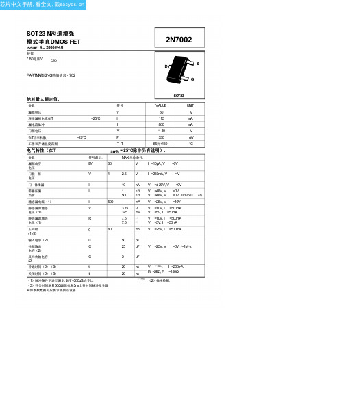
反向传输电容
(2)
C
5
pF
导通时间(2)(3)
t
关闭时间(2)(3)
t
20 ns V 30V, I =200mA 20 ns R =25Ω, R =150Ω
(1)脉冲条件下进行测定.宽度=300μS.占空比 (3)开关时间测量50Ω源阻抗和5ns上升时间脉冲发生器
辣妹参数数据可应要求提供该设备
2% (2)抽样检测.
门 - 体泄漏
零栅压漏 当前
I
10 nA V =± 20V, V =0V
I
1
µA V =48V, V =0V
500 µA V =48V, V =0V, T=125°C (2)
通态漏电流(1)
I
500
mA V =25V, V =10V
静态漏源通态
电压(1)
V
3.75 V V =10V, I =500mA
芯片中文手册,看全文,戳
SOT23 N沟道增强 模式垂直DMOS FET
ISSUE 4 – 2006年 4月
特征
* 60电压V CEO
PARTMARKING详细信息 - 702
2N7002
S D
G
绝对最大额定值.
SOT23
参数
符号
VALUE
UNIT
漏源电压
V
60
V
连续漏极电流在T
=25°C
I
115
mA
漏电流脉冲
I
800
mA
门源电压
V
± 40
V
在T功率耗散
=25°C
P
330
mW
工作和存储温度范围
T :T
Bq2060 eeprom的定义(以4串锂电6000mah为例)
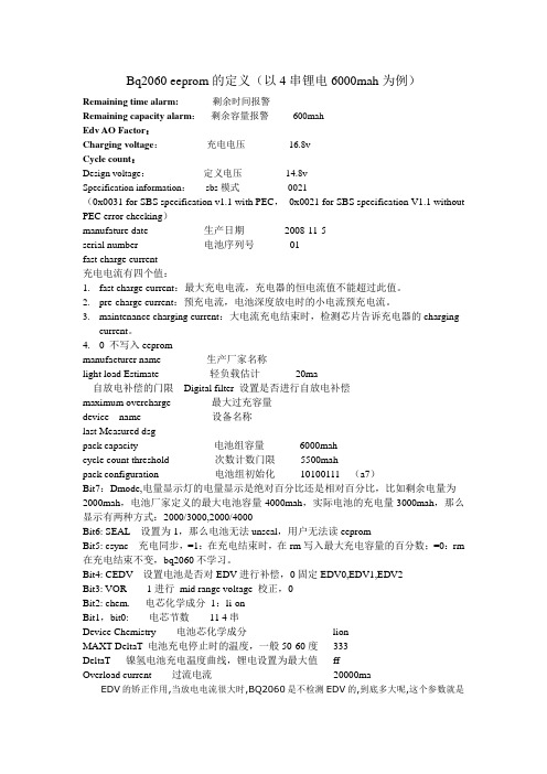
Bq2060 eeprom的定义(以4串锂电6000mah为例)Remaining time alarm:剩余时间报警Remaining capacity alarm:剩余容量报警600mahEdv AO Factor:Charging voltage:充电电压16.8vCycle count:Design voltage:定义电压14.8vSpecification information:sbs模式0021(0x0031 for SBS specification v1.1 with PEC,0x0021 for SBS specification V1.1 without PEC error checking)manufature date 生产日期2008-11-5serial number 电池序列号01fast charge current充电电流有四个值:1.fast charge current:最大充电电流,充电器的恒电流值不能超过此值。
2.pre-charge current:预充电流,电池深度放电时的小电流预充电流。
3.maintenance charging current:大电流充电结束时,检测芯片告诉充电器的chargingcurrent。
4.0 不写入eeprommanufacturer name 生产厂家名称light load Estimate 轻负载估计20ma自放电补偿的门限Digital filter 设置是否进行自放电补偿maximum overcharge 最大过充容量device name 设备名称last Measured dsgpack capacity 电池组容量6000mahcycle count threshold 次数计数门限5500mahpack configuration 电池组初始化10100111 (a7)Bit7:Dmode,电量显示灯的电量显示是绝对百分比还是相对百分比,比如剩余电量为2000mah,电池厂家定义的最大电池容量4000mah,实际电池的充电量3000mah,那么显示有两种方式:2000/3000,2000/4000Bit6: SEAL 设置为1,那么电池无法unseal,用户无法读eepromBit5: csync 充电同步,=1:在充电结束时,在rm写入最大充电容量的百分数;=0:rm 在充电结束不变,bq2060不学习。
R2J20602NP中文资料

R2J20602NP中文资料R2J20602NPIntegrated Driver – MOS FET (DrMOS)REJ03G1480-0300Rev.3.00Jun 30, 2008 DescriptionThe R2J20602NP multi-chip module incorporates a high-side MOS FET, low-side MOS FET, and MOS-FET driver in a single QFN package. The on and off timing of the power MOS FET is optimized by the built-in driver, making this device suitable for large-current buck converters. The chip also incorporates a high-side bootstrap Schottky barrier diode (SBD), eliminating the need for an external SBD for this purpose.Integrating a driver and both high-side and low-side power MOS FETs, the new device is also compliant with the package standard “Integrated Driver –MOS FET (DrMOS)” pro posed by Intel Corporation.FeaturesBuilt-in power MOS FET suitable for applications with 12 V input and low output voltageBuilt-in driver circuit which matches the power MOS FETBuilt-in tri-state input function which can support a number of PWM controllersVIN operating-voltage range: 16 V maxHigh-frequency operation (above 1 MHz) possibleLarge average output current (Max. 40 A)Achieve low power dissipation (About 4.4 W at 1 MHz, 25 A) Controllable driver: Remote on/offBuilt-in Schottky diode for bootstrappingLow-side drive voltage can be independently setSmall package: QFN56 (8 mm × 8 mm × 0.95 mm)Terminal Pb-freeOutlineBlock DiagramNotes: 1. Truth table for the DISBL# pin.DISBL# Input Driver Chip Status “L” Shutdown (GL, GH = “L”) “Open”Shutdown (GL, GH = “L”) “H”Enable (GL, GH = “Active”)2. UVL Output Logic LevelPin ArrangementNote: All die-pads (three pads in total) should be soldered to PCB.Pin DescriptionPin Name Pin No. Description RemarksCGND 1, 6, 51, Tab Control signal ground Should be connected to PGND externallyNC 2, 53 No connectVLDRV 3 Low side gate supply voltage For 5 V to 12 V gate drive voltage for Low sidegate driverVCIN 4 Control input voltage (+12 V input)Driver Vcc input BOOT 5 Bootstrap voltage pin T o be supplied +5 V through internal SBDGH 7 High side gate signal Pin for MonitorVIN 8 to 20, Tab Input voltageVSWH 21, 40 to 50, Tab Phase output/Switch outputPGND 22 to 39 Power groundGL 52 Low side gate signal Pin for MonitorReg5V 54 +5 V logic power supply outputDISBL# 55 Signal disable Disabled when DISBL# is “L”PWM 56 PWM drive logic inputAbsolute Maximum Ratings(Ta = 25°C)Item Symbol Rating Units NotePt(25) 25 W 1Power dissipation Pt(110) 8 W 1Average output current Iout 40 A VIN (DC) –0.3 to +16 2Input voltage VIN (AC) 20 V 2, 6VCIN (DC) –0.3 to +16 2Supply voltage VCIN (AC) 20 V 2, 6VLDRV (DC) –0.3 to +16 2Low side driver voltage VLDRV (AC) 20 V 2, 6VSWH (DC) 16 2Switch node voltage VSWH (AC) 20 V 2, 6VBOOT (DC) 22 2BOOT voltage VBOOT (AC) 25 V 2, 6DISBL# voltage Vdisble –0.3 to VCIN V 2 –0.3 to +5.5 V 2, 4 PWM voltage Vpwm –0.3 to +0.3 V 2, 5Reg5V current Ireg5V –10 to +0.1 mA 3 Operating junction temperature Tj-opr –40 to +150 °C Storage temperature Tstg–55 to +150°CNotes: 1. Pt(25) represents a PCB temperature of 25°C, and Pt(110) represents 110°C. 2. Rated voltages are relative to voltages on the CGND and PGND pins. 3. For rated current, (+) indicates inflow to the chip and (–) indicates outflow.4. This rating is when UVL (Under Voltage Lock out) is ineffective (normal operation mode).5. This rating is when UVL (Under Voltage Lock out) is effective (lock out mode).6. The specification values indicated “AC” are limited within 100 ns.Electrical CharacteristicsTypical ApplicationTest CircuitTypical DataTypical Data (cont.)Description of OperationThe DrMOS multi-chip module incorporates a high-side MOS FET, low-side MOS FET, and MOS-FET driver in a single QFN package. Since the parasitic inductance between each chip is extremely small, the module is highly suitable for use in buck converters to be operated at high frequencies. The control timing between the high-side MOS FET, low-side MOS FET, and driver is optimized so that high efficiency can be obtained at low output-voltage.DriverThe driver has two types of power-supply voltage input pin, VCIN and VLDRV. VCIN supplies the operating voltage to theinternal logic circuit. The low-side driving voltage is applied to VLDRV, so setting of the gate-driving voltage for the low-side MOS FET is independent of the voltage on VCIN. The VLDRV setting voltage is from 5 V to 16 V.The VCIN pin is connected to the UVL (under-voltage lockout) module, so that the driver is disabled as long as VCIN is 7.4 V or less. On cancellation of UVL, the driver remains enabled until the UVL input is driven to 7.0 V or less. The signal on pin DISBL# also enables or disables the circuit. When UVL disables the circuit, the built-in 5 V regulator does not operate, but when the signal on DISBL# disables the circuit, only output-pulse generation is terminated, and the 5 V regulator is not disabled.StateVCIN VLDRV DISBL# Reg5V DriverL > 5 V ?0 Disable (GL, GH = L)H > 5 V L 5 V Disable (GL, GH = L)H > 5 V H 5 V ActiveH > 5 V Open 5 V Disable (GL, GH = L)Voltages from –0.3 V to VCIN can be applied to the DISBL# pin, so on/off control by a logic IC or the use of a resistor, etc., to pull the DISBL# line up to VCIN are both possible.The built-in 5 V regulator is a series regulator with temperature compensation. The voltage output by this regulator determines the operating voltage of the internal logic and gate-voltage swing for the high-side MOS FET. A ceramic capacitor with a value of 0.1 μF or more must be connected between the CGND plane and the Reg5V pin.The PWM pin is the signal input pin for the driver chip. The input-voltage range is –0.3 V to (Reg5V + 3 V). When the PWM input is high, the gate of the high-side MOS FET (GH) is high andthe gate of the low-side MOS FET (GL) is low.PWM GH GLL L HH H LThe PWM input is TTL level and has hysteresis. When the PWM input signal is abnormal, e.g., when the signal route from the control IC is abnormal, the tri-state function turns off the high- and low-side MOS FETs. This function operates when the PWM input signal stays in the input hysteresis window for 240 ns (typ.). After the tri-state mode has been entered and GH and GL have become low, a PWM input voltage of 4.0 V or more is required to make the circuit return to normal operation.Figure 1For the high-side driver, the BOOT pin is the power-supply voltage pin and voltage VSWH provides a standard for operation of the high-side driving circuit. Consequently, the differencebetween the voltage on the BOOT and VSWH pins becomes the gate swing for the high-side MOS FET. Connect a bootstrap capacitor between the BOOT pin and the VSWH pin. Since the Schottky barrier diode (SBD) is connected between the BOOT and Reg5V pins, this bootstrap capacitor is charged up to 5 V. When the high-side MOS FET is turned on, voltage VSWH becomes equal to VIN, so VBOOT is boosted to VSWH + 5 V.The GH and GL pins are the gate-monitor pins for each MOS FET.MOS FETsThe MOS FETs incorporated in R2J20602NP are highly suitable for synchronous-rectification buck conversion. For the high-side MOS FET, the drain is connected to the VIN pin and the source is connected to the VSWH pin. For the low-side MOS FET, the drain is connected to the VSWH pin and the source is connected to the PGND pin.PCB Layout ExampleFigure 2 shows an example of a PCB layout for the R2J20602NP in application. The several ceramic capacitors (e.g.10 μF) close to VIN and PGND can be expected to decrease switching noise and improve efficiency. In that case, all sections of the GND pattern must be connected with other PCB layers via low impedances. Moreover, the wide VSWH pattern can be expected to have the effect of dissipating heat from the low-side MOS FET.When R2J20602NP is mounted on small circuit boards, such as those for point-of-load (POL) applications, heating of the device can be alleviated by adding thermal via-holes under the VIN and VSWH pads.Figure 2 R2J20602NP PCB Layout Example (Top View) Footprint Example(Unit: mm)Figure 3 Footprint ExamplePackage DimensionsRefer to "/en/network " for the latest and detailed information.Renesas Technology America, Inc.450 Holger Way, San Jose, CA 95134-1368, U.S.A Tel: <1> (408) 382-7500, Fax: <1> (408) 382-7501Renesas Technology Europe LimitedDukes Meadow, Millboard Road, Bourne End,Buckinghamshire, SL8 5FH, U.K.Tel: <44> (1628) 585-100, Fax: <44> (1628) 585-900Renesas Technology (Shanghai) Co., Ltd.Unit 204, 205, AZIACenter, No.1233 Lujiazui Ring Rd, Pudong District, Shanghai, China 200120Tel: <86> (21) 5877-1818, Fax: <86> (21) 6887-7858/7898Renesas Technology Hong Kong Ltd.7th Floor, North T ower, World Finance Centre, Harbour City, Canton Road, Tsimshatsui, Kowloon, Hong Kong Tel: <852> 2265-6688, Fax: <852> 2377-3473Renesas Technology Taiwan Co., Ltd.10th Floor, No.99, Fushing North Road, Taipei, Taiwan Tel: <886> (2) 2715-2888, Fax: <886> (2) 3518-3399Renesas Technology Singapore Pte. Ltd.1 Harbour Front Avenue, #06-10, Keppel Bay Tower, Singapore 098632 Tel: <65> 6213-0200, Fax: <65> 6278-8001Renesas Technology Korea Co., Ltd.Kukje Center Bldg. 18th Fl., 191, 2-ka, Hangang-ro, Yongsan-ku, Seoul 140-702, Korea Tel: <82> (2) 796-3115, Fax: <82> (2) 796-2145Renesas Technology Malaysia Sdn. BhdUnit 906, Block B, Menara Amcorp, Amcorp Trade Centre, No.18, Jln Persiaran Barat, 46050 Petaling Jaya, Selangor Darul Ehsan, Malaysia Tel: <603> 7955-9390, Fax: <603> 7955-9510 RENESAS SALES OFFICES。
2SA2060(TE12L,F);中文规格书,Datasheet资料

−0.4
−0.8 −1.2
−1.6
−2
−2.4
Collector-emitter voltage VCE (V)
VCE (sat) – IC
−1 Common emitter IC/IB = 30 Single nonrepetitive pulse
−0.1
−0.01
Ta = 100°C
−55 25
25 −55
10
1 −0.001
−0.01
Common emitter VCE = −2 V Single
nonrepetitive
pulse
−0.1
−1
−10
Collector current IC (A)
VBE (sat) – IC
−10 Common emitter IC/IB = 30 Single nonrepetitive pulse
1.0
Tj
150
°C
TOSHIBA
2-5K1A
Weight: 0.05 g (typ.)
Storage temperature range
Tstg
−55 to 150
°C
Note 1: Mounted on an FR4 board (glass epoxy, 1.6 mm thick, Cu area: 645 mm2)
Collector-emitter voltage VCE (V)
Collector current IC (A)
VCEO max
/
4
2009-12-21
2SA2060
RESTRICTIONS ON PRODUCT USE
• Toshiba Corporation, and its subsidiaries and affiliates (collectively “TOSHIBA”), reserve the right to make changes to the information in this document, and related hardware, software and systems (collectively “Product”) without notice.
BQ2060中文资料
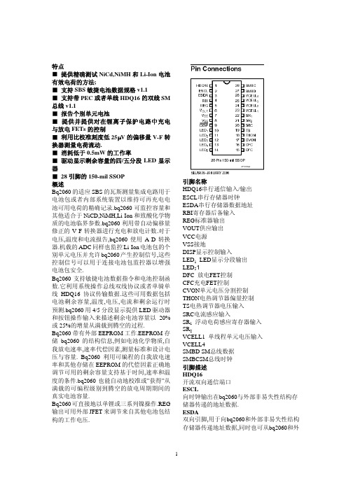
VCELL3–VCELL4的一半.为了减少电池的电 流消耗,在测量期间CVON输出可用于连接分 配器与单元.当单元被测量或被低驱动,CVON 对于250ms是高阻抗的(12.5%工作周期).请看 表1.
3
电流 Bq2060的SRC输入测量电池的充电和放电电 流.SRC ADC输入每隔2秒钟就把串行感应电 阻器转换成电流信号并把结构存储在函数
Current().SBC的完全输入范围限制在±300mV, 在表2中有显示. 温度
接连着NTC电热调节器的bq2060的TS输入测 量电池温度,在图1中有显示.bq2060在函数 Temperature()中记录温度.当bq2060每隔2秒钟 抽取TS输入的样品时,THON可用于把电热调 节器与偏源极连接起来.当温度被测量或被低 驱动时,THON持续60ms为高阻抗. 瓦斯测量操作
LED1– LED5 LED 每个输出可驱动一个外部LED
DFC 输出以控制Li-Ion包保护电路的放电FET.
CFC 输出以控制Li-Ion包保护电路的充电FET.
CVON 在单元电压测量期间,输出用于控制外部FETs 把单元与外部电压驱动器连接起来
THON 在温度测量期间,输出用于控制外部FETs连接 电热调节器的偏压电阻器.
和放电,bq2060还测量电池电压,温度和电流, 估计判断电池自我放电和监控电池低压
极.bq2060通过监控电池包负极与正极之间的 连接低值串行感应寄存器的电压来测量充电
和放电的活动性.通过监控随时间变化的电压 和随着环境和运行条件修正测量方法,可确定 用电池电荷. 图1显示了典型的基于bq2060的电池包应用. 这个电路由LED显示,电压与温度测量网 络,EEPROM连接,串行端口和感应寄存 器.EEPROM存储基本的电池包结构信息和测 量标准值.EEPROM必须正确设计以适于 bq2060的运行.表8显示了EEPROM存储器图 和概述了适用于bq2060的可编程函数. Bq2060使用NTC电热调节器(Semitec 103AT) 进行温度测量.bq2060利用电热调节器温度来 监控电池包温度,测试电池满载电荷条件和补 偿自我放电和充电/放电的电池效率. 测量
2SA1396中文资料(Inchange Semiconductor)中文数据手册「EasyDatasheet - 矽搜」
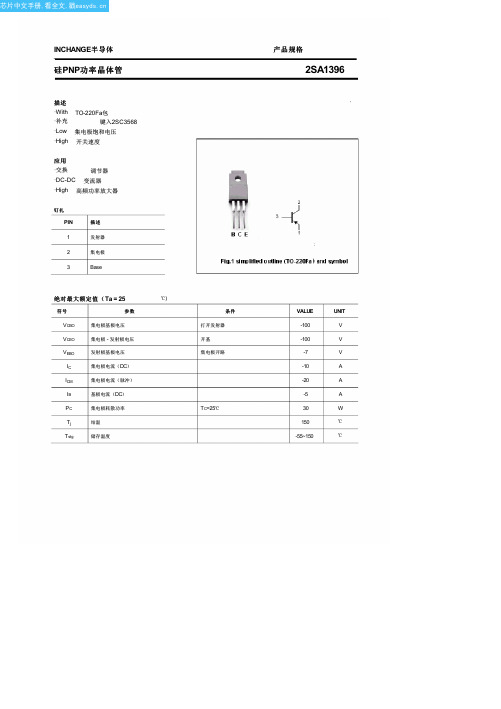
I CER
集电极截止电流
ICEX
集电极截止电流
I EBO
发射极截止电流
hFE-1 hFE-2 hFE-3
开关时间
DC电流增益 DC电流增益 DC电流增益
ton
开启时间
ts
贮存时间
tf
下降时间
hFE-2 分类
M
L
40-80 60-120
K 100-200
产品规格
2SA1396
条件
IC=-5A;I B=-0.5A;L=1mH IC=-5A; I B=-0.5A IC=-5A; I B=-0.5A VCB=-100V; I E=0 VCE=-100V; R BE=51Ω; Ta=125℃ VCE=-100V;V BE(off)=1.5V Ta=125℃ VEB=-5V; I C=0 IC=-0.5A ; V CE=-5V IC=-3A ; V CE=-5V IC=-5A ; V CE=-5V
IC=-5A ;I B1=-I B2=-0. 5A VCC≈50V;R L=10Ω
MIN TYP. MAX UNIT
-100
V
-0.6
V
-1.5
V
-10 μA
-1
mA
-0.01 -1
mA
-10 μA
40
200
40
200
20
0.5 μs
1.5
μs
0.5
μs
2
芯片中文手册,看全文,戳
芯片中文手册,看全文,戳
INCHANGE半导体
硅PNP功率晶体管
描述
·With ·补充 ·Low ·High
TO-220Fa包 键入2SC3568
2n6107参数

2N6107是一款PNP型的硅材料晶体管。
其主要参数包括集电极-发射极电压(VCEO)为-100V,集电极-基极电压(VCBO)为-100V,发射极-基极电压(VEBO)通常为-5V。
此外,它的连续集电极电流(IC)可以达到-8A,而集电极的耗散功率(Pc)在特定条件下可以达到80W。
在工作温度为25℃时,该晶体管的直流电流放大系数(hFE)通常在40到200之间。
此外,它的过渡频率(fT)和最大可用增益频率(fM)也是决定其在高频电路中性能的重要参数。
需要注意的是,虽然2N6107具有一定的通用性,但在具体的应用中,还需要根据电路的需求和条件来选择合适的晶体管。
同时,为了保证电路的稳定性和可靠性,还需要注意晶体管的工作温度和散热问题。
2N2920中文资料

TO–77 PACKAGE
PIN 1 – Collector 1 PIN 2 – Base 1 PIN 3 – Emitter 1 PIN 4 – Emitter 2 PIN 5 – Base 2 PIN 6 – Collector 2
ABSOLUTE MAXIMUM RATINGS
(Tamb = 25°C unless otherwise stated)
mV
1
1) Terminals not under test are open circuited under all test conditions. 2) The lower of the two readings is taken as hFE1.
Semelab plc.
Telephone +44(0)1455 556565. Fax +44(0)1455 552612. E-mail: sales@ Website:
mA
nA
W mmho
— pF
TRANSISTOR MATCHING CHARACTERISTICS Static Forward Current Gain VCE = 5V
Balance Ratio See Note 2. VCE = 5V VCE = 5V VCE = 5V TA1 = 25°C VCE = 5V TA1 = 25°C
Prelim. 9/95
INDIVIDUAL TRANSISTOR CHARACTERISTICS IC = 10mA Collector – Base Breakdown Voltage
V(BR)CEO* Collector – Emitter Breakdown Voltage IC = 10mA Emitter – Base Breakdown Voltage Collector Cut-off Current Collector Cut-off Current Emitter Cut-off Current IE = 10mA VCB = 45V
B201220600中文资料
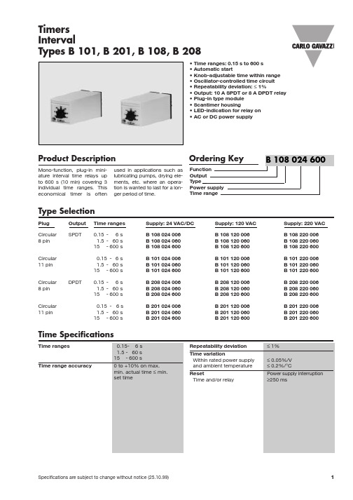
Power supply DC type Rated operational voltage 024 Rated insulபைடு நூலகம்tion voltage Rated transient protection volt. Consumption AC supply DC supply
Mode of Operation
Ordering Key
Function Output Type Power supply Time range
B 108 024 600
Type Selection
Plug Circular 8 pin Circular 11 pin Circular 8 pin Circular 11 pin DPDT Output SPDT Time ranges 0.15 - 6 s 1.5 - 60 s 15 - 600 s 0.15 - 6 s 1.5 - 60 s 15 - 600 s 0.15 - 6 s 1.5 - 60 s 15 - 600 s 0.15 - 6 s 1.5 - 60 s 15 - 600 s Supply: 24 VAC/DC B 108 024 006 B 108 024 060 B 108 024 600 B 101 024 006 B 101 024 060 B 101 024 600 B 208 024 006 B 208 024 060 B 208 024 600 B 201 024 006 B 201 024 060 B 201 024 600 Supply: 120 VAC B 108 120 006 B 108 120 060 B 108 120 600 B 101 120 006 B 101 120 060 B 101 120 600 B 208 120 006 B 208 120 060 B 208 120 600 B 201 120 006 B 201 120 060 B 201 120 600 Supply: 220 VAC B 108 220 006 B 108 220 060 B 108 220 600 B 101 220 006 B 101 220 060 B 101 220 600 B 208 220 006 B 208 220 060 B 208 220 600 B 201 220 006 B 201 220 060 B 201 220 600
SBL2060CT中文资料
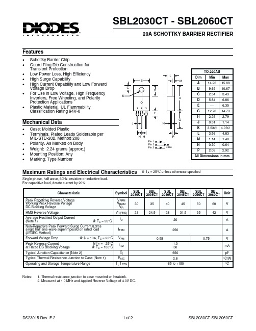
RqJC
Operating and Storage Temperature Range
Tj, TSTG
SBL 2030CT
30
21
SBL
SBL
SBL
2035CT 2040CT 2045CT
35
40
45
24.5
28
31.5
20
250
0.55 1.0 50 650 2.8
-65 to +150
SBL
SBL
L
3.56 4.83
M
1.14 1.40
N
0.30 0.64
P
2.03 2.92
All Dimensions in mm
Maximum Ratings and Electrical Characteristics @ TA = 25°C unless otherwise specified
Single phase, half wave, 60Hz, resistive or inductive load. For capacitive load, derate current by 20%.
Voltage Drop · For Use in Low Voltage, High Frequency
Inverters, Free Wheeling, and Polarity Protection Applications · Plastic Material: UL Flammability Classification Rating 94V-0
Peak Reverse Current at Rated DC Blocking Voltage
@TC = 25°C @ TC = 100°C
JUKI-2060各控制板卡的作用
JUKI-2060各控制板卡的作用一、CPU板CPU基板是控制整个装置的基板,其它基板通过CPCI母线,接口桥基板,VME总线接口进行连接。
二、XMP基板XMP基板和RMB(JGRMB基板和JHRMB基板)一起动作,是伺服马达和步进马达的控制基板。
XMP基板最多可以控制19轴的马达。
(1)从RMB基板输出16BIT的串行指今信号。
控制XY轴ZQ轴的AC伺服马达。
XY轴:用马达的旋转变换器控制速度。
计数电磁标尺控制定位。
ZQ轴:用马达的旋转变换器控制位置(2)从RMB基板输出脉冲指令。
控制中心马达。
后备马达。
自动宽度调马达的步进马达。
(3)检测紧急开关的开放。
既时停止XY轴。
ZQ轴。
(4)进行各轴原点和限制传感器的检测。
(5)伺服启动,电磁标尺的警报检测。
(6)安装有XY轴。
ZQ轴以及后备马达R轴的位置管理用计数器。
三、SYNONET连接基板SYNONET连接基板是JGRMB基板。
SAFETY基板。
CARRY连接基板以及各马达驱动器。
电磁标尺。
限制传感器间的信号连接基板。
(1)中转ZY4轴驱动器和XMP基板的信号。
其中警报信号由被绝缘处理的图像探头向SAFETY基板输出。
(2)中转电磁标尺和XMP基板的信号。
(3)XY轴的限制信号经JGRMB基板和SAFETY基板输出。
(4)中转中心马达。
后备马达。
自动宽度调整马达的驱动器和XMP基板的信号(经CARRY 中转基板)四、接口桥基板接口桥基板与CPCI接口和VME接口连接。
是从CPCI向VME存取的基板。
CPCI接口连接的基板:CPU基板。
XMP基板。
VME接口连接的基板:SAFETY,LIGHTCTRL,BASE-FEEDER,I/O CTRL,IP-X3,MCM (L),MCM(R)基板。
五、MCM基板本基板是元件中心用传感器(MNLA或FMLA)的控制和演算基板。
主控CPU的I/F,通过VME接口→接口桥基板→CPCI接口路径来进行。
2N7000中文资料
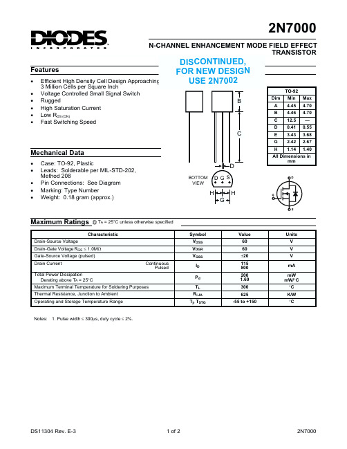
2N7000
N-CHANNEL ENHANCEMENT MODE FIELD EFFECT TRANSISTOR Features
· · · · · · Efficient High Density Cell Design Approaching 3 Million Cells per Square Inch Voltage Controlled Small Signal Switch Rugged High Saturation Current Low RDS (ON) Fast Switching Speed
D
BOTTOM VIEW
All Dimensions in mm
DG S
H
G
H
Maximum Ratings
Drain-Source Voltage
@ TA = 25°C unless otherwise specified Symbol VDSS VDGR VGSS Continuous Pulsed ID Pd TL RqJA Tj, TSTG Value 60 60 ±20 115 800 200 1.60 300 625 -55 to +150 Units V V V mA mW mW/°C °C K/W °C
DS11304 Rev. E-3
1 of 2
2N7000
元器件交易网
Electrical Characteristics @ TA = 25°C unless otherwise specified
Characteristics Drain-Source Breakdown Voltage Drain Cutoff Current Gate-Body Leakage Current Gate-Source Threshold Voltage Drain-Source On-Resistance Input Capacitance Output Capacitance Feedback Capacitance Turn-On Time Turn-Off Time Thermal Resistance, Junction to Ambient Symbol V(BR)DSS IDSS IGSS VGS(th) rDS(ON) CISS COSS CRSS ton toff RθJA Min 60 — — 0.8 — — — — — — — Typ — — — — — 60 25 5.0 10 10 — Max — 1.0 ±10 3.0 5.0 — — — — — 312.5 Unit V µA nA V W pF pF pF ns ns K/W Test Condition VGS = 0V, ID = 10µA VDS = 48V, VGS = 0V VGS = ±15V, VDS = 0V VDS = VGS, ID = 1.0mA VGS = 10V, ID = 0.5A
2060铝锂合金的淬透性

Volume29Number11The Chinese Journal of Nonferrous Metals November2019 DOI:10.19476/j.ysxb.1004.0609.2019.11.012060铝锂合金的淬透性刘晨1,李劲风1,2,宁红1,刘丹阳1,陈永来3,张绪虎3,马鹏程3,谭澄宇1(1.中南大学材料科学与工程学院,长沙410083;2.中南大学有色金属材料科学与工程教育部重点实验室,长沙410083;3.航天材料及工艺研究所,北京100076)摘要:利用新型的薄板叠层端淬法结合时效后强度变化,评价2060铝锂合金的淬透性,并采用扫描电子显微镜(SEM)、透射电子显微镜(TEM)、场发射透射电子显微镜(STEM)及能谱(EDS)对末端淬火并T8时效后的微观组织进行了分析。
结果表明:以抗拉强度下降5%作为淬透深度的判断依据,则2060铝锂合金的淬透深度约为15mm。
随着距淬火端距离的增大,抗拉强度依次降低直至稳定,但在距淬火端12~18mm的区间内,强度发生较明显变化。
端淬过程中析出的富Cu相降低了固溶体过饱和程度,阻碍后续时效过程中同一位置T1相(Al2CuLi)的析出和长大,导致合金抗拉强度逐渐减小。
关键词:2060铝锂合金;淬透性;强度;微观组织文章编号:1004-0609(2019)-11-2451-08中图分类号:TG146.2文献标志码:A新型铝锂合金因具有高比强度、高比刚度、减重效果明显等优点,是理想的航空航天结构材料[1−3]。
相比第一代和第二代铝锂合金,第三代铝锂合金具有更高的强韧性、热稳定性、耐损伤性和较好的耐蚀性,因此可作为为大型航空飞行器机身蒙皮和机翼壁板的新型结构材料[4−5]。
2060铝锂合金是2000年以后开发的第三代铝锂合金,目前已用于C919飞机蒙皮。
在成分设计上,2060铝锂合金提高了Cu、Li质量比,有利于促进主要强化相T1(Al2CuLi)相的析出[6]。
- 1、下载文档前请自行甄别文档内容的完整性,平台不提供额外的编辑、内容补充、找答案等附加服务。
- 2、"仅部分预览"的文档,不可在线预览部分如存在完整性等问题,可反馈申请退款(可完整预览的文档不适用该条件!)。
- 3、如文档侵犯您的权益,请联系客服反馈,我们会尽快为您处理(人工客服工作时间:9:00-18:30)。
VCE(sat) VBE(sat)
DYNAMIC CHARACTERISTICS
Common Emitter Small-Signal Short-Circuit Forward-Current Transfer ratio IC = 50 mAdc, VCE = 10 Vdc, f = 20 MHz Small-Signal Short-Circuit Input Impedance IC = 1.0 mAdc, VCB = 5.0 Vdc, f = 1.0 kHz Small-Signal Short-Circuit Forward-Current Transfer Ratio IC = 1.0 mAdc, VCE = 5.0 Vdc, f = 1.0 kHz Small-Signal Short-Circuit Input Impedance IC = 1.0 mAdc, VCE = 5.0 Vdc, f = 1.0 kHz Small-Signal Open-Circuit Output Admittance IC = 1.0 mAdc, VCE = 5.0 Vdc, f = 1.0 kHz Input Capacitance VEB = 0.5 Vdc, IE = 0, 100 kHz ≤ f ≤ 1.0 MHz Output Capacitance VCB = 10 Vdc, IE = 0, 100 kHz ≤ f ≤ 1.0 MHz (3)Pulse Test: Pulse Width 250 to 350µs, Duty Cycle ≤ 2.0%. hfe hib hfe hie hoe Cibo Cobo 3 20 50 1,000 0 25 30 150 4,000 16 85 15 Ω µmhos pF pF Ω
6 Lake Street, Lawrence, MA 01841 1-800-446-1158 / (978) 794-1666 / Fax: (978) 689-0803
120101 Page 2 of 2
IEBO
6 Lake Street, Lawrence, MA 01841 1-800-446-1158 / (978) 794-1666 / Fax: (978) 689-0803
120101 Page 1 of 2
元器件交易网
2N2060, 2N2060L JAN SERIES
mW W 0 C
TO-78*
*See appendix A for package outline
ELECTRICAL CHARACTERISTICS (TA = +250C unless otherwise noted)
Characteristics Symbol V(BR)CER V(BR)CEO ICBO Min. 80 60 10 2.0 10 2.0 Max. Unit Vdc Vdc µAdc Vdc mAdc
One Both Section Sections Total Power Dissipation @ TA = +250C (1) 540 600 PT @ TC = +250C (2) 1.5 2.12 Operating & Storage Junction Temperature Range -65 to +200 TJ, Tstg 0 0 0 1) Derate linearly 3.08 mW/ C for TA > 25 C for one section, 3.48 mW/ C for both sections 2) Derate linearly 8.6 mW/0C for TC > 250C for one section, 12.1 mW/0C for both sections
OFF CHARACTERISTICS
Collector-Emitter Breakdown Voltage(3) RBE ≤ 10 Ω, IC = 10 mAdc Collector-Emitter Breakdown Voltage IC = 30 mAdc Collector-Base Cutoff Current VCB = 100 Vdc VCB = 80 Vdc Emitter-Base Cutoff Current VEB = 7.0 Vdc VEB = 5.0 Vdc
MAXIMUM RATINGS Ratings
Collector-Emitter Voltage Collector-Base Voltage Emitter-Base Voltage Collector Current
Symbol
VCEO VCBO VEBO IC
2N2060
60 100 7.0 500
ELECTRICAL CHARACTERISTICS (con’t)
Characteristics Symbol Min. Max. Unit
ON CHARACTERISTICS (3)
Forward-Current Transfer Ratio IC = 10 µAdc, VCE = 5.0 Vdc IC = 100 µAdc, VCE = 5.0 Vdc IC = 1.0 mAdc, VCE = 5.0 Vdc IC = 10 mAdc, VCE = 5.0 Vdc Collector-Emitter Saturation Voltage IC = 50 mAdc, IB = 5.0 mAdc Base-Emitter Saturation Voltage IC = 50 mAdc, IB = 5.0 mAdc hFE 25 30 40 50 75 90 120 150 0.3 0.9 Vdc Vdc
元器件交易网
TECHNICAL DATA
UNITIZED DUAL NPN SILICON TRANSISTOR
Qualified per MIL-PRF-19500/270 Devices 2N2060 2N2060L Qualified Level JAN JANTX JANTXV
