JC-3166软件使用手册
Bulletin 160 SSC Remote Keypad FRN 1.x 用户手册说明书
Important User InformationSolid-State equipment has operational characteristics differing from those ofelectromechanical equipment. “Safety Guidelines for the Application, Installationand Maintenance of Solid-State Controls” (Publication SGI-1.1) describes someimportant differences between solid-state equipment and hard-wiredelectromechanical devices. Because of this difference, and also because of the widevariety of uses for solid-state equipment, all persons responsible for applying thisequipment must satisfy themselves that each intended application of this equipmentis acceptable.In no event will Rockwell Automation be responsible or liable for indirect orconsequential damages resulting from the use or application of this equipment.The examples and diagrams in this manual are included solely for illustrativepurposes. Because of the many variables and requirements associated with anyparticular installation, Rockwell Automation cannot assume responsibility orliability for actual use based on the examples and diagrams.No patent liability is assumed by Rockwell Automation with respect to use ofinformation, circuits, equipment, or software described in this manual.Reproduction of the contents of this manual, in whole or in part, without writtenpermission of Rockwell Automation is prohibited.Throughout this manual we use notes to make you aware of safety considerations:SSC is a trademark of Rockwell Automation, Inc.Table of Contents IntroductionDrive Compatibility . . . . . . . . . . . . . . . . . . . . . . . . . . . . . . . . . . . . . . . . . . . . . . . . . . . . . . . . . . . . . . .1-1Related Publications . . . . . . . . . . . . . . . . . . . . . . . . . . . . . . . . . . . . . . . . . . . . . . . . . . . . . . . . . . . . . .1-1Remote Programming Adapter . . . . . . . . . . . . . . . . . . . . . . . . . . . . . . . . . . . . . . . . . . . . . . . . . . . . . .1-2 Removal and Installation . . . . . . . . . . . . . . . . . . . . . . . . . . . . . . . . . . . . . . . . . . . . . . . . . . .1-2Grounding . . . . . . . . . . . . . . . . . . . . . . . . . . . . . . . . . . . . . . . . . . . . . . . . . . . . . . . . . . . . . .1-3 Connector Cable . . . . . . . . . . . . . . . . . . . . . . . . . . . . . . . . . . . . . . . . . . . . . . . . . . . . . . . . . . . . . . . . .1-4Features . . . . . . . . . . . . . . . . . . . . . . . . . . . . . . . . . . . . . . . . . . . . . . . . . . . . . . . . . . . . . . . . . . . . . . .1-5Display Description . . . . . . . . . . . . . . . . . . . . . . . . . . . . . . . . . . . . . . . . . . . . . . . . . . . . . . . . . . . . . . .1-6Drive Status Indicators . . . . . . . . . . . . . . . . . . . . . . . . . . . . . . . . . . . . . . . . . . . . . . . . . . . . . . . . . . . .1-6Keypad Initialization Sequence . . . . . . . . . . . . . . . . . . . . . . . . . . . . . . . . . . . . . . . . . . . . . . . . . . . . . .1-7 InstallationPrepare Mounting Location . . . . . . . . . . . . . . . . . . . . . . . . . . . . . . . . . . . . . . . . . . . . . . . . . . . . . . . . .2-1Mount the Remote Keypad . . . . . . . . . . . . . . . . . . . . . . . . . . . . . . . . . . . . . . . . . . . . . . . . . . . . . . . . .2-2 Control the DriveEnable Keypad Control to Start the Drive . . . . . . . . . . . . . . . . . . . . . . . . . . . . . . . . . . . . . . . . . . . . . .3-1Save Changes to Parameter 46 . . . . . . . . . . . . . . . . . . . . . . . . . . . . . . . . . . . . . . . . . . . . . . . . . . . . .3-1Stop the Drive . . . . . . . . . . . . . . . . . . . . . . . . . . . . . . . . . . . . . . . . . . . . . . . . . . . . . . . . . . . . . . . . . . .3-2Change Direction of Motor Rotation . . . . . . . . . . . . . . . . . . . . . . . . . . . . . . . . . . . . . . . . . . . . . . . . . .3-2 TroubleshootingHow to Clear a Fault . . . . . . . . . . . . . . . . . . . . . . . . . . . . . . . . . . . . . . . . . . . . . . . . . . . . . . . . . . . . . .4-1Resolving Problems . . . . . . . . . . . . . . . . . . . . . . . . . . . . . . . . . . . . . . . . . . . . . . . . . . . . . . . . . . . . . .4-2 Technical SpecificationsDimensions . . . . . . . . . . . . . . . . . . . . . . . . . . . . . . . . . . . . . . . . . . . . . . . . . . . . . . . . . . . . . . . . . . . . .A-1 Ambient Conditions . . . . . . . . . . . . . . . . . . . . . . . . . . . . . . . . . . . . . . . . . . . . . . . . . . . . . . . . . . . . . . .A-1 Input/Output Ratings . . . . . . . . . . . . . . . . . . . . . . . . . . . . . . . . . . . . . . . . . . . . . . . . . . . . . . . . . . . . . .A-1 Approvals and Standards Compliance . . . . . . . . . . . . . . . . . . . . . . . . . . . . . . . . . . . . . . . . . . . . . . . .A-1 Maintenance . . . . . . . . . . . . . . . . . . . . . . . . . . . . . . . . . . . . . . . . . . . . . . . . . . . . . . . . . . . . . . . . . . . .A-2iiChapter 1Introduction The Remote Keypad can be used to change drive parameter values, monitoroperating conditions, and control drive operation.Important:The four-character Remote Keypad display requires an extrakeystroke in order to display a current parameter value. See feature4 on page 1-5 and step 4 on page 3-1.Remote Keypad Figure 1.1Drive CompatibilityThe Remote Keypad is compatible with Bulletin 160 SSC™ Variable Speed SeriesC drives using firmware version FRN 7.01 or higher.Related PublicationsPrior to using the Remote Keypad, please familiarize yourself with the followingpublications for complete parameter and fault descriptions and detailedinformation about hazards associated with AC drives.•160 SSC™ Variable Speed Drive (Series C) User Manual,Publication 0160-5.15•160 SSC™ Variable Speed Drive Quick Reference Series C,Publication 0160-5.161-2IntroductionRemote Programming AdapterThe Remote Programming Adapter (160-RPA) allows the Remote Keypad tointerface with a Bulletin 160 Series C drive.If your drive is equiped with a Ready/Fault Indicating Panel (160-B1) or a ProgramKeypad Module (160-P1), you must remove these modules and install a RemoteProgramming Adapter in order to use the Remote Keypad.Removal and InstallationInsert a small screw driver into the slot at top of panel/keypad. Carefully pry backand pivot the module out. Avoid bending or twisting the contact pins locatedunderneath the center portion of the module.Insert the RPA module, bottom first, into the drive. Press down on the top cornersof the module until it is firmly seated.Module Removal and Adapter Installation Figure 1.2Introduction1-3 GroundingIt is required that the Remote Programming Adapter be earth grounded to improvenoise immunity and to guard the Remote Keypad against hazardous DC buspotential voltages.1-4IntroductionConnector CableA cable is used to connect the Remote Keypad to the Bulletin 160 Series C drive.The Keypad can be connected and disconnected when the drive is under power.Important:If P46 - [Input Mode] is set to 2 or 6, disconnecting the RemoteKeypad will cause the drive to fault.The following connector cables are available and purchased separately.•160-C10 – 1 meter cable, non-locking•160-C10R – 1 meter cable, non-locking with right angle for minimal depth•160-C30 – 3 meter cable, locking each end•160-C50 – 5 meter cable, locking each endThe 3- and 5-meter connector cables have a locking mechanism to ensure that thecable will not be disconnected accidentally. The 1-meter connector cables do nothave a locking mechanism. To remove the cable from the drive or the RemoteKeypad, pull back on the plastic housing of the cable connector.Introduction 1-5FeaturesThe figure and table below identify and describe the Remote Keypad display, status indicators, and keys.Remote Keypad Features Figure 1.6 FeatureDescription 1Display Four 7-segment light emitting diodes (LEDs)2Indicator LEDs Four LEDs indicate mode of operation.3Escape Key •Press to toggle between Display mode and Program mode.•In Edit mode, press to cancel an edit sequence and return to Programmode.4Enter Key •In Display or Program modes, press to toggle between parameter numbersand values.•In Edit mode, press to save a new parameter value.5Select Key In Program mode with a parameter value displayed, press to enter Edit mode.Use the Up or Down arrow keys to change the parameter value.6Up and Down Arrow Keys •In Program mode, use to scroll Program Group parameter numbers orchange a parameter value.•In Display mode, use to scroll Display Group parameters numbers.7Reverse Key Changes direction of motor rotation when keypad control is selected(P46 = 2 or 6) and reverse is enabled (P73 = 0)8Start Key Issues a start command to drive when keypad control is selected(P46 = 2 or 6).9Stop Key •Issues a stop command to drive.•Press to reset a fault after taking corrective action.1-6 IntroductionDisplay DescriptionThe keypad has a four-character LED display which shows parameter numbers, parameter values, and fault codes. The keypad monitors its connection to the drive. If this connection fails due to electrical noise or a hardware failure, the following is displayed.If the drive faults, the display will flash indicating the presence of the fault, and the fault code will be displayed. Pressing the Up or Down arrow, Enter, or Escape key will return the keypad to Display mode. If the fault condition is reset without pressing one of these keys, the display will return to the display or program parameter that was selected prior to the occurrence of the fault.Drive Status IndicatorsThe keypad has four status LEDs which serve as mode and direction indicators.LED FunctionsT able 1.B NameStatus DescriptionPROGRAM OnThe keypad is in Program mode.OffThe keypad is in Display mode.FlashingThe keypad is in Edit mode.RUNOn The drive is running.FORWARDOn If keypad control is selected (P46 = 2 or 6), this LED will turn onif the direction commanded by the keypad is forward.If keypad control is not selected, this LED will turn on when thedrive is running forward.Flashing The FORWARD LED will flash when the drive is commanded tochange direction from forward to reverse and will stop flashingwhen the motor decelerates to zero. The REVERSE LED willilluminate indicating the commanded direction.REVERSE On If keypad control is selected (P46 = 2 or 6), this LED will turn onif the direction commanded by the keypad is reverse.If keypad control is not selected, this LED will turn on when thedrive is running reverse.Flashing The REVERSE LED will flash when the drive is commanded tochange direction from reverse to forward and will stop flashingwhen the motor decelerates to zero. The FORWARD LED willilluminate indicating the commanded direction.Introduction1-7 Keypad Initialization SequenceWhen the Remote Keypad is connected to the drive, and power is applied, thefollowing is displayed for approximately two seconds.After two seconds have elapsed, the keypad will display the current value of thelast Display Group parameter selected. In this example, P01 - [Output Frequency] isat 0.0 Hertz.1-8Introduction End of ChapterChapter 2InstallationPrepare Mounting Location•Select a mounting location that is less than 5 meters away from the drive.Connection cables are available in 1, 3, and 5 meter lengths.•Install in a suitable IP55 or IP65 rated enclosure.Drilling Pattern and Dimensions Figure 2.12-2InstallationMount the Remote KeypadInstallation and T orque Sequence Figure 2.2Chapter 3Control the Drive Enable Keypad Control to Start the DriveThe following steps also serve as a programming example.1.With the Remote Keypad installed and connected to the Bulletin 160 Series Cdrive, power up the drive.The Remote Keypad always powers up in the Display mode. While in thismode you may view all read only drive parameters, but not modify them.2.Press the Escape key to enter the Program mode.The Program LED will light and Parameter 30 is displayed.e the Up or Down arrow key to scroll to P46 - [Input Mode].4.Press the Enter key to display the parameter value.5.Press the Select key to enter the Edit mode.The Program LED will flash indicating that the parameter value may bechanged.6.Change P46 - [Input Mode] to 2 or 6 using the Up or Down arrow key.7.Press the Enter key to save the new value.The Program LED will stop flashing and remain lit.Important:When P46 - [Input Mode] is set to 2 or 6, disconnecting the RemoteKeypad will cause the drive to fault.Save Changes to Parameter 46In order for changes to P46 - [Input Mode] to take effect, cycle power or setP56 - [Reset Functions] to 2.e the Up or Down arrow key to scroll to P56 - [Reset Functions].2.Press the Enter key to display the default parameter value of 0.3.Press the Select key to enter the Edit mode.4.Change P56 - [Reset Functions] to 2 using the Up or Down arrow key.5.Press the Enter key to save the new value.The new P46 - [Input Mode] value is saved and P56 - [Reset Functions] resets to 0.You can now use the Remote Keypad to start the drive.Important:The Stop/Reset digital input on the drive (TB3-8) must bemaintained in the ON state for the keypad to start the drive.3-2Control the DriveStop the DriveUse the Stop key to command the drive to stop. The Stop key functions in all driveinput modes whether or not the keypad is selected as the drive’s control source.Change Direction of Motor RotationOnce the Remote Keypad is set to control drive operation (P46 - [Input Mode] is setto 2 or 6) you can change the direction of motor rotation by pressing the Reverse key.When the motor is running, pressing the Reverse key causes the motor to rampdown to 0 Hz and then ramp up to its set speed in the opposite direction.Chapter 4TroubleshootingHow to Clear a FaultWhen a fault occurs, the cause must be corrected before the fault can be cleared.After corrective action has been taken, any of the following actions will clear thefault.•Press the Remote Keypad Stop button•Set P54 - [Clear Fault] to 1.•Disconnect power to the drive, wait three minutes, reapply power.•Cycle the input signal at TB3-8 to the drive.Please consult the 160 SSC™ Variable Speed Drive (Series C) User Manual,Publication 0160-5.15, for a complete listing of fault descriptions and possibleproblems and corrective actions.4-2Troubleshooting DRAFT – 7/19/99 Resolving ProblemsImportant:The connector cable, RPA, and Keypad are not repairable.Appendix ATechnical Specifications DimensionsAmbient Conditions•Operating temperature: 0˚ C to 50˚ C (32˚ F to 122˚ F)•Storage temperature: -40˚ C to 85˚ C (-40˚ F to 185˚ F)•Relative humidity: 0 to 95%, non-condensing.Input/Output Ratings•Input voltage: 5 VDC (from drive power supply)•Input current: 75 mA (maximum, from drive power supply)Approvals and Standards Compliance•UL508C•CSA 22.2•CE•EN-50178•IP 66 (NEMA Type 12/UL Type 4X Indoor)A-2Technical SpecificationsMaintenanceUse only a soft cloth dampened with water to clean the keypad.The RPA requires no maintenance or cleaning.Publication 0160-5.28ML – September, 1999P/N 194308 (01)Copyright 1999 Rockwell International Corporation. All rights reserved. Printed in USA.。
三核监视器的用户手册说明书

T riCore Monitor Release 09.2023TRACE32 Online HelpTRACE32 DirectoryTRACE32 IndexTRACE32 Documents ...................................................................................................................... ICD In-Circuit Debugger ................................................................................................................ Processor Architecture Manuals .............................................................................................. TriCore ...................................................................................................................................... TriCore Monitor .. (1)Introduction (4)Brief Overview of Documents for New Users4 Quick Start of the TriCore Serial Monitor (5)Troubleshooting (6)FAQ (6)Basics (7)Monitor Features7General SYStem Settings and Restrictions (8)SYStem.CPU CPU type8 SYStem.CpuAccess Run-time memory access (intrusive)8 SYStem.Down Disables monitor9 SYStem.MemAccess Real-time memory access (non-intrusive)9 SYStem.Mode Establish the communication with the CPU10 SYStem.Option.IMASKASM Disable interrupts while single stepping11 SYStem.Option.IMASKHLL Disable interrupts while HLL single stepping11TrOnchip (12)TrOnchip.CONVert Adjust range breakpoint in on-chip resource12 TrOnchip.VarCONVert Adjust complex breakpoint in on-chip resource12 TrOnchip.RESet Set on-chip trigger to default state13 TrOnchip.TEnable Set filter for the trace13 TrOnchip.TOFF Switch the sampling to the trace to OFF13 TrOnchip.TON Switch the sampling to the trace to “ON”13Memory Classes (14)Version 10-Oct-2023IntroductionThis document describes the processor specific settings and features of the T riCore ROM Monitor. Y ou can find the description of the OCDS-L1 Debugger for the T riCore family at “TriCore Debugger and Trace”(debugger_tricore.pdf).Please keep in mind that only the Processor Architecture Manual (the document you are reading at the moment) is CPU specific, while all other parts of the online help are generic for all CPUs supported by Lauterbach. So if there are questions related to the CPU, the Processor Architecture Manual should be your first choice.Brief Overview of Documents for New UsersArchitecture-independent information:•“Training Basic Debugging” (training_debugger.pdf): Get familiar with the basic features of a TRACE32 debugger.•“T32Start” (app_t32start.pdf): T32Start assists you in starting TRACE32 PowerView instances for different configurations of the debugger. T32Start is only available for Windows.•“General Commands” (general_ref_<x>.pdf): Alphabetic list of debug commands.Architecture-specific information:•“Processor Architecture Manuals”: These manuals describe commands that are specific for the processor architecture supported by your Debug Cable. T o access the manual for your processorarchitecture, proceed as follows:-Choose Help menu > Processor Architecture Manual.•“OS Awareness Manuals” (rtos_<os>.pdf): TRACE32 PowerView can be extended for operating system-aware debugging. The appropriate OS Awareness manual informs you how to enable theOS-aware debugging.Quick Start of the TriCore Serial MonitorStarting up the ROM Monitor is done as follows:6.Select the device B: for the ROM Monitor.7.Transition to the down mode before pressing the reset button.This instruction is necessary when the system is restarted.8.Set the CPU type in the ROM Monitor program:9.Define the communication parameters.10.Activate the ROM monitorA typical start sequence is shown below:The start-up can be automated using the programming language PRACTICE.B:SYStem.Mode DownSYStem.CPU TC1796SYStem.PORT COM2 BAUD=38400SYStem.Up; for this example the TriBoard TC1796 Evaluation board is used B:SYStem.Mode Down WinCLREARSYStem.CPU tc1796 SYStem.PPORT COM2 BAUD=38400; select the Debugger device ; switch the system down ; clear all windows; set the CPU type for the user interfaceSYStem.Mode UpTroubleshooting No information available. FAQNo information availableBasicsMonitor FeaturesThe monitor requires no stack.General SYStem Settings and RestrictionsSYStem.CPU CPU type Format:SYStem.CPU <cpu><cpu>:TC1792 | TC1796 | TC1796EDSelects the processor type. The ROM debugger requires also a modification in the debug monitor fordifferent processor types.SYStem.CpuAccess Run-time memory access (intrusive) Format:SYStem.CpuAccess Enable | Denied | NonstopDefault: Denied.Enable Allows intrusive run-time memory access.In order to perform a memory read or write while the CPU is executingthe program, the debugger stops the program execution shortly. Eachshort stop takes 1…100ms depending on the speed of the debuginterface and on the number of the read/write accesses required.A white S against a red background in the state line of the TRACE32 mainwindow indicates this intrusive behavior of the debugger.Denied Locks intrusive run-time memory access.Nonstop Locks all features of the debugger that affect the run-time behavior.Nonstop reduces the functionality of the debugger to:•Run-time access to memory and variables•Trace displayThe debugger inhibits the following:•To stop the program execution•All features of the debugger that are intrusive (e.g. action Spot forbreakpoints, performance analysis via StopAndGo mode, condi-tional breakpoints, etc.)SYStem.Down Disables monitor Format:SYStem.DownSYStem.MemAccess Real-time memory access (non-intrusive) Format:SYStem.MemAccess Enable | StopAndGo | Denied | NEXUS |<cpu_specific>SYStem.ACCESS (deprecated)Real-time memory access during program execution to target is enabled.EnableCPU (deprecated)Denied (default)Real-time memory access during program execution to target is disabled.StopAndGo Temporarily halts the core(s) to perform the memory access. Each stoptakes some time depending on the speed of the JT AG port, the number ofthe assigned cores, and the operations that should be performed.For more information, see below.NEXUS Memory access is done via the NEXUS interface.SYStem.Mode Establish the communication with the CPU Format:SYStem.Mode <mode><mode>:DownNoDebugGoUpDefault: Down. Selects the target operating mode.Down The CPU is in reset. Debug mode is not active. Default state and state after fatalerrors.NoDebug The CPU is running. Debug mode is not active. Debug port is tristate. In thismode the target should behave as if the debugger is not connected.Go The CPU is running. Debug mode is active. After this command the CPU can bestopped with the break command or if any break condition occurs.Up The CPU is not in reset but halted. Debug mode is active. In this mode the CPUcan be started and stopped. This is the most typical way to activate debugging.If the mode “Go” is selected, this mode will be entered, but the control button in the SYStem window jumps to the mode “UP”.SYStem.Option.IMASKASM Disable interrupts while single stepping Format:SYStem.Option.IMASKASM [ON | OFF]Default: OFF.If enabled, the interrupt mask bits of the CPU will be set during assembler single-step operations. The interrupt routine is not executed during single-step operations. After single step the interrupt mask bits are restored to the value before the step.SYStem.Option.IMASKHLL Disable interrupts while HLL single stepping Format:SYStem.Option.IMASKHLL [ON | OFF]Default: OFF.If enabled, the interrupt mask bits of the CPU will be set during HLL single-step operations. The interrupt routine is not executed during single-step operations. After single step the interrupt mask bits are restored to the value before the step.TrOnchipTrOnchip.CONVertAdjust range breakpoint in on-chip resource The on-chip breakpoints can only cover specific ranges. If a range cannot be programmed into thebreakpoint, it will automatically be converted into a single address breakpoint when this option is active. This is the default. Otherwise an error message is generated.TrOnchip.VarCONVertAdjust complex breakpoint in on-chip resource The on-chip breakpoints can only cover specific ranges. If you want to set a marker or breakpoint to a complex variable, the on-chip break resources of the CPU may be not powerful enough to cover the whole structure. If the option TrOnchip.VarCONVert is set to ON , the breakpoint will automatically be converted into a single address breakpoint. This is the default setting. Otherwise an error message is generated. Format:TrOnchip.CONVert [ON | OFF ] (deprecated)Use Break.CONFIG.InexactAddress insteadTrOnchip.CONVert ONBreak.Set 0x1000--0x17ff /WriteBreak.Set 0x1001--0x17ff /Write…TrOnchip.CONVert OFFBreak.Set 0x1000--0x17ff /WriteBreak.Set 0x1001--0x17ff /Write ; sets breakpoint at range ; 1000--17ff sets single breakpoint ; at address 1001; sets breakpoint at range ; 1000--17ff ; gives an error messageFormat:TrOnchip.VarCONVert [ON | OFF ] (deprecated)Use Break.CONFIG.VarConvert insteadTrOnchip.RESet Set on-chip trigger to default state Format:TrOnchip.RESetSets the T rOnchip settings and trigger module to the default settings.TrOnchip.TEnable Set filter for the trace Format:TrOnchip.TEnable <par> (deprecated)Refer to the Break.Set command to set trace filters.TrOnchip.TOFF Switch the sampling to the trace to OFF Format:TrOnchip.TOFF (deprecated)Refer to the Break.Set command to set trace filters.TrOnchip.TON Switch the sampling to the trace to “ON”Format:TrOnchip.TON EXT | Break (deprecated)Refer to the Break.Set command to set trace filters.Memory ClassesMemory Class DescriptionD DataP ProgramC Memory access by CPUE Emulation memory accessA Absolute (physical) memory access。
CAT-316-DA 3 16 PRO. 6 随机轨道掌型沙子说明书
This Instruction Manual Contains Important Safety Information.Read THIS INSTRUCTIONMANUAL Carefully andunderstand ALL INFORMATIONBefore Operating THIS Tool.• Always operate, inspect and maintain this tool in accordance withAmerican National Standards InstituteSafety Code of Portable Air Tools (ANSIB186.1) and any other applicable safetycodes and regulations.•For safety, top performance and maximum durability of parts, operate this tool at 90psig 6.2 bar max air pressure with 3/8"diameter air supply hose.• Always wear impact-resistanteye and face protection whenoperating or performingmaintenance on this tool.Always wear hearing protectionwhen using this tool.• High sound levels can causepermanent hearing loss. Usehearing protection asrecommended by your employeror OSHA regulation.•Keep the tool in efficient operatingcondition.•Operators and maintenance personnel must be physically able to handle the bulk, weight and power of this tool.• Air under pressure can causesevere injury. Never direct air atyourself or others. Always turnoff the air supply, drain hose ofair pressure and detach toolfrom air supply before installing, removing or adjusting any accessory onthis tool, or before performing anymaintenance on this tool. Failure to do socould result in injury. Whip hoses cancause serious injury. Always check fordamaged, frayed or loose hoses andfittings, and replace immediately. Do notuse quick detach couplings at tool. Seeinstructions for correct set-up.• Air powered tools can vibratein use. Vibration, repetitivemotions or uncomfortablepositions over extended periodsof time may be harmful to yourhands and arms. Discontinue use of tool if discomfort, tingling feeling or pain occurs. Seek medical advice beforeresuming use.•Place the tool on the work before starting the tool.• Slipping, tripping and/or fallingwhile operating air tools can bea major cause of serious injury ordeath. Be aware of excess hoseleft on the walking or worksurface.•Keep body working stance balanced and firm. Do not overreach when operating the tool.•Anticipate and be alert for sudden changes in motion during start up and operation ofany power tool.• Do not carry tool by the hose.Protect the hose from sharpobjects and heat.•Do not lubricate tools with flammable or volatile liquids such as kerosene, diesel or jet fuel.•Don't force tool beyond its rated capacity.•Do not remove any labels. Replace any damaged labels.WARNING!FAILURE TO OBSERVE THESE WARNINGS COULD RESULT IN INJURY CAT-316-DA_man-010704.q 1/8/04 12:36 PM Page 210111213141515A 1617111111111111111511Qty.11113111111111112(Optional)Qty.Ref. #RS31601RS47502RS47503RS47504RS47505RS47506RS47507RS47508RS31609RS47510RS10920RS47512RS47513RS47514RS47515RS47515A RS47516RS47517Description Lever Pin Muffler Muffler Body Inlet Bushing Spring Valve Seat Housing Ring Bearing Rear End Plate Cylinder Assy.O-Ring Rotor Rotor Blade Ring Control Description O-Ring Stem Key Front End Plate Bearing O-Ring Lock Ring Shaft Balancer--3/16" Orbit Shim Washer Ring Spindle 6" TE NV Vinyl Face Pad Pad Wrench O-Ring Plate Screw Vacuum Conversion Kit 6" TE NV Hook Face Pad6" TE Vacuum Hook Face PadPart #Ref. #Part #RS47518RS47519RS47520RS47521RS227B25RS47523RS47524RS47525RS47527RS47529RS47530RS47531CAT-6NV-PAD RS47533RS47534RS47535RS47536CAT-4126CAT-6NVH-PAD CAT-6VH-PAD 1819202122232425272930313233343536Also available:。
铯源塞棒软件说明书(最新版)
红色
驱动器故障 故障指示 指示驱动器发生故障
红色
塞棒已关闭
状态指示
指示电动缸已处于关 闭到行程极限位
红色
ቤተ መጻሕፍቲ ባይዱ
20
$#k
4.2.2 修改参数
单击主控台上“修改参数”按钮,在进入“修改参数”窗口 对断面参数进行修改之前,STOPCON 会弹出对话框要求用户 输入用户名和密码。
如下图所示:
出厂时默认的用户名和密码分别是 Ramon 和 8857723。此用 户名和密码是不能够删除的。进入“修改参数”窗口后,用户 可以自行增加新用户和修改密码。
打开 WindowsNT4.0 桌面上的“.我.的.电.脑.”.→ “.控.制.面.板.”.→ “.显.示.”.,.出现“.显.示.属.性.”.窗口。如下图所示:
3.2 “显示属性”设置
单击“.显.示.属.性.”.窗体中的设置页,在“.颜.色.栏.”.中选择 True Color,在屏幕区域栏中移动滑块,直至滑块下显示 1024×768 象素。 在“.字.体.大.小.”.栏中选择小字体选项,单击“.确.认.”.按钮关闭本窗体,
★ 单击 STOPCON 界面左上角的联机按钮后,按钮上的文字由“联 机”变成了“脱机”,按钮上灯的颜色也由红.色.变成了绿.色.,同时状 态栏上的进度条开始了不断的刷新,表示目前上位机正处于和 PLC 联机状态。
★ 第一次运行 STOPCON 界面程序,由于用户还没有创建自定义 断面,系统使用默认的断面,断面中所有的参数均为预设值,用户不
15
★. 曲.线.放.大.功.能.
STOPCON 界面软件可以任意选取一段时间内的曲线,将其放 大来观察它的细微变化。 如下图所示:
具体操作方法如下: 放大的步骤: 1、 在趋势图中按下鼠标左键不放,同时向趋势图的右下角
Nova M3系列控制系统用户手册-V4.9.0 - 副本

系统用户手册LED显示屏控制系统M3Rev4.9.0NS110000230声明尊敬的用户:欢迎您成为Nova M3系列控制系统的使用者,如果本手册为您了解和使用产品带来帮助和便利,我们深感欣慰,我们在编写手册时力求精确可靠,诺瓦会在未通知的情况下随时对手册的内容进行修改和变更,如果您在使用中遇到任何使用问题,或者您有好的建议,请按照手册提供的来联系方式联系我们,对您在使用中遇到的问题,我们会尽力给予支持,对您提出的建议,我们衷心感谢并尽快评估采纳。
版权本手册版权归西安诺瓦科技所有,任何个人或单位未经书面许可,不得以任何形式对文本内容作复制、摘录。
商标是诺瓦科技的注册商标文档标识符定义注意ATTENTION: Identifies information that requires special consideration.提示:标记对用户的建议或提示。
TIP:Identifies advice or hints for the user.目录1系统概述 (1)1.1配置列表 (1)1.2系统架构 (2)2工作环境要求 (3)3 NovaLCT-Mars的安装 (4)4 NovaLCT-Mars介绍 (5)4.1高级用户界面 (5)4.2修改密码 (6)4.3菜单/工具栏 (7)5主要功能说明 (9)5.1点亮显示屏 (9)5.1.1使用系统配置文件点亮显示屏 (9)5.1.2通过手动配置点亮显示屏 (10)5.1.3设置箱体信息 (26)5.1.4性能参数的调整 (27)5.1.5分辨率及刷新率的调整 (36)5.1.6 3D配置 (37)5.1.7接收卡冗余设置 (38)5.1.8输入源设置 (40)5.1.9源配置 (40)5.1.10参数固化 (41)5.1.11配置文件保存和加载 (41)5.2高级颜色配置 (45)5.3亮度,Gamma及电流增益设置 (50)5.3.1手动调节 (52)5.3.2自动调节 (53)5.4画面控制 (63)5.5获取硬件版本信息 (64)5.6多个显示屏管理 (66)5.7监控硬件状态 (68)5.7.1设置刷新周期 (69)5.7.2硬件配置 (70)5.7.3数据告警配置 (73)5.7.4监控配置 (74)5.7.5邮件配置 (76)5.7.6邮件日志 (77)5.8显示屏的灯点(点检) (78)5.9显示屏校正 (80)5.9.1联机校正 (80)5.9.2系数管理 (81)5.9.3双校正系数 (99)5.10多功能卡管理 (100)5.10.1多功能卡的配置 (101)5.10.2电源管理 (101)5.10.3数据监控 (105)5.10.4外设管理 (106)5.10.5程序加载 (106)5.10.6音频管理 (108)5.11预存画面 (109)6灯板Flash (111)7多批次调节 (114)7.1手动调节 (114)7.2使用文件调节 (123)8接收卡继电器 (125)9控制器箱体配置文件导入 (126)10配置信息管理 (131)11硬件程序升级 (132)12快速调节亮暗线 (134)12.1调节亮暗线 (134)12.2还原亮暗线 (139)13视频控制 (141)14灯板ID设置 (145)15云监控 (147)16常见问题排除 (149)16.1软件上显示No Hardware (149)16.2软件上显示“无屏体信息” (149)16.3智能设置时显示屏显示错误 (150)16.4智能设置时每个箱子只有部分灯板显示正常智能设置 (151)16.5权限错误 (151)16.6旧版本安装失败 (160)17附录 (161)17.1更新说明 (161)1 系统概述Nova M3系列LED显示屏控制系统,以软件NovaLCT-Mars为操作平台,配合数据收发卡、监控卡以及多功能卡,实现对LED显示屏的智能设置、亮度调节、电源控制、灯点监测、屏体校正和硬件监控,用户在计算机前就能轻松控制显示屏的所有关键信息,使您的显示屏时刻完美展现。
MODEL 3165 3166 使用说明说明书
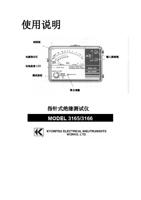
使用说明指针式绝缘测试仪刻度板电源指示灯电池检查LED测试按钮零点调整输入接线端1.安全警告●本使用说明书包含警告信息及安全规定,使用时请严格遵守,以确保使用者的操作安全及仪器安全,因此使用前请先仔细阅读。
●标志“”表示安全警告,为保证操作安全,建议操作者必须参考说明书中的相关细节内容,仔细阅读“”标志的内容。
●请注意说明书中所有警告和注意。
警告表示会对操作者造成触电的注意事项,注意表示会对仪器造成损坏的注意事项。
1. 请确认测试导线完全插入仪器的接线端。
2. 测量时请勿超过测量范围的最大允许输入。
3. 请确认仪器和接地的接线端间施加电压不超过600V AC/DC。
4. 请勿在易爆炸性气体的环境中测量(例如可燃气体或烟)。
5. 使用前认真检查测试导线和附件是否存在损坏或异常。
若存在异常现象(例如:测试导线损坏,仪器机身损坏),请勿进行测试。
6. 测试导线连接时请勿按下测试开关。
7. 绝缘测试时请勿触摸电路。
8. 打开电池盖更换电池前请取下测试导线,关闭仪器电源。
9. 使用后请关闭仪器电源。
10. 请勿将仪器暴露于直射太阳,潮湿或高温环境中。
11. 请勿将仪器存放于50℃以上的温度条件下。
12. 仪器的校正和修理应该由受过正规训练、合格的技术人员进行操作。
13. 不要使用其它的附件,如仪器出现故障不要由非受过正规训练人员进行修理,应将仪器返回至你的经销商由正规人员进行修理。
14. 本仪器必须由受过正规训练的、合格的技术人员进行操作,并在本说明书规定的条件下使用。
由于用户使用不当、或违反本说明书以及安全操作规定造成的设备损坏,共立公司(KYORITSU)将不负责任何责任。
2.特点●交流电压测量能被做没有沉闷测试钮扣。
●电池检查设备。
●仅使用R6(AA)(1.5V)×4电池类型3.规格●测量范围精确度(在23±5℃, 相对湿度45~75%)绝缘电阻范围:MODEL3165MODEL3166测试电压500V1000V测量范围1000MΩ2000MΩ中刻度值20MΩ50MΩ输出电压额定测试电压+20%-0%输出短路电流230μA最大450μA最大1-500MΩ:读数的±5%2-1000MΩ:读数的±5%精确性其他测试范围刻度的±0.7%交流电压警告警告范围0-600V交流精确性刻度的±3%电源 1.5V×4 (R6)(SUM-3)(AA)或等量电量。
DHT-S316 家庭影音系统使用指南说明书
DHT-S316HOME THEATER SYSTEM Owner’s ManualAccessories4 Inserting the batteries5 Operating range of the remote control unit5 Features6 Part names and functions7 Sound bar7 Subwoofer10 Remote control unit11 ConnectionsPositioning12 Positioning the sound bar12 Positioning the subwoofer14 Connecting a TV15 Connection 1: TV equipped with an HDMI connector and compatible with the ARC (Audio Return Channel)16 Connection 2: TV equipped with an HDMI connector and incompatible with the ARC / TV equipped with an optical digital connector17 Connection 3: TV equipped with an HDMI connector and incompatible with the ARC / TV equipped with an analog connector18 Connecting the power cords19PlaybackEnjoying television, movies and music20 Status LED table21 Listening to music on a Bluetooth device22 Pairing a Bluetooth device for the first time22 Pairing with other Bluetooth devices23 Listening to music with a paired Bluetooth device23 SettingsSettings24 Adjusting the volume24 Adjusting the subwoofer volume24 Selecting a listening mode25 Turning off the sound temporarily25 Setting the Bluetooth standby function25 Auto standby function26 Volume limiter function26TipsTroubleshooting27 Power does not turn on / Power is turned off28 Operations cannot be performed through the remote control unit28 No sound comes out29 Bluetooth playback does not work30 The HDMI Control function does not work30 Resetting factory settings31 AppendixAbout HDMI32 Trademark information33 Specifications34 Sound bar34 Subwoofer37Thank you for purchasing this Denon product.To ensure proper operation, please read this owner’s manual carefully before using the product. After reading this manual, be sure to keep it for future reference. AccessoriesCheck that the following parts are supplied with the product.Inserting the batteries1Slide the rear cover off the remote control unit in the2Insert 1 battery into the battery compartment as indicated.3Put the rear cover back on.NOTE0Remove the batteries from the remote control unit if it will not be in use for long periods.0If the battery fluid should leak, carefully wipe the fluid off the inside of the battery compartment and insert new batteries.Operating range of the remote control unitPoint the remote control unit at the remote sensor when operating it.0Two-way sound bar with wireless subwoofer: Powerful, dynamic Denon home theater soundEasy Setup: Quickly connect to your TV with the supplied HDMI or Optical cables.Wireless Subwoofer: Powerful bass without the cables. Place the subwoofer within 30 ft of the sound bar for optimal enjoyment.2" Low-profile Design: At 2" tall, the Denon DHT-S316 fits most spaces and can be placed in front of your TV without blocking your TV's bottom edge or IR remote sensor.0Exceptional sound clarity for your TV, Blu-ray, gaming system and favorite music sourcesHDMI with Audio Return Channel: Send audio from your TV’s built-in apps, on-board tuner or HDMI connections over a single cable when you connect your TV’s HDMI ARC output to the sound bar using the included HDMI cable.Digital Audio Optical Input: Effortlessly connect your Blu-ray, gaming or other device with the included Optical cable.Analog Auxiliary Input: Connect any source compatible with a 3.5 mm input and listen through the DHT-S316.Bluetooth: Connect your smartphone or tablet to the DHT-S316 to wirelessly stream music and other audio.0Immerse yourself in a realistic home theater experienceDolby Digital and DTS Decoding: Virtual surround technology creates a powerful, realistic multi-channel home theater experience.Denon Dialogue Enhancer: Never miss a word of your favorite TV show or movie, Denon Dialogue Enhancer improves dialogue intelligibility - ideal for movies and TV shows. Turn up the dialogue without having to adjust overall volume.Sound baro Top panelA Power operation button (c )Turns the sound bar power on/off (standby). (v p. 20)Links to sound bar power and turns the subwoofer power on/off (standby).B Input source button (d )This selects the input source. (v p. 20)Switches the input source each time the button is pressed.C Bluetooth button (g )0Switches the input source to “Bluetooth”. (v p. 22)0Used to pair with Bluetooth devices. (v p. 22)D Volume buttons (+, –)These adjusts the volume level. (v p. 24)o Front panelA Status LEDDisplays the status of input source / input signal / listening mode, etc. (v p. 21)B Remote control sensorThis receives signals from the remote control unit. (v p. 5)o Bottom panelqA USB portService terminal. Not used in normal operation.o Rear panelA Wall hook holeUsed to mount the sound bar on a wall. (v p. 13)B HDMI connector (TV (ARC))Use the included HDMI cable to connect an ARC function-compatible TV. (v p. 16)C AUX audio input connectorUse a commercially available 3.5 mm stereo audio cable to connect an audio device. (v p. 18)D Optical digital input connector (TV OPTICAL)Use the included optical digital cable to a TV with an optical digital terminal. (v p. 17)E AC inletUsed to connect the power cord. (v p. 19)Subwoofero Rear panelA Status LEDDisplays subwoofer status.0The sound bar and subwoofer are wirelessly connected as the factory default.If no audio is output from the subwoofer, wirelessly connect the sound barand subwoofer again. (v p. 29)B BAR SYNC buttonUsed to wirelessly connect the sound bar and subwoofer. (v p. 29)C AC inletUsed to connect the power cord. (v p. 19)q weRemote control unitThis section mainly explains remote control operations.A Power button (c )Turns the sound bar power on/off. (v p. 20)Links to sound bar power and turns the subwoofer power on/off.B Input source buttons (TV, AUX, g )This selects the input source. (v p. 20)C Button to adjust subwoofer (BASS +, -)Adjusts the volume level for the subwoofer. (v p. 24)D Night mode button (NIGHT)Compresses the dynamic range (difference between loud and soft sounds) to make audio easier to hear at low volumes. (v p. 25)E Movie mode button (MOVIE)Enjoy movie theater-like surround sound. (v p. 25)F Mute button (h )This mutes the output audio. Press again to unmute. (v p. 25)G Volume buttons (VOL +, –)These adjusts the volume level. (v p. 24)H Music mode button (MUSIC)Enjoy the full presence of a wide, encompassing acoustic field. (v p. 25)I Dialog enhancer buttons (DIALOG ENHANCER 1 - 3)Adjust the volume of dialog in movies, vocals in music, etc. so these can be heard more easily. (v p. 25)Can be set to 3 levels. Set this to the desired value.NOTE0When positioning the sound bar in front of your TV, make sure the sound bar does not obstruct the TV’s remote control light sensor, etc.o When hanging the sound bar on a wallThe sound bar has a wall hook hole to hang it on a wall. When hangingit on a wall, position it in a flat, vertical position.0When hanging it on a wall, use the included wall mount template.[How to use the wall mount template]A Affix the template to the location you would like to mount the sound bar.B Screw in the wall mount screws by following the template.Consult a construction professional about the proper wall mount screws forthe material and strength of your wall.C Remove the template from the wall.D Mount the included wall mount spacer on the spine of the sound bar.Mounting the wall mount spacer creates a space for cords to pass throughbetween the sound bar and the wall.E Mount the sound bar on the wall.NOTE0To ensure safety, request a contractor perform the mounting work when mounting onto a wall.0In order to use the unit safely, do not place items on or hang items from the unit.0Be sure to fix connection cables to the wall to ensure that cannot be pulled or tripped over causing this unit to fall. Check that the unit is mounted safely after the mounting work is complete.0Also, periodically check the safety of this unit and whether there is a possibility that the unit may fall.0Denon cannot accept any responsibility for damage, injury or accidents caused by problems with the mounting location or mounting method.Positioning the subwoofer Position the subwoofer in a flat location near the sound bar.How to connect a TV depends on the connectors and functions equipped on the TV.0Enable the TV’s HDMI control function when using an HDMI cable to connect this device to your TV. (See the TV Owner’s Manual for details.) 0Turn off the TV’s speaker or minimize the volume when using this device.0HDMI cable connection is recommended, but connection can be performed without an HDMI cable.NOTE0Make sure all devices are off when connecting.0Do not plug device power cords into an outlet until all devices have been connected.Connection 1: TV equipped with an HDMI connector and compatible with the ARC (Audio Return Channel)Use the included HDMI cable to connect this device to an ARC function-compatible TV.HDMI cable (included)0The TV also needs to be compatible with the ARC function.Connection 2: TV equipped with an HDMI connector and incompatible with the ARC / TV equipped with an optical digital connectorUse the included HDMI and optical digital cables to connect this device to your TV.HDMI cable (included)0Line up the optical digital cable with the shape of the terminal to insert.Connection 3: TV equipped with an HDMI connector and incompatible with the ARC / TV equipped with an analog connectorUse the included HDMI cable and a commercially available 3.5 mm stereo audio cable to connect this device to your TV.HDMI cable (included)After completing all the connections, insert the power plug into the power outlet.Connect to household power outlet(AC 120 V, 60 Hz)X buttons 1Turn on the power of the TV and connected devices. 2Press c to turn on power to the unit.3Press the input source button.4Play the device connected to this unit.For details, see the relevant device manual.0Connect an HDMI control-compatible TV and this device via HDMI and enable the HDMI control to enable linked control from either device. (v p. 32)Status LED tableStatus LEDs change depending on the input source, input signal, etc.0Audio signal is not displayed when the input source is “Bluetooth”.Music files stored on Bluetooth devices such as smartphones, digital music players, etc. can be enjoyed on this unit by pairing and connecting this unit with the Bluetooth device.XPairing a Bluetooth device for the first timePair a Bluetooth device with this unit.Once the Bluetooth device has been paired, it does not need to be paired again.1Press c to turn on power to the unit.2Press g to switch the input source to “Bluetooth”. 3Activate the Bluetooth settings on your Bluetooth device.Switches to pairing mode the first time it is used.4Select “DHT-S316” from the list of devices displayed on the screen of the Bluetooth device.Status display LED lights up in blue and this device and theBluetooth device are paired.0Pairing is canceled if the power cord is removed. Perform pairing again.Pairing with other Bluetooth devices 1Press c to turn on power to the unit.2Press g to switch the input source to “Bluetooth”. 3Activate the Bluetooth settings on your Bluetooth device.4Push g on this device until the status display LED blinks in blue.5Select “DHT-S316” from the list of devices displayed on the screen of the Bluetooth device.Status display LED lights up in blue and this device and theBluetooth device are paired.0This unit can be paired with a maximum of 8 Bluetooth devices. When a 9th Bluetooth device is paired, it will be registered in place of the oldest registered device.0Pairing is canceled if the power cord is removed. Perform pairing again.Listening to music with a paired Bluetooth device1Press c to turn on power to the unit.2Press g to switch the input source to “Bluetooth”. 3Activate the Bluetooth settings on your Bluetooth device.4Press g.The status display LED lights up in blue and connects to the last Bluetooth device connected. If the connection is cut, performconnection again.5Play music using any app on your Bluetooth device.Perform the below operations and settings as needed.BASS+, –Adjusting the volume1Use VOL + or VOL – to adjust the volume.The selected input source LED blinks once every time the button ispushed.Adjusting the subwoofer volume1Use BASS + or BASS – to adjust the subwoofer volume.The selected input source LED blinks once every time the button ispushed.Selecting a listening mode1Press the listening mode button to select a listening mode.The status display LED blinks once in purple.Turning off the sound temporarily1Press h.The selected input source LED blinks.0To cancel, press h again.Setting the Bluetooth standby function If Bluetooth standby function is set to “on”, this device automatically turns on when Bluetooth connects via the paired Bluetooth device.In order to use this operation, the device needs to be paired with this unit in advance.1Press and hold TV for 5 seconds or more until the status display LEDs blink as indicated below.Auto standby functionIf no operations have been performed for 15 minutes or more and audio is not being output, this device automatically switches to standby.Volume limiter functionThis device is loaded with a volume limiter function which limits excessive output. If volume is above 18 when the power is off, the volume is set to 18 the next time power is turned on.If a problem should arise, first check the following:1.Are the connections correct?2.Is the set being operated as described in the owner’s manual?3.Are the other devices operating properly?If this unit does not operate properly, check the corresponding symptoms in this section.If the symptoms do not match any of those described here, consult your dealer as it could be due to a fault in this unit. In this case, disconnect the power immediately and contact the store where you purchased this unit.Power does not turn on / Power is turned offPower does not turn on.0Check whether the power plug is correctly inserted into the power outlet. (v p. 19)0If you cannot turn on the unit with the TV’s HDMI control function, press the c button to turn the unit’s power or set the Bluetooth standby function to “On”. (v p. 25)Power automatically turns off.0If no operations have been performed for 15 minutes or more and audio is not being output, this device automatically switches to standby. (Auto standby function)Operations cannot be performed through the remote control unitOperations cannot be performed through the remote control unit.0Batteries are worn out. Replace with new batteries. (v p. 5)0Operate the remote control unit within a distance of about 23 ft/7 m from this unit and at an angle of within 30°. (v p. 5)0Remove any obstacle between this unit and the remote control unit.0Insert the batteries in the proper direction, checking the f and e marks. (v p. 5)0The set’s remote control sensor is exposed to strong light (direct sunlight, inverter type fluorescent bulb light, etc.). Move the set to a place in which the remote control sensor will not be exposed to strong light.No sound comes outNo sound comes out.0Check the connections for all devices. (v p. 12)0Insert connection cables all the way in.0Check that input connectors and output connectors are not reversely connected.0Check cables for damage.0Check that a proper input source is selected. (v p. 20)0Adjust the volume. (v p. 24)0Make sure volume is not muted. (v p. 25)No sound is produced from subwoofer.0When there is an obstacle between the sound bar and the subwoofer, remove it or place the subwoofer closer to the sound bar.0Make sure the subwoofer status display LED is lit in green. If lights are not lit, it may indicate that the sound bar and subwoofer are not wirelessly connected. Perform connection again according to the following steps.A Press the c button to turn on power to the unit.B Press and hold the subwoofer BAR SYNC button for 3 seconds or more.The subwoofer status display LED blinks once in green.C Press and hold the sound bar g and + buttons for 5 seconds or more until the subwoofer status display LEDs blink as indicated below.The sound bar and subwoofer wirelessly connect. Perform steps A to C again if they do not connect.Bluetooth playback does not workCannot pair with a Bluetooth device.0It may be that Bluetooth is not enabled on the Bluetooth device. See the Owner’s Manual of the Bluetooth device to enable the Bluetooth function.0This device may be paired with another Bluetooth device. Select this unit from the list of devices displayed on the screen of the Bluetooth device.0Bring the Bluetooth device near to this unit.0Turn the power of the Bluetooth device off and on again, and then try again.0Only 1 Bluetooth device can be connected at a time.The sound is cut off.0Bring the Bluetooth device near to this unit.0Remove obstructions between the Bluetooth device and this unit.0To prevent electromagnetic interference, locate this unit away from microwave ovens, wireless LAN devices and other Bluetooth devices.0Pair with the Bluetooth device again. (v p. 22)The HDMI Control function does not workThe HDMI Control function does not work.0You cannot operate devices that are not compatible with the HDMI Control function. In addition, depending on the connected device or the settings, the HDMI Control function may not work. In this case, operate the external device directly.0Check that the HDMI Control function setting is enabled on all devices connected to this unit.Perform this procedure if the display is abnormal or if operations cannot be performed.Various settings are reset to the factory default values. Make settings again.1Press c to turn on power to the unit.2Press and hold the main unit's c, d and + at the sametime for at least 5 seconds.All status display LEDs blink 4 times.3Wait for around 10 seconds after the LED turns off andthen press c.All settings return to the factory settings after the sound bar isrestarted.This unit supports the following HDMI functions.0ARC (Audio Return Channel) functionEnjoy movies, music, etc., on your TV simply by connecting an ARC function-compatible TV to this device via HDMI.0HDMI control functionConnect an HDMI control-compatible TV and this device via HDMI and enable the HDMI control to enable linked control from either device.0Input source switchingIf the TV is turned on, this device automatically powers on and switches the input source.0Power off linkThe TV power off operation is linked so this device also turns off. (Does not work if input source is “OPTICAL” or “Bluetooth”.)0Volume adjustmentThe volume of this unit can be adjusted using the TV remote control.0Audio output destination switchingIf this unit is turned on, TV audio is output from this unit. If this device is turned off, TV audio is output from the speakers of the TV. NOTE0Some functions may not operate depending on the connected TV. Check the owner’s manual of each device for details beforehand.Sound baro GeneralOperating temperature:41 °F - 95 °F (5 °C - 35 °C)Power supply:AC 120 V, 60 HzPower consumption:40 WPower consumption in standby mode:0.3 WPower consumption in Bluetooth standby: 1.6 WSampling frequency:32 kHz, 44.1 kHz, 48 kHzSupported audio formats:Linear PCM, Dolby Digital, DTS Digital Surroundo Bluetooth sectionCommunications system:Bluetooth Version 4.2Transmission power:Power Class 2Maximum communication range:Approx. 32.8 ft/10 m in line of sight zUsed frequency range: 2.4 GHz bandModulation scheme:FHSS (Frequency-Hopping Spread Spectrum)Supported profiles:A2DP (Advanced Audio Distribution Profile) 1.3AVRCP (Audio Video Remote Control Profile) 1.6Corresponding codec:SBCTransmission range (A2DP):20 Hz – 20,000 Hzz The actual communication range varies depending on the influence of such factors as obstructions between devices, electromagnetic waves from microwave ovens, static electricity, cordless phones, reception sensitivity, antenna performance, operating system, application software etc.o Dimensions (Unit : in. (mm))oWeight : 3 lbs 16 oz (1.8 kg)Subwoofero GeneralOperating temperature:41 °F - 95 °F (5 °C - 35 °C) Power supply:AC 120 V, 60 HzPower consumption:40 WPower consumption in standby mode:0.26 WPower consumption in Bluetooth standby: 1.1 Wo Dimensions (Unit : in. (mm))12 5/8 (318)6 3/4 (171)13 1/2(342)o Weight: 11 lbs 7 oz (5.2 kg)3520 10646 00ADACopyright © 2018 D&M Holdings Inc. All Rights Reserved.。
testo 316-3 泄漏探测器使用说明书

testo 316-3 · Leakage detector for refrigerants Instruction manual21 Contents31Contents 1Contents ................................................................................................... 3 2 Safety and the environment .. (4)2.1. About this document (4)2.2. Ensure safety (4)2.3. Protecting the environment (5)3 Specifications (5)3.1. Use (5)3.2. Technical data (6)4 Product description (7)4.1. Overview (7)5 First steps (8)5.1. Commissioning (8)6 Using the product (9)6.1. Performing settings (9)6.2. Finding leaks (10)7 Maintaining the product (10)8Tips and assistance (13)8.1. Questions and answers (13)8.2. Accessories and spare parts (13)2 Safety and the environment42 Safety and the environment2.1.About this documentUse> Please read this documentation through carefully andfamiliarize yourself with the product before putting it to use. Pay particular attention to the safety instructions and warning advice in order to prevent injuries and damage to the products.> Keep this document to hand so that you can refer to it whennecessary.> Hand this documentation on to any subsequent users of theproduct. WarningsAlways pay attention to information that is marked by the following warnings with warning pictograms. Implement the specified precautionary measures.Representation ExplanationWARNING Indicates potential serious injuries CAUTIONindicates potential minor injuries NOTICE indicates circumstances that may lead todamage to the products2.2. Ensure safety> Only operate the product properly, for its intended purpose andwithin the parameters specified in the technical data. Do not use any force.> The objects to be measured or the measurement environmentmay also pose risks: Note the safety regulations valid in your area when performing the measurements.> Do not perform contact measurements on non-insulated, liveparts.> Do not store the product together with solvents. Do not use anydesiccants.3 Specifications5> Carry out only the maintenance and repair work on thisinstrument that is described in the documentation. Follow the prescribed steps exactly. Use only original spare parts from Testo.> Temperatures given on probes/sensors relate only to themeasuring range of the sensors. Do not expose handles and feed lines to any temperatures in excess of 70 °C unless they are expressly permitted for higher temperatures.2.3. Protecting the environment> Dispose of faulty rechargeable batteries/spent batteries inaccordance with the valid legal specifications.> At the end of its useful life, send the product to the separatecollection for electric and electronic devices (observe local regulations) or return the product to Testo for disposal.> Dispose of faulty rechargeable batteries/spent batteries inaccordance with the valid legal specifications.3 Specifications3.1.UseThe testo 316-3 is a leakage detector for fast and reliable leak detection in refrigeration systems and heat pumps. Gasconcentrations are indicated both visually and audibly. The testo 316-3 is not protective equipment! Do not use thetesto 316-3 as a monitoring instrument for personal safety.3 Specifications63.2. Technical dataFeatureValues SensorElectrochemical sensor with heated diode Response threshold<4 g/a / <0.15 oz/a Sensor service life80-100 hours (equates to approx. 1 year of normal usage) Warm-up period (switchinginstrument on – ready tomeasure)Approx. 20 s Power supplyAlkaline Batteries (2xD) Battery life16 hours Storage/transportationconditions0 to 50 °C / 32 to 122 °F Operating conditions-20 to 50 °C / -4 to 122 °F 20 % - 80 %RH, non-condensing WeightApprox. 400 g (incl. batteries) Dimensions (L x W x H) Housing: approx. 270 x 65 x65 mmLength of flexible sensor shaftincluding sensor head: approx.285 mmWarranty Measuring instrument: 2 years,for warranty terms see/warrantyEC Directives2004/108/EC Standards SAE J1627EN14624:20124 Product description74 Product description4.1. Overview1 Flexible probe shaft with probehead2 Handle with batterycompartment3 Battery indicator PWR (greenLED)4 On/off button, sensitivity5 Sensitivity indicator HI (high) /LO (low)6 Gas concentration indicator(yellow LEDs)5 First steps85 First steps5.1.CommissioningInstalling the sensor1. Unscrew the protective cap (1) from the sensor head (counter-clockwise). 2. Take the sensor (2) out of its protective film packaging.3. Carefully push the three sensor wires into the sockets in thesensor head, until they are no longer visible.NOTICEMalfunction due to damaged sensor wires!>Do not damage sensor wires.4.Put the protective cap on the sensor and tighten by turning in a clockwise direction.Insert batteries1. Using a screwdriver, push down the locking clip on top of thehandle.2. Slide the top part of the handle down.6 Using the product93. Insert two mono (D) type batteries. Observe the polarity!4. Slide the top part of the handle back on.Switch onWARNING Danger of explosion! > The instrument must not be used in environments where flammable gases are present.> Press [ ] briefly.- PWR LED lights up and all yellow gas concentration indicatorLEDs start to flash one after another.- The sensor is heated up.- The instrument is ready to use once the gas concentrationindicator LEDs have gone off and one beep per second can be heard.Switch off> Press and hold down [ ].6 Using the product6.1.Performing settingsSetting the sensitivityThere are two sensitivity levels: HI (high, default) and LO (low). The LO level is 8x less sensitive than the HI setting. At high refrigerant gas concentrations, set the sensitivity to LO .> Press [ ] briefly to set the sensitivity to LO .> Press [ ] again to revert to the HI level.7 Maintaining the product10 6.2. Finding leaks NOTICE Sensor destruction due to desorbing substances (e.g. oils)! > Do not operate the instrument in contaminated environments.1. Move the leakage detector to the site where the leak issuspected.Leak detection can only be carried out correctly if the probe is guided directly over the leak.2. Guide the probe head over the surface to be tested at amaximum distance of 6 mm and a rate of 2.5 to 5 cm per second.- If the instrument detects a leak, the yellow gas concentrationindicator LEDs light up and the instrument starts to beep rapidly. The larger the leak, the more segments light up.3. Move instrument away from the leak briefly.> In the case of high refrigerant concentrations: before going backto the leak, set the sensitivity to LO .4. Guide the probe head back to the leak in order to preciselylocate the site.> S et the sensitivity back to HI as soon as the leak has beenprecisely located.7 Maintaining the productCleaning the instrument> I f the housing of the instrument is dirty, clean it with a dampcloth.Do not use any aggressive cleaning agents or solvents! Weak household cleaning agents and soap suds may be used. Replacing the sensorThe electrochemical sensor has a service life of approximately 100 operating hours. Once this time is up, or if you suspect that some leaks have not been detected, the sensor must be replaced.7 Maintaining the product11CAUTIONRisk of burns due to hot sensor head!>Before removing the protective cap: switch instrument off andlet the sensor head cool down.1. Unscrew the protective cap (1) from the sensor head (anti-clockwise).2. Remove defective sensor.3. Take the new sensor (2) out of its protective film packaging.4. Carefully push the three sensor wires into the sockets in thesensor head, until they are no longer visible.NOTICEMalfunction due to damaged sensor wires! > Do not damage sensor wires.5. Put the protective cap on the sensor head and tighten byturning in a clockwise direction. Replacing the filterThe filter must be replaced if it is clogged with water or oil or if it appears to be dirty.CAUTIONRisk of burns due to hot sensor head!> Before removing the protective cap: switch instrument off andlet the sensor head cool down.1. Unscrew the protective cap (1) from the sensor head (anti-clockwise).2. Push the spent filter (3) out of the protective cap using a paperclip or something similar.3. Insert the new filter into the protective cap.4. Put the protective cap on the sensor head and tighten byturning in a clockwise direction.7 Maintaining the product12Changing batteriesOnce PWR starts to flash, this indicates that the battery hasenough power left for approximately one hour.1. Using a screwdriver, push down the locking clip on top of thehandle.2. Slide the top part of the handle down.3. Remove the spent batteries.4. Insert two mono (D) type batteries. Observe the polarity!5.Slide the top part of the handle back on.8 Tips and assistance138Tips and assistance8.1.Questions and answersQuestion Possible causes Possible solution All gas concentration indicator segments are lit up, audible signal is off Sensor is missing or is no longer fully functional > Change sensor.At the smallest ofmovements, theinstrument signals a leak• Sensor wires are kinked.• Sensor has beenexposed to a high degree of humidity for too long.>Remove sensor andexamine wires. If necessary,straighten wires with pincers. > Switch theinstrument on and wait until the alarm switches off (duration: up to 20 minutes).Instrument is not very sensitive, seems to ignore leaks or does not detect some types of refrigerant. Sensor has reached the end of its service life. > Change sensor. Instrument cannot be switched on.Batteries are depleted.>Change batteries.If we have not been able to answer your question, please contact your local dealer or the Testo Customer Service. Contact details can be found on the internet at /service-contact8.2.Accessories and spare partsDescription Item no. Replacement sensor 0554 2610 Replacement filter0554 2611For other accessories and spare parts, please refer to the product catalogues and brochures or look up on the internet at 8 Tips and assistance148 Tips and assistance150970 3163 en 02 V01.00。
Benchmark Scientific BactiZapper 无线红外灭菌器操作手册说明书

2
3.3) The red indicator light will come on when the toggle switch is in the “High” position. Twenty minutes after the BactiCinerator Sterilizer is plugged in and the switch is in the “high’ position, the optimum sterilizing temperature (825°C) will be reached. If the unit is not going to be used for extended periods of time, please set the power switch in “Off” position to conserve the life of the heater element.
250V 3A 5X20mm
Operating temperature Dimensions(W×D×H) Net Weight
5Ԩ ~ 40Ԩ
4 x 5 x 7 in. 102mm×130mm×180mm 2.9 lbs. / 1.3kg
3.) Operating Instructions
3.1) Remove the BactiZapper from all packaging and place on flat surface.
Contents
CCTV COLOR MONITOR 产品说明书

User’s Manual
CTCFTTV LCCODLOTRVMONITOR
Part No. 11900000
Important Safety Instructions ...................................... 2 Safety Notices . . . . . . . . . . . . . . . . . . . . . . . . . . . . . . . . . . . . . . . . . . . . . . . . . . . . . . . . . . . . . . .. 4 Location controls . . . . . . . . . . . . . . . . . . . . . . . . . . . . . . . . . . . . . . . . . . . . . . . . . . . . . . . . . . 6 Functions and control methods ..................................... 7 To connect the power . . . . . . . . . . . . . . . . . . . . . . . . . . . . . . . . . . . . . . . . . . . . . . . . . . . . . 10 Possible connections . . . . . . . . . . . . . . . . . . . . . . . . . . . . . . . . . . . . . . . . . . . . . . . . . . . . . . 11 Troubleshooting Tips . . . . . . . . . . . . . . . . . . . . . . . . . . . . . . . . . . . . . . . . . . . . . . . . . . . . . 12 Specifications . . . . . . . . . . . . . . . . . . . . . . . . . . . . . . . . . . . . . . . . . . . . . . . . . . . . . . . . . . . . . . .. . 13
STC85364-6(接口编(TSL3000))
STC85364-6使用说明书 接口篇东芝机械株式会社TSL3000 SCARA systemTSL3100 6-Axis system版权所有,东芝机械株式会社,2014年未经本公司许可,禁止将本资料的一部分用于其它用途。
本书内容可能会随时变更,恕不事先通告,敬请谅解。
序言本篇说明了将TSL3000/TSL3100机械手控制器连接到外部设备上的外部连接线的类型、功能和使用方法。
本篇的构成以系统设计人员、制造商为对象。
通过以SCOL语言编程的数字输入输出信号,TSL3000/TSL3100机械手控制器可进行与外部设备之间的协调动作。
另外,备有可从外部操作控制器的系统输入信号、通知控制器状态的系统输出信号(序列处理功能)以及可与主机等连接的串行输入输出信号,可轻松地构建FA系统。
※本篇中参照的其它使用说明书一览安装与运输篇保养篇安全篇操作篇用户参数篇简易PLC篇通信篇注意本篇对于电源连接与机械手连接没有详细记载。
有关电源与机械手连接的详细说明,请参照使用说明书“安装与运输篇”。
安全注意事项机械手主体、控制器与使用说明书中记载了预防对使用人员或他人造成伤害、避免财产损失以及确保安全正确使用的重要内容。
请在充分理解下述内容(标识、图形符号)之后阅读正文,并遵守记载事项。
危险注意·伤害是指无需住院治疗或长期去医院治疗的受伤、烫伤与触电等。
·物品损坏是指财产、材料方面的损坏。
[关于保养与检查]请严格遵守以下项目,以确保安全使用机械手。
目录1外部连接线的类型 (8)1.1接插件的配置与名称(4轴型) (8)1.2接插件的配置与名称(6轴型) (9)1.3电源线“AC IN”图1.1/图1.2-①(附带接插件) (10)1.4马达、编码器、抓手I/O线“ROBOT”图1.1/图1.2-②、17、18 (10)1.5外部输入输出信号线 (10)1.5.1外部输入信号线“INPUT” 图1.1/图1.2-③(附带仿真接插件) (10)1.5.2外部输出信号线“OUTPUT” 图1.1/图1.2-④(附带接插件) (10)1.6串行输入输出信号线 (10)1.6.1串行输入输出信号“COM1” 图1.1/图1.2-⑤ (10)1.6.2串行输入输出信号“HOST/TCPRG” 图1.1/图1.2-⑥ (10)1.7TP线“TP”图1.1/图1.2-⑦(附带仿真接插件) (10)1.8FUSE线“FUSE”图1.1/图1.2-⑨ (10)1.9I/O用P24V供电线图1.1/图1.2-⑧ (10)1.10MEM线“MEM”图1.1/图1.2-⑩ (11)1.11F IELDBUS线“F IELDBUS”图1.1/图1.2-11(选购) (11)1.12EXT-I/O线“EXT I/O”图1.1/图1.2-12(附带接插件) (11)1.13LAN线“LAN”图1.1/图1.2-13 (11)1.14扩展输入输出信号线 (11)1.14.1扩展输入信号线“INPUT(TR)” 图7.3/图7.4-14(选购) (11)1.14.2扩展输出信号线“OUTPUT(TR)” 图7.3/图7.4-15(选购) (11)1.15PE连接线“PE”图1.1/图1.2-16(附带M4螺丝) (11)2电源线 (12)2.1电源线的连接 (12)2.2电源线的连接方法 (12)2.3电源线的连接示例 (13)2.4外部保护装置的电源切断连接示例 (14)3机械手控制线 (15)3.1TSL3000马达、制动器线 (15)3.2TSL3100马达线(6轴型) (16)3.3TSL3100制动器线(6轴型) (17)3.4TSL3000编码器线 (18)3.5TSL3100编码器线(6轴型) (19)3.6抓手输入输出信号线的连接(THL系列) (20)3.7抓手输入输出信号线的连接(TVL系列) (22)3.8抓手输入输出信号线制作 (24)3.8.1THL系列抓手部分 (24)3.8.2TVL系列抓手部分 (24)3.9抓手输入输出信号线装卸 (25)3.10抓手输入输出信号 (26)4外部输入输出信号线 (28)4.1外部输入信号线 (28)4.1.1外部输入信号线的连接 (28)4.1.2数字输入信号 (30)4.1.3系统输入信号 (31)4.1.4安全措施用信号的跨接 (49)4.2外部输出信号线 (50)4.2.1外部输出信号线的连接 (50)4.2.2数字输出信号 (52)4.2.3系统输出信号 (53)4.3外部输入输出信号线的制作 (65)4.4外部输入输出信号线的装卸 (66)4.5使用外部信号的控制器操作示例 (67)4.6关于操作按钮、指示灯的颜色配置 (71)5串行输入输出信号线 (72)5.1串行输入输出信号线的连接 (72)5.2串行输入输出信号线装卸 (73)6TP线 (74)6.1TP1000外形与名称 (74)6.2TP线的连接 (75)6.3启用开关操作方法 (76)7EXT-I/O线(选购) (77)7.1EXT-I/O线的连接 (77)7.2EXT-I/O通信 (79)7.3EXT-I/O线的装卸 (82)8扩展输入输出信号线 (83)8.1TR48DIOCN (83)8.1.1扩展输入信号线的连接 (83)8.1.2扩展输出信号线的连接 (85)8.2TR48DIOC (86)8.2.1扩展输入信号线的连接 (86)8.2.2扩展输出信号线的连接 (87)8.3扩展输入输出信号线的制作 (88)8.4扩展输入输出信号线的装卸 (88)9外部输入输出用电源供给线的连接 (89)1 外部连接线的类型1.1 接插件的配置与名称(4轴型)TSL3000机械手控制器与机械手以及外部设备之间使用配置在控制器正面与背面的接插件和端子台进行连接。
最新JC-3166软件使用手册
J C-3166软件使用手册4.图形文件编写方法本系统使用Visual C++ 6.0作为开发测试程序的工具,测试程序以动态连接库的形式生成,由系统操作软件调用执行。
测试程序包括两部分:➢图形文件:用于描述测试图形及图形顺序流向控制➢测试程序:产生测试程序动态连接库文件4.1 图形文件的生成、运行简介测试系统RUN_PATTERN( )图形文件是给定格式的文本文件,先在任意文本编辑器环境下编辑图形文件的ASCII源文件,然后执行ComplieDlg.exe程序编译源文件,转换成与测试系统硬件相适应的图形文件二进制目标文件。
测试程序执行函数LOAD_PATTERN()函数,把目标图形文件装载到测试系统的存储器,设定好启动点,执行RUN_PATTERN()函数,启动测试。
4.2 图形文件编写步骤标准图形文件以.mdc为扩展名,文件的第一行为“MEM_SOURCE_15;”。
●定义管脚以“PINDEF”为开始标记,定义管脚及管脚组●定义管脚与通道对应关系以“PIN_TO_CHANNEL”为开始标记,定义管脚与通道的对应关系●编辑图形指令及数据以“MAIN_F”为开始标记,编辑测试图形的流程及图形●结束标志以“END.”为结束标记,结束图形文件的编辑●图形文件编译转换图形文件编辑完成后,在CompileDlg.exe程序环境下,填写或浏览(查找)要编辑的文件 -> 编译 -> 执行编译转换。
转换成与源文件相同名称,扩展名为 .mdv的二进制文件。
如源文件有错误,提示错误行号,错误原因。
(参考2.6)4.3 图形文件格式源文件:ASCII 文件 .mdc文件4.3.1第一行:MEM_SOURCE_15; --------第一行必须以“MEM_SOURCE_15;”开始,作为图形文件的标志4.3.2管脚定义:PINDEF: -------- 管脚定义开始。
<管脚名称> = < I | O | IO 〉,< BIN >,(通道号)-------- 用二进制方式编写图形的管脚定义〈管脚组名称〉(数值..数值) = < I | O | IO >,< HEX >,(通道号)------- 用十六进制方式编写图形的管脚定义I:表示为输入管脚O:表示为输出管脚IO:表示为输入/输出管脚[范例]:OUTP = O , BIN , ( 9 )IN1 = I , BIN , ( 10 )DATA(0..7) = IO, HEX , ( 8,7,6,5,4,3,2,1 )ADDR(0..5) = I , HEX , ( 12,13,14,18,19,20 ) 4.3.3 管脚到通道定义PIN_TO_CHANNEL: --------从第一列开始,在下一行开始编辑管脚与通道对应关系[范例]:1 = 72..10 = 48..40管脚与通道对应关系语句由两部分组成,第一部分是管脚号,第二部分是通道号,用“=”号分开,可以有两种格式,如范例。
XP316使用手册

XP316 使用手册
4.2 指示灯
表 4-1 卡件状态指示灯
LED 指示灯 FAIL(红) RUN(绿) WORK(绿) COM(绿) POWER(绿)
意义 故障指示
状态
运行指示
工作/备用
通信指示
5V 电源指示
常灭
正常
不运行
备用
无通信
故障
常亮 闪
自检故障 CPU 复位
-正常
工作 切换中
组态错误 正常
5
FAIL 灯常亮
卡件硬件有故障
互为冗余的两块
跳线不正常;
6
卡件 WORK 灯 卡件硬件故障
都亮
请更换卡件
检查跳线 J2 是否接 2-3; 如仍不正常请更换卡件
注意:提醒需要特别注意的信息。
ATTENTION: Identifies information that requires special consideration.
提示:标记对用户的建议或提示。 TIP: Identifies advice or hints for the user.
设备安全警示标志
JX-300XP 系统
XP316 使用手册
浙江中控技术股份有限公司
声明
严禁转载本手册的部分或全部内容。 在不经预告和联系的情况下,本手册的内容有可能发生变更,请谅解。 本手册所记载的内容,不排除有误记或遗漏的可能性。如对本手册内容有疑问,请与我公司
联系,联系邮箱:SMS@。
正常 --
4.3 跳线
4.3.1 跳线说明
跳线标号 J2 J301
表 4-2 跳线说明
Байду номын сангаас跳线位置
1-2
Eaton 3SMini 3SM36 3SM36B 高级用户指南说明书
X²Eaton 3SMini3SM363SM36BAdvanced User GuideCopyright © 2021 EATONAll rights reserved.AUG_EATON-3SMINI_V03SMini EMEASpecial symbolsThe following are examples of symbols used on the UPS or accessories to alert you to important information:1.Table of contents1.Table of contents (3)2.Introduction (4)3.Presentation (5)4.Installation (6)4.1.Package contents (6)4.2.Safety (7)4.3.Power supply cord / socket (8)4.4.Start UPS (9)4.5.Voltage setup (10)4.6.Connect the equipment (12)5.Other functions (13)5.1.Turn OFF, turn ON (13)5.2.Display battery level (13)6.Troubleshooting (14)7.Technical specifications (16)8.Equipment care (17)9.Service and support (17)Thank you for selecting an Eaton product to protect your equipment.The Eaton 3SMini range has been designed with the utmost care. We recommend that you take the time to read this advanced user guide and documentations provided to take full advantage of the many features of your UPS (Uninterruptible Power System).Before installing your Eaton 3SMini, please read the information and safety instructions provided. Follow the instructions in the quick start guide and if necessary, refer to this advance user guide.To discover the entire range of Eaton products, we invite you to visit our web site at or contact your Eaton representative.The Eaton 3SMini Uninterruptible Power System (UPS) is designed for small electrical such as, but not limited to, Internet gateways, switches or routers, IP cameras etc. It must not be used to supply other electrical equipment (lighting, household appliances, etc.). It prevents your critical equipment from power failures and power surges.Barrel adaptor polarity:Note: Extended replacementkit can be ordered throughyour local customer serviceeaton.eu/3SMiniapproach (/productstewardship).4.4.Start UPSDo not connect load until the voltage has been appropriately setup (see 4.5) Press the ON/OFF button for three seconds. The battery level is first displayed for five seconds then the LED indicates the output voltage level (default 12V):Figure 2 Start UPSBattery levels:Slow blinking LEDFast blinking LEDFigure 3 Battery levels4.5.Voltage setupBefore entering voltage setup, ensure that the protected equipment is disconnected from the UPS:Figure 4 Disconnect the equipmentThen enter voltage setup mode and select the appropriate output DC voltage corresponding to equipment nominal input voltage (9V, 12, 15V or 19V): •Press the ON/OFF button (5) for eight secondsImportant: The LED and UPS will briefly shut down (OFF to 0V) during the process and it will turn off any connected equipment, just keep pressing the button until eight seconds have passed. When LED start flashing (slow), release the button.•You can then cycle through the different LED position which indicate the voltage output by pressing the ON/OFF button (quick press).Note that the voltage is not active until the selection is confirmed.Figure 5 Cycle through the voltage levels•Once the voltage is selected, then simply press eight seconds to confirm the choice. The LED will stop blinking and steady itself.The DC output is now delivering the new voltage.connectorYour equipment is now backed-upInternal failureKeeps blinking for 20 seconds then enters shutdown modeThe unit needs replacement. Contact your customer service.Problem Possible cause ActionAll LED are OFF The UPS is turned OFF Press 3s the ON/OFF button.UPS does not start This could be linked toinitial state (out-of-box) Make sure that the UPS is plugged in a wall outlet that delivers power and press three seconds the ON/OFF button.If this does not work, contact your local customer service.One LED remainsOFF when UPS isfully charged, andbattery leveldisplayedLED is defective Contact your local customer service.UPS does not charge Power is not delivered toUPS or batteries may bedefective1) Ensure that charging is notinterrupted.2) Check mains are delivering power.3) Check that the input cord is wellplugged in the UPS.4) Contact your local customer service.Load is not powered UPS is in Auto-Recovery(AR) modeUnplug the equipment.1) Verify load electrical characteristics(voltage, power).2) Let the UPS cool down (keep deviceaway from any heat source).Wait several minutes and try again.UPS is frozen and ON/OFF button is ineffective UPS is locked Disconnect equipment, turn OFF UPSand unplug it from mains.Wait a minute and reconnect UPS.Turn it back ON.Other option: Reset to factory settings:press 15 seconds from the OFF state(unplugged). Then plug UPS andrestart UPS.7.Technical specificationsT e chnical specificationsTechnical specificationsAC Input voltage 100-240V~ ACAC Input current CEE7/7 (FR/DIN): 1.6ABS 1363: 1.6AInput frequency 50/60HzOutput voltage/Amps 9V/3A12V/3A15V/2,4A19V/1,89AOutput connection Barrel adaptors 5,5 x 2,55,5 x 2,14,75 x 1,73,5 x 1,35Power rating 36WBattery type Li-Ion x2 (ICR18650)*Cell weight: 45g MaxBattery capacity 3,7 V/2200mAh (x2)UPS dimensions (W x H x D) 95,5 x 30 x 136 mmUPS weight 0,4 kgOperating temperature 0 - 35°cSafety IEC 62477-1, CE mark, CB report EMC IEC 62040-2Performance IEC 62040-5-3Warranty 2 years* Typical full charge time (may vary): ~4hPart number Input cord3SM36 FR/DIN (1m long)3SM36BS BS1363 (1m long)。
科勒公司产品安装说明书
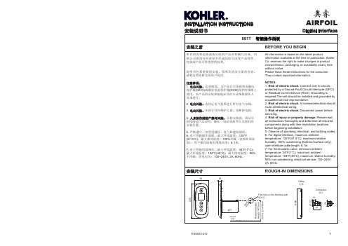
INSTALLATION INSTRUCTIONS 安装说明书Digital Interface奥睿AIRFOILDigital Interface**订购时请说明颜色编号**Color code must be specified when orderingSERVICE PARTS 零 件 图881T 智能操作面板1159749**UI Assembly 智能控制面板奥睿AIRFOIL1681.145Cable 电缆1167860Connector Kit 接头组件INSTALLATION INSTRUCTIONS 安装说明书Digital Interface奥睿AIRFOIL有害物质统计表○:表示该有害物质在该部件所有均质材料中的含量均在GB/T 26572现行有效版本规定的限量要求以下。
×:表示有害物质至少在该部件的某一均质材料中的含量超出GB/T 26572现行有效版本规定的限量要求。
注:本表格提供的信息是基于供应商提供的数据及科勒公司的检测结果。
本产品应用环保设计理念,在当前技术水平下,所有有害物质的使用已经控制到了最低程度,科勒公司会 继续努力通过改善现有技术来减少这些物质的使用。
本产品的“环保使用期限”为10年,科勒公司根据产品设计特性指定该期限。
只有在本产品使用说明书所述的正常情况下使用本产品时,“环保使用期限”才有效。
Statistics of Contents of Toxic or Hazardous Substances or ElementsConnection Assy Control Panel Assy ×○○○○○×○○○○○Mounting Assy○○○○○○Part name Toxic or Hazardous Substance or ElementsLead (Pb )Mercury (Hg )Cadmium (Cd )Hexavalent Chromium (Cr (VI ))Polybrominated biphenyls (PBB )Polybrominated Diphenyl Ethers (PBDE )○:Indicates that the substance in the material composition is below the high limits of the current requirements in GB/T 26572.×:Indicates that at least one of the homogeneous substance in the material composition is below the high limits of the current requirements in GB/T 26572.Note: the information provided is based on the supplier data and Kohler inspection results. The product is designed not to hurt the environment. Under current technology, all hazardous materials have been used in the smallest amounts possible. Kohler will strive to reduce the use of these hazardous materials used in this product.The product “service life for environment protection” is 10 years; Kohler Company will specify product service life based on product characteristics. The product “service life for environment protection” is only effective when the product is used as described in the product specification.连接组件控制面板组件×○○○○○×○○○○○安装组件○○○○○○部件名称有害物质名称铅(Pb )汞(Hg )镉(Cd )六价铬(Cr (VI ))多溴联苯(PBB )多溴二苯醚(PBDE )质量担保WARRANTY自购买之日起,科勒公司对该产品在正常使用下的制造和质料上的瑕疵提供三年的质量担保。
南黎科技三维扫描测量系统用户使用手册说明书
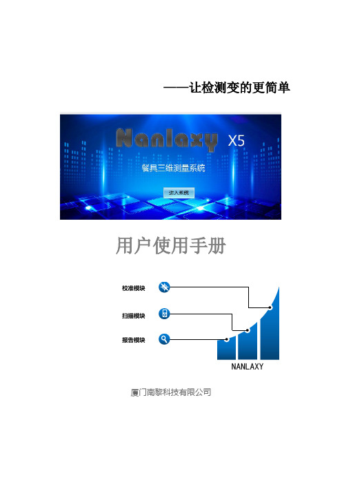
扫描标记点
优化标记点
设置背景面 标记点
保存扫描物件 的文件
扫描物件的 网格化
激光面片的 扫描
激光面片扫 描的设置
-8-
2、标记点扫描的设置
如图设置好适合餐具物件三维扫描的数值设置,如图一、图二设置。
图一
图二
3、扫描标记点操作
(1)选择扫描控制的“标记点”,点击“开始”,对扫描的工件进行激 光标记点的扫描,确保每一个点扫描完成后,点击“停止”。完成标记点扫描 操作。
-2-
三 运行环境
3.1 硬件设备 本系统需自带工作站机型便携式笔记本电脑。 打印机 windows 支持的打印机
四 使用过程
4.1 操作界面中主要对象使用说明: 1 菜单 2 页框 3 按钮 4 文本框 5 下拉列表框 6 单选按钮 7 微调框 8 滚动条 各类对象的使用方法介绍如下: 1 菜单 1) 图示:菜单的形式如下图所示:
1.2 背景 随着社会化的发展,现在的产品越来越趋向造型化、多样化、个性化。在生产制造过程 中需要对产品进行检测。 对于曲面造型复杂的产品高精度检测,这对于工业三维检测 工程是个大的挑战。 目前市场上大多以接触式的量测方式进行检测,有需制作精密的 检测工具,有需设计治具来定位,再用 CMM 三坐标进行测量,操作都相当的繁琐,得 准备相当复杂的前期工作和复杂的计算过程。所以就需要简单操作的三维检测,改变过 去检验的方法,以快速扫描的技术将量测物件资料,再以操作便捷的比对软件进行自动 分析计算,自动产生简而易懂的分析报表,达到产品检测的效果。该系统由厦门南黎科 技有限公司开发。使用者是车间人员、检测人员及有关人员。本系统广泛应用于航空航 天、汽车/轨道交通、机械制造、医疗康复、影视数字艺术、教学科研、文化遗产保护、 3D 打印、VR/AR 等领域,帮助企业实现品质、效率最优解,开拓更广的三维数字化领 域。满足高端制造领域的多项应用需求,包括三维检测,仿真模拟,逆向工程及产品改 造等。
ADI18FITFactoryIT系列隔离型模拟量输入模块用户手册-Contec

ADI12-8(FIT)
i
目录
I/O 地址映射一览..............................................................................17 FactoryIT 产品的共通规格 ..............................................................19
第 5 章 单元的安装............................................................................... 13 安装到 DIN 导轨上................................................................. 13
第 6 章 用作 CPU-SB10(FIT)的设备模块 ........................................... 16 起始 I/O 地址 .................................................................................... 16
第 4 章 模块间的堆叠式连接............................................................... 10 安装模块............................................................................................ 10
第 3 章 连接到外部设备......................................................................... 6 接插件.................................................................................................. 6 接插件的连接方法.................................................................... 6 接口接插件的信号分配............................................................ 7 连接模拟输入信号.............................................................................. 8 差动输入方式接线的例子........................................................ 8
- 1、下载文档前请自行甄别文档内容的完整性,平台不提供额外的编辑、内容补充、找答案等附加服务。
- 2、"仅部分预览"的文档,不可在线预览部分如存在完整性等问题,可反馈申请退款(可完整预览的文档不适用该条件!)。
- 3、如文档侵犯您的权益,请联系客服反馈,我们会尽快为您处理(人工客服工作时间:9:00-18:30)。
4.图形文件编写方法本系统使用Visual C++ 6.0作为开发测试程序的工具,测试程序以动态连接库的形式生成,由系统操作软件调用执行。
测试程序包括两部分:➢图形文件:用于描述测试图形及图形顺序流向控制➢测试程序:产生测试程序动态连接库文件4.1 图形文件的生成、运行简介RUN_PA TTERN( )图形文件是给定格式的文本文件,先在任意文本编辑器环境下编辑图形文件的ASCII源文件,然后执行ComplieDlg.exe程序编译源文件,转换成与测试系统硬件相适应的图形文件二进制目标文件。
测试程序执行函数LOAD_PATTERN()函数,把目标图形文件装载到测试系统的存储器,设定好启动点,执行RUN_PATTERN()函数,启动测试。
4.2 图形文件编写步骤标准图形文件以.mdc为扩展名,文件的第一行为“MEM_SOURCE_15;”。
●定义管脚以“PINDEF”为开始标记,定义管脚及管脚组●定义管脚与通道对应关系以“PIN_TO_CHANNEL”为开始标记,定义管脚与通道的对应关系●编辑图形指令及数据以“MAIN_F”为开始标记,编辑测试图形的流程及图形●结束标志以“END.”为结束标记,结束图形文件的编辑●图形文件编译转换图形文件编辑完成后,在CompileDlg.exe程序环境下,填写或浏览(查找)要编辑的文件 -> 编译 -> 执行编译转换。
转换成与源文件相同名称,扩展名为 .mdv的二进制文件。
如源文件有错误,提示错误行号,错误原因。
(参考2.6)4.3 图形文件格式源文件:ASCII 文件 .mdc文件4.3.1第一行:MEM_SOURCE_15; --------第一行必须以“MEM_SOURCE_15;”开始,作为图形文件的标志4.3.2管脚定义:PINDEF: -------- 管脚定义开始。
<管脚名称> = < I | O | IO 〉,< BIN >,(通道号)-------- 用二进制方式编写图形的管脚定义〈管脚组名称〉(数值..数值) = < I | O | IO >,< HEX >,(通道号)------- 用十六进制方式编写图形的管脚定义I:表示为输入管脚O:表示为输出管脚IO:表示为输入/输出管脚[范例]:OUTP = O , BIN , ( 9 )IN1 = I , BIN , ( 10 )DATA(0..7) = IO, HEX , ( 8,7,6,5,4,3,2,1 )ADDR(0..5) = I , HEX , ( 12,13,14,18,19,20 )4.3.3 管脚到通道定义PIN_TO_CHANNEL: --------从第一列开始,在下一行开始编辑管脚与通道对应关系[范例]:1 = 72..10 = 48..40管脚与通道对应关系语句由两部分组成,第一部分是管脚号,第二部分是通道号,用“=”号分开,可以有两种格式,如范例。
注意:必须一一对应,管脚数与通道数要相等。
4.3.4 图形指令及数据段标记MAIN_F: -------- 必须从第一列开始,图形指令及数据段开始标志,表示下面的语句是指令和数据。
图形指令由多个指令段组成,每段由START_INDEX()开始,HALT (图形)结束。
图形指令有四种格式。
指令(图形)标号指令(图形)指令,参数(图形)标号指令,参数(图形)注:无标号时第1列必须为空格标号必须从第1列开始指令与图形之间、参数与图形之间必须空格4.3.5 起始点定义START_INDEX (起始点标号) -------- 必须从第一列开始,起始点标号可为0至47间的一个数字。
起始点标号用于在执行图形时,标明执行哪一段图形。
在Visual C++中编写测试程序时,在调用函数RUN_PATTERN( )时,第1个参数就是起始点标号,与此定义相同,相互对应使用。
4.3.6 图形结束END. -------- 必须从第1列开始,标志图形文件结束。
4.3.7 注释{ } -------- 注释一行// -------- 注释一行或在一条指令的结尾注释4.4 指令及数据格式说明1.指令:INC 顺次走一步,执行一次图形RPT,n 重复送该图形n+1次,n 最大不能超过4095LDC,n 为LOOP循环指令定义循环次数,n是LOOP指令的循环次数,最大值不能超过4095,最多可嵌套装三次n值LOOP,标号如LDC装入的n值不等于0: n减1,跳转到标号.如LDC装入的n值等于0: 顺次往下走,LOOP指令支持3层嵌套.GOTO,标号跳转到标号GONP,标号从标号开始,如失效: 跳转到标号,如不失效,到下一图形。
LDF 动态测量时的标志,与JMP配合使用,JMP,标号动态测量时,从标号开始,到JMP语句循环执行。
HALT 送该图形后停止,图形发生器工作结束,每个起始点START_INDEX对应1个HALT. 2.存储器测试指令LDAR1,nn(max=24位) 地址计数器1装载,把当前图形中地址管脚对应的F数据装载到内部地址计数器1中.LDAR2,nn(max=24位) 地址计数器2装载,把当前图形中地址管脚对应的F数据装载到内部地址计数器2中.ADDR1 当前图形送出后把地址输出取地址计数器1的值ADDR2 当前图形送出后把地址输出取地址计数器2的值INCAR1 地址计数器1加1,当前图形送出后把内部地址计数器1加1INCAR2 地址计数器2加1,当前图形送出后把内部地址计数器2加1DECAR1 地址计数器1减1,当前图形送出后把内部地址计数器1减1DECAR2 地址计数器2减1,当前图形送出后把内部地址计数器2减1注意:图形指令的第一列必须是空格标号必须从第一列开始,不能空格3.数据格式0、1: 二进制方式,0为输入低,1为输入高L、H: 二进制方式, L为输出低,H为输出高T: 十六进制方式,表示后面数据为输出X: 表示对应的通道不驱动,不测试[范例] m74ls32.mdc 图形文件MEM_SOURCE_15;PINDEFINPUT(1..8) = I, HEX, (1,2,4,5,43,44,46,47)OUT(1..4) = O,HEX, (3,6,42,45)PIN_TO_CHANNEL1..6 = 1..68..13 = 42..47MAIN_F{D M F C}START_INDEX(0)INC (00 T0)INC (55 TF)INC (AA TF)INC (FF TF)HALT (FF TF)START_INDEX(1)INC (00 TX)HALT (00 TX)START_INDEX(2)INC (FF TX)HALT (FF TX)END.5.用户指令目前JC-3166测试系统提供的用户指令共28 条,指令列表如下,用户可根据顺序查询详细说明。
用户指令目录项目指令名称注释1 PMU_CONDITIONS( ) 设置PMU测量条件2 PMU_MEASURE( ) PMU测量3 SET_DPS( ) 设置DPS条件4 DPS_MEASURE( ) DPS测量5 DPS_OFF( ) 关闭DPS6 FORMAT( ) 格式化波形7 SET_INPUT_LEVEL( ) 设置输入参考电平8 SET_OUTPUT_LEVEL( ) 设置输出参考电平9 LOAD_PA TTERN( ) 装入图形文件到测试仪的内存10 RUN_PA TTERN( ) 执行一段图形11 SET_PERIOD( ) 设置时钟周期12 SET_TIMING( ) 设置时钟13 MASK_CHANB_FAIL( ) 设置屏蔽通道板失效位14 RESUME_CHANB_FAIL( ) 取消屏蔽通道板失效位15 READ_NOM_CHANB( ) 非屏蔽通道板失效状态下读通道板的测试数据16 READ_MASK_CHANB( ) 屏蔽通道板失效状态下读通道板的测试数据17 SET_CAT( ) 向外设发送打点指令18 SET_EOT( ) 向外设发送测试结束指令19 SET_MASKJMP( ) 屏蔽JMP状态20 CLEAR_MASKJMP() 清除屏蔽JMP状态指令21 SET_RELAY() 闭合指定继电器,其他继电器打开22 CLOSE_RELAY ( ) 闭合指定继电器,其他保持原状态23 CLEAR_RELAY() 清继电器24 Sleep() 延时(单位:ms)25 BIN()设置分箱号26 SHOW_RESULT() 显示测试结果到显示设备27 READ_PC() 读当前图形指针位置28 CLEAR_ALL() 总清5.1 PMU_CONDITIONS ( )[函数原形]void PMU_CONDITIONS (unsigned int Mode, double Value, unsignedint Value_Unit,double Clamp_Value,unsigned intClamp_Unit);[功能]设置PMU的测试条件,在使用精密测量单元PMU 测量前先设置好,选用不同的模式,决定PMU测量方法。
箝位值作为限流或限压的保护值,并且根据箝位值自动选择测量量程。
[参数]Mode :测量模式,有三种选择:DMV ------ 直接测压FVMI ----- 加压测流FIMV ----- 加流测压Value :施加值范围:电压:±15V电流:±250mAValue_Unit :施加单位FVMI方式,单位可以选V 或MVFIMV方式,单位可以选单位可以选MA 或UA Clamp_Value:箝位值范围:电压:0 ~15V电流:0 ~250mAClamp_Unit:箝位单位DMV 方式, 施加值无意义,箝位值是电压, 单位可以选V 或MVFVMI方式,电流箝位, 单位可以选MA 或UAFIMV方式,电压箝位, 单位可以选V 或MV[范例]设置PMU测量模式为加压测流方式,施加电压5V,箝位电流10mA。
PMU_CONDITIONS (FVMI,5,V,10,mA)5.2 PMU_MEASURE ( )[函数原形]BOOL PMU_MEASURE (CString csPin, unsigned int tDelay,CString csItem, CString csUnit,double fUpLimit,double fDnLimit);double PMU_MEASURE (unsigned int pin,unsigned int tDelay);[功能]使用PMU测量直流参数。
第一种类型的函数测量直流参数,比较上下限,返回PASS,FAIL值第二种函数类型直接测量单一通道,返回测量值[参数]csPin :通道号, 范围:1 ~ 64tDelay :测量延迟时间, 单位毫秒csItem :测量项目名称csUnit :测量单位fUpLimit :测量结果上限值,如无上限值,填写No_UpLimit。
