RT9011-SSGQW中文资料
RT9610CGQW规格书

2
DS9610C-01 April 2016
RT9610C
Functional Block Diagram
VCC BOOT
POR UGATE EN VCC R PWM R Tri-State Detect Control Logic Shoot-Through Protection VCC LGATE GND PHASE
Features
Drives Two N-MOSFETs Adaptive Shoot-Through Protection 0.5Ω On-Resistance, 4A Sink Current Capability Supports High Switching Frequency Tri-State PWM Input for Power Stage Shutdown Output Disable Function Integrated Boost Switch Low Bias Supply Current VCC POR Feature Integrated
Ordering Information
RT9610C Package Type QW : WDFN-8L 2x2 (W-Type) Lead Plating System G : Green (Halogen Free and Pb Free)
Note : Richtek produVCC LGATE GND PWM
WDFN-8L 2x2
Functional Pin Description
Pin No. 1 2 3 4 Pin Name EN PHASE UGATE BOOT Pin Function Enable Pin. When low, both UGATE and LGATE are driven low and the normal operation is disabled. Switch Node. Connect this pin to the source of the upper MOSFET and the drain of the lower MOSFET. This pin provides a return path for the upper gate driver. Upper Gate Drive Output. Connect to the gate of high side power N-MOSFET. Floating Bootstrap Supply Pin for Upper Gate Drive. Connect the bootstrap capacitor between this pin and the PHASE pin. The bootstrap capacitor provides the charge to turn on the upper MOSFET. Control Input for Driver. The PWM signal can enter three distinct states during operation. Connect this pin to the PWM output of the controller. Ground. The exposed pad must be soldered to a large PCB and connected to GND for maximum power dissipation. Lower Gate Drive Output. Connect to the gate of the low side power N-MOSFET. Input Supply Pin. Connect this pin to a 5V bias supply. Place a high quality bypass capacitor from this pin to GND.
901系列技术说明书

单机引擎汽机 SERVICE LETTER 产品说明书
18256040 thru 18256684
January 5, 2023
Single Engine
MANDATORY
SERVICE LETTER
ቤተ መጻሕፍቲ ባይዱ
SEL-28-10
182J 182K
182L 182M 182N 182P
Single Engine
MANDATORY
SERVICE LETTER
SEL-28-10
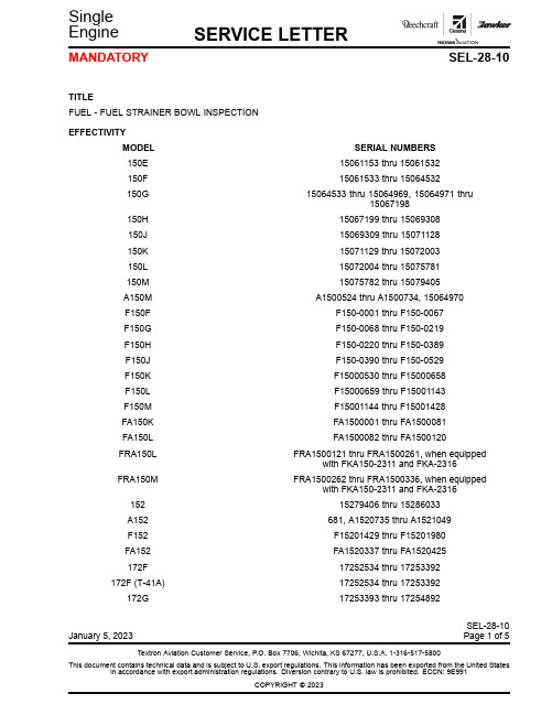
TITLE FUEL - FUEL STRAINER BOWL INSPECTION
EFFECTIVITY MODEL 150E 150F 150G
150H 150J 150K 150L 150M A150M F150F F150G F150H F150J F150K F150L F150M FA150K FA150L FRA150L
F17200754 F17200755 thru F17200804 F17200805 thru F17201034 F17201035 thru F17201514 F17201515 thru F17202039 F17202040 thru F17202254 680, R1722000 thru R1723454 FR17200591 thru FR17200675 17700001, 17700003 thru 17701164
FRA150M
152 A152 F152 FA152 172F 172F (T-41A) 172G
SERIAL NUMBERS 15061153 thru 15061532 15061533 thru 15064532 15064533 thru 15064969, 15064971 thru
浩特威缄飞航天技术有限公司产品说明书:模型90071脚本翼端、反向光、位置灯组装
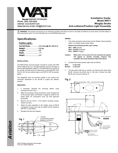
A v i a t i o nPhone: (860) 526-9504Internet: Sales/Service e-mail: info@©2016 Whelen Aerospace Technologies Form No.14A20A (082619)WARNING: This product can expose you to chemicals including Lead which is known to the State of California to cause cancer and birth defects or other reproductive harm. For more information go to www.P65Warnings.ca.g ov.Installation Guide:Model 90071Wingtip StrobeAnti-collision/Position Light Assembly18AWG TEFLON1.79110°70°1.08.151.66RED(+14or +28VDC)BLACK(-)GROUND POS 1 - RED(ANODE)POS 2 - BLACK(CATHODE)POS 3 - WHITE(TRIGGER)TAIL LIGHT WIRES (BLUE)NO POLARITYLEAD LENGTH 6.00"±1.00"2.461.835.631.35DIA..501.00.881.75.140 DIA.(3) MOUNTING HOLES FOR #6-32 SCREWSSpecifications:Position Lights -Current Draw ................ 2.0 Amps @ 28 Volts D.C.Weight ........................... 0.8 lbs.Length ........................... 5.6”Width ............................. 1.7”Height ............................ 2.4”INSTALLATION...The A600 Series must be properly mounted to comply with FAR Part 91.205(c-2) & (c-3). The light assembly must be mounted so that the light distribution pattern is not obstructed by any parts of the aircraft. A limited amount of obstruction is permitted (Ref. FAR Part 23.1401 for anti-collision lights, and FAR 23.1387 for position lights).The baseplate must be mounted parallel to the vertical and horizontal centerlines of the aircraft to project the patterns properly.MOUNTING...1.If necessary, fabricate the mounting pattern using dimensions found in fig. 1.2.Make the necessary wiring connections using 18 gage wire for the position lights, and Whelen 16 gage 3/c cable for the strobe lights. All connections must use FAA approved techniques.3.Remove the two (6-32 x .312) retainer mounting screws,retainer and lens.4.Attach the base assembly to the wingtip using (3) #6-32countersunk screws (unit may be sealed around periphery with RTV or equivalent).5.Re-attach the lens and retainer.WIRING...1.The strobe connector should plug into the Whelen interconnecting cable, or a Whelen strobe power supply.Observe the following strobe color coding:PIN 1 - RED (Anode)PIN 2 - BLACK (Cathode)PIN 3 - WHITE (Trigger)Caution:When pins 1 & 2 or pins 2 & 3 are reversed, the system will appear to operate normally, however this condition will cause premature flash tube failure.2.Connect the forward position light wires as follows:RED - (+) 28 volts BLACK - (-) Ground3.The tail position light has no polarity, as noted by both wires being BLUE. Connect one BLUE wire to +28 volts. Connect the other BLUE wire to ground (see fig. 2).Fig. 1Fig. 2NOTE:LENS/RETAINER ASSEMBLY (A612-D) P/N 02-0350071-35 CONSISTS OF AN RF COATED LENS ELECTRICALLY BONDED TO THE ALUMINUM RETAINER. THE BOND MAY EXHIBIT GAPS OR SEPARATION. THIS IS ACCEPTABLE. THIS RF BOND IS NOT A SEAL.。
rt8901参数
rt8901参数摘要:1.引言2.rt8901 参数介绍2.1 基本参数2.2 性能参数2.3 功能参数3.rt8901 参数作用3.1 提高设备性能3.2 增强数据传输能力3.3 实现多功能应用4.rt8901 参数在实际应用中的优势4.1 稳定可靠4.2 高效节能4.3 易于集成5.结论正文:rt8901 参数是在rt8901 这款产品中,为保证其性能和功能而设定的一系列指标。
本文将详细介绍rt8901 参数,并分析其在实际应用中的优势。
首先,我们来了解一下rt8901 参数的基本情况。
rt8901 参数包括了基本参数、性能参数和功能参数。
基本参数主要包括了产品尺寸、重量、外观等;性能参数主要包括了传输速率、工作电压、功耗等;功能参数主要包括了数据处理能力、通信接口种类等。
rt8901 参数在提高设备性能、增强数据传输能力和实现多功能应用方面起到了关键作用。
例如,通过调整rt8901 参数,可以优化其数据处理能力,使得设备在处理大量数据时更加稳定和高效。
同时,通过调整rt8901 参数,还可以增强其通信接口的种类和数量,从而实现设备的多功能应用。
在实际应用中,rt8901 参数的优势得到了充分体现。
首先,由于rt8901 参数的调整,使得设备在运行过程中更加稳定可靠,大大降低了设备故障的风险。
其次,rt8901 参数的调整也有助于提高设备的节能效果,从而降低了设备的运行成本。
最后,rt8901 参数的调整使得设备更加易于集成到各种应用场景中,提高了设备的灵活性和适应性。
综上所述,rt8901 参数在提高设备性能、增强数据传输能力和实现多功能应用方面起到了关键作用,同时在实际应用中也展现出了其稳定可靠、高效节能和易于集成等优势。
海士卡基立方冰块机零配件清单说明书

No.4253 No.248
CONT Plug UK & MIDDLE EAST OCEANIA CHINA
DCM-120KE-P DCM-120KE-P
FT10416F0 FT20416F0 FST0508F0 P02552-01 263224M01 264001M01 376454M01 377811M01 376455M01 420470-06 427902-05 427902-04 FSK0408S0 259891P01 P02697-01 P02698-01 P02760-01 P00193-01 448949-01 121899M01 121900M01 121901M01 FSG0408S0 121228P01 341489G01 376725M01 121230P02 379018M01
50Hz 50Hz / 60Hz
50Hz 50Hz 50Hz 50Hz 50Hz 50Hz / 60Hz 50Hz 50Hz
Auxiliary Codes
Auxiliary Code Breakdown
The auxiliary code is the first two characters in the serial number. The first character indicates the year. Years progress or regress in alphabetical order. The series runs from "A" through "V" and the letters "I" and "O" are skipped. The second character indicates significant part changes within a year. Base is "0" and this number advances for each change. In cases where there is a letter in parentheses, this designates the month. This is the last character in the serial number. The series runs from "(A)" through "(M)" and the letter "(I)" is skipped. This designation is only included when identifying a parts change within an auxiliary code.
RT9011-MMGQW资料

GND
元器件交易网
RT9011
Typical Application NhomakorabeaCircuit
VIN
Preliminary
VIN CIN 1uF EN1 VOUT2 EN2 GND COUT2 1uF VOUT2 VOUT1 RT9011 Chip Enable COUT1 1uF VOUT1
元器件交易网
RT9011
Absolute Maximum Ratings
z z
Preliminary
(Note 1) 6V 6V 0.455W 0.606W 220°C/W 165°C/W 260°C −65°C to 150°C 2kV 200V
Supply Input Voltage -----------------------------------------------------------------------------------------------------Other I/O Pin Voltages --------------------------------------------------------------------------------------------------z Power Dissipation, PD @ TA = 25°C TSOT23-6 ------------------------------------------------------------------------------------------------------------------WDFN-6L 2x2 -------------------------------------------------------------------------------------------------------------z Package Thermal Resistance (Note 4) TSOT23-6, θJA -------------------------------------------------------------------------------------------------------------WDFN-6L 2x2, θJA --------------------------------------------------------------------------------------------------------z Lead Temperature (Soldering, 10 sec.) ------------------------------------------------------------------------------z Storage Temperature Range -------------------------------------------------------------------------------------------z ESD Susceptibility (Note 2) HBM (Human Body Mode) ---------------------------------------------------------------------------------------------MM (Machine Mode) ------------------------------------------------------------------------------------------------------
泰和安报价表Ver.201407(7月印制)

目录
一、火灾探测器及接口部件 1 ································································································· 二、现场模块及指示部件 1 ······································································································ 三、各类火灾报警、联动控制器 3 ······················································································ 四、气体灭火控制设备 13 ·········································································································· 五、扩展操作盘 13 ························································································································· 六、机柜、机箱 14 ························································································································· 七、火灾显示盘 14 ························································································································· 八、直流不间断电源 14 ·············································································································· 九、中央管理软件及接口设备 15 ························································································· 十、网络接口设备 15 ··················································································································· 十一、消防广播系统 15 ·············································································································· 十二、消防电话系统 16 ·············································································································· 十三、防爆产品系列 16 ·············································································································· 十四、蓄电池及备品备件 18 ···································································································· 十五、消防应急照明与疏散指示系统 19 ·········································································· 十六、电气火灾监控设备 21 ···································································································· 十七、电气火灾探测器 22 ········································································································· 十八、互感器 23 ······························································································································ 十九、测温式探测器 23 ··············································································································
901继电保护测试仪说明书2(901 Relay Protect Tester Instructions)
901继电保护测试仪901 Relay Protect Tester使用说明书Instructions目录第1章概述 (5)1.1 简介 (5)1.2 功能特点 (6)1.3 技术指标 (8)第2章硬件结构 (10)2.1 总体结构 (10)2.2 装置硬件原理 (10)2.2.1高性能信号处理系统 (10)2.2.2高性能线性功率放大器 (10)2.3 硬件特色 (11)2.3.1一体化的高性能信号处理系统 (11)2.3.2高性能线性功放系统 (11)2.3.3完善的保护功能 (12)2.3.4开关量输入 (12)2.3.5良好的幅频特性及暂态响应 (12)第3章测试软件操作界面 (13)3.1 主菜单 (13)3.2 电压电流 (13)3.2.1测试项目 (14)3.2.2用户界面 (14)3.2.3标签页 (16)3.2.4试验过程 (23)3.3 整组试验 (27)3.3.1用户界面 (28)3.3.2标签页 (30)3.3.3试验过程 (34)3.4 谐波试验 (35)3.4.2标签页 (37)3.4.3试验过程 (39)3.5 状态序列 (41)3.5.1用户界面 (41)3.5.2标签页 (43)3.5.3试验状态的操作 (49)3.5.4试验过程 (51)3.6 时间特性 (52)3.6.1试验原理 (52)3.6.2试验内容 (53)3.6.3试验结果 (55)3.7 线路保护 (57)3.7.1测试项目 (57)3.7.2用户界面 (57)3.7.3标签页 (59)3.7.4试验过程 (64)3.8 阻抗特性 (65)3.8.1用户界面 (65)3.8.2标签页 (67)3.8.3试验过程 (72)3.9 差动试验 (73)3.9.1用户界面 (73)3.9.2标签页 (75)3.9.3试验过程 (80)3.10 并列同期 (81)3.10.1用户界面 (81)3.10.2基本参数 (83)3.11 故障再现 (86)3.11.1用户界面 (86)3.11.3试验过程 (90)3.12 振荡试验 (92)3.12.1用户界面 (92)3.12.2试验参数 (92)3.12.3图形显示 (93)第1章概述1.1 简介901继电保护测试仪是结合电力现场情况、众多电力用户经验自主研发的便携式新产品,采用高性能开关电源、高性能D/A技术、先进的DSP+FPGA硬件平台、高品质线性功放等技术,每工频周波输出800点,输出电压、电流波形精度高、测试功能完善,能很好地满足电力自动化设备测试需要,适用于变电站、发电厂、电力设备用户、大型工矿企业、科研院所等需要高精度信号源和多种专用测试信号源的场合。
RT-9000L说明书(双页)

3.按
鍵設定所有測試設定項目,如導通阻抗、測試電壓、絕緣阻抗、高
壓時間與範圍、測試條件等等,請參閱第 6-3 以後章節。
4. 如 果 導 通 阻 抗 設 定 在 2 Ω (含 )以 下 時 , 須 先 進 行 測 試 點 歸 零 校 正 。 選 擇
鍵,請參閱章節 6-7 ( A. 治 具 歸 零 )
500,600,650,700,800V ( 900~ 1500VDC) 50VDC ~ 800VDC?5% ( 900 ~ 1500VDC?5% ) 0.01 ~0.09mA,0.1 ~0.9mA,1 ~5mA -20% ~ 0% 128 點/秒 0.01s ~ 0.1s,0.2s,0.5s,1s,2s,5s,10s,30s & 60sec. 500K ~ 500MΩ ( 1 GΩ ) RT-9801M/H 升級為 RT-9801CM/CH 才有元件測試功能
RT-9801 提供幾項特殊的測試軟體,特別是在高壓測試不但準 確而且快 速,在大量生產測試上最合乎經濟及效益,一般而言執行高壓測試占大部份測 試時間,因此測試速度快慢與否,對於降低生產成本十分重要。另一項特殊的 測 試 軟 體 為最短 路 徑判 斷 , 對 於 提 供導 通 量 測 、電 阻 元 件及不 良 品 短 路 /斷 路 位置辨認,RT-9801 可正確告知問題位置,維修者可以減少猜測的時間浪費, 以及判斷錯誤所造成的損失,對於降低維修成本十分重要。。
羅因電子
TEL : 8862– 8667–1488 FAX : 8862– 8667–1097
RT-9801M V3.33 I/O Board : 2 < 2P-0S > File : ? ? ? ?
LCD 將會進入(如左)機台之主畫面。
SSG-W 电动滤水器说明书
SSG型自动反冲洗滤水器使用说明书SSG Auto Back Flushing StrainerInstruction四川高精净化设备有限公司SICHUAN FINE PURIFICATION EQUIPMENT CORP.LTD一、结构和工作原理Structure and Working PrincipleSSG型自动反冲洗滤水器主要由罐体、刷式清洗机构、减速传动机构、电动排污阀等部份组成。
其中滤芯、传动轴等部件采用不锈钢材质制作,具有耐腐蚀、经久耐用的特点。
正常过滤状态时,电动排污阀关闭,电动减速机不启动,当满足设定的清污、排污工况时,电动排污阀打开,滤水器电动减速机启动,带动轴及清洗刷转动,使附在滤芯内腔上的杂质,借助刷子刷洗掉,经排污管,电动排污阀排出机外。
SSG auto back flushing strainer consists of cylinder, brushing cleaning structure, reducer driving structure, electric sewage drainage valve etc. in which the filtration cartridge and driving structure are made of stainless steel, corrosion resistance and long use life. During strainer normal working, electric sewage drainage valve is closed and electric reducer stops. When appreciated cleaning and drainage working condition rises, electric sewage drainage valve auto opens and electric reducer starts. Electric reducer drives shaft and starts to brush off the attaching on filtrating cartridge inner wall. They pass the drainage pipe and electric drainage valve and are discharged outside the strainer.SSG型自动反冲洗滤水器的清污、排污工况如下:Cleaning and drainage working condition of SSG auto back flushing strainer shows as below:1、定时清污:定时清污控制箱内PLC控制可设定动作时间2~24小时,出厂时一般设为24小时。
微透镜阵列镜片超声波清洗机

微透镜阵列镜片超声波清洗机微透镜阵列,又称复眼透镜,是尺寸为微米量级的小透镜按一定规律以一维或二维方式排列构成的光学元件。
在10 mm2 的面积上可以有上万甚至上百万个小透镜,因此具有十分独特的功能。
具有体积小、重量轻、集成度高等特点。
微透镜阵列在可以应用到许多领域,比如波前传感、光聚能、光束整形/匀光、光纤耦合、医疗器械、以及3D 成像等。
微透镜阵列镜片技术参数:基底材料:石英、光学玻璃。
排列尺寸:四边形、六边形、随机排列。
基底材料石英、光学玻璃清洗用超声波清洗机:超声波清洗机是一种常用于清洗物品的设备,通常利用超声波的震动效应来去除污垢和污染物。
超声波清洗机的优势:高效清洁:由于超声波的作用,清洁效果更加彻底,可以清除微小空隙和死角中的污垢。
无损清洗:超声波的震动可以防止物品受到机械刮擦,避免表面损伤。
节省时间和劳力:超声波清洗机能够在短时间内完成大量物品的清洗,减少人工劳动和时间成本。
超声波清洗机与清洗剂配合的重要性:清洗剂是指用于协助清除污垢和污染物的化学制剂。
使用清洗剂可以加速清洗过程,并提高清洗的效果。
以下是清洗剂的几个作用:去污能力:清洗剂可以降低污垢的表面张力,使其更容易被去除。
分散和乳化作用:清洗剂可以将污垢分散在溶液中,使其不再重新附着在物品表面。
去除油脂和污染物:清洗剂中的表面活性剂可以与油脂和污染物发生化学反应,从而将其溶解并去除。
因此,使用清洗剂可以提高超声波清洗的效果,尤其是对于一些顽固的污染物,如油脂、涂层和氧化物等。
威固特VGT-1309FS光学超声波清洗机:设备共有13个功能槽,配置有浸泡系统、循环过滤系统、自动恒温系统、抛动系统、超声波清洗系统、慢拉脱水系统、热风烘干系统、离心烘干系统、密闭气缸门系统、抽风装置等。
威固特VGT-1309FS光学超声波清洗机系统配置优势:1、经过超声纯水、超声DI纯水清洗槽清洗,设备顶部加设FFU的效果是为了工件加温后,对灰尘的附着力增强,FFU形成负压可有效减少环境对洗净效果的影响,从而从根本上提高产品合格率。
同飞冷水机说明介绍模板之欧阳道创编
非常感谢您使用同飞制冷公司工业冷却设备!时间:2021.03.06 创作:欧阳道在使用机器前请仔细阅读此说明书!安全规范为了防止出现人身伤害和产品损坏,请严格遵守安全规范。
由于忽视安全规范而进行不正确操作将会引起人身伤害和产品损坏。
通过下面的符号来说明严重的等级。
该手册及设备上符号的意义如下: [危险]高压危险!接触带电部件可能造成电击和灼伤!维护与保养必须由专业技术人员来操作![危险]表面高温!安全报警符号仔细阅读并严格遵守规范以避免危险情况的出现。
身体的任何部位及不耐热的物品必须远离此高温区域;否则会造成人身损害,或财产损失!请就近保存该手册,便于取阅。
该手册应交给使用该产品及从事设备维护的人员。
[危险]请勿在技术要求之外使用;[危险]绝对禁止在爆炸性气体中使用;[危险]机器内有压缩气体,有爆炸危险,请勿拆解;[危险]必须遵守相关的法规及条例;[警告]制冷剂泄漏时:○保持良好通风(有窒息的可能);○不能与皮肤接触(有冻伤的可能);[警告]发生异常时立即停止运转,查明原因之后进行适当处理;[注意]禁止在高温(环境温度高于45℃)、潮湿(有凝露)、极度灰尘、大量水蒸气、油雾及特殊气体中使用;[注意]请勿在产品上放置重物;[危险]起吊时,经确认重量后务必使用产品自身的起吊装置;[警告]产品起吊时避免人员靠近并防止倾倒;[注意]搬运时避免倾斜角度大于45°,防止压缩机故障。
[警告]严禁机器水箱内带有水或者其他液体进行运输!!![警告]安装位置水平,并能支撑机组重量(带脚轮的产品,地面应平整、光洁);[警告]设备四周和上部应留出足够的空间(通常大于1米),以利于空气流动和设备维修;[警告]请勿将设备安装在落叶、昆虫或其他污物容易聚集的地方,以防阻塞风换热器;[警告]设备安装时,应调整好风换热器方向,以利通风并避免阳光直射;[警告]制冷量较大的设备使用时,室内应装有风量合适的排风装置,以防室内空气温度升高影响精密冷却机工作。
- 1、下载文档前请自行甄别文档内容的完整性,平台不提供额外的编辑、内容补充、找答案等附加服务。
- 2、"仅部分预览"的文档,不可在线预览部分如存在完整性等问题,可反馈申请退款(可完整预览的文档不适用该条件!)。
- 3、如文档侵犯您的权益,请联系客服反馈,我们会尽快为您处理(人工客服工作时间:9:00-18:30)。
Richtek Pb-free and Green products are :
`RoHS compliant and compatible with the current require-
ments of IPC/JEDEC J-STD-020.
`Suitable for use in SnPb or Pb-free soldering processes.
cial Standard)
Output Voltage : VOUT1/VOUT2 CM : 1.20V/2.80V, FM : 1.50V/2.80V GK : 1.80V/2.60V, GS : 1.80V/3.30V JG : 2.50V/1.80V, JM : 2.50V/2.80V JP : 2.50V/3.00V, JS : 2.50V/3.30V JN : 2.50V/2.85V, MG : 2.80V/1.80V MM : 2.80V/2.80V, NN : 2.85V/2.85V MS : 2.80V/ 3.30V, PG : 3.00V/1.80V MP : 2.80V/3.00V, PP : 3.00V/3.00V SS : 3.30V/3.30V, SQ : 3.30V/3.10V BM : 1.30V/2.80V
V
P
Q
R
S
--
--
Voltage 2.65 2.7 2.8 2.85 2.9
3
3.1 3.2 3.3
--
--
2
DS9011-05 August 2007
元器件交易网
Function Block Diagram
Preliminary
EN1
0.2uA VREF
Ordering Information
RT9011Note :
Package Type J6 : TSOT-23-6 QW : WDFN-8L 2x2 (W-Type) Operating Temperature Range P : Pb Free with Commercial Standard G : Green (Halogen Free with Commer-
TSOT23-6 ------------------------------------------------------------------------------------------------------------------- 0.455W WDFN-6L 2x2 -------------------------------------------------------------------------------------------------------------- 0.606W z Package Thermal Resistance (Note 4) TSOT23-6, θJA -------------------------------------------------------------------------------------------------------------- 220°C/W WDFN-6L 2x2, θJA --------------------------------------------------------------------------------------------------------- 165°C/W z Lead Temperature (Soldering, 10 sec.) ------------------------------------------------------------------------------- 260°C z Storage Temperature Range -------------------------------------------------------------------------------------------- −65°C to 150°C z ESD Susceptibility (Note 2) HBM (Human Body Mode) ---------------------------------------------------------------------------------------------- 2kV MM (Machine Mode) ------------------------------------------------------------------------------------------------------ 200V
Shutdown and
Logic Control
-
+ Error
Amplifier
MOS Driver
Current-Limit and
Thermal Protection
EN2
0.2uA VREF
Shutdown and
Logic Control
-
+ Error
Amplifier
MOS Driver
Marking Information
For marking information, contact our sales representative directly or through a Richtek distributor located in your area, otherwise visit our website for detail.
RT9011 can operate stably with very small ceramic output capacitors, reducing required board space and component cost. RT9011 is available in fixed output voltages in the TSOT-23-6 and WDFN-8L 2x2 pacmmon Ground.
7
1
VOUT2 Channel 2 Output Voltage.
8
6
VOUT1 Channel 1 Output Voltage.
4, 6
--
NC
No Internal Connection.
Exposed Pad (9)
The exposed pad must be soldered to a large PCB and
1
元器件交易网
RT9011
Typical Application Circuit
Preliminary
VIN
CIN 1uF
VIN VOUT1
RT9011
COUT1 1uF
VOUT1
Chip Enable
EN1 VOUT2
EN2 GND
COUT2 1uF
RT9011 is short circuit thermal folded back protected. RT9011 lowers its OTP trip point from 165°C to 110°C when output short circuit occurs (VOUT < 0.4V) providing maximum safety to end users.
--
GND
connected to GND for maximum power dissipation.
Available Voltage Version
Code C
B
F
W
G
D
Y
H
E
J
K
Voltage 1.2 1.3 1.5 1.6 1.8 1.85 1.9
2
2.1 2.5 2.6
Code T
L
M
N
Applications
z CDMA/GSM Cellular Handsets z Battery-Powered Equipment z Laptop, Palmtops, Notebook Computers z Hand-Held Instruments z PCMCIA Cards z Portable Information Appliances
Pin Configurations
(TOP VIEW)
VOUT1 VIN EN1
65 4 123
VIN 1 EN1 2 EN2 3
NC 4
GND
8 VOUT1
7 VOUT2 6 NC 9 5 GND
VOUT2 GND EN2
TSOT-23-6
WDFN-8L 2x2
Note : There is no pin1 indicator on top mark for TSOT-23-6 type, and pin 1 will be lower left pin when reading top mark from left to right.
`100% matte tin (Sn) plating.
DS9011-05 August 2007
z Wide Operating Voltage Ranges : 2.5V to 5.5V z Low-Noise for RF Application z No Noise Bypass Capacitor Required z Fast Response in Line/Load Transient z TTL-Logic-Controlled Shutdown Input z Low Temperature Coefficient z Dual LDO Outputs (300mA/300mA) z Ultra-low Quiescent Current 27μA/LDO z High Output Accuracy 2% z Short Circuit Protection z Thermal Shutdown Protection z Current Limit Protection z Short Circuit Thermal Folded Back Protection z Tiny TSOT-23-6 and 8-Lead WDFN Package z RoHS Compliant and 100% Lead (Pb)-Free
