uPA855TD-T3中文资料
美国索拉燃气轮机
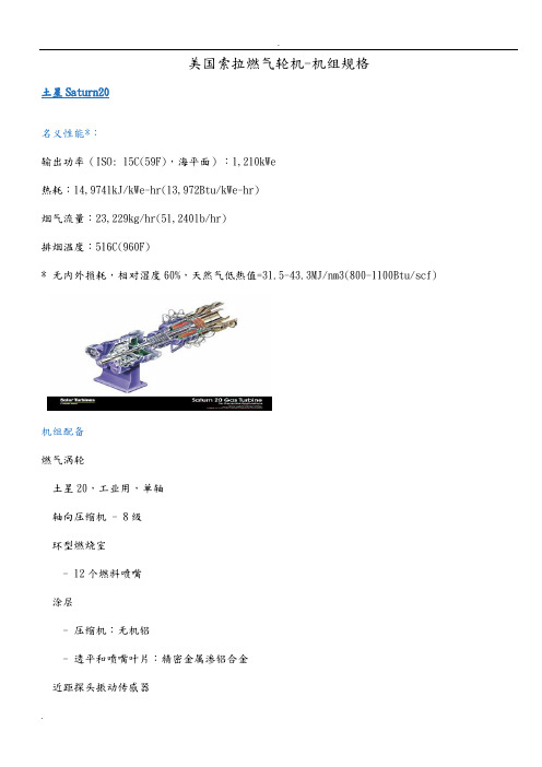
美国索拉燃气轮机-机组规格土星Saturn20名义性能*:输出功率(ISO: 15C(59F),海平面):1,210kWe热耗:14,9741kJ/kWe-hr(13,972Btu/kWe-hr)烟气流量:23,229kg/hr(51,240lb/hr)排烟温度:516C(960F)* 无内外损耗,相对湿度60%,天然气低热值=31.5-43.3MJ/nm3(800-1100Btu/scf)机组配备燃气涡轮土星20,工业用,单轴轴向压缩机 - 8级环型燃烧室- 12个燃料喷嘴涂层- 压缩机:无机铝- 透平和喷嘴叶片:精密金属渗铝合金近距探头振动传感器主要减速装置行星齿轮- 1800或1500rpm- 加速振动传感器发电机凸级,3相,6线,Y型连接,同步带无刷励磁机开式防滴结构衬套轴承速度振动传感器带永磁发电机的固态电压调节NEMA F级绝缘带F温升连续负载额定机组带集液盘的钢制基座直接驱动的交流或气压启动系统天然气燃料系统控制系统- 基于微处理器的可编程逻辑控制- 发电机控制- 振动和温度监视- 自动同步集成的润滑油系统- 透平驱动的滑油泵- 交流提前/快速的滑油泵- 空气/油冷却器- 集成的润滑油箱- 润滑油过滤器文件- 图纸- 质保书- 检验及测试计划- 测试报告- 操作及维护手册透平及机组的工厂测试防风防雨隔音罩半人马座Centaur40名义性能*:输出功率(ISO: 15C(59F),海平面):3,515kWe热耗:12,912kJ/kWe-hr(12,240Btu/kWe-hr)烟气流量:67,004kg/hr(147,718lb/hr)排烟温度:437C(819F)* 无内外损耗,相对湿度60%,天然气低热值=31.5-43.3MJ/nm3(800-1100Btu/scf)机组配备燃气涡轮半人马座40,工业用,单轴轴向压缩机 - 11级环型燃烧室- 10个燃料喷嘴涂层- 压缩机:无机铝- 透平和喷嘴叶片:精密金属渗铝合金近距探头振动传感器主要减速装置行星齿轮- 1800或1500rpm- 加速振动传感器发电机凸级,3相,6线,Y型连接,同步带无刷励磁机开式防滴结构衬套轴承速度振动传感器带永磁发电机的固态电压调节NEMA F级绝缘带F温升连续负载额定机组带集液盘的钢制基座直接驱动的交流启动系统天然气燃料系统控制系统- 基于微处理器的可编程逻辑控制- 发电机控制- 振动和温度监视- 自动同步集成的润滑油系统- 透平驱动的滑油泵- 交流提前/快速的滑油泵- 备用的滑油泵- 空气/油冷却器- 集成的润滑油箱- 润滑油箱加热器- 润滑油过滤器文件- 图纸- 质保书- 检验及测试计划- 测试报告- 操作及维护手册透平及机组的工厂测试半人马座Centaur50名义性能*:输出功率(ISO: 15C(59F),海平面):4,600kWe热耗:12,269kJ/kWe-hr(11,628Btu/kWe-hr)烟气流量:68,680kg/hr(151,410lb/hr)排烟温度:509C(949F)无内外损耗,相对湿度60%,天然气低热值=31.5-43.3MJ/nm3(800-1100Btu/scf)机组配备燃气涡轮半人马座50,工业用,单轴轴向压缩机 - 11级环型燃烧室- 12个燃料喷嘴涂层- 压缩机:无机铝- 透平和喷嘴叶片:精密金属渗铝合金近距探头振动传感器主要减速装置行星齿轮- 1800或1500rpm- 加速振动传感器发电机凸级,3相,6线,Y型连接,同步带无刷励磁机开式防滴结构衬套轴承速度振动传感器带永磁发电机的固态电压调节NEMA F级绝缘带F温升连续负载额定机组带集液盘的钢制基座直接驱动的交流启动系统天然气燃料系统控制系统- 基于微处理器的可编程逻辑控制- 发电机控制- 振动和温度监视- 自动同步集成的润滑油系统- 透平驱动的滑油泵- 交流提前/快速的滑油泵- 备用的滑油泵- 空气/油冷却器- 集成的润滑油箱- 润滑油箱加热器- 润滑油过滤器文件- 图纸- 质保书- 检验及测试计划- 测试报告- 操作及维护手册透平及机组的工厂测试金牛座Taurus60名义性能*:输出功率(ISO: 15C(59F),海平面):5,200kWe热耗:11,882kJ/kWe-hr(11,263Btu/kWe-hr)烟气流量:79,284kg/hr(174,798lb/hr)排烟温度:486C(906F)* 无内外损耗,相对湿度60%,天然气低热值=31.5-43.3MJ/nm3(800-1100Btu/scf)标准机组配置燃气涡轮金牛座60,工业用,单轴轴向压缩机 - 12级环型燃烧室- 12个燃料喷嘴涂层- 压缩机:无机铝- 透平和喷嘴叶片:精密金属渗铝合金近距探头振动传感器主要减速装置行星齿轮- 1800或1500rpm- 加速振动传感器发电机凸级,3相,6线,Y型连接,同步带无刷励磁机开式防滴结构衬套轴承速度振动传感器带永磁发电机的固态电压调节NEMA F级绝缘带F温升连续负载额定机组带集液盘的钢制基座直接驱动的交流启动系统天然气燃料系统控制系统- 基于微处理器的可编程逻辑控制- 发电机控制- 振动和温度监视- 自动同步集成的润滑油系统- 透平驱动的滑油泵- 交流提前/快速的滑油泵- 备用的滑油泵- 空气/油冷却器- 集成的润滑油箱- 润滑油箱加热器- 润滑油过滤器文件- 图纸- 质保书- 检验及测试计划- 测试报告- 操作及维护手册透平及机组的工厂测试金牛座Taurus70名义性能*:输出功率(ISO: 15C(59F),海平面):7,250kWe热耗:10,969kJ/kWe-hr(10,398Btu/kWe-hr)烟气流量:97,908kg/hr(215,851lb/hr)排烟温度:493C(919F)* 无内外损耗,相对湿度60%,天然气低热值=31.5-43.3MJ/nm3(800-1100Btu/scf)标准机组配置燃气涡轮金牛座70,工业用,单轴轴向压缩机- 14级- 可变几何截面- 垂直可分离外壳- 压缩比:16:1- 转速:15,200rpm环型燃烧室- 传统式或倾斜预混合式,干式,低排放(SoloNOx) - 21个燃料喷嘴(传统式)- 14个燃料喷嘴(SoloNOx)近距探头振动传感器透平- 3级,轴流式- 转速:15,200rpm主要减速装置行星齿轮- 1500或1800rpm(50或60Hz)- 加速振动传感器发电机连续负载额定凸级,3相,6线,Y型连接,同步带无刷励磁机开式防滴结构衬套轴承速度振动传感器带永磁发电机的固态电压调节NEMA F级绝缘带F温升机组带集液盘的钢制基座直接驱动的交流启动系统天然气燃料系统控制系统- 基于微处理器的可编程逻辑控制- 燃气轮机和发电机控制- 振动和温度监视- 自动同步集成的润滑油系统- 透平驱动的滑油泵- 提前/快速的滑油泵- 备用的滑油泵- 空气/油冷却器- 集成的润滑油箱- 润滑油箱加热器- 润滑油过滤器文件- 图纸- 质保书- 检验及测试计划- 测试报告- 操作及维护手册透平及机组的工厂测试火星Mars100名义性能*:输出功率(ISO: 15C(59F),海平面):10,695kWe 热耗:11,092kJ/kWe-hr(10,515Btu/kWe-hr)烟气流量:150,386kg/hr(331,545lb/hr)排烟温度:487C(908F)* 无内外损耗,相对湿度60%,天然气低热值=31.5-43.3MJ/nm3(800-1100Btu/scf)标准机组配置燃气涡轮火星100,工业用,双轴轴向压缩机,15级- 可变几何截面- 垂直可分离外壳- 压缩比:17:1(SoloNOx);16:1(传统式)- 转速:15,200rpm环型燃烧室- 传统式或倾斜预混合式,干式,低排放(SoloNOx)- 21个燃料喷嘴(传统式)- 14个燃料喷嘴(SoloNOx)近距探头振动传感器燃气发生器透平- 2级,轴流式- 转速(ISO设计匹配):10,942rpm动力透平- 2级,轴流式- 转速:8,586或8,625rpm主要减速装置行星齿轮- 1500或1800rpm(50或60Hz)- 加速振动传感器发电机连续负载额定凸级,3相,6线,Y型连接,同步带无刷励磁机开式防滴结构衬套轴承速度振动传感器带永磁发电机的固态电压调节NEMA F级绝缘带F温升机组带集液盘的钢制基座直接驱动的交流启动系统天然气燃料系统控制系统- 基于微处理器的可编程逻辑控制- 燃气轮机和发电机控制- 振动和温度监视- 自动同步集成的润滑油系统- 交流电动机驱动、变频驱动控制的滑油泵- 提前/快速及备用的滑油泵- 空气/油冷却器- 集成的润滑油箱- 润滑油箱加热器- 润滑油过滤器文件- 图纸- 质保书- 检验及测试计划- 测试报告- 操作及维护手册透平及机组的工厂测试大力神Titan130名义性能*:输出功率(ISO: 15C(59F),海平面):13,500kWe热耗:10,810kJ/kWe-hr(10,250Btu/kWe-hr)烟气流量:179,770kg/hr(396,390lb/hr)排烟温度:489C(913F)* 无内外损耗,相对湿度60%,天然气低热值=31.5-43.3MJ/nm3(800-1100Btu/scf)标准机组配置燃气涡轮大力神130,工业用,单轴轴向压缩机- 14级- 可变几何截面- 垂直可分离外壳- 压缩比:16:1- 转速:11,200rpm环型燃烧室- 传统式或倾斜预混合式,干式,低排放(SoloNOx) - 21个燃料喷嘴(传统式)- 14个燃料喷嘴(SoloNOx)近距探头振动传感器透平- 3级,轴流式- 速度:11,200rpm主要减速装置行星齿轮- 1500或1800rpm(50或60Hz)- 加速振动传感器发电机连续负载额定凸级,3相,6线,Y型连接,同步带无刷励磁机开式防滴结构衬套轴承速度振动传感器带永磁发电机的固态电压调节NEMA F级绝缘带F温升机组带集液盘的钢制基座直接驱动的交流启动系统天然气燃料系统控制系统- 基于微处理器的可编程逻辑控制- 燃气轮机和发电机控制- 振动和温度监视- 自动同步集成的润滑油系统- 透平驱动的滑油泵- 提前/快速的滑油泵- 备用的滑油泵- 空气/油冷却器- 集成的润滑油箱- 润滑油箱加热器- 润滑油过滤器文件- 图纸- 质保书- 检验及测试计划- 测试报告- 操作及维护手册透平及机组的工厂测试土星Saturn20。
优兰仕数码光电宝说明书

优兰仕数码光电宝说明书前言:近年来,随着科技的飞速发展,数码产品在我们的日常生活中扮演着不可或缺的角色。
而光电宝作为一种便携式数码产品,正在逐渐走进人们的生活。
本说明书将对优兰仕数码光电宝进行详细介绍,以帮助用户更好地了解和使用该产品。
一、产品概述:优兰仕数码光电宝是一款多功能的数码设备,集成了数码显示屏、摄像头、触控屏、充电宝等功能于一体。
外壳采用高质量的塑料材料制成,具有坚固耐用、防水防尘的特点。
设计精巧,携带方便。
二、核心功能介绍:1. 数码显示屏:优兰仕光电宝配备了一块高分辨率的数码显示屏,可流畅播放各类视频、图像和文档。
用户可以通过触控屏来进行操作,简单方便。
2. 摄像头:光电宝内置了一颗高像素的摄像头,可实现拍照和录像功能。
用户可以通过触控屏来调整拍摄参数,如焦距、对焦等,满足不同用户的需求。
3. 触控屏:该设备配备了高灵敏度的触控屏,用户可以通过触摸屏幕上的图标和按钮来控制设备的各种功能,使用起来十分方便。
4. 充电宝:光电宝具备充电宝的功能,内置大容量电池,可为手机、平板电脑等其他数码设备提供持久的电源支持。
三、使用方法:1. 开机:在设备背面找到电源开关,长按数秒即可开启设备。
开机后,屏幕将会显示设备的主界面。
2. 操作界面:主界面上显示了各种应用程序的图标,用户可以通过点击图标来打开对应的应用程序。
在应用程序中,用户可通过触摸屏幕来进行各种操作。
3. 拍照和录像:在摄像头应用程序中,用户可以通过触控屏调整拍摄参数,然后点击拍摄按钮进行拍照或录像。
拍摄完成后,用户可以在相册应用程序中查看和管理拍摄的照片和视频。
4. 充电:当光电宝电量较低时,用户可以通过数码线将设备与电源连接,即可进行充电。
充电过程中,设备会自动显示当前电量,并可通过触控屏幕调整充电参数。
四、注意事项:1. 使用时,请勿将光电宝与尖锐物体放在一起,以免划伤外壳。
2. 请勿将光电宝置于高温或潮湿的环境中使用,以免影响其正常工作。
东芝TDP-T355投影仪中文说明书
12. 不可垂直放置本機
請勿以直立位置把圖像投影至天花 板或其它垂直位置。 因為這可能會 使機器倒下而發生危險。
15. 輔助用具
不可將本機放置在不穩定的手推 車﹑支架﹑三角架﹑框架或桌子 上﹐因為這樣會導致機器墜落﹐從 而使小孩或大人受傷 。 放置在手推 車上的機器在移動時要多加小心﹐ 急停﹑用力過猛﹑不平地面等都可 能導致機器和手推車顛覆。
7. 清掃
從牆上的電源插座上拔下插頭後方 可進行清掃 。 不可使用液體洗滌劑 以及噴霧清潔劑。 請使用軟布進行清潔。
4
5
使用前
注意:請閱讀並遵守本使用說明書以及機器上標示的所有警告和說明事項。並妥善 保管本使用說明書﹐以備日後參考。
5. 熱源
本機放置場所必須遠離熱源﹐如暖 氣機﹑熱調節器﹑加熱爐以及其它 發熱產品(包括放大器等)。
S3125A
16. 損壞維修服務需要
在出現如下情況時﹐將機器的插頭 從插座上拔下﹐與合資格的維修人 員商談。 當電源線或插頭破損時; 當機內灑入液體或有異物掉入時; 當機器遭雨淋或水澆之後; 如果按照操作說明來操作﹐卻不能 使機器正常工作時﹐請只對說明書 上指定的控制操作進行調節;因為 如果對說明書指定以外的控制操作 進行不當的調節﹐可能會損壞機 器﹐即使之後請訓練有素的技術人 員來調節機器到正常的狀態﹐也要 花上相當的時間;
8. 電源線的保護
電源線應設置在踩不到的地方﹐也 不可將其它物品置於電源線之上 。 對於插頭﹑插座以及從機器中引出 的電源線都要特別注意。
重要安全說明(續)
10. 雷電
為了防止雷電引起的損壞或當長時 間不使用本機器時﹐應將其從電源 插座上拔下 。 這樣可以有效地防止 雷電或電網波動造成的損害。但 是﹐當打雷或閃電時﹐請勿觸摸本 機和任何連接電纜和/ 或設備。這樣 可以防止受到電涌的電擊。
DPT-3W说明书(V3.10)

DPT-3W说明书(V3.10)DPT-3W分布式微机变压器综合保护装置_________________________________________ 技术和使用说明书南京恒星自动化设备有限公司SUN NANJING AUTOMATION EQUIPMENT CO.,LTDDPT-3W技术及使用说明书南京恒星自动化设备有限公司版权所有 2021.03(V1.0)本说明书适用于DPT-3W保护装置,V2.00版本本说明书和产品今后可能会有小的改动,请核对实际产品与说明书的版本是否相符。
1DPT-3W技术及使用说明书目录1.概述 ........................................................................... ................................................................. 4 1.1 DP系列产品概述 ........................................................................... ..................................... 4 1.2 应用范围 ........................................................................... .................................................. 4 1.3 保护配置 ........................................................................... .................................................. 4 1.4性能特征 ........................................................................... ................................................... 5 1.5规范性引用文件 ........................................................................... ....................................... 5 2.技术条件............................................................................ ......................................................... 6 2.1环境条件 ........................................................................... ................................................... 6 2.2电源 ........................................................................... ........................................................... 7 2.3 交流回路 ........................................................................... .................................................. 7 2.4过载能力 ........................................................................... ................................................... 7 2.5装置的主要功能 ........................................................................... ....................................... 8 2.6主要技术性能指标 ........................................................................... ................................... 9 2.7测量元件 ........................................................................... ................................................. 10 3.工作原理............................................................................ ....................................................... 10 3.1.差动电流与制动电流 ........................................................................... .......................... 10 3.2. 差动速断继电器: ......................................................................... .................................. 13 3.3. 比例差动继电器 ........................................................................... .................................... 13 3.4. 定时限过流保护 ........................................................................... .................................... 14 3.5. 功率继电器 ........................................................................... ............................................ 14 3.6. 零序过压继电器 ........................................................................... .................................... 15 3.7. 过励磁继电器 ........................................................................... ........................................ 15 3.8. 过负荷继电器 ........................................................................... ........................................ 16 3.9.过温及瓦斯继电器 ........................................................................... .................................. 16 3.10.两段式间隙零序继电器 ........................................................................... .................... 16 3.11.两段式接地零序继电器 ........................................................................... .................... 17 3.12.高压侧两段式零序后备继电器 ........................................................................... ........ 17 3.13 主要逻辑回路 ........................................................................... ........................................ 17 4.辅助功能............................................................................ ....................................................... 17 4.1定值组切换 ........................................................................... ............................................. 17 4.2 测量 ........................................................................... ........................................................ 18 4.3 对开关的控制 ........................................................................... ........................................ 18 4.4 事故记录 ........................................................................... ................................................ 18 4.5 故障录波 ........................................................................... ................................................ 18 4.6 事件记录 ........................................................................... ................................................ 18 5.面板及操作............................................................................ (19)2DPT-3W技术及使用说明书5.1面板说明 ........................................................................... ................................................. 19 5.1.1面板图 ........................................................................... ........................................... 19 5.1.2面板按键说明 ........................................................................... ............................... 20 5.1.3指示灯说明 ........................................................................... ................................... 21 5.1.4操作箱的使用 ........................................................................... ............................... 21 5.2键盘操作 ........................................................................... ................................................. 21 5.3界面内容 ........................................................................... ................................................. 21 5.3.1默认界面 ........................................................................... ....................................... 21 5.3.2目录界面 ........................................................................... ....................................... 21 5.3.3监测界面 ........................................................................... ....................................... 22 5.3.4系统界面 ........................................................................... ....................................... 22 5.3.5控制界面 ........................................................................... ....................................... 22 5.3.6整定界面 ........................................................................... ....................................... 22 5.3.7设置界面 ........................................................................... ....................................... 23 5.3.8记录界面 ........................................................................... ....................................... 23 5.3.9校准界面及调试界面 ........................................................................... ................... 23 5.3.10重要数据浏览界面 ........................................................................... ..................... 23 6. 安装与对外接线............................................................................ ........................................... 23 6.1 开箱与安装 ........................................................................... ............................................ 23 6.1.1 开箱和包装 ........................................................................... .................................. 23 6.1.2 安装现场要求 ........................................................................... .............................. 23 6.1.3 安装尺寸 ........................................................................... ...................................... 24 6.1.4 保护和系统接地 ........................................................................... .......................... 24 6.2 连接 ........................................................................... ........................................................ 25 6.2.1 连接测量和辅助回路 ........................................................................... .................. 25 6.2.2 连接电源 ........................................................................... ...................................... 26 6.2.3 连接开关量输入 ........................................................................... .......................... 26 6.2.4 连接通讯口1 ............................................................................ .............................. 26 6.2.5 连接亮屏控制 ........................................................................... .............................. 26 6.2.6 面板LED平面发光管的使用 ........................................................................... ...... 26 附录一.信息表............................................................................ ................................................. 27 附录二.DPT-3W 保护装置逻辑框图 ........................................................................... ................ 44 附录三.DPT-3W 保护装置开出原理图 ........................................................................... ............ 44 附录四.DPT-3W 保护装置对外接线原理图 ........................................................................... . (44)3DPT-3W技术及使用说明书DPT-3W型分布式微机变压器综合保护装置1.概述1.1 DP系列产品概述DP系列的保护在开发时借鉴了当前国内外同类产品的成熟经验,并根据我国电力系统运行的实际要求,以及数字式保护今后的发展趋势,在制定设计方案时要求做到: ? 满足变电站综合自动化的要求,有按标准规约制定的网络接口,所有保护的运行数据能够在数据总线上交流,配合监控软件可以组成变电站自动化系统。
nta855 技术参数

NTA855系列柴油发动机是重庆康明斯生产的一款高性能、中速柴油发动机。
以下是NTA855系列柴油发动机的技术参数:
1. 性能曲线号:C-3936-C
2. CPL号:CQ001
3. 数据单号:DS-3936-D
4. 备载功率:265kW @1500r/min
5. 常载功率:240kW @1500r/min
6. 型式:四冲程、直列、六缸
7. 进气方式:增压、中冷
8. 缸径冲程:140mm ×152mm
9. 排量:14L (855in³)
10. 压缩比:14.5:1
11. 发火顺序:1-5-3-6-2-4
12. 发动机干重量:单机-kg 1315;带热交换器发动机-kg 1420
13. 发动机湿重量:单机-kg 1369;带热交换器发动机-kg 1501
14. 转动惯量(带FW1109飞轮):kg·m²4.99
15. 发动机安装:在缸体后端面处的最大允许弯矩-N.m 1356
16. 排气系统:最大允许排气背压-kPa(mm) Hg 10.1 (76)
17. 进气系统:带空滤器允许的最大进气阻力(脏滤芯)-kPa(mm H2O) 6.2 (635);(干净滤芯重型空滤器)-kPa(mm H2O) 3.7 (381);(干净滤芯轻型空滤器)-kPa(mm H2O) 2.5 (254)
18. 带空滤器允许的最大储尘量:重型空滤器-g·l/s(g/CFM) 53 (25);轻型空滤器-g·l/s(g/CFM) (数据未提供)
以上是NTA855系列柴油发动机的主要技术参数。
请注意,具体参数可能会因不同应用场景和配置而有所差异。
uPA652TT资料
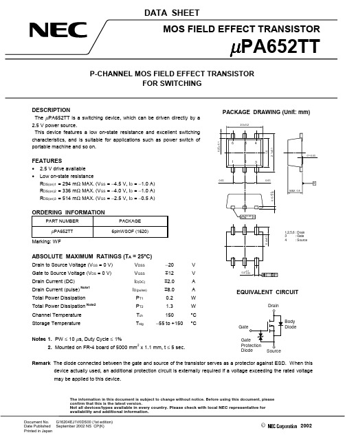
The information in this document is subject to change without notice. Before using this document, pleaseconfirm that this is the latest version.Not all devices/types available in every country. Please check with local NEC representative for availability and additional information.DATA SHEETDocument No.G16204EJ1V0DS00 (1st edition)Date Published September 2002 NS CP(K)Printed in Japan©2002DESCRIPTIONThe µPA652TT is a switching device, which can be driven directly by a 2.5 V power source.This device features a low on-state resistance and excellent switching characteristics, and is suitable for applications such as power switch of portable machine and so on.FEATURES• 2.5 V drive available •Low on-state resistanceR DS(on)1 = 294 m Ω MAX. (V GS = −4.5 V, I D = −1.0 A)R DS(on)2 = 336 m Ω MAX. (V GS = −4.0 V, I D = −1.0 A)R DS(on)3 = 514 m Ω MAX. (V GS = −2.5 V, I D = −0.5 A)ORDERING INFORMATIONPART NUMBERPACKAGE µPA652TT6pinWSOF (1620)Marking: WFABSOLUTE MAXIMUM RATINGS (T A = 25°C)Drain to Source Voltage (V GS = 0 V)V DSS −20V Gate to Source Voltage (V DS = 0 V)V GSS m 12V Drain Current (DC)I D(DC)m 2.0A Drain Current (pulse)Note1I D(pulse)m 8.0A Total Power Dissipation P T10.2W Total Power Dissipation Note2P T2 1.3W Channel Temperature T ch 150°C Storage TemperatureT stg−55 to +150°CNotes 1. PW ≤ 10 µs, Duty Cycle ≤ 1%2. Mounted on FR-4 board of 5000 mm 2x 1.1 mm, t ≤ 5 sec.Remark The diode connected between the gate and source of the transistor serves as a protector against ESD. When thisdevice actually used, an additional protection circuit is externally required if a voltage exceeding the rated voltage may be applied to this device.PACKAGE DRAWING (Unit: mm)EQUIVALENT CIRCUITBody DiodeDrainData Sheet G16204EJ1V0DS2ELECTRICAL CHARACTERISTICS (T A = 25°C)CHARACTERISTICSSYMBOL TEST CONDITIONSMIN.TYP.MAX.UNITZero Gate Voltage Drain Current I DSS V DS = −20 V, V GS = 0 V −10µA Gate Leakage Current I GSS V GS = m 12 V, V DS = 0 V m 10µA Gate Cut-off Voltage V GS(off)V DS= −10 V, I D = −250 µA −0.5−1.1−1.5V Forward Transfer Admittance | y fs |V DS = −10 V, I D = −1.0 A 1.02.4SDrain to Source On-state ResistanceR DS(on)1V GS = −4.5 V, I D = −1.0 A 235294m ΩR DS(on)2V GS = −4.0 V, I D = −1.0 A 252336m ΩR DS(on)3V GS = −2.5 V, I D = −0.5 A 385514m ΩInput Capacitance C iss V DS = −10 V 126pF Output CapacitanceC oss V GS = 0 V 47pF Reverse Transfer Capacitance C rss f = 1.0 MHz17pF Turn-on Delay Time t d(on)V DD = −10 V, I D = −1.0 A 28ns Rise Timet r V GS = −4.0 V 101ns Turn-off Delay Time t d(off)R G = 10 Ω80ns Fall Timet f 85ns Total Gate Charge Q G V DD = −16 V 1.1nC Gate to Source Charge Q GS V GS = −4.0 V 0.4nC Gate to Drain Charge Q GD I D = −2.0 A0.5nC Body Diode Forward VoltageV F(S-D)I F = 2.0 A, V GS = 0 V0.93VTEST CIRCUIT 2 GATE CHARGETEST CIRCUIT 1 SWITCHING TIME 0V LDDτ = 1 s µDuty Cycle ≤ 1%L DDData Sheet G16204EJ1V0DS3TYPICAL CHARACTERISTICS (T A = 25°C)DERATING FACTOR OF FORWARD BIAS SAFE OPERATING AREATOTAL POWER DISSIPATION vs.AMBIENT TEMPERATUREd T - Pe r c e n t a g e of R a t e d P o w e r -%T A - Ambient Temperature - °CP T - T o t a l P o w e r D i s s i p a t i o n - WT A - Ambient Temperature - °CFORWARD BIAS SAFE OPERATING AREAI D - D r a i n C u r r e n t - AV DS - Drain to Source Voltage - VTRANSIENT THERMAL RESISTANCE vs. PULSE WIDTHr t h (c h -A ) - T r a n s i e n t T h e r m a l R e s i s t a n c e - °C /WPW - Pulse Width - sData Sheet G16204EJ1V0DS4DRAIN CURRENT vs.DRAIN TO SOURCE VOLTAGEFORWARD TRANSFER CHARACTERISTICSI D - D r a i n C u r r e n t - AV DS - Drain to Source Voltage - VI D - D r a i n C u r r e n t - AV GS - Gate to Source Voltage - VGATE CUT-OFF VOLTAGE vs.CHANNEL TEMPERATUREFORWARD TRANSFER ADMITTANCE vs.DRAIN CURRENTV G S (o f f ) - G a t e C u t -o f f V o l t a g e - VT ch - Channel Temperature - °C| y f s | - F o r w a r d T r a n s f e r A d m i t t a n c e - SI D - Drain Current - ADRAIN TO SOURCE ON-STATE RESISTANCE vs.CHANNEL TEMPERATURE DRAIN TO SOURCE ON-STATE RESISTANCE vs.GATE TO SOURCE VOLTAGER D S (o n ) - D r a i n t o S o u r c e O n -s t a t e R e s i s t a n c e - m ΩT ch - Channel Temperature - °C R D S (o n ) - D r a i n t o S o u r c e O n -s t a t e R e s i s t a n c e - m ΩV GS - Gate to Source Voltage - VData Sheet G16204EJ1V0DS5DRAIN TO SOURCE ON-STATE RESISTANCE vs.DRAIN CURRENTDRAIN TO SOURCE ON-STATE RESISTANCE vs.DRAIN CURRENTR D S (o n ) - D r a i n t o S o u r c e O n -s t a t e R e s i s t a n c e - m ΩI D - Drain Current - AR D S (o n ) - D r a i n t o S o u r c e O n -s t a t e R e s i s t a n c e - m ΩI D - Drain Current - ADRAIN TO SOURCE ON-STATE RESISTANCE vs.DRAIN CURRENTSWITCHING CHARACTERISTICSR D S (o n ) - D r a i n t o S o u r c e O n -s t a t e R e s i s t a n c e - mΩI D - Drain Current - A t d (o n ), t r , t d (o f f ), t f - S w i t c h i n g T i m e - nsI D - Drain Current - ACAPACITANCE vs. DRAIN TO SOURCE VOLTAGESOURCE TO DRAIN DIODE FORWARD VOLTAGEC i s s , C o s s , C r s s - C a p a c it a n c e - p FV DS - Drain to Source Voltage - VI F - D i o d eF o r w a r d C u r r e n t - AV F(S-D) - Source to Drain Voltage - VData Sheet G16204EJ1V0DS6DYNAMIC INPUT/OUTPUT CHARACTERISTICSV G S - G a t e t o S o u r c e V o l t a g e - VQ G - Gate Change - nCData Sheet G16204EJ1V0DS 7[MEMO]M8E 00. 4The information in this document is current as of September, 2002. The information is subject to change without notice. For actual design-in, refer to the latest publications of NEC's data sheets or data books, etc., for the most up-to-date specifications of NEC semiconductor products. Not all products and/or types are available in every country. Please check with an NEC sales representative for availability and additional information.written consent of NEC. NEC assumes no responsibility for any errors that may appear in this document.NEC does not assume any liability for infringement of patents, copyrights or other intellectual property rights of third parties by or arising from the use of NEC semiconductor products listed in this document or any other liability arising from the use of such products. No license, express, implied or otherwise, is granted under any patents, copyrights or other intellectual property rights of NEC or others.Descriptions of circuits, software and other related information in this document are provided for illustrative purposes in semiconductor product operation and application examples. The incorporation of these circuits, software and information in the design of customer's equipment shall be done under the full responsibility of customer. NEC assumes no responsibility for any losses incurred by customers or third parties arising from the use of these circuits, software and information.While NEC endeavours to enhance the quality, reliability and safety of NEC semiconductor products, customers agree and acknowledge that the possibility of defects thereof cannot be eliminated entirely. To minimize risks of damage to property or injury (including death) to persons arising from defects in NEC semiconductor products, customers must incorporate sufficient safety measures in their design, such as redundancy, fire-containment, and anti-failure features.NEC semiconductor products are classified into the following three quality grades:"Standard", "Special" and "Specific". The "Specific" quality grade applies only to semiconductor products developed based on a customer-designated "quality assurance program" for a specific application. The recommended applications of a semiconductor product depend on its quality grade, as indicated below. Customers must check the quality grade of each semiconductor product before using it in a particular application."Standard":Computers, office equipment, communications equipment, test and measurement equipment, audioand visual equipment, home electronic appliances, machine tools, personal electronic equipment and industrial robots"Special":Transportation equipment (automobiles, trains, ships, etc.), traffic control systems, anti-disastersystems, anti-crime systems, safety equipment and medical equipment (not specifically designed for life support)"Specific":Aircraft, aerospace equipment, submersible repeaters, nuclear reactor control systems, lifesupport systems and medical equipment for life support, etc.The quality grade of NEC semiconductor products is "Standard" unless otherwise expressly specified in NEC's data sheets or data books, etc. If customers wish to use NEC semiconductor products in applications not intended by NEC, they must contact an NEC sales representative in advance to determine NEC's willingness to support a given application.(Note)(1)"NEC" as used in this statement means NEC Corporation and also includes its majority-owned subsidiaries.(2)"NEC semiconductor products" means any semiconductor product developed or manufactured by or for NEC (as defined above).••••••。
发电机组技术参数
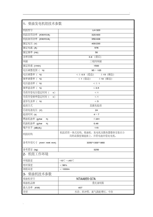
1、柴油发电机组技术参数机组型号LH-320机组常用功率(KW/KVA) 320/400机组备用功率(KW/KVA) 350/438额定电压(V) 400/230额定电流(A) 576额定频率(Hz) 50功率因数0.8(滞后)线制三相四线制额定转速(r/min) 1500电压调整范围(%)95~105电压调整率(%)≤±0.5(稳态)±15(瞬态)频率调整率(%)≤1(稳态)±10(瞬态)电压波动率(%)≤±1频率波动率(%)≤0.5负荷突变电压稳定时间(s)≤1负荷突变频率稳定时间(s)≤1波形失真率(%)≤5起动方式直流电起动启动电池电压(V) 24起动时间(s) 4~7燃油耗油率(g/kw·h) ≦201机油耗油率(g/kw·h) 0.48噪声水平(dB(A)) 115机组结构机组采用一体式结构,柴油机、发电机及散热器整体安装在公共的高强度钢底座上、并带电池补偿充电机。
参考外型尺寸(mm×mm×mm) 3350*1300*1860参考重量(kg) 32502、机组工作环境环境温度-10℃--+40℃相对湿度<98%海拔高度<1000m3、柴油机技术参数柴油机型号 NTAA855-G7A柴油机品牌重庆康明斯最大功率 (KW) 407类型水冷、四冲程、废气涡轮增压、中冷冷却方式自带风扇闭式循环冷却汽缸数量及排列方式6缸直列缸径(mm)×冲程(mm) 140*152压缩比18:1排烟温度(℃)(涡轮后) 520机油容量L 38润滑方式压力和飞溅润滑调速方式电调散热器管带式水箱4、发电机技术参数发电机型号 MP-350-4A/S发电机品牌马拉松额定功率(KW) 350励磁方式无刷自励(AVR)额定电压(V) 400/230额定频率(Hz) 50额定转速(r/min) 1500功率因数0.8(滞后)空气流量(m3/s) 1.0绝缘等级H防护等级IP23绕组节距2/3-(N°6)引线根数12超速能力2250min-1短路电流能力300%(3倍):10s电话干扰THF小于2% TIF小于50 5、机组其他简介用油标准符合国家标准0#、或-10#或-20#轻柴油符合国际标准15W-40CF4级机油测试所有机器在出货前经过严格的测试,并附有测试报告,报告中记录有详细的测试数据随机资料发动机零件目录、发动机使用及保养手册、发电机说明书、产品合格证。
PMC-851X综合保护测控装置用户说明书_V1.5_131014
855分油机面板操作说明

855分油机面板操作说明改变控制参数的一般说明:使用进入按钮:-进入参数单-进入参数-接受和储存一个新的参数值使用+或—按钮去改变显示窗口闪光的值设定合适参数过程说明如下:1)推ENTER参数NO1在参数程序单显示,通过参数单并设定参数。
2)当参数一旦设定,ENDI/O闪光显示,压+ STANDST现在在显示。
对于怎样设定排渣周期,看第3章,步骤程序,(在参数单小册子)。
注意:保证在操作以前操作者面板(绿灯)亮。
反复压+按钮可以阅读更多的操作资料,1)油的供给温度,正确的分离温度,参考系统安装说明小册子,TT1 98℃。
2)进口油压PT1 1.43)出口油压PT4 1.44)出口水压PT5 1.45)水传感器值MT 89℃6)速度 10300累计运行时间 5H参数设定:不同的系统和不同的条件在操作面板上参数的设定。
有三种型式的参数,安装,程序,和工厂设定的参数。
在安装时最初设定的参数,在运行期间根据需要也能设定程序参数。
参数在使用时不显示。
在小册子里的参数单对100和150分离设备是有效的。
一般说明;使用进入按钮:-进入参数单-进入参数-接受和储存一个新的参数值使用+或—按钮去改变显示窗口闪光的值改变参数步骤如下:1)推ENTER按钮,显示排渣时间P1 60, P1 是参数,60是设定值.2)推+按钮,直到显示你所希望参数数字,现在选择的数字在显示窗口闪光。
3)推进入按钮,选择在左边显示窗口参数,右边的参数值在闪光。
4)推+或—按钮去改变参数值。
5)推进入新参数被储存。
6)压+或—按钮,去改变下一个参数。
7)认可这一单子,在同一时间压+或--按钮,显示STANDST,或在运行时在左边触发值,同时剩余的排渣时间在右侧。
在EPC—50控制设备菜单中,可以显示以下单子:--安装参数--工厂参数--报警--试验对于详细资料看每一单子。
去打开菜单选择一个单子。
程序如下:1)推进入按钮,程序参数单现在打开2)压+的按钮,直到显示END3)在同一时间内推进入和+的按钮,安装在显示窗口闪光。
日本东芝光耦

日本东芝光耦深圳市美特光有限公司为日本东芝品牌光耦代理商。
TOSHIBA光耦中文名:东芝光耦。
东芝在日本东京都的总部大楼东芝(TOSHIBA),是日本最大的半导体制造商,亦是第二大综合电机制造商,隶属于三井集团旗下。
我司供应东芝全系列光耦合器,东芝光耦从功能分有逻辑输出,可控硅输出,光电二极管输出,固态继电器,高速输出,MOSFET输出,晶体管输出等。
高速光耦TLP115A描述:东芝光耦合器TLP115A是一个小外形耦合器,适合表面贴装。
TLP115A由一个高输出功率GAAℓAs发光二极管,光耦合到一个集成的高增益,高速光屏蔽检测器的输出是一个集电极开路肖特基钳位晶体管。
其中分capacirively加上常见的噪音到地面,提供1000V/μs的保证瞬变抗扰度规范。
特点:输入电流阈值:IF = 5mA (max.)切换速度:10MBD(典型值)共模瞬变抗扰度:± 1000V / μs (min.)最佳性能温度。
:0~70°C隔离电压:2500Vrms (min.)UL认证:UL1577, file no. E67349运用:高速,长距离隔离线路接收器微处理器系统接口数字隔离的A / D,D / A转换电脑外设接口接地回路消除参数:东芝高速光耦型号有:TLP550(F), TLP116A(E), 6N137F,TLP2166A(F), 6N136F,TLP2630(F),,TLP118(TPL,E),,TLP715(F),,TLP105(F), TLP108(F),,TLP557(F), 6N139(F), TLP719(TP,F), TLP2200F,6N138F,TLP559(IGM,F), TLP2309(E), TLP2631(F),TLP2098(F), TLP118(E), TLP558(F), TLP2601(F), TLP117(F), TLP718(F), TLP559(F), TLP2530(F), TLP2531(F), TLP2368(E), TLP512(F), TLP2105(F), TLP116(F), TLP2366(E), TLP115A(F), TLP716(F), TLP716(TP,F), TLP719(F), TLP714(F), TLP2118E(F), TLP2108(F),TLP2418(F), TLP2160(F), TLP2631TP1F TLP2168(F), TLP2355(E,TLP2362(E),TLP2200(TP1,F), 6N138(TP1,F), TLP2601(TP1,F), TLP2303(E TLP2303(TPR,ETLP109(IGM,E), TLP2468(F), TLP109(E), TLP2408(F), TLP104(E), TLP2409(F),TLP2358(E), TLP2301(TPL,E,TLP2303(TPL,E TLP555(F), TLP754(F), TLP2631(LF5,F), TLP2404(F), TLP2405(F), TLP2301(E,TLP2116(F), TLP2403(F), 6N137(TP1F),TLP116A(E,6N136(TP1F), TLP2630(TP1F), TLP2601(LF1,F), TLP104(TPR,E),TLP2362(TPR,E,TLP2531(TP1F), TLP2358(TPL,E), TLP2530(TP1F), TLP2116(TP,F), TLP2468(TP,F), 6N135(F), TLP559(IGM-TP5F), TLP2368(TPR,E,TLP2355(TPL,E,TLP751(F), TLP109(TPR,E), TLP2098(TPL,F), TLP2166A(TP,F), TLP118(TPR,E),TLP117(TPR,F), TLP2358(TPR,E), TLP2309(TPL,E), 6N139(TP1F), TLP109(IGM-TPR,E), TLP117(TPR,F),。
优仪高测温仪550说明书

优仪高测温仪550说明书感谢您选择优仪高公司的测试仪器。
为了让您能正确的使用本产品,使其达到最佳的运行状态和最长的使用寿命,我们随机配备了内容详尽的使用说明书,您可从中获取有关产品的技术参数,使用方法,注意事项等诸多方面的信息。
在您开始使用本产品前请先仔细阅读本说明书,如有不明之处,请及时与我们取得联系。
当涉及的内容有所变动时,恕不另行通知。
一、产品概述TD-3温度检测系统是本公司独立研发的兼顾科学技术和工程应用的高精度、高效率的热学检测平台。
是一套具有远程无线传输能力的可分布监测、集中管理的智能化温度记录及报警系统。
秉承了公司在业界的优良口碑和多年来在测试领域积累的技术精华。
采用了独特的设计理念,融合了先进测试原理使它完全超越了传统的测试仪器,代表了温度检测的最新发展方向。
无论在何种苛刻的测试环境下,都会有出类拔萃的表现。
该系统由系统主控机,终端测温仪及功能完备的上位机管理软件组成。
具有精度高、响应速度快、操作灵活,界面直观,组网方便,抗干扰性强等优良特性。
是工程测试人员的理想选择。
被广泛用于大专院校、科研单位、检测单位以及冶金、建筑、桥梁、水电等领域对温度的检测。
二、技术参数(1)测量范围:-55℃~+125℃(2)精度:士0.5℃(-20℃~+80℃)(3)分辨率:0.1℃(4)采样点数:小于65536(5)巡检周期:大于10s(6)报警阈值:-55℃~+125℃(7)数据输出:LCD彩屏/PC(8)无线频段:433MHz(ISM)(9)传输技术:直接序列扩频(DSSS)(10)传输距离:小于1500m(11)测点线长:小于100m(12)供电方式:AC220V/内置锂电池(13)电池续航:48h (14)通信接口:RS232(15)电池寿命:3~5年(16)额定功率:25W(17)工作温度:-10℃~+80℃(18)工作湿度:小于90%RH(19)主机尺寸:260mm×206mm×106mm(20)从机尺寸:333mm×236mm×126mm三.操作方法测试前期准备工作请依据国家规范或其他相关行业标准实施。
851-283 Rev. C 顶部挂载驱动包设备安装、运行和维护手册 6100系列大负载90°卫生机
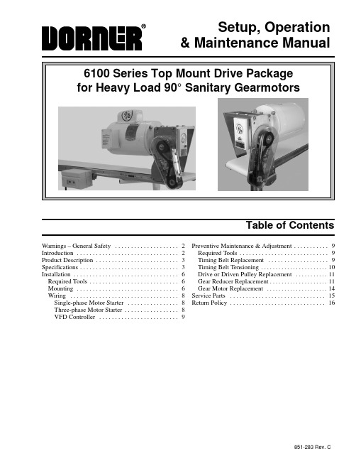
Setup, Operation& Maintenance ManualTable of ContentsWarnings – General Safety2. . . . . . . . . . . . . . . . . . . . Introduction2 . . . . . . . . . . . . . . . . . . . . . . . . . . . . . . . .Product Description3. . . . . . . . . . . . . . . . . . . . . . . . . .Specifications3. . . . . . . . . . . . . . . . . . . . . . . . . . . . . . .Installation6 . . . . . . . . . . . . . . . . . . . . . . . . . . . . . . . . . Required Tools6. . . . . . . . . . . . . . . . . . . . . . . . . . . . Mounting6 . . . . . . . . . . . . . . . . . . . . . . . . . . . . . . . .Wiring8 . . . . . . . . . . . . . . . . . . . . . . . . . . . . . . . . . .Single-phase Motor Starter8. . . . . . . . . . . . . . . .Three-phase Motor Starter8. . . . . . . . . . . . . . . . .VFD Controller9. . . . . . . . . . . . . . . . . . . . . . . . . Preventive Maintenance & Adjustment9. . . . . . . . . . . Required Tools9. . . . . . . . . . . . . . . . . . . . . . . . . . . . Timing Belt Replacement9. . . . . . . . . . . . . . . . . . . Timing Belt Tensioning10. . . . . . . . . . . . . . . . . . . . . . . Drive or Driven Pulley Replacement11. . . . . . . . . . . Gear Reducer Replacement11. . . . . . . . . . . . . . . . . . . . Gear Motor Replacement14. . . . . . . . . . . . . . . . . . . . . Service Parts15. . . . . . . . . . . . . . . . . . . . . . . . . . . . . . Return Policy16. . . . . . . . . . . . . . . . . . . . . . . . . . . . . .851-283 Rev. C6100 Series Top Mount Drive Package for Heavy Load 90° Sanitary Gearmotors Setup, Operation & Maintenance Manual 851-283 Rev. C 2Dorner Mfg. Corp.IntroductionIMPORTANT: Some illustrations may showguards removed. Do NOT operate equipment with-out guards.Upon receipt of shipment:D Compare shipment with packing slip. Contact facto-ry regarding discrepancies.D Inspect packages for shipping damage. Contact carrier regarding damage.D Accessories may be shipped loose. See accessory in-structions for installation.Dorner 6100 Series conveyors are covered by patent number 5174435 and corresponding patents and patent applications in other countries.Dorner ’s Limited Warranty applies.Dorner reserves the right to make changes at any time without notice or obligation.Warnings – General Safety6100 Series Top Mount Drive Package for Heavy Load 90° Sanitary Gearmotors Setup, Operation & Maintenance Manual Dorner Mfg. Corp.3851-283 Rev. CRefer to Figure 1 for typical components.A ConveyorB Mounting BracketC GearmotorD Timing Belt TensionerE CoverF Timing BeltG Drive PulleyH Driven Pulley IMotor ControlTypical ComponentsDFigure 1EAGIFCSpecificationsGearmotor Mounting Package Models:Example:R = Right HandDrive/Driven Pulleys (See tables 2, 3 & 4)= Flat Belt (or add cleat type)* See “Ordering and Specifications ” Catalog for details.Table 1: Gearmotor SpecificationsTable 2: Heavy Load Fixed Speed 905 Sanitary 60 Hz Gearmotors(vp) = Voltage and Phase(r) = Output Shaft Orientation11 = 115 V, 1 phase L = Left Hand23 = 208–230/460 V, 3 phase R = Right Hand43 = 460V, 3 phaseTable 3: Heavy Load Variable Speed 905 Sanitary VFD Gearmotors(r) = Output Shaft OrientationL = Left HandR = Right Hand6100 Series Top Mount Drive Package for Heavy Load 90° Sanitary Gearmotors Setup, Operation & Maintenance Manual 851-283 Rev. C4Dorner Mfg. Corp.Table 4: Heavy Load Variable Speed 905 Sanitary DC Gearmotors(r) = Output Shaft OrientationL = Left HandR = Right HandNOTE: For belt speed other than those listed,contact factory for details.6100 Series Top Mount Drive Package for Heavy Load 90° Sanitary Gearmotors Setup, Operation & Maintenance Manual Dorner Mfg. Corp.5851-283 Rev. C6100 Series Top Mount Drive Package for Heavy Load 90° Sanitary Gearmotors Setup, Operation & Maintenance Manual 851-283 Rev. C 6Dorner Mfg. Corp.Required ToolsD Wrenches (for hexagon head fasteners)8mm, 10mm, 13mm & 14mm D 2.5 mm hex key wrench D Straight edge D Torque wrenchMounting1.Gather components (Figure 2)NOTE: 4” (102mm) and wider mounting assemblyshown. 2” (51mm) and 3” (76mm) wide mounting assemblies include two spacer tubes (AC of Figure 5) and two long M6 screws (AD).Figure 2AIHJGFKNM2.Remove screws (O of Figure 3) from both sides ofconveyor.Figure 3ONO3.Install square key (N of Figure 3) into drive shaft.4a.For 4” (102mm) and wider conveyors, loosen (but donot remove) screws (P of Figure 4). Attach top mount assembly (A) to conveyor with screws (B). Tighten screws (B) and (P) to 92 in-lb (10.4 Nm).Figure 4PBInstallation6100 Series Top Mount Drive Package for Heavy Load 90° Sanitary Gearmotors Setup, Operation & Maintenance Manual Dorner Mfg. Corp.7851-283 Rev. C4b.For 2” (51mm) and 3” (76mm) wide conveyors,loosen (but do not remove) screws (P of Figure 5).Attach top mount assembly (A) to conveyor with screws (B), spacer tubes (AC) and screws (AD).Tighten screws (B) and (P) to 92 in-lb (10.4 Nm).Figure 5BAC5.Wrap timing belt (C of Figure 6) around drivenpulley (D) and drive pulley (H). Attach driven pulley (D) to conveyor shaft.Figure 6DCHing a straight edge (Q of Figure 7), align drivenpulley (D) with drive pulley (H). Tighten driven pulley set screws (R).Figure 7QDR H7.Depending on conveyor belt travel (1 or 2 of Figure8), locate timing belt tensioner (S), as shown.Tension timing belt to obtain 1/8¨ (3 mm) deflectionfor 1 lb (4.3 N) of force at timing belt mid-point (T). Tighten tensioner to 38 ft-lb (51 Nm).Figure 81SST8.Attach cover (E of Figure 9) with screws (U).Tighten screws to 35 in-lb (4 Nm).Figure 9EU9.Install key (F of Figure 10).Figure 10FGIMPORTANT:Be extremely careful when couplingmotor to gear reducer. Avoid misalignment and forcing the connection causing possible permanent gear reducer seal damage.Installation6100 Series Top Mount Drive Package for Heavy Load 90° Sanitary Gearmotors Setup, Operation & Maintenance Manual 851-283 Rev. C 8Dorner Mfg. Corp.10.Attach gear motor (I of Figure 11) to gear reducer (J)with screws and washers (G of Figure 10). Tighten to 32 ft-lb (41 Nm).Figure 11JIGG11.Attach mounting clips (M of Figure 12) to conveyor.Figure 12M NOTE: Three-phase Motor Starter shown,Single-phase Starter similar. For VFD controller mounting, see accessory instructions.12.Attach motor starter (K of Figure 13) to clips withscrews (L). Tighten to 92 in-lb (10.4 Nm).Figure 13KLLWiringSingle-phase Motor StarterNOTE: Power cord must be plugged into a GFI out-let. No additional wiring is required.Three-phase Motor StarterNOTE: 230 volt three-phase manual motor startersmust be wired in accordance with applicable electrical codes.1.Loosen cover screws (V of Figure 14) and removecover.Figure 14WVVNOTE: Line cord must be 0.28¨ (7 mm) minimum to0.47¨ (12 mm) maximum in diameter.2.Insert line cord through grip (W) and tighten nut.3.For correct three-phase motor shaft rotation, con-nect line phase sequence L1, L2 & L3 to terminals as shown (Figure 15).InstallationInstallationEUFigure 166100 Series Top Mount Drive Package for Heavy Load 90° Sanitary Gearmotors Setup, Operation & Maintenance Manual Dorner Mfg. Corp.9851-283 Rev. C6100 Series Top Mount Drive Package for Heavy Load 90° Sanitary Gearmotors Setup, Operation & Maintenance Manual 851-283 Rev. C 10Dorner Mfg. Corp.2.Loosen tensioner (S of Figure 17).Figure 17CSH3.Remove timing belt (C).NOTE: If timing belt does not slide over pulleyflange, loosen driven pulley set screws (R of Figure 18) and remove pulley with belt. For re-installation,see steps 5 and 6 on page 7.Figure 18DCHR4.Install new timing belt.5.Depending on conveyor belt travel (1 or 2 of Figure19), locate timing belt tensioner (S) as shown.Tension timing belt to obtain 1/8¨ (3 mm) deflection for 1 lb (4.3 N) of force at timing belt mid-point (T). Tighten tensioner to 38 ft-lb (51 Nm).Figure 191SSTNOTE: Do not over-tighten screws (U of Figure 20).6.Attach cover (E of Figure 20) and tighten four (4)screws (U) to 35 in-lb (4 Nm).Figure 20EUTiming Belt Tensioning1.Remove four (4) screws (U of Figure 21) and removecover (E).Preventive Maintenance & Adjustment6100 Series Top Mount Drive Package for Heavy Load 90° Sanitary Gearmotors Setup, Operation & Maintenance Manual Dorner Mfg. Corp.11851-283 Rev. CFigure 21EU2.Loosen tensioner (S of Figure 22).Figure 22C SH3.Depending on direction of conveyor belt travel (1 or2 of Figure 23), position belt tensioner (S) as shown.Tension belt to obtain 1/8¨ (3 mm) deflection for 1.0lb (456 grams) of force at belt mid-point (T). Tighten tensioner screw to 103 in-lb (12 Nm).Figure 2312STST4.Attach cover (E of Figure 21) with four (4) screws(U). Tighten to 35 in-lb (4 Nm).Drive or Driven Pulley Replacementplete steps 1 through 3 of “Timing BeltReplacement ” section on page 10.2.Loosen set screws and remove drive or driven pulley.NOTE: If drive pulley (H of Figure 22) is replaced,wrap timing belt around drive pulley and complete step 3.plete steps 5 through 8 of “Installation ” sectionon page 7.Gear Reducer Replacement1.Remove four (4) screws (U of Figure 24) and removecover (E).Figure 24EU6100 Series Top Mount Drive Package for Heavy Load 90° Sanitary Gearmotors Setup, Operation & Maintenance Manual 851-283 Rev. C 12Dorner Mfg. Corp.2.Loosen tensioner (S of Figure 25).Figure 25C SH3.Loosen drive pulley set screws (X of Figure 26).Remove drive pulley (H) and timing belt (C).Figure 26XCH4.Remove screws and washers (G of Figure 27).Detach motor (I) from gear reducer (J).GGFigure 27JI5.Remove four (4) gear reducer mounting screws (Z ofFigure 28). Remove gear reducer (J).Figure 28JZZ6.Attach new gear reducer to top mount with screws(Z).IMPORTANT: Be extremely careful whencoupling motor to gear reducer. Avoid misalignment and forcing the connection causing possible permanent gear reducer seal damage.7.With key (F of Figure 29) in keyway, slide motor (I)and gear reducer (J) together. Install screws (G) and tighten.Figure 29IJGGF6100 Series Top Mount Drive Package for Heavy Load 90° Sanitary Gearmotors Setup, Operation & Maintenance Manual Dorner Mfg. Corp.13851-283 Rev. C8.Wrap timing belt (C of Figure 30) around drivepulley (H) and driven pulley (D). Attach drive pulley (H) to gear reducer shaft.Figure 30XCHDing a straight edge (Q of Figure 7), align drivepulley (H) with driven pulley (D). Tighten drive pulley set screws (X).Figure 31QDR H10.Depending on conveyor belt travel (1 or 2 of Figure32), locate timing belt tensioner (S), as shown.Tension timing belt to obtain 1/8¨ (3 mm) deflection for 1 lb (4.3 N) of force at timing belt mid-point (T). Tighten tensioner to 38 ft-lb (51 Nm).Figure 3212SST11.Attach cover (E of Figure 33) with screws (U).Tighten screws to 35 in-lb (4 Nm).Figure 33EU6100 Series Top Mount Drive Package for Heavy Load 90° Sanitary Gearmotors Setup, Operation & Maintenance Manual 851-283 Rev. C 14Dorner Mfg. Corp.Motor Replacement1.Loosen terminal box screws (AA of Figure 34) andremove cover (AB).Figure 34ABAAAA2.Record incoming wire colors. Loosen wire nuts andremove wires.3.Loosen cord grip and remove cord.4.Remove screws and washers (G of Figure 35).Detach motor (I) from gear reducer (J). Retain motor output shaft key (F).Figure 35IJGFIMPORTANT: Be extremely careful whencoupling motor to gear reducer. Avoid misalignment and forcing the connection causing possible permanent gear reducer seal damage.5.With key (F of Figure 36) in keyway, slide new gearmotor and gear reducer (J) together. Install screws and washers (G) and tighten.Figure 36JG GF6.To replace wiring, reverse steps 1, 2 and 3 on thispage.6100 Series Top Mount Drive Package for Heavy Load 90° Sanitary Gearmotors Setup, Operation & Maintenance Manual Dorner Mfg. Corp.15851-283 Rev. CNOTE: For replacement parts other than thoseshown on this page, contact an authorized Dorner Service Center or the factory.Figure 3768753214851-283 Rev. CPrinted in U.S.A.200For replacement parts, contact an authorizedDorner Service Center or the factory.Return Policy。
Eaton 5E 850 VA USB UPS 产品说明说明书

Eaton 5E850IUSBUSB UPS Eaton 5E, 850 VA, 480 W, Ingresso: C14, Uscite: (4)C13, towerGeneral specificationsUPS Eaton 5E5E850IUSB743172047588288 mm148 mm100 mm5.16 kg Con marchio CEcULus ListedIEC 62040-2 C1-C2 / EN 55024 / CISPR22, Classe B / FCC, Parte 15, Classe BIEC/EN 62040-1IEC/EN 62040-2EACCE EMEA e GLOBALENome prodotto Sigla catalogoUPC Lunghezza/profondità del prodotto Altezza prodotto Larghezza prodottoPeso prodotto ConformitàCertificazione/i Note catalogo60 Hz480 WtorreNoC14162 V280 V50 HzEaton UPS Companion (consente l’arresto sicuro del sistema, la misurazione del consumo energetico e la configurazione delle impostazioni dell’UPS)Sigillata, piombo-acido95EU declaration of conformity Eaton 5E UPS Eaton 5E UPS - Installation and user manualFrequenza secondaria - max PotenzaFattore di formaInclude scheda di rete Connessione di ingresso Tensione di ingresso - min Tensione di uscita - max Frequenza secondaria - max Compatibilità softwareTipo di batteriaEfficienzaCaratteristiche speciali Compliance information Guide utenteRegolazione automatica della tensione (AVR) Permette di risparmiare spazio grazie al design compattoPorta USB conforme HID, per l’integrazione automatica con i principali sistemi operativi (Windows/Mac OS/Linux) Protezione della linea dati per garantire che la linea internet (compresa xDSL)sia protetta dallesovratensioniTipo di costruzioneModello indipendenteTensione di uscita - min170 VColoreneroCapacità batteria estesaNoRange di tensione in uscita170-280 VTopologiaLine-InteractiveProtezione da sovratensioneSìTempo di funzionamento a metà carico5 minTensione nominale di ingresso230 V predefinita (220/230/240 V)Campo di frequenza di ingresso45-63 HzTensione di ingresso - max290 VTipo di tensioneCAFase (uscita)1Gestione della batteriaTest automatico della batteria, protezione contro le scariche profonde, possibilità di avviamento a freddoFunzione di autospegnimentoSìNumero di uscite C134Temperatura di esercizio - Min0 °CValori nominali VA850 VAContatto di commutazione privo di potenziale NoPresa(4) C13Fase (ingresso)1Contenuto della confezione(2) Cavi di uscita IEC-IECManuale d'usoLivello di rumoreMeno di 40 dB a 1 metroTipo di alimentazione1Grafico runtimeVisualizza il grafico di runtimeInterfaccia utenteLEDQuantità della Batteria1Temperatura di esercizio - Max40 °CTensione230 VIntervallo di temperaturaDa 0°C a 40°CInterfaccia EthernetNoComunicazionePorta USB (conforme HID)Umidità relativa0-90% senza condensaPotenza apparente in uscita850 VAKit di montaggio rackNoEaton Corporation plcEaton House30 Pembroke RoadDublin 4, Ireland © 2023 Eaton. Tutti i diritti riservati. Eaton is a registered trademark.All other trademarks areproperty of their respectiveowners./socialmedia 50/60 Hz30 secUSB45 Hz12 V/9 AhGruppo di continuità230 VN°162-290 V50/60 Hz63 Hz2000 mFrequenza di uscitaRuntime a pieno caricoTipo di interfacciaFrequenza primaria - MinClassificazione batteriaTipoTensione nominale di uscitaSlot di espansioneRange di tensione in ingressoFrequenza nominaleFrequenza primaria - MaxAltitudine。
雷达恢弘制造公司 RE8530 2英寸 WJ 家庭增强抬高系统安装指南说明书

RUBICON MANUFACTURING INC. 3290 MONIER CIR., RANCHO CORDOVA, CA. 95742 916-473-4600 INSTALLATION INSTRUCTIONS FOR: RE8530 2” WJ BUDGET BOOST SUSPENSION LIFTSafety Warning:Suspension systems or components that enhance the off-road performance of your vehicle may cause it to handle differently, on and off-road, than it did from the factory. Care must be taken to prevent loss of control or vehicle rollover during sudden maneuvers. Failure to drive the vehicle safely may result in serious injury or death to driver and passengers. We recommend you always wear your seatbelt, drive safely and avoid quick turns and other sudden maneuvers. Constant maintenance is required to keep your vehicle safe. Thoroughly inspect your vehicle before and after every off-road use.Installation Warning:We recommend that certified technicians perform the installations of our products. Attempts to install these products without knowledge or experience may jeopardize the safety of the vehicle. These instructions only cover the installation of our products and may not include factory procedures for disassembly and reassembly of factory components. Read instructions from start to finish and be sure all parts are present before disassembling the vehicle. Included instructions are guidelines only for recommended procedures and in no way are meant to be definitive. Installer is responsible to insure a safe and controllable vehicle after performing modifications. Do not perform test drives on public roads with partially completed installations. Always double and triple check your work before use.KIT CONTENTS:2 RXT2420 Rear shocks2 RXT2421 Front shocks1 RE1335 Front coil spring spacers, pair1 RE1336 Rear coil spring spacers, pair1 RE1392 Front bump stop spacers1 RE1393 Rear bump stopsREQUIRED TOOLS:Basic mechanics' hand toolsJack stands and floor jackSpring compressor (optional)NOTE: A coil spring compressor will assist in an easierremoval and installation of the coil springs.REAR INSTALLATION:1.Support the vehicle chassis, axle housing, and remove rear wheels.2.Remove old shocks.3.Disconnect rear sway bar end links.4.Lower rear axle assembly and remove rear factory coils.5.Install RE1393 rear bump spacers on to the factory coil locatingextension using the supplied self-taping hardware. (See photo 1)6.Install coil spring spacers with radius side down (see photo 2).7.Install rear coil springs.8.Raise the axle housing and reconnect rear sway bar end links. 9.Install the supplied sleeves into the rear shocks. Short sleeve in thebody end and the long sleeve in the shaft end. Install rear shockswith the body down.10.Install rear wheels.FRONT INSTALLATION:11.Support the vehicle chassis, axle housing, and remove front wheels.12.Remove old shocks.13.Disconnect front sway bar end links.14.Remove factory rubber bump stops and cups.15.Reinstall the cups with the RE1392 extensions between the framerail and the cup using the supplied longer hardware.16.Reinstall the factory rubber bump stop. (See photo 3)17.Lower front axle assembly and remove front factory coils.18.Remove rubber coil spring isolators.19.Install coil spring spacer between frame and rubber spring isolatorwith lip down (see photo 4).20.Install coil springs.21.Install the new front shocks. Supplied bar pins will need to be putthrough the bottom shock eyes (use light grease).22.Raise the axle assembly back into place and reinstall the front swaybar links.23.Torque any previously removed factory hardware to factory specs.24.Align vehicle as soon as practical to minimum factory caster andmaximum factory toe-in specifications.25.Recheck all bolts after 50 miles and again after every off roadexcursion.PHOTO 1PHOTO 2PHOTO 3Photo 4TROUBLESHOOTINGREAR DRIVELINE:Acceleration vibration: Caused by the pinion being too high in relation to the transfer case output shaft. Adjust pinion angle per factory manual accordingly.Deceleration vibration: Caused by the pinion being too low in relation to the transfer case output shaft. Adjust pinion angle per factory manual accordingly.Slip yoke vibration: Caused by excessive angle on the transfer case slip yoke - common on vehicles with lifts. This can usually be cured on 1.5”-3.5” lifts with a transfer case drop kit. Note that pinion adjustment may also be required - see acceleration and deceleration vibration troubleshooting above.HIGH SPEED WOBBLE:This is fairly common with y-type steering on lifted ZJ's. It is a condition where front tires will shimmy after hitting a bump. Avoid bias ply tires and wheels with excessive offset. Check for worn or loose parts. In most cases a reduction of positive castor will eliminate this condition. A good rule of thumb is minimum factory caster and maximum factory toe in. Note that lift heights increased with coil spacers (or taller coils) may exhibit wobble that cannot be corrected with alignment.BUMP STEER:Caused by improper relationship of drag link and track bar. To correct, center axle again following the instructions supplied with the track bar. Next determine the neutral position of the steering wheel. Adjust the drag link to center the steering wheel.。
康明斯船用主机数据单NTA855-M350
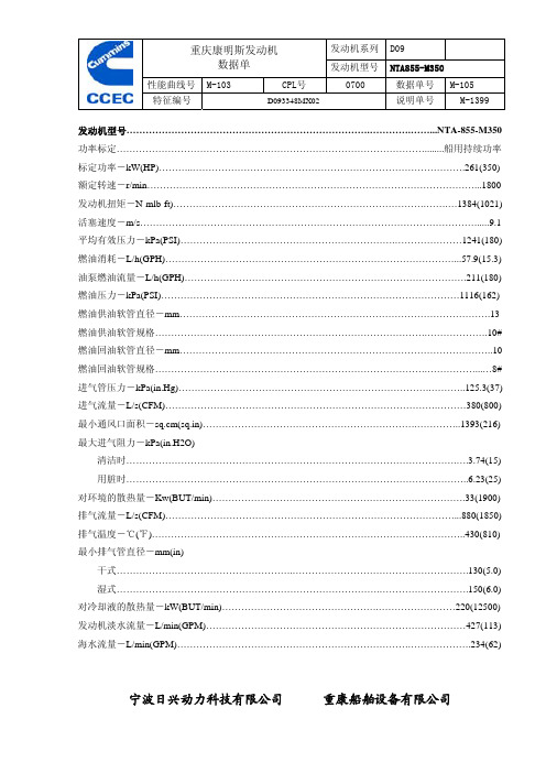
发动机系列D09重庆康明斯发动机 数据单发动机型号NTA855-M350 性能曲线号 M-103CPL号 0700 数据单号 M-105 特征编号 D093348MX02 说明单号 M-1399宁波日兴动力科技有限公司 重康船舶设备有限公司发动机型号………………………………………………………………….………….……...NTA-855-M350 功率标定……………………………………………………………………………………........船用持续功率 标定功率-kW(HP)………..………………………………………………………………………….261(350) 额定转速-r/min…………………………………………………………………………………………...1800 发动机扭矩-N-mlb-ft)…………………………………………………………………….…….…1384(1021) 活塞速度-m/s…………………………………………………………………………………………….....9.1 平均有效压力-kPa(PSI)………………………………………………………….…………………1241(180) 燃油消耗-L/h(GPH)………………………………………………………………………………...57.9(15.3) 油泵燃油流量-L/h(GPH)…………………………………………………………………………….211(180) 燃油压力-kPa(PSI)…………………………………………………………………………………1116(162) 燃油供油软管直径-mm…………………………………………………………………………………….13 燃油供油软管规格………………………………………………………………………….……………….10#燃油回油软管直径-mm……………………………………………………………………………………..10 燃油回油软管规格………………………………………………………………………….……………...…8# 进气管压力-kPa(in.Hg)…………………………………………………………………….………..125.3(37) 进气流量-L/s(CFM)………………………………………………………………………….………380(800) 最小通风口面积-sq.cm(sq.in)………………………………………………………….…………..1393(216) 最大进气阻力-kPa(in.H2O)清洁时………………………………………………………………………………………….….3.74(15) 用脏时……………………………………………………………………………………………..6.23(25) 对环境的散热量-Kw(BUT/min)…………………………………………………………………….33(1900) 排气流量-L/s(CFM)………………………………………………………………………………...880(1850) 排气温度-℃(℉)……………………………………………………………………………………..430(810) 最小排气管直径-mm(in)干式……………………………………………….……………………………………………….130(5.0) 湿式……………………………………………………………………….……………………….150(6.0) 对冷却液的散热量-kW(BUT/min)………………………………………….……………………220(12500) 发动机淡水流量-L/min(GPM)………………………………………………………………………427(113) 海水流量-L/min(GPM)……………………………………………………………….……………….234(62)。
佳谱手持光谱仪的技术参数仪

佳谱手持光谱仪的技术参数仪
佳谱手持光谱仪是一种便携式的光谱分析仪器,它的技术参数如下:- 探测器:高性能Sipin探测组件。
- 激发源:45KV/200uA-银靶/钨靶端窗一体化微型X射线光管及高压源。
- 元素检测范围:原子序数为20~92(钙至铀之间)的元素,以及分析合金中的主要元素Ti,V,Cr,Mn,Fe,Co,Ni,Cu,Zn,Zr,Nb,Mo,Ag,Cd,Sn,Sb,Ta,W,Pb,Bi共20个(可继续添加)。
- 检测对象:固体。
- 分析方法:直读分析法+基本参数法(FP)。
- 软件:具有数据分析、谱图显示、报告打印等功能,并且可以实现数据多平台(仪器,PC端,手机端,云端)同步,具有通过电子邮件发送分析报告的功能。
- 重量:≤1.75KG(含电池)。
- 微电脑显示系统:半透半反工业级定制触摸屏≥5英寸,分辨率1080*720。
- 电源:可充电锂电池,标配6800mAh,电压7.2V;可持续工作达12小时。
- 充电模式:通用适配器充流供电。
- 准直器、滤光片:特殊防辐射材料准直器,内径3MM;无滤光片,省去切换时间,软件扣除本底干扰。
- 前端测试窗口:≤9mm*5mm“腰”型窗口。
手持光谱仪具有操作简单、快速、准确等优点,在合金分析、矿石勘探、环境监测等领域有广泛的应用。
- 1、下载文档前请自行甄别文档内容的完整性,平台不提供额外的编辑、内容补充、找答案等附加服务。
- 2、"仅部分预览"的文档,不可在线预览部分如存在完整性等问题,可反馈申请退款(可完整预览的文档不适用该条件!)。
- 3、如文档侵犯您的权益,请联系客服反馈,我们会尽快为您处理(人工客服工作时间:9:00-18:30)。
Test Conditions VCB = 5 V, IE = 0 mA VEB = 1 V, IC = 0 mA VCE = 1 V, IC = 10 mA VCE = 1 V, IC = 10 mA, f = 2 GHz
MIN. − − 70 10.0 7.0 − −
TYP. − − − 12.0 9.0 1.5 0.4
REVERSE TRANSFER CAPACITANCE vs. COLLECTOR TO BASE VOLTAGE
Reverse Transfer Capacitance Cre (pF)
0.5 f = 1 MHz 0.4
1.0 f = 1 MHz 0.8
0.3
0.6
0.2
0.4
0.1
0.2
0
1
2
TOTAL POWER DISSIPATION vs. AMBIENT TEMPERATURE
300 Total Power Dissipation Ptot (mW) 250 200
190 210
Mounted on Glass Epoxy PCB (1.08 cm2 × 1.0 mm (t) ) 2 Elements in total Q2
ELECTRICAL CHARACTERISTICS (TA = +25°C) (1) Q1
Parameter Collector Cut-off Current Emitter Cut-off Current DC Current Gain Gain Bandwidth Product Insertion Power Gain Noise Figure Reverse Transfer Capacitance Symbol ICBO IEBO hFE
hFE CLASSIFICATION
Rank Marking hFE Value of Q1 hFE Value of Q2 FB vN 70 to 140 100 to 145
Data Sheet PU10098EJ01V0DS
3
µPA855TD
TYPICAL CHARACTERISTICS (Unless otherwise specified, TA = +25°C)
0.7
0.8
0.9
1.0
Collector Current IC (mA)
0.0001 0.4
0.5
0.6
0.7
0.8
0.9
1.0
Base to Emitter Voltage VBE (V)
Base to Emitter Voltage VBE (V)
COLLECTOR CURRENT vs. BASE TO EMITTER VOLTAGE
µPA855TD µPA855TD-T3
Remark To order evaluation samples, contact your nearby sales office. The unit sample quantity is 50 pcs.
Because this product uses high-frequency technology, avoid excessive static electricity, etc.
80 70 500 µ A 450 µ A 400 µ A 350 µ A 300 µ A 250 µ A 200 µ A 150 µ A 100 µ A IB = 50 µ A
Collector Current IC (mA)
30 25 20 15 10 5 0
350 µ A
Collector Current IC (mA)
100 10 1 0.1 0.01 0.001 VCE = 1 V 100 10 1 0.1 0.01 0.001
COLLECTOR CURRENT vs. BASE TO EMITTER VOLTAGE
VCE = 1 V
Collector Current IC (mA)
0.0001 0.4
0.5
0.6
MAX. 100 100 140 − − 2.0 0.7
Unit nA nA − GHz dB dB pF
fT S21e NF Cre
Note 2 2
VCE = 1 V, IC = 10 mA, f = 2 GHz VCE = 1 V, IC = 3 mA, f = 2 GHz, ZS = Zopt VCB = 0.5 V, IE = 0 mA, f = 1 MHz
150 100
90
Q1 50
0
25
50
75
100
125
150
Ambient Temperature TA (˚C)
Q1
Q2
REVERSE TRANSFER CAPACITANCE vs. COLLECTOR TO BASE VOLTAGE
Reverse Transfer Capacitance Cre (pF)
DATA SHEET
NPN SILICON RF TWIN TRANSISTOR
µPA855TD
NPN SILICON RF TRANSISTOR (WITH 2 DIFFERENT ELEMENTS) IN A 6-PIN LEAD-LESS w voltage operation • 2 different built-in transistors (2SC5737, 2SC5745) Q1: Low noise transistor NF = 1.5 dB TYP. @ VCE = 1 V, IC = 3 mA, f = 2 GHz Q2: Low phase distortion transistor suited for OSC operation fT = 5.5 GHz TYP., S21e2 = 4.5 dB TYP. @ VCE = 1 V, IC = 10 mA, f = 2 GHz • 6-pin lead-less minimold package
BUILT-IN TRANSISTORS
Q1 3-pin thin-type ultra super minimold part No. 2SC5737 Q2 2SC5745
ORDERING INFORMATION
Part Number Quantity 50 pcs (Non reel) 10 kpcs/reel Supplying Form • 8 mm wide embossed taping • Pin 1 (Q1 Collector), Pin 6 (Q1 Base) face the perforation side of the tape
4
250 µ A 200 µ A 150 µ A 100 µ A IB = 50 µ A
60 50 40 30 20 10 0 1 2 3
1
2
3
4
5
6
7
Collector to Emitter Voltage VCE (V)
Collector to Emitter Voltage VCE (V)
(2) Q2
Parameter Collector Cut-off Current Emitter Cut-off Current DC Current Gain Gain Bandwidth Product Insertion Power Gain Noise Figure Reverse Transfer Capacitance Symbol ICBO IEBO hFE
Note
Ratings Q2 15 5.5 1.5 100 190
Unit
5 3 2 30 90
V V V mA mW °C °C
210 in 2 elements Junction Temperature Storage Temperature Tj Tstg 150 −65 to +150
2 Note Mounted on 1.08 cm × 1.0 mm (t) glass epoxy PCB
MAX. 100 100 145 − − 3.0 0.85
Unit nA nA − GHz dB dB pF
fT S21e NF Cre
Note 2 2
VCE = 1 V, IC = 10 mA, f = 2 GHz VCE = 1 V, IC = 10 mA, f = 2 GHz, ZS = Zopt VCB = 0.5 V, IE = 0 mA, f = 1 MHz
5
µPA855TD
Q1 Q2
COLLECTOR CURRENT vs. COLLECTOR TO EMITTER VOLTAGE
40 35 500 µ A 450 µ A 400 µ A 300 µ A
COLLECTOR CURRENT vs. COLLECTOR TO EMITTER VOLTAGE
Notes 1. Pulse measurement: PW ≤ 350 µs, Duty Cycle ≤ 2% 2. Collector to base capacitance when the emitter grounded
2
Data Sheet PU10098EJ01V0DS
µPA855TD
Document No. PU10098EJ01V0DS (1st edition) Date Published March 2002 CP(K) Printed in Japan
© NEC Compound Semiconductor Devices 2002
µPA855TD
ABSOLUTE MAXIMUM RATINGS (TA = +25°C)
