FIBOCOM_G510 LCC SMT应用设计说明_V2.0.0
TH9520 磁性元器件综合分析系统使用说明书

使用说明书OPERATION MANUALTH9520集成化磁性元器件综合分析系统TH9520 MAGNETIC COMPONENTEST ANALYZER***********目录第1章概述................................................................................................................................. 1-11.1引言................................................................................................................................. 1-11.2使用条件 ......................................................................................................................... 1-21.2.1 电源 .............................................................. 1-21.2.2 环境温度与湿度...................................................... 1-21.2.3 预热................................................................ 1-21.2.4 几点注意问题........................................................ 1-21.3体积与重量...................................................................................................................... 1-31.4安全要求 ......................................................................................................................... 1-31.4.1 绝缘电阻............................................................ 1-31.4.2 绝缘强度............................................................ 1-31.4.3 泄漏电流............................................................ 1-41.5电磁兼容 ......................................................................................................................... 1-41.5.1 电源瞬态敏感度按GB6833.4的要求。
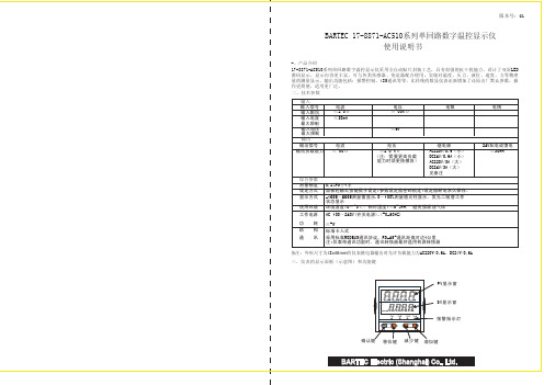
510系列说明书最终版

二、技术参数
输入
输入信号 输入阻抗 输入电流
电流 ≤250Ω ≤30mA
电压 ≥500KΩ
电阻
最大限制
输入电压 最大限制
≤6V
输出
输出信号
电流
电压
继电器
输出负载能力 ≤500Ω
≥250 KΩ (注:需要更高负载
能力时须更换模块)
AC220V/0.6(小) DC24V/0.6A(小) AC220V/3A(大)
★ 返回工作状态 1 手动返回:在仪表参数设定模式下,按压 键4秒后,仪表即自动回到实时测量状态。 2 自动返回:在仪表参数设定模式下,不按任何按键,30秒后,仪表将自动回到实时测量状态。 六、参数设置
6.1一级参数设置
在工作状态下,按压 键PV显示LOC,SV显示参数数值:按 或 键来进行设置,长按 键2秒可返回上 一级参数,Loc等于任意参数可进入一级参数
五、通电设置 仪表接通电源后,即进入自检状态(见右图),自检完毕后,仪表自动转入工作状态, 在工作状态下,按压 键显示LOC,LOC参数设置有如下: 1、1) Loc等于任意参数可进入一级菜单(LOC=00;132时无禁锁);
2) Loc=132,按压 键4秒可进入二级菜单; 3) Loc=130,按压 键4秒可进入时间设置菜单;对于带打印功能的表. 4) Loc等于其他值,按压 键4秒退出到测量画面。 2、如果Loc=577,在Loc菜单下,同时按住 键和 键达4秒,可以将仪表的 所有参数恢复到出厂默认设置。 3、在其它任何菜单下,按压 键4秒即可退出到测量画面。 4、在测量画面下同时按压 键和 键4秒,可修改一级参数的报警值。 5、采用热电偶信号输入时,通道小数点dP=0时,温度显示分辨率为1℃;dP=1 时,温度显示分辨率为0.1℃,(1000℃以上自动转为1℃分辨率)。 6、时间设定 在仪表PV显示测量值的状态下,按压 键进入参数,设定LOC=130,在PV显示LOC,SV显示130的状态下,按压 键4秒,即进入时间参数设定,仪表PV显示"dATE",SV显示当前日期(如:100120-2010年1月20日),在此状态下 ,可参照仪表参数设定方法,设定当前日期。在仪表当前日期显示状态下,按压 键,仪表PV显示"TlnE",仪表 SV将显示当前时间(如183047 -18点30分47秒),在此状态下,可参照仪表参数设定方法,设定当前时间。在仪 表当前时间显示状态下,再次按压 键,则退出时间设定,回至PV测量值显示状态。
FIBOCOM软件升级说明

软件升级说明文档版本: VR1.0.8 更新日期: 2013-10-25版权声明版权所有©深圳市广和通实业发展有限公司2013。
保留一切权利。
非经本公司书面许可,任何单位和个人不得擅自摘抄、复制本文档内容的部分或全部,并不得以任何形式传播。
注意由于产品版本升级或其他原因,本文档内容会不定期进行更新。
除非另有约定,本文档仅作为使用指导,本文档中的所有陈述、信息和建议不构成任何明示或暗示的担保。
商标申明为深圳市广和通实业发展有限公司的注册商标,由所有人拥有。
目录1前言 (5)2详细流程说明 (6)2.1升级所需软硬件工具说明 (6)2.1.1软件工具说明 (6)2.1.2硬件工具说明 (6)2.2升级方法及说明 (6)2.2.1搭建环境 (6)2.2.2升级模块程序步骤 (8)2.2.3升级用户程序步骤 (10)1 前言本文档主要说明FIBCOM品牌的G5/G6系列模块的软件升级的方法和说明,主要针对FAE和客户使用。
2 详细流程说明2.1 升级所需软硬件工具说明2.1.1 软件工具说明2.1.2 硬件工具说明2.2 升级方法及说明2.2.1 搭建环境情形1:模块不在转接板上,使用GT8619开发板如果模块不在转接板上:将模块的Uart1_TXD和Uart1_RXD连接到USB转串口(TTL电平)的TXD 和RXD相连。
图2-1情形2:模块不在转接板上,使用GT8629开发板如果模块不在转接板上:将模块的Uart1_TXD和Uart1_RXD连接到USB转串口(TTL电平)的TXD 和RXD相连。
图2-2情形3:模块在转接板上,使用GT8619开发板如果模块在转接板GT8660上:将模块+GT8660安装在GT8619上,使用USB线,连接GT8619到PC。
连接方法见下图:图 2-3情形4:模块在转接板上,使用GT8629开发板如果模块在转接板GT8660上:将模块+GT8660安装在GT8629上,使用USB线连接GT8629到PC。
FIBOCOM_G510 硬件用户手册_V1.1.4

3.4 开关机................................................................................................................................................. 13
2
简介.................................................................................................................................................. 7
注意
由于产品版本升级或其他原因,本文档内容会不定期进行更新。除非另有约定,本文档仅作为使用指导, 本文档中的所有陈述、信息和建议不构成任何明示或暗示的担保。
商标申明
为深圳市广和通无线股份有限公司的注册商标,由所有人拥有。
版本记录
文档版本 V1.0.0 V1.0.1 V1.0.2 V1.0.3 V1.0.4 V1.0.5 V1.0.6 V1.0.7 V1.0.8 V1.0.9 V1.1.0 V1.1.1 V1.1.2 V1.1.3 V1.1.4 更新日期 2013-02-04 2013-04-03 2013-04-26 2013-05-09 2013-06-03 2013-06-17 2013-07-31 2013-08-12 2013-11-26 2014-08-19 2014-12-26 2015-04-21 2015-08-24 2015-12-30 2016-07-14 说明 初始版本 更新 LPG,UART 更新性能描述 更新 3.7 串口,添加 UART2 和 HOST UART 描述 删除支持 2 路 ADC 描述,更新管脚定义说明 更新图 3-8,图 3-9 和图 5-2 更新文档名称 增加 3.6.3 章节 增加 G510-A20-00 更新 SIM_DATA 的描述 公司名称变更,更新为“深圳市广和通无线股份有限公司” PCB Layout 部分增加顶部视图说明 更新 logo 增加 PCB SMT 提醒 删除适用型号 G510-A20-00
狄耐克产品使用手册

目录一系统概述 (01)二系统操作 (04)三系统编程 (11)四系统配置及选材 (22)五系统原理图 (25)六系统连线示意图 (31)七安装调试 (35)八系统各部件的安装说明 (37)九其它事项 (37)版本:V3.0备注:本手册中所提及的终端设备(门口机、分机、管理机、围墙机),除特别说明外,主要是以可视系统AB-6A-402的设备为主。
一、系统概述AB-6A-402楼宇对讲系统是采用单片机微电脑控制技术,数位总线传输技术而设计的小区联网可视对讲系统。
系统数据传输距离可达5000米(需加中继器),防雷抗干扰,可实现大型小区的系统联网。
AB-6A-401楼宇对讲系统是非可视系统,除无视频外,其余性能与AB-6A-402系统相同。
两种系统主要适用于高楼大厦房型。
整个系统由门口主机(带联网功能)、室内分机、楼层交换机、主机电源、管理中心、管理中心电源、多门选择器、围墙机、信号中继器以及联网交换机等设备构成。
(见下表)◇编码门口主机AB-402D长×宽×厚(mm)外形尺寸:316×136×56开孔尺寸:280×114×34◇可视室内分机长×宽×厚(mm)外形尺寸:220×205×65(AB-402M)235×188×50(AB-402MQ)◇楼层交换机(AB-402A,AB-402B)长×宽×厚(mm)外形尺寸:126*150*40◇主机电源/交换机电源/管理中心电源(UPS-DP/UPS-P/UPS-CP)长×宽×厚(mm)外形尺寸:190×180×73◇管理中心(AB-602C)长×宽×厚(mm)外形尺寸:430×260×55 mm二、系统操作(一)门口机(402D)与用户分机通话1.来访者键入用户分机号码,若号码正确,则门口机发出悦耳的回铃声,呼叫开始。
厦门才茂 CM510-62G 62C 无线传输终端 使用手册说明书

厦门才茂CM510-62G/62C无线传输终端使用手册厦门才茂通信科技有限公司厦门市软件园二期望海路23号之一3层电话:传真:邮政编码:361009网址: 版权所有2003-2018----才茂通信通畅天下----说明书声明版权声明:本使用说明书包含的所有内容均受版权法的保护,未经厦门才茂通信科技有限公司的书面授权,任何组织和个人不得以任何形式或手段对整个说明书和部分内容进行复制和转载,并不得以任何形式传播。
商标声明:、才茂、Caimore和其他才茂商标均为厦门才茂通信科技有限公司的商标。
本文档提及的其他所有商标或注册商标,由各自的所有人拥有。
注意:由于产品版本升级或其他原因,本文档内容会不定期进行更新。
除非另有约定,本文档仅作为使用指导,本文档中的所有陈述、信息和建议不构成任何明示或暗示的担保。
特别声明:产品说明书上的建议配置或者默认配置,不代表合适配置,客户须根据自己业务需要情况,调整成为适应自己业务开展的配置。
产品出厂的配置参数,仅供用户参考,用户收到设备时,不管有没有其他约定,用户必须全部检查一遍,并须根据自己项目和业务需求,自行调整配置好相关参数。
由于参数配置不当或者错误导致的问题,我司不承担任何责任。
同时,用户需要加强病毒攻击防范工作,因为病毒攻击导致的通信异常,我司不承担任何责任。
技术支持:地址:厦门市软件园二期望海路23号之一302网址:客服电话:************************客服传真:************客服邮箱:*******************版本说明文档版本修改说明发布日期作者签发V1.0第一次正式发布2016.1.15Luot LiugbV1.2增加CDMA、短信配置2016.6.25Luot LiugbV1.3增加下装程序和配置方式2019.4.29Liugb LiugbV1.4增加注册包心跳包说明2019.06.05LiugbLiugb目录目录 (4)第一章产品简介 (5)1.1产品概述 (5)1.2系统组成 (6)1.3产品特点 (6)1.4产品功能 (6)1.5工作原理 (7)1.6技术参数 (7)第二章安装 (8)2.1概述 (8)2.2接线 (8)2.3接口说明 (10)第三章下装程序 (12)3.1下装程序 (12)第四章配置方式 (15)4.1本地串口配置参数 (15)4.2远程配置参数 (16)4.3短信配置IP端口(对端手机号发短信给DTU) (19)4.4注册包配置 (19)4.5心跳包配置 (20)第五章性能测试 (21)5.1供电电源 (21)5.2检测网络情况 (21)附件一:AT指令 (21)附件二:设备功耗 (22)附件三:接口类型 (22)附件四:常见故障分析 (22)附件五:TCP才茂协议文档 (23)附件六:网络参数表格 (23)第一章产品简介1.1产品概述CAIMORE低功耗CM510-62G/62C DTU(Data Transfer Unit,全称数据传输单元,本文简称DTU,下文62G/62C 简称62X)是一款为用户提供低功耗、高速、永远在线、TCP透明数据传输的工业级无线终端设备,最低功耗达到10mA@+9VDC。
《无线传感网络技术与应用》教学大纲

《无线传感网络技术与应用》教学大纲1.课程基本信息课程归口:嵌入式技术与应用等课程代码:学时数:90 学分:5先修课程:C语言程序设计、单片机应用技术、电子电路分析与实践等后续课程:物联网应用开发、毕业设计等2.课程地位与任务(1)课程在课程体系中的地位根据嵌入式技术与应用专业的电子信息技术领域职业岗位(群)的任职要求设置了该门课程,该课程是专业必修课程。
(2)课程的基本任务本课程采用“教、学、做”一体化教学模式,项目为导向、任务驱动等教学方法,旨在培养学生的ZigBee技术应用、蓝牙4.0应用、GPRS应用、WIFI应用、电路分析、测试、制作、调试能力及创新意识,为学生职业能力培养和职业素养养成起主要支撑或明显促进作用,为《物联网应用开发》、《毕业设计》等后续课程和今后的工作奠定了基础。
3.课程目标(1)能力目标A1.能正确安装与使用IAR、SmartRF Flash Programmer、Z-Stack等软件;A2.能熟练使用CC2530的基本组件;A3.能实现开关量、模拟量、逻辑量三种传感器的信号采集功能;A4.能实现基于Basic RF的无线采集与网络组建功能;A5.能熟练实现ZigBee无线网络的点对点通信、串口通信、串口透传、绑定等;A6.能获取网络拓扑结构、ZigBee无线网络的传感器数据采集与远程监控;A7.能熟练开发基于BLE协议栈的主从机连接、串口透传、手机与蓝牙通信等项目;A8.能熟练使用AT指令来控制GPRS无线通信模块;A9.能实现WIFI无线通信功能。
(2)知识目标K1. 了解Wi-Fi、蓝牙、ZigBee等典型短距离无线通信网络技术及其应用领域;K2.了解IAR、SmartRF Flash Programmer等软件的菜单功能;K3.掌握CC2530单片机的GPIO、中断、定时器、串口、ADC等基本组件的原理;K4.掌握Basic RF Layer工作机制、开关量、模拟量、逻辑量三种传感器的工作原理;K5.掌握Z-Stack协议栈结构、BLE协议栈的基本概念;K6.掌握Z-Stack协议栈的网络管理;K7.掌握基于BLE协议栈的串口通信、主从机连接与数据传输等所需的知识;K8.掌握拨打与接听电话、短信的读取与发送、GPRS通信等AT指令;K9.了解WIFI无线通信应用的相关知识。
广和通NL668

SIM应用设计说明文档版本:V1.0.6更新日期:2017-05-23版权所有©2017深圳市广和通无线股份有限公司。
保留一切权利。
非经本公司书面许可,任何单位和个人不得擅自摘抄、复制本文档内容的部分或全部,并不得以任何形式传播。
注意由于产品版本升级或其他原因,本文档内容会不定期进行更新。
除非另有约定,本文档仅作为使用指导,本文档中的所有陈述、信息和建议不构成任何明示或暗示的担保。
版本记录文档版本更新日期说明V1.0.02013-08-01初始版本V1.0.12014-02-10根据目前SIM卡性能变化,对SIM卡信号上的电容,ESD器件带来的影响需要根据实际情况确认,然后进行优化改善。
V1.0.22014-07-28修改G510R1设置说明。
V1.0.32014-08-19更新G510R1设置说明。
V1.0.42014-12-26公司名称变更,更新为“深圳市广和通无线股份有限公司”V1.0.52015-08-24更新公司logoV1.0.62017-05-23添加模块产品型号序号型号说明1适用于所有包含SIM接口的通信模块目录1SIM接口简介 (5)2SIM卡设计 (6)2.1SIM连接器选型推荐 (6)2.2SIM原理图设计 (7)2.3SIM设计要点 (8)3SIM信号的射频干扰处理 (9)3.1射频干扰产生原理 (9)3.2针对性改善措施 (10)4SIM热插拔设计 (10)4.1硬件连接 (10)4.2软件设置 (10)4.3系统与模块通讯端口的调试 (11)1SIM接口简介Fibocom模块集成了SIM卡接口,其特点如下:•支持1.8V和3.0V(电压自适应)•支持SIM卡状态检测(部分型号)SIM接口管脚说明:管脚名称管脚说明备注SIM_CLK串行时钟,3.25MHzSIM_VCC SIM卡供电,电压自适应部分型号命名为VSIMSIM_DATA串行输入输出信号部分型号命名为SIM_IO;模块内部已上拉到SIM_VCCSIM_RST SIM卡复位管脚,低电平有效SIM_CD SIM卡状态检测部分型号支持SIM_GND SIM卡的电源地部分型号支持没有则直接接地Fibocom模块支持并自动识别1.8V和3.0V的SIM卡。
【VIP专享】PLAC-5105L使用说明书V1.3(20111114)

4.1 模拟量输出的设置技巧........................................... 11 3.2 日期时间的设置技巧............................................. 11 3.3 打印机的设置技巧............................................... 12 3.4 峰值检测的设置技巧............................................. 12
SeTAQ
PLAC-5105L 使用说明书
第一章 概述
PLAC-5105 系列称重显示控制器是山东西泰克仪器有限公司自主研发的 工业级通用称重显示控制器,能够在显示重量值的情况下,并行的将普通传 感器信号变送为 4-20mA、0-5V 或 0-10V 模拟信号,同时保持与计算机、PLC 等上位机的通信(或者是接串口打印机进行重量日期的打印,仅 PLAC-5105L 具有此功能);具有抗干扰能力强、功能强大、操作简便、通用性强、温漂小、 线性度高等特点。
PLAC-5105L 是 PLAC-5105 系列中功能最为强大的。除了具有上述功能之 外,PLAC-5105L 还具有以下强大的功能:带日历并且掉电不丢失、可接串口 打印机来打印日期时间重量和地址等信息,方便称重数据的存档。
PLAC-5105L 分为 PLAC-5105L、PLAC-5105L-I、PLAC-5105L-UI 三个 型号;其中,PLAC-5105L 型不具有 DA 输出功能,PLAC-5105L-I 型仅能输出 4-20mA 电流信号,PLAC-5105L-UI 型具有 0~5V,0~10V 电压输出、4~20mA 电流输出功能;其中以 PLAC-5105L-UI 型的功能最为强大。
如何让单片机联网:WiFiPro-C5110技术资料

WiFiPro-C5110简介技术特点:1、带WiFi的51单片机模块(WiFi+51单片机一体化),兼容DIP40脚5V C51单片机,可直接替换DIP40脚单片机,原来的开发板和产品立刻升级为具备WiFi网络通讯的产品。
2、内置双串口单片机STC12C5A60S2,所有单片机指令全部参考STC12C5A60S2;3、WiFiPro 移植了HTML5 Web服务器,自动识别Socket(TCP/IP、UDP、HTTP协议)、FlashSocket、WebSocket ,上位机无论是用VB、VC++、C#、JAVA,还是Adobe Falsh(AIR)、HTML5(JS+CSS3)开发语言工具,都能很好的适应,在Adobe Flash 、HTML5 Web跨平台控制开发方面尤为突出,全面兼容Windows、Android、iOS。
4、WiFiPro封装了全部的WiFi及TCP/IP网络细节,通过Web页面设置好参数,单片机无需复杂的WiFi和网络操作,只需要把数据发送到串口,所有的传输由WiFiPro完成,网络接收的数据直接通过串口进入单片机,二次开发非常简单。
技术参数:1.电源:DC5V,最大电流150mA;2.通讯方式:WiFi无线网络;3.通讯协议:TCP/IP、UDP、FlashSocket、WebSokcet、HTTP;4.WiFi模式:STA模式和AP模式共存,手机可通过AP模式直接连接WiFi模块,也可以通过Web设置,使模块加入路由器形成网络节点组网。
5.软件支持:上位机开发可选择VB、C++、C#、JAVA、Adobe Flash HTML5(JS+CSS3);6.跨平台:利用HTML5 Web 开发跨平台控制界面,Windows、Linux、Android、iOS(苹果)上运行,可直接控制开发板上的资源(IO端口、UART串口通讯),用户可将HTML5控制界面植入模块中,实现免APP安装运行方式,或者使用二维码扫描运行。
深圳台达实业g510变频器说明书

深圳台达实业g510变频器说明书
深圳台达实业G510变频器是一款性能卓越的中型应用电机变频器,采用高速
微处理技术,适用于中小型异步电动机及各种负载,并且可以实现恒功率运行,以及运行控制、节能、自动控制等一系列功能。
深圳台达实业G510变频器采用高速确定1024级分辨率全数字调节,技术无比
先进。
它采用PC卡及模芯缓存,可让操作者在不同场所拔插变频器,操作简便。
它采用过程控制低噪音,可完美配合节能设备,对环境无污染。
除此之外,它的智能故障显示技术也是它的一大特色,可以帮助操作者有意识快速准确的定位问题所在,大大提升操作效率。
深圳台达实业G510变频器还具有很多其他高级功能,比如变频范围设置,可
以通过变频器来控制机电系统的运行范围;支持多种行程开关量输入,可以实现变频调速功能;支持脉宽调制输入,可以实现恒定速运行等功能。
总的来说,深圳台达实业G510变频器有着卓越的性能,采用的技术极其先进,拥有了自动控制、节能、低噪音等多种功能,适用于各种中小型电动机与负载,是一款非常出色的变频器。
UHC Bb-远传装置 使用说明书

UHC |Bb-远传装置MAGNETIC LEVEL GAUGE UHC型磁性浮子液位计Bb-远传装置使用说明书UHC-Bb-DT-JS-1027-2018(A)前言感谢您选择丹东通博电器(集团)有限公司的产品。
本使用说明书给您提供有关安装、连接和调试以及针对维护、故障排除和贮存方面的重要信息。
请在安装调试前仔细阅读并将它作为产品的组成部分保存在仪表的近旁,供随时翻阅。
并可通过输入版本号下载本说明书。
如未遵照本说明书进行操作,则本仪表所提供的防护可能会被破坏。
商标、版权和限制说明通博、通博电器、通博泵业、DDTOP、均为公司的注册商标。
本仪表的性能规格自发布之日起生效,如有更改,恕不另行通知。
丹东通博电器(集团)有限公司有权在任何时候对本说明书所述的产品进行修改,恕不另行通知。
质保丹东通博电器(集团)有限公司保证所有刮板流量计自出厂之日起,一年之内无材料和制造工艺方面的缺陷。
在质保期内,如产品出现质量问题而返回,提出的索赔要求经制造厂检验后确定属于质保范围内,则丹东通博电器(集团)有限公司负责免费为买方(或业主)维修或更换。
丹东通博电器(集团)有限公司对因设备使用不当,劳动力索赔、直接或后续损伤以及安装和使用设备所引起的费用概不负责。
除了关于丹东通博电器(集团)有限公司某些产品的特殊书面保修证明,丹东通博电器(集团)有限公司不提供任何明示或暗示的质量保证。
质量丹东通博电器(集团)有限公司通过了ISO9001质量体系认证,产品生产的全过程均严格依照质量体系的规定范围执行,对产品和服务质量提供最强有力的保证。
目录1安全提示 (3)1.1爆炸可能会导致死亡或严重伤害。
(4)1.2过程泄漏可能导致严重伤害或死亡。
(4)1.3不遵守安全安装准则可能导致死亡或严重受伤。
(4)2产品说明 (4)2.1 产品主要结构 (4)2.2 工作原理 (4)2.3包装 (5)2.4吊装运输时 (5)2.5仓储 (5)3技术特性 (5)3.1主要性能 (5)3.2主要参数 (5)4外形尺寸示意图 (6)5开箱及检查 (7)5.1开箱验货注意事项 (7)5.2检查内容 (7)6安装 (7)6.1安装工具 (7)6.2安装操作过程-图5 (7)7调试 (8)7.1 远传装置调试 (8)8注意事项 (12)9故障分析与排除 (12)10拆卸 (12)10.1警告 (12)10.2 废物清除 (12)11 产品认证 (12)1安全提示出于安全的原因,明确禁止擅自改装或改变产品,维修或替换只允许使用由制造商指定的配件。
ioSafe x513 硬件使用手册说明书

910-11637-00 Rev03 HARDWARE GUIDE, X513, ENGTable of ContentsChapter 1: Before You StartPackage Contents (3)ioSafe at a Glance (4)Safety Instructions (5)Chapter 2: Hardware SetupTools and Parts for Hard Disk Installation (6)Install Hard Disks (6)Connecting to the ioSafe NAS (10)Replace System Fan Assembly (11)How to configure in Disk Station Manager (12)Chapter 3: Product SupportData Recovery Proceedure (14)Contact Us (14)Appendix A: SpecificationsAppendix B: LED Indication TableBefore You StartBefore you start setting up the ioSafe, please check the package contents to verify that you have received the items below. Please also read the safety instructions carefully before use to prevent your ioSafe from any damages.Note:ioSafe uses an unmodified version of Synology’s DSM. The software interface will sometimes refer to the Synology Product the ioSafe is based on.Package ContentsMain unit x 1AC power cord x 1Expansion cable x 1Screws for 3.5” hard drives x 24(Diskless Only)3mm Hex Tool x1Magnet x1Note: For storing the hex toolon the back of the deviceioSafe at a GlanceNo.Article NameLocationDescription1) Power Button Front PanelIn default mode: x513 will be turned on or off automatically when the connected Synology DiskStation powers on or off. In manual mode:1. When x513 is connected to cross-volume models, the power button has no power-on/off functions.2. When x513 is connected to independent-volume models, press the power button to power it on. To power off x513, press and hold the button until the Power LED starts blinking.Note: For cross-volume and independent volume models, please refer to the Hardware Specifications table on Page 2.2) LED IndicatorsFront PanelDisplays the status of internal disks and the system. For more information, see LED Indication Table in Appendix B. 3) HDD Indicators 4) Expansion Port Back Panel Connect to a compatible ioSafe NAS5) RESET Button Back Panel Reboot x513 and restore its settings to factory default.6) Default/ManualSwitch Back Panel Switch between power modes to turn x513 on/off automatically or manually. 7) Power Port Back Panel The power port is where you connect the power cord to the ioSafe.8)FansBack PanelThe fans are built to exhaust waste heat. It will start automatically when the server starts. If the fan is malfunctioning, the system will beep every few seconds.Safety InstructionsBefore cleaning, unplug the power cord first. Wipe ioSafe product with damppaper towels.Do not place the ioSafe product on a cart, table, or desk, which is not stable to avoid the product from falling over.The power cord must plug in to the right supply voltage. Make sure that the supplied AC voltage is correct and stable.To remove all electrical current from the device, ensure that all power cords are disconnected from the power source.Risk of explosion if battery is replaced with an incorrect type. Dispose of used batteries appropriately.3-2-1At ioSafe, we suggest a minimum of the "3-2-1 Rule" for backup: Make 3 complete copies of your data, keep them on at least 2 separate systems, and have at least 1 protected from natural disaster.Hardware SetupTools and Parts for Hard Disk Installation▪A Phillips screwdriver▪3mm Hex Tool (included)▪At least one 3.5" or 2.5" SATA hard disk(Please visit for compatible hard disk models.)Warning: If you install a hard disk that contains data, the system will format the hard disk and erase all data. If you need the data in the future, please back it up before installation.Install Hard Disks1 Remove the Front Cover using the include 3mm Hex Tool2 Remove the Waterproof Drive Cover using the 3mm Hex Tool.3 Remove the Drive trays using the provided 3mm Hex Tool.4 Install a compatible Hard Drive into each Drive Tray using (4x) Drive Screws and a Phillips screwdriver.(Please visit for compatible hard drives models.)Note: If you want to set up a RAID set, it is recommended that all installed hard disks are of the same size to make the best use of hard disk capacity.5 Insert the loaded hard drive tray into the empty hard drive bay and tighten the screws using the 3mm Hex Tool.Important: Make sure the tray is pushed in all the way. Otherwise, the hard disk might not be able to function properly.6 Replace the Waterproof Drive Cover and securely tighten using the supplied 3mm Hex ToolWARNING: BE SURE TO TIGHTEN THIS SCREW USING THE PROVIDED HEX TOOL. THE HEX TOOL IS DESIGNED TO FLEX SLIGHTLY WHEN THE SCREW IS SUFFICIENTLY TIGHT AND THE WATERPROOF GASKET IS PROPERLY COMPRESSED. AVOID USING TOOLS OTHER THAN THE SUPPLIED HEX TOOL AS YOU COULD UNDER TIGHTEN OR BREAK THE SCREW.7 Install the Front Cover to finish the installation and protect the drives from fire. Keep the Hex Tool nearby for future use. A magnet is provided to attach the Hex Tool to the back of the ioSafe or some other convenient location.Connecting to the ioSafe NAS1 Connect one end of the power cord to the power port of x513, and the other to the power outlet.2 Connect the expansion cable between the expansion ports of x513 and a compatible ioSafe NAS.Note:After the connection is complete, x513 will be turned on or off automatically when the connected ioSafe NAS powers on or off.Replace System Fan AssemblyFollow the steps below to replace the malfunctioning fans with a good set.To replace the system fans:1 Shut down your ioSafe x513. Disconnect all cables connected to your ioSafe to prevent any possible damages.2 Remove the 7 perimeter screws that secure the malfunctioning fan assembly.3 Remove the malfunctioning fan assembly:a Pull the assembly from the back panel of your ioSafe to expose the fan connections.b Disconnect the fan cables from the connector located near the bottom of the fan socket, and then remove theassembly.4 Install the new fan assembly:a Connect the fan cables of the new fans to the fan connectors.5 Replace and tighten the 7 screws you removed in step 2.How to Configure in DiskStation ManagerImportant: Before starting to use ioSafe NAS with the x513 Connected, please see the following limitations of x513.•x513 Expansion unit can be paired with only one compatible ioSafe NAS.•The data of applications (such as Photo Station and Audio Station) can be stored on x513 only if you expand the internal volume of the master NAS with x513. They will not be stored on x513 if you create a new independent volume.•Hard drives previously used in an ioSafe NAS will not be readable by directly inserting them into x513, and vise versa.To configure your new x513, please follow the steps below:1 Power on your ioSafe NAS master unit.2 Open your DiskStation Manager with a web browser. Go to Main Menu > Control Panel > Devices and Printers to confirm x513 is connected to your ioSafe.3 Go to Main Menu > Storage Manager to manage x513 for storage creation or expansion.•If you want to create a new volume with x513, click Create and follow the Volume Creation Wizard to complete the creation (This is the preferred method).•If you want to expand the existing volume with x513, select the volume you want to expand from the volume list, click Manage, and follow the Volume Manager Wizard to complete the expansion.For detailed information about volume management, please go to Main Menu > Storage Manager and see the help page by clicking the help button at the top-right corner.Congratulations! Your x513 is now set up and ready to use. For more information or online resources about x513, please visit o r .Product SupportCongratulations! You are now ready to manage and enjoy all the features of your ioSafe. For more information regarding specific features, please check out DSM Help or refer to our online resources available at or .Data Recovery ProcedureIf the ioSafe faces possible data loss for any reason, you should immediately call the ioSafe Disaster Response Team at 1-888-984-6723 (US & Canada) or 1-530-820-3090 (International) extension 430. You can also send an email to **************************. The professionals at ioSafe can determine the best actions to take to protect your valuable information. In some cases a self-recovery can be performed and provide you with immediate access to your information. In other cases, ioSafe may request that the product be returned to the ioSafe factory for data recovery. In any case, contacting ioSafe is the first step.The general steps for disaster recovery are:1. ***************************************************,producttypeanddateofpurchase.2. If you cannot email, call ioSafe Disaster Support Team at 1-888-984-6723 (US & Canada) or 1-530-820-3090(International) extension 4303. Report disaster event, and obtain return shipping address/instructions4. Follow ioSafe team instructions on proper packaging.5. ioSafe will recover all data which is recoverable according to the terms of the Data Recovery Service Termsand Conditions.6. ioSafe will then place any recovered data on a replacement ioSafe device7. ioSafe will ship the replacement ioSafe device back to the original user8. Once the primary server / computer is repaired or replaced, the original user should restore the primary drivedata with the ioSafe backup dataContact UsCustomer SupportUSA Toll Free Phone: 888.98.IOSAFE (984.6723) x400International Phone: 530.820.3090 x400Email: **************************Technical SupportUSA Toll Free Phone: 888.98.IOSAFE (984.6723) x450International Phone: 530.820.3090 x450Email: **********************Disaster SupportUS Toll Free Phone: 888.98.IOSAFE (984.6723) x430International Phone: 530. 820.3090 x430Email: **************************Corporate HeadquartersioSafe, Inc.10600 Industrial Ave, Suite 120Roseville, CA 95678Ap p e n di x SpecificationsItem ioSafe x513Fire Protection Protects data from fire. Up to 1550°F (843°C), 30 minutes per ASTME-119.Flood Protection Protects data from flood. Fully submersed, fresh or salt water, 10 foot(3m) depth, 72 hours.Compatible Drive Type 3.5" SATA(III) / SATA(II) HDD 2.5" SATA(III) / SATA(II) HDD 2.5" SATA(III) / SATA(II) SSDMax. Capacity 40TB (5x 8TB hard drives)Hot Swappable HDD YesSize (HxWxD) (mm) 375 x 222 x 318Weight (Kg) 27AC Input PowerVoltage100V to 240V ACPower Frequency 50/60Hz Single PhaseOperating Temperature 40 to 95˚F (5 to 35˚C)Relative Humidity 5% to 95% RHMaximum OperatingAltitude6,000 feet (2,000 m)Agency Certifications FCC Class B, CE Class B, BSMI Class BAp p e n di x LED Indication TableLED Indication Color Status DescriptionALERTOrange Static System fan is not workingOff System fan normaleSATAGreen Static Connected to a NASOff Disconnected from a NASHard Disk StatusGreenStatic Disk ready and idleBlinking Disk is being accessed Orange Static Cannot Read/Write, Errors occur Off No internal diskPOWERBlue Static Power onOff Power offSTATUSGreen Static RAID created Orange Blinking RAID degradedOff No RAID or RAID crashed。
网件WAC510无线接入点安装指南说明书

Set Up the Access PointThe following table shows the different setup options that are available toyou and the requirements for the access point (AP).Note: For more information about the various setup options, see the NETGEAR Insight Managed Smart Cloud Wireless Access Point (WAC510) User Manual which you can download by visiting /support .Before mounting the access point in a high location, first set up, configure, and test the access point to verify WiFi network connectivity. Make sure that you are running the latest firmware version on your device. ¾To set up the access point with a PoE switch:Connect an Ethernet cable from the yellow WAN PoE port on the access point to a Power over Ethernet (PoE) switch.In this setup, the access point does not require a power adapter.Package ContentsUnpack the box and verify the contents:• NETGEAR Insight® Managed Smart Cloud Wireless Access Point(WAC510)• Installation guide• Ceiling and wall installation kitFebruary 2018© NETGEAR, Inc., NETGEAR and the NETGEAR Logo are trademarks of NETGEAR, Inc. Any non‑NETGEAR trademarks are used for reference purposes only.NETGEAR, Inc.350 East Plumeria DriveSan Jose, CA 95134, USANETGEAR INTL LTDBuilding 3, University Technology Centre Curraheen Road, Cork, IrelandConfigure the Access Point¾Choose one of the following methods to configure the access point:• Method 1: Use the NETGEAR Insight app . On your iOS orAndroid mobile device, go to the app store. Search for NETGEAR Insight, and download the app.Open the NETGEAR Insight app and log in to your existing NETGEAR account or create a new account to log in with. Then, follow the prompts in the NETGEAR Insight app to discover and register the access point on the network so that you can configure and manage the access point. For more information on the NETGEAR Insight app, see the NETGEAR knowledge base articles at /support .• Method 2: Log in over WiFi . From your computer or mobiledevice, connect over WiFi to the access point’s default SSID. Thedefault SSID is on the access point label on the bottom of the access point and is shown in the format NETGEAR xxxxxx -SETUP. The default password is sharedsecret .Open a web browser. In the address bar, enter (or ). The Day Zero Easy Setup page displays so that you can configure the basic settings, including the country of operation. After you save these basic settings, the Day Zero Easy Setup page no longer displays when you log in.• Method 3: Log in over Ethernet . Open a web browser from acomputer that is connected to the same Ethernet subnet as the access point or to the access point’s LAN port directly through anSupportThank you for purchasing this NETGEAR product. You can visit/support to register your product, get help, access the latest downloads and user manuals, and join our community. We recommend that you use only official NETGEAR support resources.Si ce produit est vendu au Canada, vous pouvez accéder à ce document en français canadien à /other/.(If this product is sold in Canada, you can access this document in Canadian-French at /other/.)For more information about the installation and configuration options, visit /support to access the user manual.For the current EU Declaration of Conformity, visit/app/answers/detail/a_id/11621/.For regulatory compliance information, visit /about/regulatory/.See the regulatory compliance document before providing power to the access point.Ethernet cable.In the address bar, enter the IP address of the access point.Note: If the access point is connected to a network that includes a DHCP server (or router that functions as a DHCP server), determine the IP address by using an IP network scanner. Otherwise, the default IP address of the access point is 192.168.0.100. If you use an Ethernet cable from your computer to the access point’s LAN port and the access point functions with its default IP address, make sure that the IP address of your computer is in the 192.168.0.x subnet.The Day Zero Easy Setup page displays so that you can configure the basic settings, including the country of operation. After you save these basic settings, the Day Zero Easy Setup page no longer displays when you log in.Note: Make sure the country is set to the location where the device is operating. The customer is responsible for complying within the local, regional, and national regula-tions set for channels, power levels, and frequency ranges.Deploy the Access PointThe best location for the access point is elevated, such as mounted on a wall or ceiling, at the center of the WiFi coverage area, and within line of sight of all mobile devices.For information about mounting the access point, see the NETGEAR Insight Managed Smart Cloud Wireless Access Point (WAC510) Ceiling and Wall Installation Guide , which you can download from /. ¾To deploy the access point:1. Disconnect the access point and position it where you will deploy it.2. Reconnect the access point. See Set Up the Access Point .3. Using a WiFi device, verify connectivity by connecting to the access pointand using a browser to connect to the Internet.Troubleshooting TipsThe following table provides some tips for correcting simple problems that you might encounter. For more troubleshooting information, see the NETGEAR Insight Managed Smart Cloud Wireless Access Point (WAC510) User Manual .Insight。
利用zigbee的无线单片机温度计课程设计2-推荐下载

CRC 校验码,具有极强的抗干扰纠错能力 用户可分别设定各路温度的上、下限 适应电压范围宽,3.0~5.5V,在寄生电源方式下可由数据线供电
2.2.2 DS18B20 的管脚分布
I
对全部高中资料试卷电气设备,在安装过程中以及安装结束后进行高中资料试卷调整试验;通电检查所有设备高中资料电试力卷保相护互装作置用调与试相技互术通关,1系电过,力管根保线据护敷生高设产中技工资术艺料0不高试仅中卷可资配以料置解试技决卷术吊要是顶求指层,机配对组置电在不气进规设行范备继高进电中行保资空护料载高试与中卷带资问负料题荷试2下卷2,高总而中体且资配可料置保试时障卷,各调需类控要管试在路验最习;大题对限到设度位备内。进来在行确管调保路整机敷使组设其高过在中程正资1常料中工试,况卷要下安加与全强过,看度并22工且22作尽22下可22都能22可地护以缩1关正小于常故管工障路作高高;中中对资资于料料继试试电卷卷保破连护坏接进范管行围口整,处核或理对者高定对中值某资,些料审异试核常卷与高弯校中扁对资度图料固纸试定,卷盒编工位写况置复进.杂行保设自护备动层与处防装理腐置,跨高尤接中其地资要线料避弯试免曲卷错半调误径试高标方中高案资等,料,编试要5写、卷求重电保技要气护术设设装交备备置底4高调、动。中试电作管资高气,线料中课并敷3试资件且、设卷料中拒管技试试调绝路术验卷试动敷中方技作设包案术,技含以来术线及避槽系免、统不管启必架动要等方高多案中项;资方对料式整试,套卷为启突解动然决过停高程机中中。语高因文中此电资,气料电课试力件卷高中电中管气资壁设料薄备试、进卷接行保口调护不试装严工置等作调问并试题且技,进术合行,理过要利关求用运电管行力线高保敷中护设资装技料置术试做。卷到线技准缆术确敷指灵设导活原。。则对对:于于在调差分试动线过保盒程护处中装,高置当中高不资中同料资电试料压卷试回技卷路术调交问试叉题技时,术,作是应为指采调发用试电金人机属员一隔,变板需压进要器行在组隔事在开前发处掌生理握内;图部同纸故一资障线料时槽、,内设需,备要强制进电造行回厂外路家部须出电同具源时高高切中中断资资习料料题试试电卷卷源试切,验除线报从缆告而敷与采设相用完关高毕技中,术资要资料进料试行,卷检并主查且要和了保检解护测现装处场置理设。备高中资料试卷布置情况与有关高中资料试卷电气系统接线等情况,然后根据规范与规程规定,制定设备调试高中资料试卷方案。
广和通NL668

SIM应用设计说明文档版本:V1.0.6更新日期:2017-05-23版权所有©2017深圳市广和通无线股份有限公司。
保留一切权利。
非经本公司书面许可,任何单位和个人不得擅自摘抄、复制本文档内容的部分或全部,并不得以任何形式传播。
注意由于产品版本升级或其他原因,本文档内容会不定期进行更新。
除非另有约定,本文档仅作为使用指导,本文档中的所有陈述、信息和建议不构成任何明示或暗示的担保。
版本记录文档版本更新日期说明V1.0.02013-08-01初始版本V1.0.12014-02-10根据目前SIM卡性能变化,对SIM卡信号上的电容,ESD器件带来的影响需要根据实际情况确认,然后进行优化改善。
V1.0.22014-07-28修改G510R1设置说明。
V1.0.32014-08-19更新G510R1设置说明。
V1.0.42014-12-26公司名称变更,更新为“深圳市广和通无线股份有限公司”V1.0.52015-08-24更新公司logoV1.0.62017-05-23添加模块产品型号序号型号说明1适用于所有包含SIM接口的通信模块目录1SIM接口简介 (5)2SIM卡设计 (6)2.1SIM连接器选型推荐 (6)2.2SIM原理图设计 (7)2.3SIM设计要点 (8)3SIM信号的射频干扰处理 (9)3.1射频干扰产生原理 (9)3.2针对性改善措施 (10)4SIM热插拔设计 (10)4.1硬件连接 (10)4.2软件设置 (10)4.3系统与模块通讯端口的调试 (11)1SIM接口简介Fibocom模块集成了SIM卡接口,其特点如下:•支持1.8V和3.0V(电压自适应)•支持SIM卡状态检测(部分型号)SIM接口管脚说明:管脚名称管脚说明备注SIM_CLK串行时钟,3.25MHzSIM_VCC SIM卡供电,电压自适应部分型号命名为VSIMSIM_DATA串行输入输出信号部分型号命名为SIM_IO;模块内部已上拉到SIM_VCCSIM_RST SIM卡复位管脚,低电平有效SIM_CD SIM卡状态检测部分型号支持SIM_GND SIM卡的电源地部分型号支持没有则直接接地Fibocom模块支持并自动识别1.8V和3.0V的SIM卡。
Kg510编程软件简易中文使用说明

Kg510写频软件使用说明(详细步骤)
一,打开KG510写频软件出现如下界面,选择VHF/UHF Base Station KG506/510,然后点击
Next 进入下一步。
图一
二,如下图所示,选择机型(例如:40A 或40D 等),然后选择“RS232C Port ”(选com1
或com2
等),然后点击“Main
”按钮进入下一步。
图二
三,如下图示点击“Chanel Menu ”按钮进入频率编辑界面
四,根据需要输入RX 和TX 频率,CTC 音频等信息如下图示;输入完毕后按“EXIT ”退
出到主界面(图三)
图四
五,在主界面(图三)上点击“Programming ”出现以下界面,点击“Program Write ”向KG510
写频,完毕后退出到主界面,按“END ”键退回到WINDOWS 桌面,写频完成。
图五
图三。
- 1、下载文档前请自行甄别文档内容的完整性,平台不提供额外的编辑、内容补充、找答案等附加服务。
- 2、"仅部分预览"的文档,不可在线预览部分如存在完整性等问题,可反馈申请退款(可完整预览的文档不适用该条件!)。
- 3、如文档侵犯您的权益,请联系客服反馈,我们会尽快为您处理(人工客服工作时间:9:00-18:30)。
版权声明
版权所有©2016 深圳市广和通无线股份有限公司。保留一切权利。 非经本公司书面许可,任何单位和个人不得擅自摘抄、复制本文档内容的部分或全部,并不得以任何形式 传播。
注意
由于产品版本升级或其他原因,本文档内容会不定期进行更新。除非另有约定,本文档仅作为使用指导, 本文档中的所有陈述、信息和建议不构成任何明示或暗示的担保。
1.6.1 潮湿预处理(预热处理)......................................................................................................... 8 1.6.2 推荐烘烤标准............................................................................................................................. 8 1.6.3 PCB 焊盘及对应钢网推荐设计.................................................................................................8 1.6.4 SMT 生产工艺参数及相关要求............................................................................................. 11
Note: if device containers cannot be subjected to high temperature or shorter bake times are desired. REFERENCE IPC/JEDEC J-STD-033 FORBAKE PROCEDURE. Bag seal date: Note:Level and body temperature defined by IPC/JEDEC J-STD-020
本文件版权属深圳市广和通无线股份有限公司所有,未经批准,不得复制。 G510 LCC SMT 应用设计说明 Page 6 of 14
CAUTION
This bag contains
LEVEL
3
MOISTURE-SENSITIVE DEVICES
1. 2. calculated shelf life in sealed bag:12 months at<40℃ and <90% relative humidity(RH) peak package body temperature:_____________________. If blank.see adjacent bar code label 3. After this bag is opened. Devices that will be subjected to reflow solder or other high temperature process must be a) b) mounted within 72 hours of factory conditions <30℃/60%RH,or stored at <10%RH
商标申明
为深圳市广和通无线股份有限公司的注册商标,由所有人拥有。
版本记录
文档版本 V1.0.0 V1.0.1 V1.0.2 V1.0.3 V1.0.4 V1.0.5 V2.0.0 更新日期 2013-04-26 2013-05-08 2013-06-17 2013-06-19 2014-04-08 2014-10-13 2016-01-20 说明 初始版本 更新文档名称 更新焊盘推荐设计及钢网推荐设计 增加适用型号 增加适用机型和更新推荐钢网厚度参数 细化钢网扩孔方向描述 增加包装方式说明,优化炉温曲线及说明
1.2 存储............................................................................................................................................... 6 1.3 湿度卡........................................................................................................................................... 7 1.4 干燥剂........................................................................................................................................... 8 1.5 车间寿命....................................................................................................................................... 8 1.6 使用............................................................................................................................................... 8
本文件版权属深圳市广和通无线股份有限公司所有,未经批准,不得复制。 G510 LCC SMT 应用设计说明 Page 3 of 14
目录
1 包装、存储和使用...................................................................................................................5
1.1.1 卷带包装
G510 每个卷盘内装有 250 个模块,卷带系统见下图 1-1:
图 1-1卷袋系统本文件版权属深圳市广和通无线股份有限公司所有,未经批准,不得复制。 G510 LCC SMT 应用设计说明 Page 5 of 14
包装过程,见下图:
图 1-2 卷袋包装过程
1.2 存储
存储条件(推荐) :温度 23±5℃,相对湿度 RH 35-70%。 存储期限(密封真空包装) :在推荐存储条件下,保存期为 12 个月。 其他存储要求:参照图 1-3。
2 其它注意事项....................................................................................................................... 14
2.1 重复焊接..................................................................................................................................... 14 2.2 波峰焊接..................................................................................................................................... 14 2.3 手工焊接..................................................................................................................................... 14 2.4 拆卸............................................................................................................................................. 14
1.6 使用
1.6.1 潮湿预处理(预热处理)
密封剂和基质材料易吸潮,在相对湿度 RH>10%或未满足车间寿命相关规定的情况下,为了防止在回 流焊接时出现 “爆米花”效应的裂痕和分层,需要在回流焊接和其它高温作业之前进行预热烘干处理。
1.6.2 推荐烘烤标准
持续烘烤时间:9 小时。 温度:125±5℃。 烤炉:对流换热炉。 注意: 如果在规定的时间内不能及时处理,将烘干的部件与干燥剂和湿度指示卡一起放入防潮袋中, 使用真空热障封口机将袋子密封,建议存储在氮气柜中。 请勿将卷盘包装方式的模块直接进行烘烤,烘烤之前需将模块置于防高温托盘内,然后进行 烘烤。
1.1 包装概述....................................................................................................................................... 5
1.1.1 卷带包装..................................................................................................................................... 5
4 devices require baking, before mounting, if: a) humidity indicator card is >10% when read at 23℃ ±5℃ ,or b) 3a or 3b not met. 5 if baking is required, devices may be baked for 9 hours at 125℃ ±5℃.
