TE1768-EK ISP使用手册
艾特顿9PX系列无线电源系统说明说明书

Eaton 9PX5KIBPEaton 9PX UPS, 5000 VA, 4500 W, Input: Hardwired, Outputs: (3) C13, (2) C19, Hardwired, Rack/tower, 3UGeneral specificationsEaton 9PX UPS 9PX5KIBP74317204053468.5 cm 44 cm 13 cm 48 kg 2 year CE Marked TUV cULus Listed CSA 22.2UL 1778 IEC/EN 62040-1 IEC/EN 62040-2 CE EACEaton 9PX 5000i HotSwapProduct Name Catalog Number UPCProduct Length/Depth Product Height Product Width Product Weight Warranty Compliances Certifications Model CodeView runtime graph Hot-swappable internal batteries and extended battery modules (EBMs)1512 V / 5 Ah Sealed, lead-acidYes(3) C13, (2) C19, Hardwired Online/Double-conversion 4500 W 5000 VA Sine wave 230V0.9230V default (200/208/220/230/240V)200/208/220/230/240 V +/- 1%250/60 Hz 1Hardwired/fixed connection 230V default (200/208/220/230/240V)176-276 V (100-276 V with derating)50/60 HzRuntime graph Battery management Battery replacementBattery quantity Battery rating Battery type Extended battery capability ReceptacleTopologyWattage VA rating Output waveform Voltage Output power factor Output nominal voltageOutput voltage rangeVoltage distortion output (linear load) - max Output frequency Feed type Input connectionInput nominal voltageInput voltage rangeNominal frequency CommunicationABM & Temperature compensated charging method (user selectable)Automatic battery test Deep discharge protection Automatic recognition of external battery units USB port (HID compliant)Serial port (RS232)Mini terminal block for remote On/Off Mini-terminal block for remote power off Dry contacts (4 outputs, relay, DB9)DB15 for parallel operation40-70 Hz >.99One slot for optional communication card NoNoEaton Intelligent Power Manager, Eaton Intelligent Power Protector Multilingual graphical LCD display OtherYes3000 m Online: 922<45 dB at 1 meter 0-95% non-condensing 0° to 40°C (32° to 104°F)Input frequency range Input power factor Expansion slotsEthernet interface Includes network card Software compatibilityUser interfaceType of interface Potential free switch contact Altitude BTU Rating Noise level Relative humidity Temperature range Special featuresDouble conversion topology Constantly monitors power conditions and regulates voltage and frequency Provides more real power (watts) to protect more equipment with a 0.9 power factorEnergy Star qualified, provides the highest efficiency level to reduce energy and cooling costs Internal bypass allows service continuity in case of UPS faultNext-generation graphical LCD displayCompatible with Virtual environments (VMware, Hyper-V, Citrix Xen, Redhat)Meter energy consumption (at the UPS level)Parallel operation usingRack/tower3UFree standing model No9411YesYesYes Eaton 9PX UPS 5–22kVA - BrochureEaton UPS Services Quick Guide 2021Eaton UPS and battery servicesEU declaration of conformity Eaton 9PX UPSEaton 9SX-9PX UPS - 5-6 kVA-EBM 180V - Installation and user manual Eaton Bypass Power Module (BPM) user guideEaton 9PX UPS - 5/6/8/11 kVA - DatasheetForm factorRack size Construction type Rack mounting kit EfficiencyPackage contentsPhase (input)Phase (output) Internal bypassHot swap powerAuto shutdown function BrochuresCompliance information Manuals and user guides Technical data sheetsHotSync technologyHot swappable batteries Advanced Battery Management (ABM) technology to increase battery lifetimeUPS(2) IEC-IEC output cables Maintenance Bypass USB cableSerial cable(2) Supports for tower mountingCable locking system Safety instructions Quickstart guideEaton Corporation plc Eaton House30 Pembroke Road Dublin 4, Ireland © 2023 Eaton. All rights reserved. Eaton is a registered trademark.All other trademarks areproperty of their respectiveowners./socialmedia。
意普 光电保护装置操作手册说明书

对光,调整发噶 UN 工期与 受光器位置、角度,直到受光器上绿灯亮
检验,遮挡每一束光,确保光电装置正常, 同时对应显示被遮挡的光路数
确定安装位置及安全距离, 确保光电保护装置能够可靠保护
紧固螺钉,调试完毕
C、 光电保护装置调试完成后,非专管人员,严禁变动其他安装位置。 D、 控制器上的开关处于“不保护”位置时,光电保护装置不起保护作用,应
误信号; ◆长寿命:继电器有效输出次数大于 100 万次,继电器达到使用寿命后,可更换; ◆抗干扰能力强:对电磁信号、频闪灯光、焊接弧光及周围光源具有良好的抗干扰能力; ◆良好的抗震性:采用 SMD 技术,并有多项抗震措施。 ◆防撞击能力强:采用金属堵头防护,有效防止外力对传感器的撞击; ◆采用对射式设计,小巧美观,安装方便;
控制机床的制动控制回路或其他设备的报警装,实现机床停止运行或安全报警。控制器有 内置式控制器(Q)和外置式控制器(P)两种类型,内置式控制器结构小巧紧凑,可安装 在设备的控制箱内;外置式控制器结构美观牢固,可直接安装在设备上,方便操作及光幕 通光、遮光状态的观察; ◆信号电缆:用来传输控制器和发光器、受光器之间的信号; ◆控制电缆:用来连接控制器和机床、设备,以实现机床或其他设备的安全控制; ◆安装支架:把发光器与受光器固定在机台上。
A、 使用过程中如果更换模具,必须按照以上两项要求重新调整安全距离和安装位置 B、 若机床有滑车现象,必须及时检修调整好机床,否则,光电保护装置安装位置正确
也无法确保安全(光电保护装置只能控制电控部分,无法避免滑车、断裂等事故) C、 安全距离超过 400mm 时,有必要采取其他辅助防护措施。 D、 高度位置是确定光电保护装置实现保护功能的必要条件之一,安装时必须确保高度
MULTIPROG Express编程教程 - 基于TE1768测试PLC

1.2.2 启动 MULTIPROG Express
页面: 9 / 36
MULTIPROG Express 编程教程 - 基于 TE1768 测试 PLC
页面: 1 / 36
MULTIPROG Express 编程教程 - 基于 TE1768 测试 PLC
目录: 前言...........................................................................................................................................................0 1 在 MULTIPROG Express 中创建程序以及工程......................................................................................3
KW-Software 提供基于目前主流 CPU 以及操作系统,或者无操作系统的 PLC 解决方案,PLC 内核运行 在客户选型的 CPU 以及操作系统上,该内核完全基于面向对象的思想,完全基于 C++的优秀框架设计, 并提供基础的 IEC61131-3 标准中规定的算法指令,客户可以通过使用 C#以及 C/C++开发出针对客户 行业,具 有自己特色的算法指令。
页面: 2 / 36Fra bibliotekMULTIPROG Express 编程教程 - 基于 TE1768 测试 PLC
nRF24L01P产品说明书V1.0资料
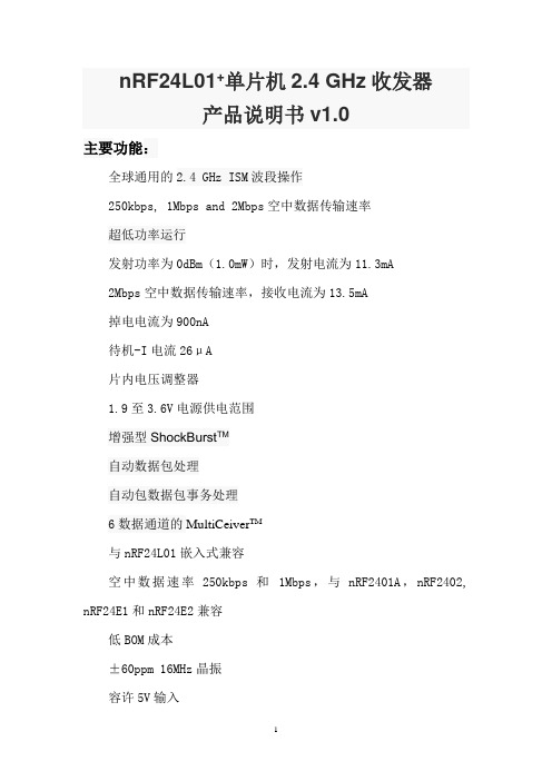
nRF24L01+单片机2.4 GHz收发器产品说明书v1.0主要功能:全球通用的2.4 GHz ISM波段操作250kbps, 1Mbps and 2Mbps空中数据传输速率超低功率运行发射功率为0dBm(1.0mW)时,发射电流为11.3mA2Mbps空中数据传输速率,接收电流为13.5mA掉电电流为900nA待机-I电流26μA片内电压调整器1.9至3.6V电源供电范围增强型ShockBurst TM自动数据包处理自动包数据包事务处理6数据通道的MultiCeiver TM与nRF24L01嵌入式兼容空中数据速率250kbps 和1Mbps,与nRF2401A,nRF2402, nRF24E1和nRF24E2兼容低BOM成本±60ppm 16MHz晶振容许5V输入紧凑的20引脚4x4mm QFN封装应用无线 PC外围设备鼠标,键盘和遥控器三和一桌面捆绑先进的媒体中心遥控器网络电话耳机游戏控制器蓝牙模块运动手表和传感器消费电子产品射频遥控器家庭和商业自动化超低功率无线传感器网络RFID 射频识别资产跟踪系统玩具免责条款北欧半导体ASA有权做出随时更改,提高产品可靠性、功能或设计,不另行通知。
北欧半导体ASA不承担由于应用程序或使用任何所述产品或电路引起的责任。
所有应用程序的信息咨询,不构成说明书的组成部分。
极限值超过一个或多个限制的应力可能会造成设备永久性损坏。
这些应力等级只有在这样或那样的操作环境中提出,在规范中没有给出。
长时间暴露在限制值附近可能会影响设备的可靠性。
生命支持应用这些产品并非为因故障会引起人身伤害的维生装备,设备或系统设计的。
北欧半导体ASA客户使用或出售这些产品,他们将自担风险并同意完全赔偿北欧半导体ASA因使用不当或销售行为造成任何损害。
详细联系方式访问www.nordicsemi.no进入北欧半导体销售办事处和全世界的分销商网站总办公室:Otto Nielsens vei 127004 Trondheim电话: +47 72 89 89 00传真: +47 72 89 89 89www.nordicsemi.no写作惯例本产品规范遵循一套排版规则,文档一致,容易阅读。
超米特电子有限公司产品说明书

1US Headquarters TEL +(1) 781-935-4850FAX +(1) 781-933-4318 • Europe TEL +(44) 1628 404000FAX +(44) 1628 404090Asia Pacific TEL +(852) 2 428 8008FAX +(852) 2 423 8253South America TEL +(55) 11 3917 1099FAX +(55) 11 3917 0817Superior elongation and tensilestrength help to prevent tearing in use due to mishandling. Typical properties for CHO-SEAL 1310 and 1273 materi-al are shown on pages 33 and 32respectively.High Shielding PerformanceCHO-SEAL 1310 material provides more than 80 dB of shielding effectiv-ness from 100 MHz to 10 GHz, while CHO-SEAL 1273 material provides more than 100 dB.Low Volume ResistivityBoth materials have exceptionally low volume resistivity, which makes them well suited for grounding appli-cations in which a flexible electrical contact is needed.Low Compression GasketSpacer gaskets are typicallydesigned to function under low deflec-tion forces. Chomerics uses design tools such as Finite Element Analysis (FEA) to accurately predict compres-sion-deflection behavior of various cross section options. Refer to page16.LCP Plastic SpacerLiquid crystal polymer (LCP)spacers, including those made with Vectra A130 material, provide aCHO-SEAL ®1310 or 1273Conductive ElastomersWith EMI spacer gaskets, shielding and grounding are provided by Chomerics’CHO-SEAL 1310 and 1273 conductive elastomers, specifi-cally formulated for custom shape molded parts. They provide excellent shielding and isolation against electro-magnetic interference (EMI), or act as a low impedance ground path between PCB traces and shielding media. Physically tough, these elas-tomers minimize the risk of gasket damage, in contrast to thin-walled extrusions or unsupported molded gaskets.Silicone-based CHO-SEAL 1310and 1273 materials offer excellent resistance to compression set over a wide temperature range, resulting in years of continuous service. CHO-SEAL 1310 material is filled with silver-plated-glass particles, while 1273 utilizes silver-plated-copper filler to provide higher levels of EMI shielding effectiveness.EMI Spacer GasketsThe unique design of Chomerics’EMI spacer gaskets features a thin plastic retainer frame onto which a conductive elastomer is molded. The elastomer can be located inside or outside the retainer frame, as well as on its top and bottom surface. EMI spacer gaskets provide a newapproach to designing EMI gaskets into handheld electronics such as dig-ital cellular phones. Board-to-board spacing is custom designed to fit broad application needs. Customized cross sections and spacer shapes allow for very low closure forcerequirements and a perfect fit in any design or device.Robotic InstallationSpacer gaskets can be installed quickly by robotic application. Integral locater pins in the plastic spacer help ensure accuratepositioning in both manual and pick-and-place assembly. Benefits include faster assembly and lower labor costs.The integrated conductive elastomer/plastic spacer gasket is a low cost,easily installed system for providing EMI shielding and grounding in small electronic enclosures.Figure 1Single Piece EMI Gasket/Locator PinsCHO-SEAL 1310 or 1273 Conductive Elastomer (Inside)Plastic Spacer Around Outsideor InsideApplications for EMI Spacer GasketsThe spacer gasket concept is especially suited to digital and dual board telephone handsets or other handheld electronic devices. It provides a low impedance path between peripheral ground traces on printed circuit boards and components such as:•the conductive coating on a plastic housing•another printed circuit board •the keypad assemblyTypical applications for EMI spacer gaskets include:•Digital cellular, handyphone and personal communications services (PCS) handsets •PCMCIA cards•Global Positioning Systems (GPS)•Radio receivers•Other handheld electronics, e.g.,personal digital assistants (PDAs)•Replacements for metal EMI shield-ing “fences” on printedcircuit boards in wireless tele-communications devicesstable platform for direct, highprecision molding of conductive elas-tomers. The Vectra A130 material described in Table 1 has excellent heat deflection temperature character-istics (489°F, 254°C). For weight con-siderations, the LCP has aspecific gravity of only 1.61. This plas-tic is also 100% recyclable.Typical EMI Spacer Gasket Design ParametersThe EMI spacer gasket concept can be considered using the design parameters shown in Table 2. Some typical spacer gasket profiles are shown below.Figure 2Typical Spacer Gasket Profiles3US Headquarters TEL +(1) 781-935-4850FAX +(1) 781-933-4318 • Europe TEL +(44) 1628 404000FAX +(44) 1628 404090Asia Pacific TEL +(852) 2 428 8008FAX +(852) 2 423 8253South America TEL +(55) 11 3917 1099FAX +(55) 11 3917 0817Finite Element AnalysisChomerics, a division of the Parker Hannifin Corporation’s Seal Group, is the headquarters of Parker Seal’s Elastomer Simulation Group. This unit specializes in elastomer finite element analysis (FEA) using MARC K6 series software as a foundation for FEA capability.Benefits of FEA include:•Quickly optimizing elastomer gasket designs•Allowing accurate predictions of alternate elastomer design concepts •Eliminating extensive trial and error prototype evaluationTypical use of FEA in EMI spacer gasket designs is to evaluate the force vs. deflection requirements of alternate designs.For example, onespacer design features a continuous bead of con-ductive elastomer molded onto a plastic spacer. An alternative designemploys an “interrupted bead,” where the interrup-tions (gaps left on the plastic frame) are sized to maintain the requiredlevel of EMI shielding. Figure 4illustrates these alternative designs.Gasket DeflectionFigure 5 compares the effect of continuous and interrupted elastomer gasket designs in terms of the force required to deflect the conductive elastomer. This actual cellular handset application required a spacer gasket with interrupted bead to meet desired deflection forces.Chomerics Designand Application ServicesChomerics will custom design a spacer for your application. Advice,analysis and design assistance will be provided by Chomerics Applications and Design engineers at no additional fee. Contact Chomerics directlyat the locations listed at the bottom of the page.Figure 3FEA Example of an EMISpacer Gasket Cross SectionFigure 4Continuous (top) and InterruptedElastomer GasketsFigure 5Typical Spacer Gasket Deflection。
PI168E普传使用说明书
希望用户妥善保管本说明书,这对今后的维护、保养以及其它场合的使用会有所俾益。
注:本说明书凡在型号中出现“9”均示为“8”,如 91R5E3 即为 81R5E3。
目录
第一章 检查与安全注意事项.................................................................................................... 2 第二章 安装................................................................................................................................ 3 第三章 操作键盘与参数设定器................................................................................................ 6 第四章 试运行............................................................................................................................ 8 第五章 功能参数一览表............................................................................................................ 9 第六章 功能参数说明.............................................................................................................. 10 第七章 异常诊断与处理.......................................................................................................... 19 第八章 规范.............................................................................................................................. 20 第九章 保养与检修.................................................................................................................. 23 第十章 任选件.......................................................................................................................... 24 第十一章 品质保证.................................................................................................................. 26
爱森电子产品说明书
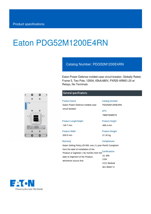
Eaton PDG52M1200E4RNEaton Power Defense molded case circuit breaker, Globally Rated, Frame 5, Two Pole, 1200A, 65kA/480V, PXR20 ARMS LSI w/ Relays, No TerminalsGeneral specificationsEaton Power Defense molded case circuit breakerPDG52M1200E4RN 786679286579139.7 mm 406.4 mm 209.5 mm 21.32 kg Eaton Selling Policy 25-000, one (1) year from the date of installation of theProduct or eighteen (18) months from thedate of shipment of the Product,whichever occurs first.RoHS Compliant UL 489CSACCC MarkedIEC 60947-2Product NameCatalog Number UPCProduct Length/Depth Product Height Product Width Product Weight WarrantyCompliancesCertifications1200 AComplete breaker 5Two-polePD5 Global Class A PXR 20 LSI w/ARMS600 Vac600 VNo Terminals65 kAIC at 480 Vac 100 kAIC Icu/ 100 kAIC Ics/ 220 kAIC Icm @240V (IEC) 15 kAIC Icu/ 7.5 kAIC Ics/ 31.5 kAIC Icm @690V (IEC) 65 kAIC @480/277V (UL) 100 kAIC @240V (UL)70 kAIC Icu/ 53 kAIC Ics/ 154 kAIC Icm @380-415V (IEC) 50 kAIC Icu/ 40 kAIC Ics/ 105 kAIC Icm @440V (IEC) 35 kAIC @600/347V (UL)30 kAIC Icu/ 25 kAIC Ics/ 63 kAIC Icm @525V South Africa (IEC)50 kAIC Icu/ 30 kAIC Ics/ 105 kAIC Icm @480V Brazil (IEC)1200 AEaton Power Defense MCCB PDG52M1200E4RN 3D drawing Power Xpert Protection Manager x64Amperage Rating Circuit breaker frame type Frame Number of poles Circuit breaker type Class Trip TypeVoltage rating Voltage rating - max Terminals Interrupt rating Interrupt rating rangeTrip rating 3D CAD drawing packageApplication notesConsulting application guide - molded case circuit breakersPower Xpert Protection Manager x32BrochuresStrandAble terminals product aidPower Defense brochurePower Defense molded case circuit breaker selection posterPower Defense technical selling bookletCatalogsPower Defense molded case circuit breakers - Frame 5 product aid Power Xpert Release trip units for Power Defense molded case circuit breakersMolded case circuit breakers catalogCertification reportsPDG6 CSA certificationPDG5 CB reportPDG5 CCC certificationPDG5 CSA CertificationPDG6 CCC certificatePower Defense Declaration concerning California’s Proposition 65EU Declaration of Conformity - Power Defense molded case circuit breakersPDG5 UL authorizationInstallation instructionsPower Defense Frame 2/3/4/5/6 voltage neutral sensor module wiring instructions – IL012316ENPower Defense Frame 4_5 flex shaft handle mech assembly instructions - IL012284ENPower Defense Frame 5 aux, alarm, shunt trip and uvr instructions(IL012201EN).pdfPower Defense Frame 5 vertical padlockable handle lock hasp installation instructions - IL012283ENPower Defense Frame 5 key interlock installation instructions -IL012294ENPower Defense Frame 5 walking beam installation instructions -IL012290ENPower Defense Frame 5 breaker status module installation instructions – IL012307ENPower Defense Frame 4_5_6 high performance flex shaft handle mech assembly instructions - IL012296ENInstallation videosPower Defense Frame 5 Trip Unit Replacement Animated Instructions Power Defense Frame 5 UVR Trip How-To VideoPower Defense Frame 5 Aux, Alarm, ST and UVR Animated Instructions.rh1Power Defense Frame 5 Shunt Trip, Aux and Alarm Trip How-To Video Power Defense Frame 5 Trip Unit Upgrade Relays Board, Animated Instructions.rhPower Defense Frame 5 Trip Unit Upgrade Wire Harnesses, Animated Instructions.rhMultimediaPower Defense molded case circuit breakersPower Defense Frame 2 Variable Depth Rotary Handle Mechanism Installation How-To VideoPower Defense Frame 5 Trip Unit How-To VideoEaton Power Defense for superior arc flash safetyPower Defense Frame 6 Trip Unit How-To VideoPower Defense Frame 3 Variable Depth Rotary Handle Mechanism Installation How-To VideoPower Defense BreakersSpecifications and datasheetsEaton Specification Sheet - PDG52M1200E4RNTime/current curvesPower Defense time current curve Frame 5 - PD5White papersMolded case and low-voltage power circuit breaker healthIntelligent power starts with accurate, actionable dataSingle and double break MCCB performance revisited Implementation of arc flash mitigating solutions at industrial manufacturing facilitiesIntelligent circuit protection yields space savingsMaking a better machineSafer by design: arc energy reduction techniquesMolded case and low-voltage breaker healthEaton Corporation plc Eaton House30 Pembroke Road Dublin 4, Ireland © 2023 Eaton. All Rights Reserved. Eaton is a registered trademark.All other trademarks areproperty of their respectiveowners./socialmedia。
TEP-I-C-T说明书

产品概述GZDW 微机型系列高频开关电源直流系统广泛适用于发电厂、变电站,作为高压断路直流操作机构的正常分合闸、继电保护、信号母线等使用的操作电源及事故时分合闸、照明、控制、通信等用的直流电源。
技术要求正常使用条件:•海拔不超过2000m。
•周围空气温度不低于-5℃,不高于+45℃,在设备停用期间,周围空气温度允许为-25℃至+50℃。
•周围空气的最大相对湿度不超过98%(相当于周围空气温度为25℃时)。
•安装地基无振动和冲击,垂直倾度不超过5%。
•运行地点无剧烈导电或爆炸尘埃,没有腐蚀金属和破坏绝缘的气体或蒸气。
•周围空气温度变化率不超过5℃/h,相对温度变化率每小时不超过5%。
•交流电网电压波形为正弦波,电网电压幅值的持续波动范围不超过额定值20%。
•交流电网频率波动范围不超过5%。
•室内使用,且通风良好。
型号命名:电池 G-镉镍蓄电池或电流流电压种类 Q-铅酸蓄电池 M-免维护蓄电池 C-充电柜K-馈电柜Y-充电馈电一体柜柜体含义 D-电池柜J-交流柜主要特性本设备由充电馈电柜(一体柜)和蓄电池柜或充电柜、馈电柜及蓄电池柜等组成。
工作原理•充电浮充电装置采用多个高频开关电源模块并联组成,N+1备份,即在用N个模块满足电池的充电电流(0.1C10)加上经常负荷电流(合闸电流除外)下,选用N+1个模块即可。
如对200AH直流系统:充电电流(0.1×200AH)+ 经常负荷电流(约5A)= 25A选用:TEP-M10/220模块4台即可。
•系统可以选用任何接线型式,其典型接线方式见《GZDW微机自控高频开关电源直流系统典型设计》(泰坦公司)。
•系统输出特性:系统输出特性见图1。
1.均衡充电状态为从图1中A点开始充电,A-B之间的区域为恒流充电区域;2.当蓄电池电压上升至均衡充电电压值B点后设备进入恒压充电工作方式,B-C段为恒定电压区域,均衡充电在给定的时间内结束。
均衡充电结束后,自动转换到浮充电压状态,蓄电池持续在完全充满状态,在D-A段工作。
中讯威易所有产品安装手册

中讯威易安装手册北京中讯威易科技有限公司目录一、ZIGBEE系列 ...................................................................................................................... - 3 -无线门磁<FE-ZB-1001> ..................................................................................................... - 3 - 灯光控制模块<FE-ZB-1004/5> .......................................................................................... - 3 - 红外探测器<FE-ZB-1006> ................................................................................................. - 4 - 无线烟雾感应器<FE-ZB-1007> ......................................................................................... - 4 - 迷你遥控器<FE-ZB-1009> ................................................................................................. - 4 - 二、综合控制网关...................................................................................................................... - 5 -GSM智能网关<FE-IC-1005> ............................................................................................ - 5 - PB电话网关<FE-IC-1006> ................................................................................................ - 5 - 多媒体智能网关<FE-IC-1007> .......................................................................................... - 6 - PB宽带网关<FE-IC-1008> ................................................................................................ - 7 - PLC-IP转换器<FE-IC-1009> ............................................................................................. - 7 - 平安社区综合控制<FE-VS-1002> ..................................................................................... - 8 - 三、PLC-BUS系列 .................................................................................................................. - 14 -加密无线转发器<FE-PB-1003> ....................................................................................... - 14 - 迷你夜光控制器<FE-PB-1005/6> .................................................................................... - 15 - 澳式电器随意插<FE-PB-1010> ....................................................................................... - 16 - 微型灯光控制器<FE-PB-1011/2> .................................................................................... - 16 - 学习型红外控制器<FE-PB-1016> ................................................................................... - 17 - 水晶面板控制器<FE-PB-1017/8> .................................................................................... - 18 - 窗帘控制器<FE-PB-1019> ............................................................................................... - 19 - 信号综合分析仪<FE-PB-1023> ....................................................................................... - 19 - 三相信号耦合器<FE-PB-1024> ....................................................................................... - 19 - 四、安防系列............................................................................................................................ - 20 -红外探测器<FE-PB-S1001> ............................................................................................. - 20 - 彩信眼<FE-GS-1001> ....................................................................................................... - 20 - 五、视频监控............................................................................................................................ - 21 -网络摄像机<FE-EC-1008> ............................................................................................... - 21 -六、背景音乐系统.................................................................................................................... - 22 -七、调试.................................................................................................................................... - 27 -八、常见问题............................................................................................................................ - 28 -中讯威易智能家居安装指导在安装之前,准备工作一定要做好。
INP-TN5A0072-E 无纸机通信功能(以太网)类型:PHF 说明书
亿佰特-E07系列-CC1101无线模块-发射功率10dBm-E07-915MS10用户手册
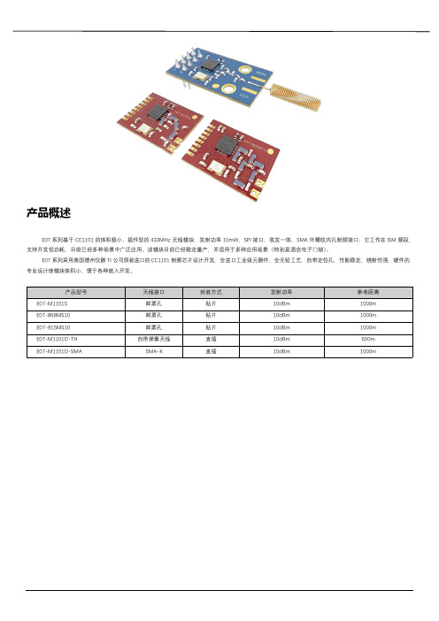
产品概述E07系列基于CC1101的体积极小、插件型的433MHz无线模块,发射功率10mW,SPI接口,收发一体,SMA外螺纹内孔射频接口,它工作在ISM频段,支持开发低功耗,目前已经多种场景中广泛应用。
该模块目前已经稳定量产,并适用于多种应用场景(特别是酒店电子门锁)。
E07系列采用美国德州仪器TI公司原装进口的CC1101射频芯片设计开发,全进口工业级元器件,全无铅工艺,自带定位孔,性能稳定,绕射性强,硬件的专业设计使模块体积小,便于各种嵌入开发。
目录产品概述 (1)目录 (2)1.技术参数 (3)1.1.通用参数31.2.电气参数31.2.1.发射电流 (3)1.2.2.接收电流 (3)1.2.3.关断电流 (3)1.2.4.供电电压 (4)1.2.5.通信电平 (4)1.3.射频参数41.3.1.发射功率 (4)1.3.2.接收灵敏度 (4)1.3.3.推荐工作频率 (4)1.4.距离测试52.机械特性 (5)2.1.E07-M1101S/E07-868MS10/E07-915MS1052.2.E07-M1101D-TH/E07-M1101D-SMA63.生产指导 (7)3.1.回流焊温度73.2.回流焊曲线图74.常见问题 (7)4.1.通信距离很近74.2.模块易损坏85.重要声明 (8)6.关于我们 (8)1.技术参数1.1.通用参数1010101010 1.2.电气参数1.2.1.发射电流1.2.2.接收电流1.2.3.关断电流1.2.4.供电电压1.2.5.通信电平1.3.射频参数1.3.1.发射功率1.3.2.接收灵敏度1.3.3.推荐工作频率1.4.距离测试2.机械特性2.1.E07-M1101S/E07-868MS10/E07-915MS102.2.E07-M1101D-TH/E07-M1101D-SMA3.生产指导3.1.回流焊温度●预热区:最大升温为2.5℃/s;●保温区:温度150~190℃,时间为60~90s,最大升温为2.5℃/s;●回流区:最高温度为235~245℃,217℃以上时间为40~80s;●冷却区:最大降温为4℃/s。
威лен电子公司 SpitFire TIR3 LED控板仪说明书
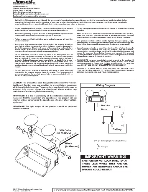
For warranty information regarding this product, visit /warranty©2017 Whelen Engineering Company Inc.Form No. 14A58 (010517)SpitFire™TIR3 LED Dash LightCAUTION!This product has been designed to rest on top of the vehicle'sdashboard.Suction cups are provided to prevent lateral movementwhile the vehicle is in motion.These suction cups should not be used tosuspend this product above the dashboard.Clean suction cupmounting surface thoroughly before mounting.IMPORTANT!It is the responsibility of the installation technician tomake sure that the installation and operation of this product will notinterfere with or compromise the operation or efficiency of any vehicleequipment!IMPORTANT!The light output of this product should be projectedparallel to the road.Safety First: This document provides all the necessary information to allow your Whelen product to be properly and safely installed. Beforebeginning the installation and/or operation of your new product, the installation technician and operator must read this manual completely.Important information is contained herein that could prevent serious injury or damage.!Proper installation of this product requires the installer to have a good understanding of automotive electronics,systems and procedures.!Whelen Engineering requires the use of waterproof butt splices and/or connectors if that connector could be exposed to moisture.!Failure to use specified installation parts and/or hardware will void theproduct warranty!!If mounting this product requires drilling holes,the installer MUST be sure that no vehicle components or other vital parts could be damaged by the drilling process.Check both sides of the mounting surface before drilling begins.Also de-burr any holes and remove any metal shards or remnants.Install grommets into all wire passage holes.!Do not install this product or route any wires in the deployment area of your air bag.Equipment mounted or located in the air bag deployment area will damage or reduce the effectiveness of the air bag,or become a projectile that could cause serious personal injury or death.Refer to your vehicle owner's manual for the air bag deployment area.The User/Installer assumes full responsibility to determine proper mounting location,based on providing ultimate safety to all passengers inside the vehicle.!For this product to operate at optimum efficiency,a good electrical connection to chassis ground must be made.The recommended procedure requires the product ground wire to be connected directly to the NEGATIVE (-)battery post.!Do not attempt to activate or control this device in a hazardous driving situation.!If this product uses a remote device to activate or control this product,make sure that this control is located in an area that allows both the vehicle and the control to be operated safely in any driving condition.!This product contains either strobe light(s),halogen light(s),high-intensity LEDs or a combination of these lights.Do not stare directly into these lights.Momentary blindness and/or eye damage could result.!Use only soap and water to clean the outer e of other chemicals could result in premature lens cracking (crazing)and discoloration.Lenses in this condition have significantly reduced effectiveness and should be replaced immediately.Inspect and operate this product regularly to confirm its proper operation and mounting condition.Do not use a pressure washer to clean this product.!WARNING!All customer supplied wires that connect to the positive (+)terminal of the battery must be sized to supply at least 125%of the maximum operating current and “at the battery”to carry that FUSED load.DO NOT USE CIRCUIT BREAKERS WITH THIS PRODUCT!!FAILURE TO FOLLOW THESE PRECAUTIONS AND INSTRUCTIONS COULD RESULT IN DAMAGE TO THE PRODUCT OR VEHICLE AND/OR SERIOUS INJURY TO YOU AND YOURPASSENGERS!®ENGINEERING COMPANY INC.51 Winthrop RoadChester, Connecticut 06412-0684Phone: (860) 526-9504SalesEmail:*******************CanadianSales:************************CustomerService:*******************Warnings to InstallersWhelen’s emergency vehicle warning devices must be properly mounted and wired in order to be effective and safe. Read and follow all of Whelen’s written instructions when installing or using this device. Emergency vehicles are often operated under high speed stressful conditions which must be accounted for when installing all emergency warning devices. Controls should be placed within convenient reach of the operator so that he can operate the system without taking his eyes off the roadway. Emergency warning devices can require high electrical voltages and/or currents. Properly protect and use caution around live electrical connections.Grounding or shorting of electrical connections can cause high current arcing, which can cause personal injury and/or vehicle damage, including fire. Many electronic devices used in emergency vehicles can create or be affected by electromagnetic interference.Therefore, after installation of any electronic device it is necessary to test all electronic equipment simultaneously to insure that they operate free of interference from other components within the vehicle. Never power emergency warning equipment from the same circuit or share the same grounding circuit with radio communication equipment.All devices should be mounted in accordance with the manufacturer’s instructions and securely fastened to vehicle elements of sufficient strength to withstand the forces applied to the device. Driver and/or passenger air bags (SRS) will affect the way equipment should be mounted.This device should be mounted by permanent installation and within the zones specified by the vehicle manufacturer, if any.Any device mounted in the deployment area of an air bag will damage or reduce the effectiveness of the air bag and may damage or dislodge the device. Installer must be sure that this device, its mounting hardware and electrical supply wiring does not interfere with the air bag or the SRS wiring or sensors. Mounting the unit inside the vehicle by a method other than permanent installation is not recommended as unit may become dislodged during swerving; sudden braking or collision. Failure to follow instructions can result in personal injury. Whelen assumes no liability for any loss resulting from the use of this warning device. PROPER INSTALLATION COMBINED WITH OPERATOR TRAINING IN THE PROPER USE OF EMERGENCY WARNING DEVICES IS ESSENTIAL TO INSURE THE SAFETY OF EMERGENCY PERSONNEL AND THE PUBLIC.Warnings to UsersWhelen’s emergency vehicle warning devices are intended to alert other operators and pedestrians to the presence and operation of emergency vehicles and personnel. However, the use of this or any other Whelen emergency warning device does not guarantee that you will have the right-of-way or that other drivers and pedestrians will properly heed an emergency warning signal. Never assume you have the right-of-way. It is your responsibility to proceed safely before entering an intersection, driving against traffic, responding at a high rate of speed, or walking on or around traffic lanes. Emergency vehicle warning devices should be tested on a daily basis to ensure that they operate properly. When in actual use, the operator must ensure that both visual and audible warnings are not blocked by vehicle components (i.e.: open trunks or compartment doors), people, vehicles, or other obstructions. It is the user’s responsibility to understand and obey all laws regarding emergency warning devices.The user should be familiar with all applicable laws and regulations prior to the use of any emergency vehicle warning device. Whelen’s audible warning devices are designed to project sound in a forward direction away from the vehicle occupants. However, because sustained periodic exposure to loud sounds can cause hearing loss, all audible warning devices should be installed and operated in accordance with the standards established by the National Fire Protection Association.。
ENTTEC PIXIE 产品说明书
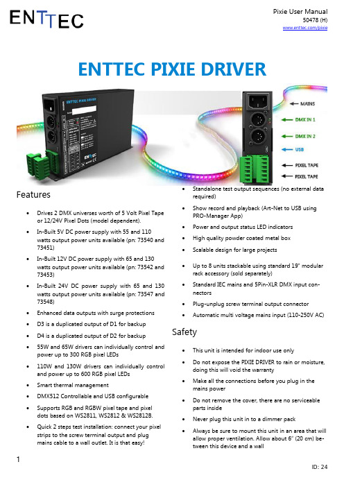
50478 (H)/pixieENTTEC PIXIE DRIVERFeatures∙Drives 2 DMX universes worth of 5 Volt Pixel Tape or 12/24V Pixel Dots (model dependent).∙In-Built 5V DC power supply with 55 and 110 watts output power units available (pn: 73540 and73451)∙In-Built 12V DC power supply with 65 and 130 watts output power units available (pn: 73542 and73453)∙In-Built 24V DC power supply with 65 and 130 watts output power units available (pn: 73547 and73548)∙Enhanced data outputs with surge protections∙D3 is a duplicated output of D1 for backup∙D4 is a duplicated output of D2 for backup∙55W and 65W drivers can individually control and power up to 300 RGB pixel LEDs∙110W and 130W drivers can individually control and power up to 600 RGB pixel LEDs∙Smart thermal management∙DMX512 Controllable and USB configurable∙Supports RGB and RGBW pixel tape and pixel dots based on WS2811, WS2812 & WS2812B.∙Quick 2 steps test installation: connect your pixel strips to the screw terminal output and plugmains cable to a wall outlet. It is that easy!∙Standalone test output sequences (no external data required)∙Show record and playback (Art-Net to USB using PRO-Manager App)∙Power and output status LED indicators∙High quality powder coated metal box∙Scalable design for large projects∙Up to 8 units stackable using standard 19” modular rack accessory (sold separately)∙Standard IEC mains and 5Pin-XLR DMX input con-nectors∙Plug-unplug screw terminal output connector∙Automatic multi voltage mains input (110-250V AC) Safety∙This unit is intended for indoor use only∙Do not expose the PIXIE DRIVER to rain or moisture, doing this will void the warranty∙Make all the connections before you plug in the mains power∙Do not remove the cover, there are no serviceable parts inside∙Never plug this unit in to a dimmer pack∙Always be sure to mount this unit in an area that will allow proper ventilation. Allow about 6” (20 cm) be-tween this device and a wall50478 (H) /pixiePower-supply cords should be routed so that they are not likely to be walked on or pinched byitems placed upon or against them, paying partic-ular attention to the point they exit from the unit Start-Up Demo InstallationThe PIXIE Driver comes loaded with a scrolling rainbow demo sequence which will run and loop every time you power the unit up so you can get your installation tested straight away once you connect your LED pixel strips. When any valid data is fed through the DMX or USB ports it will override the demo playback sequence and keep lis-tening to the data ports until you re-power the unit.If you do not want the PIXIE driver to generate any output when powered up, it can be done by erasing the pre-loaded show or overwriting it with your own as further de-scribed in the ENTTEC PRO Manager software section.Power BudgetingThis section explains how many Dots or LEDs can be con-nected to the unit.Please note that the 55W and 65W mod-els have only one power supply (VCC) and the VCC0 output will not be available.Warning: (VCC and VCC0) cannot be connected in paral-lel.Pixel Strips and Pixel TileThe strips/tile supported by the PIXIE driver are based on the WS2811, WS2812 and WS2812B protocol.The following table shows the maximum number of LEDs that the driver can power when driven to the max. (RGB channels on 100% or white).300 RGB LEDs can be substituted for 240 RGBW LEDs in the above table.Pixel DotsThe dots supported by the PIXIE driver are based on the WS2811, WS2812 and WS2812B protocol.Regardless of the output power (65w or 130W) and output voltage (12V or 24V), any PIXIE drivers can process 1024 DMX channels. However, since Pixel Dots have much higher light output compared to Pixel strip, this leads to the higher power consumption.This limits the number of dots that a driver can control, and can be calculated by: dividing the total output of driver with the output of each dot. For example,drivers will suit your application when one driver is not enough.Warning: Overloading the outputs could cause the driver and the connected strips to malfunction or flicker. Status LEDThe Pixie driver comes with two LED indicators located in the front panel.The orange LED indicates that the internal power supply is working properly and the unit is ready to operate and sup-ply power to the strips. If the LED is OFF and you have al-ready connected the mains cable to a working wall outlet, it means that there is a problem in the unit. In such case please contact ENTTEC support.The green LED indicates the PIXIE status and should be constantly flashing. Please refer to the following table forothers. A general explanation of all the modes is made in this chapter and you can find further information on how to use and configure the settings in the ENTTEC Pro Man-ager software section.USBThe USB 2.0 port is mainly used to configure the unit and download new shows. It also allows sequences to be run through the free application as described in the Pro Man-ager software section.When running the sequences all other modes will be over-ridden by the USB port as it has the highest precedence. DMX modeWhen data is fed through the DMX ports and there is no active USB sequence, this will be reflected on the strips outputs D1 and D2.By default the data coming from DMX1 connector will be sent to the beginning of the strips (section 1) through D1 and D2 outputs and the data coming from DMX2 will be sent to sec-tion 2 through both outputs.The full DMX LED strip update message format is shown be-low for RGB Pixel Tape. If the DMX message has less than 510 slots other than the start code, the data for missing slots will be zero. The full DMX LED strip update message format is shown be-low for RGBW Pixel Tape. Full 512 DMX slots are used when Pixie driver is in RGBW modes. Playback modeTrigger the stored show from the Pro Manager software or by configuring the PIXIE to start playing it on power up.The PIXIE driver comes with a pre-loaded scrolling rainbow sequence which will playback and loop forever on power up. More sequences can be recorded or loaded using PRO-Manager App. The maximum length of the sequence de-pends on the recording parameters.E.g. The shortest possible show with 510 channels at 40 frames per second, will be 25 seconds. If the show has a repetitive nature you could also get it to loop-back forever. Remember that any data coming from DMX or USB ports will override the playback mode.Reference DesignPIXIE driver supports any kind of DMX output device. Here is a reference diagram of connections.PRO-MANAGERENTTEC provides a free cross-platform (Windows & Mac only) application to configure, test and update the PIXIE. It also al-lows the user to record an Art-net show into the memory and set-up the standalone mode. The application is available for Windows or Mac from the ENTTEC website.When connected by usb, it should be correctly identified as ENTTEC PIXIE Driver by your computer. Please install and run PRO-Manager with the Pixie driver connected.“Devices” TabFrom the PRO Manager Home page, you can click the “Find Devices” button to search for ENTTEC devices connected to your computer. Once it finds it, please select the PIXIE from the selection box to start communication.Once selected, you will see all the device information on the Home Page, from here you can configure Settings and up-date the firmware on the PIXIE.Firmware UpdateUse the latest firmware file meant for PIXIE driver available on the ENTTEC website (/pixie ) and upload it using the upload button (“Choose File” - as per Chrome browser).After selecting the correct file, click on the Update Firm-ware button and let the update proceed.Once finished, the page will automatically refresh, and de-vice information will be updated to reflect the updated firmware.Pixie SettingsDMX PersonalityPersonality options decide the flow of DMX.Personality1: Both outputs (D1 & D2) are mapped to-gether to both DMX inputs. DMX1 drives section1 and DMX2 drives section2 of both the outputs.Personality2: DMX1 is mapped to D1 only, and DMX2 ismapped to D2 only.Additional setting for Personality2, allows the physical LED pixels to be grouped onto desired number of DMX pixels.LED Strip protocolAllows compatibility amongst the supported protocols (WS2811, WS2812, and WS2812B). Please check your strip to see which protocol it supports.Run show on DMX lossIf standalone show is programmed onto Pixie, and this option is set to Yes and, if no DMX input is received, the show will be played back. (3 seconds timeout for DMX input)Pixel OrderingAllows the order of Pixel mapping to be changed on the Pixie, usually to conform to the pixel ordering of the LED. This set-ting applies to all input data sources: DMX, USB, and show replay.The default ordering assumes that both the DMX input and the led strip outputs are in RGB order.RGB Ordering modes will map every Pixel to 3 DMX Slots. RGBW Ordering modes will map every Pixel to 4 DMX Slots. For example, to use ENTTEC RGBW Pixel Tape with your Pixie driver, you will set the ordering to GRBW. “SEND” TabIt is possible to send pre-defined testing sequences, personalized data or Art-Net packets coming from any external source to your strips using the tools provided in this window.Select one out of the three available sources: “Test Patterns”, “Live Art -net” or “From Faders”. Then select the Output con-figuration depending on your particular wiring need.The Test Patterns mode will start sending predefined se-quences to your strips once you select the desired one from the drop down.50478 (H)/pixieThe Live Art-Net section will allow the user to send any in-coming valid Art-Net data straight to the pixel strips whilstthe pro manager is running and a USB cable is connected.Please select the matching start universe and make surethe Art-net data is being sent to your computer IP addressor broadcasted.PRO-Manager will show the mapping from universe to sec-tions on each output, based on your selections.Closing or changing the Send window, will stop Art-Net to Pixie send, PRO-Manager only sends to Pixie while on this page.Finally, data can be sent to any particular pixel by using the channel faders which allow you to adjust the intensity of any desired LED on the strip.“Standalone” TabStandalone mode allows you to record (and playback) shows via Art-Net input to PIXIE memory. The duration of the recording depends on the configuration selected be-fore recording. The recorder is smart enough to only rec-ord changes in the frames, so as to accommodate as many frames as possible.The recording trigger feature will let you select a channel in your show to start/stop the recording when it is greater than a selected value. Once the configuration is all set, you can click on “Record Art-Net” button to start recording the show.The recording is saved to a file, and is only transferred to the memory when recording is stopped by using the “Stop Re-cording” button or driving the trigger channel to the right value. Whilst recording, live data is sent to the strips, so you can decide when to stop.The recording can now be transferred to memory using “Write to Memory” button and the upload t o memory progress is shown as it happens.Once the show is uploaded to memory successfully, the page is automatically refreshed to allow show control on the rec-orded show.The show can now be played and stopped using the controls on this page. These controls will only be available, if there is a show stored in memory.You can also export and import recorded shows using the “Ex-port Show to File” or “Import Show to PIXIE Driver” buttons.Thermal ManagementPIXIE driver (revB onwards) has an in-built thermal control system. It constantly monitors the hardware’s internal tem-perature and acts on the condition of overheating. When internal temperature is higher than the limit (as shown in the chart below), the thermal control system will gradually lower the intensity of the connected strips or dots to cool down the driver. Once the internal tempera-ture is within the limit, the driver will resume its normal op-eration.Application Usage ExamplesExample1: Drive 300 leds from 1 DMX UniverseStrip used: 8PL-60-F (5M of Smart Pixel Tape)Pixie is setup to use DMX Personality2, with pixel group-ing set to 2.This setup allows you to map 450 channels of DMX to 300LEDs (each RGB DMX address is mapped to 2 pixel LEDs)Example2: Drive 300 leds from DMX1 & DMX2Strip used: 8PL-60-F (5M of Smart Pixel Tape)Pixie is setup to use DMX Personality1This setup allows you to map DMX1 to the first section (170leds) and DMX2 to the second section (remaining 130 leds) –allowing upto 300 leds in totalPhysical DimensionsThe unit is designed to fit the modular rack accessory (soldseparately) which allows stacking up to 8 units in a standard19” rack using 3 standard rack mount units (3RU).SpecificationsDue to continuous improvements and innovations of all ENTTEC products, specifications and features are subject to change without notice.Ordering InformationStackable Modular Rack (Accessory)The modular rack (PN: 73550 - sold separately) allows up to 8 Email:**************** Website: 。
EATON 电子熔断器系列C的电子熔断器与DIGITRIP RMS 系列的说明书

Master Connection Diagram Series C R-Frame Circuit Breaker with DIGITRIP RMS Trip Units1Instruction Leaflet IL29C714LEffective October 2012Master Connection Diagram Series C R-Frame Circuit Breaker with DIGITRIP RMS T rip UnitsEATON CORPORATIONLINEREV.123610 18101910/750/1050INDEX DIAGRAMSTRIP UNIT AND ACCESSORY MOUNTING LOCATIONS TERMINATION DIAGRAM22CONNECTIONS FOR RMS 700180023241232225A B C D E 8101910/750/1050MOTOR OPERATOR CONNECTIONCONTROL F G H I J K L M N 2324RD BREAKER GROUND FAULT AND REFERENCESFRAME INSTRUCTIONSRMS 500AUXILIARY SWITCHALARMSWITCH SHUNT0P25I.L.NO.UNDERVOLTAGE RELEASE LOW ENERGY SHUNT MOTOR OPERATOR TERMINAL BLOCKRMS 600RMS 700RMS 800RMS IN SERIES C FRAME RMS 5101129-8521129-8531129-854RD MASTER CONNECTION DIAGRAM INDEXRMS 610RMS 810RMS 3101129-8861129-8882627RD MASTER CONNECTION DIAGRAM Cat No. EOPTOBC CD BLOCK CONNECTION2627RD MASTER CONNECTION DIAGRAM - RG310+ Trip Unit2Instruction Leaflet IL29C714LEffective October 2012Master Connection Diagram Series C R-Frame Circuit Breaker with DIGITRIP RMS T rip UnitsEATON CORPORATION STABINDEDICATED'b'CONTACTINTERNALLY ONRHS810750,910 &MODULERMSDIELECTRICENERGY SHUNTNOTE:THE MAXIMUM NUMBER OF ACCESSORIES THAT MAY BE INSTALLED IN ANY ONE CIRCUIT BREAKER I S LIMITED BY THE NUMBER OF PHYSICAL MOUNTING POSITIONS.RD MASTER CONNECTION DIAGRAM T RIP U NIT AND A CCESSORY M OUNTING L OCATIONS9103Instruction Leaflet IL29C714LEffective October 2012Master Connection Diagram Series C R-Frame Circuit Breaker with DIGITRIP RMS T rip UnitsEATON CORPORATION CODED LEADBLOCKITYPICAL LEAD TERMINATIONRD MASTER CONNECTION DIAGRAMT E R M I N A T I O N D I A G R A MTERMINAL FOR TRIP FOR ACCESSORYCONNECTIONS ONLYCONNECTIONS ONLYFRONT FIXED SIDE SECONDARY SECONDARY CONNECTORS FUR TRIP FOR ACCESSORY TERMINATION C COLOR CODEDVIEW MOUNTEDTYPICAL LEAD TERMINATIONMOUNTED BREAKER PIN WAMP 'MULTIMATE'TYPE P/N 66099-4'MULTIMATE'A90067-4FOR EXTRACTION305183TYPICAL DISCDNNECT AS VIEWED FROM BTERMINAL BLOCKSCONNECTIONS ONLYCONNECTIONS WIRING MALE FEMALE HANDCRIMP4Instruction Leaflet IL29C714LEffective October 2012Master Connection Diagram Series C R-Frame Circuit Breaker with DIGITRIP RMS T rip UnitsEATON CORPORATION CRTOP1I FLUXISHUNT TRIPIWHT+AII II II RMSII III I I IWHTI III III IBLKII IIWHTIIIIIBLKII IIWHTI I IIII I 1110I III I I IISEE19AND NOTE 2ONB R E A K E R S EQUIPPED WITHAFAULT17TIME310TRIPUNIT.I N C L U D EAN D 9,CIRCUIT NOT FOR USE ONSCRRD MASTER CONNECTIONDIAGRAMRMS N O N -G R O U N D F A U L T T R I P U N I T CONNECTIONSA B R E A K E R S5Instruction Leaflet IL29C714LEffective October 2012Master Connection Diagram Series C R-Frame Circuit Breaker with DIGITRIP RMS T rip UnitsEATON CORPORATIONLC RTOP END--------------------------IIENDBASIC BREAKER INTERNAL CONNECTIONS(PARTIALONLY)EXTERNAL SHORTING STRAPS M U STDURINGSHEET 18A N DNOTE SHEET17TESTING ANDOPERATING GFP ZONEINTERLOCKINGC4,N.P.SIDE BREAKERRD MASTER CONNECTION DIAGRAMRD W I TH RMS U NIT -G ROUND F AULT E XTERNAL CONNECTIONS B REAKERS6Instruction Leaflet IL29C714LEffective October 2012Master Connection Diagram Series C R-Frame Circuit Breaker with DIGITRIP RMS T rip UnitsEATON CORPORATION BREAKER STYLESENSOR RATINGRATINGFLUX IBOTTOMENDEXTERNAL SHORTINGSTRAPSBEPLACENO.14OR N O.PERAND OPERATINGPERO N NEUTRALSENSORCDNNCTIONS.NP.SIDEBREAKERNEUTRAL SENSOR RATIO M U S T MATCHSENSORSBREAKERNEUTRALSO THAT POLARITYRELATIONSHIPTOWARDSI SIDENTICALSHEET 18A ND1SHEET 17F ORNEUTRALZONEC4,RD MASTER CONNECTION DIAGRAMRD RMS U NIT -G ROUND F AULT E XTERNAL CONNECTIONS RESIDUAL B REAKERSFRAMEብ7Instruction Leaflet IL29C714LEffective October 2012Master Connection Diagram Series C R-Frame Circuit Breaker with DIGITRIP RMS T rip UnitsEATON CORPORATIONBREAKERNEUTRAL STYLEFRAMESENSOR RATING RATINGAMPSLC R TOP END12500IELECTRODEIGFPT.B.EXTERNAL SHORTING STRAPS MUST BE I N PLACEDURING NO.14OR NO.12COPPER WIRE PER I.L.1053TESTING ANDOPERATING PERINSTRUCTIONNEUTRAL SENSORSECONDARYSIDE BREAKERNEUTRAL SENSOR RATIO MUSTMATCHI N BREAKER FRAMEN E U T R A L S E N S O R S O T H A T P O L AR I TYTOWARDS SOURCE I SIDENTICALSHEET 18AND NUTE 1ON SHEET 17FORFIRAND NEUTRAL SENSORSGFPINTERLOCKINGC4,RD MASTER CONNECTIONDIAGRAMRD W I TH RMS U NIT -G ROUND F AULT E XTERNAL C ONNECTIONS 3PH S OURCE GROUND B REAKERSAMPSብ8Instruction Leaflet IL29C714LEffective October 2012Master Connection Diagram Series C R-Frame Circuit Breaker with DIGITRIP RMS T rip UnitsEATON CORPORATION SHUNT TRIP,A\\:.,A>RESIDUALSENSING.,A..WO ND7NADS TOA N DSHEETD8F OURGFPSENSING.BLDCKALSO SHEETRD MASTER CONNECTIONDIAGRAM C URRENT S ENSOR C ONNECTIONS FOR(U SE RMS)9Instruction Leaflet IL29C714LEffective October 2012Master Connection Diagram Series C R-Frame Circuit Breaker with DIGITRIP RMS T rip UnitsEATON CORPORATION RD MASTER CONNECTION DIAGRAM3P OLE RD W I TH RMS U NIT -N EUTRAL P ROTECTEDC ONNECTIONS,B REAKERSAI SHUNT.I IIII II IWHTII I IvENDBREAKERCONNECTIONSCPARTIAL ONLY)MUST B EMARKED:II II IIISHUNT TRIPWHT (+) 15RD MASTER CONNECTION DIAGRAM4P OLE RD W I TH RMS U NIT N EUTRAL P ROTECTEDCONNECTIONS B REAKERSTABCDSHUNT TRIPI I II II --------------I II II I II310,510,810,910I750,AND 1050II IICIRCUITAB C DBOTTOMNO.OFCAT.NO.SWITCHESA1RD MASTER CONNECTION DIAGRAMA LARM (S IGNAL)L OCKOUT S WITCH CONNECTIONSB8B12bPREFERREDFIG.AFIG.BB4B5A 7A 8A9A11A12bFIG.CFIG.DA l l A12b FIG.ETHE MAXIMUMNUMBER ACCESSORIES THAT MAY BE INSTALLED IN A N Y ONE CIRCUIT BREAKER I S LIMITED BY THE NUMBER OFPHYSICAL POSITIONS.B6A7A 8S TPREFERREDWHTFIG.AWHTFIG.CA9A10STA5A 6>-STTHE MAXIMUM NUMBER O F TVO SHUNT TRIPS MAY BE INSTALLED I N ANY O N E CIRCUIT BREAKER,RD MASTER CONNECTION DIAGRAMS HUNT T RIP C ONNECTIONSPREFERREDFIG.A F I G.A9A1FIG,BA5A6FIG.NOTE:THE MAXIMUM NUMBER OF TWO UVRS MAYBE INSTALLED I N ANY ONE CIRCUITBREAKER.RDMASTER CONNECTION DIAGRAMR ELEASE C ONNECTIONSRD MASTER CONNECTION DIAGRAMLow E NERGY S H U NTA7AS PREFERRED FIG.AA9A10F IG .BA3A4LEST FIG.CA5A6LESTTHE MAXIMUMNJMBER OF ACCESSORIES THAT MAY BEINSTALLEDANY ONECIRCUIT BREAKER ISBYNUMBERPOSITIONS.I T I CLOSEDI r--------II RD FRAMEIIMOTORI OPERATORIIUIIIIIIII I II IX AUX.R E L A Y LEGEND1TRANSFORMER MAY BEBREAKER AUX.Y RELAY b BREAKER SWITCHRE Q UIRED L Y-O NAND MOTOR CONTACTS SHOWN I N OPEN RESET I S-MOTOR OPERATOR TERMINAL BLOCKRD MASTER CONNECTION DIAGRAMM OTOR O PERATOR C ONNECTIONSALL RD BREAKERS EQUIPPED WITH DIGITRIP RMS500,600,700,800,510,610,810,910,750,AND1050TRIP UNITS WITH G F P WILL TRIP NEAR INSTANTANEOUSLY(0.04-0.12 SEC.)REGARDLESS OF THE TIME BAND SETTING-IF DUWNSTREAM INTERLOCK WIRING I S NOT EMPLOYEDA JUMPER I S NOT ADDED BETWEEN CONTROL TERMINALS C4AND WITH THE JUMPER ADDED,THE BREAKER WILL RESPOND TOTHE PRE-SET TIME DELAY SETTING.CONSIDER ADDING THIS JUMPERFOR ALL INSTALLATIONS WITH GFP ON THE MAIN BREAKER ONLY.INSTALLATIONS WITH MULTIPLE LEVELS OF GFP,SEE SHEET2.ALL RD BREAKERS EQUIPPED WITH RMS500,600,700, 800,510,610, 810, 910,750AND1050TRIP UNITS EQUIPPED WITH AN ADJUSTABLE: SHORT TIMEDELAY SETTING WILL TRIP NEAR INSTANTANEOUSLY(0.04-0.12REGARDLESS OF THE TIME BAND SETTING-IF DOWNSTREAM INTERLOCK WIRING I S EMPLOYED AND/OR A JUMPER I S NOT ADDED BETWEENCONTROL TERMINALS D9WITH THE JUMPER ADDED,THE BREAKERWILL RESPOND TO THE PRE-SET TIME DELAY SETTING.FOR SELECTIVE CDORDINATIDN,INTERLOCK WIRING BE EMPLOYED.SEE SHEET3,RD-BREAKERS HAVE BEEN DESIGNED FOR MAXIMUM PROTECTION,COMMUNCATIONS AND ACCESSORY UTILIZATION.THIS REASON ALL LEADS I N THE SECONDARY CONTROL BLOCKS MAY NOT BE USED BY A CUSTOMER FOR A PARTICULAR APPLICATION.WARNINGBREAKER AUTOMATIC OPEN AND CLOSE OPERATIONS BY INCOMCDMMUNICATION SIGNALS(V I A TERMINALS AND UNDERSYSTEM OPERATING OR MAINTENANCE PERIODS CAUSESEVERE INJURY DEATH,INSTALL APPROPRIATEPERMISSIVE MEANS(SEE SHEETAVOID UNDESIRED CLDSING DURING MAINTENANCEOPERATIONS AND PRDVIDE ADEQUATE EQUIPMENT WARNINGSFOR NORMAL PERIODS.RD MASTER CONNECTION DIAGRAMG E N E R A L N OTESJUMPER MUST BE ADDED ON EACH DOWN STREAM BREAKERWHERE D E L A Y PRE -SET REQUIRED.SEE ALSO NOTE '1SHEET '17.AND RUN SEPARATEFROM POWERCABLESPERA MAXIMUM DISTANCE BETWEEN THE FIRST AND LAST ZONE IS 250FEETAOF20MAYCONNECTEDINPARALLEL ZONE3EMPLOYEDSELF -INTERLOCK.A MAXIMUM OF20MAY BE CONNECTEDINSIGNAL DIODES TYPE1ORAS SHOWN IN 3ALTERNATE.A MAXIMUM OF 5BREAKERS M A Y BECONNECTEDZONE 3WHEN EMPLOYED SELF -INTERLOCK.ZONECONSIDERATIONS MUST6B EO N(D U A L S O U R C E )O RDISTRIBUTION SYSTEMS TOSEQUENCES.C4OUTPUTC O M M O NRD MASTER CONNECTION DIAGRAM T Y P I C A L G ROUND F AULT Z ONE I NTERLOCKINGC ONNECTIONS FOR R ADIALD ISTRIBUTION S YSTEM(U SE W I TH RMS E Q UIPPED W I T H G ROUND F UNCTION )18ቧቢJUMPER MUST BE ADDED ON EACH D O W N STREAM BREAKERNOTE2SHEET17.A N D R U N S E P A R A T E FROMOR COPPER WIRE6REQUIRED PER UL-1053A MAXIMUM DISTANCE BETWEENTHE FIRST AND LAST ZONE IS 250FEET.A MAXIMUM OF20MAY BE CONNECTEDIN PARALLEL ZONEA MAXIMUM OF20BREAKERSEMPLOYED SELF-INTERLOCKSIGNAL DIODES OR EQUIVALENTA MAXIMUM OF5BREAKERSMAY CONNECTEDIN PARALLEL IN ZONE3SELF-INTERLOCK.OUTPUTCOMMONRD MASTER CONNECTION DIAGRAMSC ONNECTIONS FOR R ADIALD ISTRIBUTION S YSTEM(U SE WITH DIGITRIP RMSE Q UIPPED WITH S H O RT D ELAYF UNCTION)20 EATON CORPORATION 21EATON CORPORATION 22EATON CORPORATION V VVASELECTRIC OPERATOR FUNCTIONREQUIRED 700,800,810,910,ANDREMOTELY CLOSEVIA INCOM.IFOPERATORNOT SUPPLIED,RED ANDSEE S H E E T 23.BLUEBE PRESENTBUTCONNECTED.PT MODULE ISNOTTYPERD MASTER CONNECTIONDIAGRAMC ONNECTIONS FORUSERMS 700,800,810,910,750,AND 10504ICLOSE(O P T IONAL)(OPTIONALSUPPLYVOLTAGEI III IX--ON RELAY LEGENDa BREAKER AUX1TRANSFORMER MAY BE Y RELAY b BREAKERREQUIRED MEET SUPPLY REQUIRMENTS-ON2R A N D OP E R A T O RSHOWN IN OPEN RESET I S-MOTOR OPERATOR TERMINAL BLOCKLCS-LATCH CHECK TERMINAL BLOCKRD MASTER CONNECTIONDIAGRAMM OTOR O PERATOR C ONNECTIONSAUX23EATON CORPORATION 24 EATON CORPORATION 25EATON CORPORATIONRI1PULSED 'ON'VIA INCBREAKERO P E R A T O R I S USED)BOTTOMBY SIGNAL(VIAORINSTALLMEANS(SEEANDTYPE COMMUNICATION USEOFORC O ND U C T O RSSUPPLED810, 910,ASSTANDARD700,910,R D MASTER CONNECTION DIAGRAM RD BREAKER W I T H DIGITRIP GROUND FAULT AND INCOMASON910,750,IFIS R EDLEADSBUTSUPPLEDANDINCOM COMMUNICATION PERSONALEQUIPMENTHIGHAUTOMATIC PERMISSIVEMAINTENANCE OPERATIONS OPERATIONCONNECTIONS26 EATON CORPORATION 27EATON CORPORATION Notes:28EATON CORPORATION Eaton Corporation Electrical Sector1111 Superior Ave. Cleveland, OH 44114United States877-ETN-CARE (877-386-2273) © 2011 Eaton CorporationAll Rights ReservedPrinted in USAPublication No. IL29C714L / TBG001037 Part No. 6615C95H12October 2012Eaton is a registered trademark of Eaton Corporation.All other trademarks are property of their respective owners.The instructions for installation, testing, maintenance, or repair herein are provided for the use of the product in general commercial applications and may not be appropriate for use in nuclear applica-tions. Additional instructions may be available upon specific request to replace, amend, or supplement these instructions to qualify them for use with the product in safety-related applications in a nuclear facility.This Instruction Leaflet is published solely for information purposes and should not be considered all-inclusive. If further information is required, you should consult an authorized Eaton sales representa-tive.The sale of the product shown in this literature is subject to the terms and conditions outlined in appropriate Eaton selling policies or other contractual agreement between the parties. This literature is not intended to and does not enlarge or add to any such contract. The sole source governing the rights and remedies of any purchaser of this equipment is the contract between the purchaser and Eaton. NO WARRANTIES, EXPRESSED OR IMPLIED, INCLUDING WARRANTIES OF FITNESS FOR A PARTICULAR PURPOSE OR MERCHANTABILITY, OR WARRANTIES ARISING FROM COURSE OF DEALING OR USAGE OF TRADE, ARE MADE REGARDING THE INFORMATION, RECOMMENDATIONS, AND DESCRIPTIONS CONTAINED HEREIN.In no event will Eaton be responsible to the purchaser or user in contract, in tort (including negligence), strict liability or otherwise for any special, indirect, incidental or consequential damage or loss whatsoever, including but not limited to damage or loss of use of equipment, plant or power system, cost of capital, loss of power, additional expenses in the use of existing power facilities, or claims against the purchaser or user by its customers resulting from the use of the information, recommendations and description contained herein.。
ETQP系列电感产品指南说明书

ETQP Series Inductor Product Guideindustry.panasonic.euINDEXIntroduction 3 Applications 3 Features and BenefitsHigh Current, High Heat Resistance and Excellent Thermal Stability 4 Unique Terminal Structure and Mechanical Robustness 5 Low Leakage Flux 5 AEC-Q200 Compliant for Use in Harsh Environments 6 Facilitates Smaller and Lighter Designs 6 Acoustic Noise Reduction 7 Excellent Withstanding Voltage Characteristics 7 ComparisonPanasonic’s ETQP Series Vs. Alternative Products 8 Explanation of Part NumbersPanasonic’s ETQP Series Part Number Breakdown 9 Selection GuidePanasonic’s ETQP Series Selection Guide 10IntroductionPanasonic’s ETQP Series Metal Composite Type Power Choke Coils are suited for filter, step-down and step-up circuits for DC/DC converters. They are AEC-Q200 Compliant offering reliability when exposed to high temperatures along with a high resistance to vibration.• Noise Filter For Drive Circuits • DC/DC Converter • Voltage Regulator • Buck/Boost ConvertersApplications(DC / DC)• HEV/EV • Engine ECU • ADAS • Power Train• Automation• Server • LED Driver• Power Supply ModuleCircuitAutomotiveIndustrialHigh Current, High Heat Resistance and Excellent Thermal Stability• T he ETQP Power Inductor consists of metal powder, silicone resin and coil winding. The magnetic material, which is created from Fe-based powder, enables high current, high heat resistance and excellent thermal stability.• E xcellent magnetic saturation characteristics (i.e. Ferrite core = 0.4T vs. Metal Composite Type=above 1.5T) make it difficult to magnetically saturate, resulting in good inductance vs. current performance without substantial drop off.• By using a high temperature capable resin material, an operating temperature up to 160°C is achievable.The metal composite molded structure has a distributed gap rather than a discrete gap resulting in low AC resistance (impedance) at higher PanasonicCoil WindingMetal Composite Powder and Silicone Resin Cross-section view of an ETQPM Power Choke Coil.1000Low Leakage FluxThe integrated molded and magnetic shielded structure of the Metal Composite Type with its distributed gap has low leakage flux from the core resulting in noise and interference reduction, facilitating high density layouts.Unique Terminal StructureThe copper wire of the internal coil is brought out directly to the terminal mounting part to ensure the reliability of mounting to the PCB. Other products make the connection inside the Metal Composite, thus it is hard toReliability Results for AEC-Q200 ComplianceItem Condition Thermal Shock-40 ~ +150°C(Each for 10 minutes) Vibration Resistance10G ~ 30G (5Hz - 2kHz)Heat Resistance High Temperature Lifetime150°C 150°C (Rated current applied)Anti-Humidity Anti-Humidity Lifetime Test85°C, 85%RH 85°C, 85%RH(Rated current applied)Low Temperature Test-40°CPanasonic Metal Composite Core Types facilitate smaller designs compared with Ferrite Type Choke Coils. Around 20-40% down in size and 5-25% down in weight.Excellent Withstanding Voltage CharacteristicsETQP Series Metal Composite Type achieves excellent withstanding voltage characteristics that can be used in various applications.Acoustic Noise ReductionTroublesome acoustic noise at audible frequencies is reduced by having a distributed gap structure where the resin replaces the air gap. This enables a large reduction of acoustic noise compared to Ferrite Types.20Panasonic’s ETQP Series Part Number BreakdownPanasonic’s ETQP Series Vs. Alternative ProductsWith unique metal magnetic material technology, the ETQP Series displays low loss and downsizing compared with alternative products.Panasonic’s ETQP Series Selection Guide*please contact Panasonic for availabilityNote: Current value (Rated Current) is the typical value when overall temperature rise is 40k (*1) 95μH (*2) 97μH (*3) 48μH (*4) 2.5μH (*5) 21.5μH (*6) 3.2μH (*7) 66μHPanasonic’s ETQP Series Selection Guide*please contact Panasonic for availabilityNote: Current value (Rated Current) is the typical value when overall temperature rise is 40k (*1) 2.5μHEquivalent circuit models and S-parameter data can be downloaded for each individual item number.The Industrial & Automotive use LC filter simulator enables the simulation of attenu-ation amouts when configuring a filter using Panasonic’s power inductor and aluminium electrolytic capacitor suitable for industrial & automotive use.The Power Inductor loss simulator for auto-motive application enables the simulation of losses and temperature rises according to the current for Panasonic’s power inductors designed for automotive use.CAD data can be download. (3D STEP , 3D PDF)Simulation Data LibrariesIndustrial & Automotive Use LC Filter SimulatorPower Inductor Loss SimulatorCAD DataCharacteristic Viewer is the tool which rep-resent various characteristics of a selected part by means of a graph of the frequency axis and temperature axis, etc.Characteristic Viewer industry.panasonic.euOur Business Development Team as well as our respective Product Manager are available for technical on-site support.Local Technical Support For sample support, please contact Panaso-nic Industry Europe directly.Sample SupportPanasonic offers for its Power Inductor portfolio a device library for circuit simulators, CAD data as well as many other additional information that help design circuits more efficiently. For further information please refer to the related data as it is listed under the QR code.。
欧特曼电子产品说明书

Eaton 110089Eaton Moeller series xPole - PFIM Type AC, A, U, R RCCB. PFIM, 2 pole, In: 40 A, Icn: 10 kA, I ΔN: 0.03 A, Type AC, AC current sensitive, Partly surge-proof 250 A, residential and commercialGeneral specificationsEaton Moeller series xPole - PFIM Type AC, A, U, R RCCB110089401508109655880 mm 71 mm 35 mm 0.22 kg RoHS conform IEC/EN 61008PFIM-40/2/003-XProduct NameCatalog NumberEANProduct Length/Depth Product Height Product Width Product Weight Compliances Certifications Model CodeTwo-poleNon-delayed40 A10 kA30 mAAC current sensitive Partly surge-proof 250 A 230 V AC230 V440 V4 kV0.03 A0.03 A50 Hz63 A (max. admissible back-up fuse) AC500 A40 A gG/gL10 kA0.25 kA196 V AC - 264 V AC24000 operationsApplicationNumber of polesTripping timeAmperage RatingRated short-circuit strength Fault current rating Sensitivity typeImpulse withstand current Type Voltage ratingRated operational voltage (Ue) - maxRated insulation voltage (Ui)Rated impulse withstand voltage (Uimp) Rated fault current - minRated fault current - maxFrequency ratingShort-circuit ratingLeakage current typeRated residual making and breaking capacity Admissible back-up fuse overload - max Rated short-time withstand current (Icw) Surge current capacityTest circuit rangePollution degreeLifespan, electricalResidual current circuit breaker for residential and commercial applications xPole - Switchgear for residential and commercial applicationsPFIMResidual current circuit breakersType AC45 mm235 mm (2 SU)70.5 mmQuick attachment with 2 latch positions for DIN-rail IEC/EN 60715DIN railIP20, IP40 with suitable enclosureIP20Open mouthed/lift terminals1.5 mm² - 35 mm²1.5 mm²35 mm²16 mm² (2x)1.5 mm²16 mm²Finger and hand touch safe, DGUV VS3, EN 502740.8 mm - 2 mm20000 operations-35 °C 40 A0 W5.4 W0 W0 W-25 °C60 °CMeets the product standard's requirements.Meets the product standard's requirements.Meets the product standard's requirements.Meets the product standard's requirements.Meets the product standard's requirements.Does not apply, since the entire switchgear needs to be evaluated.Does not apply, since the entire switchgear needs to be evaluated.Meets the product standard's requirements.Does not apply, since the entire switchgear needs to beFrameWidth in number of modular spacingsBuilt-in width (number of units)Built-in depthMounting MethodDegree of protectionTerminals (top and bottom)Terminal capacity (solid wire)Connectable conductor cross section (solid-core) - min Connectable conductor cross section (solid-core) - max Terminal capacity (stranded cable)Connectable conductor cross section (multi-wired) - min Connectable conductor cross section (multi-wired) - max Terminal protectionBusbar material thicknessLifespan, mechanicalPermitted storage and transport temperature - min Rated operational current for specified heat dissipation (In) Heat dissipation per pole, current-dependentEquipment heat dissipation, current-dependentStatic heat dissipation, non-current-dependentHeat dissipation capacityAmbient operating temperature - minAmbient operating temperature - max10.2.2 Corrosion resistance10.2.3.1 Verification of thermal stability of enclosures10.2.3.2 Verification of resistance of insulating materials to normal heat10.2.3.3 Resist. of insul. mat. to abnormal heat/fire by internal elect. effects10.2.4 Resistance to ultra-violet (UV) radiation10.2.5 Lifting10.2.6 Mechanical impact10.2.7 Inscriptions10.3 Degree of protection of assemblies60 °C25-55 °C / 90-95% relative humidity according to IEC 60068-2evaluated.Meets the product standard's requirements.Does not apply, since the entire switchgear needs to be evaluated.Does not apply, since the entire switchgear needs to be evaluated.Is the panel builder's responsibility.Is the panel builder's responsibility.Is the panel builder's responsibility.Is the panel builder's responsibility.Is the panel builder's responsibility.The panel builder is responsible for the temperature rise calculation. Eaton will provide heat dissipation data for the devices.Is the panel builder's responsibility. The specifications for the switchgear must be observed.Is the panel builder's responsibility. The specifications for the switchgear must be observed.The device meets the requirements, provided the information in the instruction leaflet (IL) is observed.Z-HK 248432Additional equipment possible eaton-rcd-application-guide-br019003en-en-us.pdf eaton-xpole-pfim-u-rccb-catalog-ca019028en-en-us.pdfPermitted storage and transport temperature - maxClimatic proofing10.4 Clearances and creepage distances10.5 Protection against electric shock10.6 Incorporation of switching devices and components10.7 Internal electrical circuits and connections10.8 Connections for external conductors10.9.2 Power-frequency electric strength10.9.3 Impulse withstand voltage10.9.4 Testing of enclosures made of insulating material10.10 Temperature rise10.11 Short-circuit rating10.12 Electromagnetic compatibility10.13 Mechanical functionAccessories required Features Application notes CataloguesEaton Corporation plc Eaton House30 Pembroke Road Dublin 4, Ireland © 2023 Eaton. All rights reserved. Eaton is a registered trademark.All other trademarks areproperty of their respectiveowners./socialmediaResidual current circuit breakerInterlocking deviceKLV-TC-2 276240 (Compact enclosure)Z-FW/LP 248296 (Remote control and automatic switching device)Z-RC/AK-2MU 285385 (sealing cover set)eaton-xpole-pfim-x-rccb-catalog-ca019029en-en-us.pdf DA-DC-03_PFIeaton-xpole-pf6/7-rccb-3d-drawing.jpgIL019140ZUMas_PFIMeaton-xeffect-frcmm-rccb-wiring-diagram-002.jpgFitted with: Special featuresUsed with Certification reports DrawingsInstallation instructions Wiring diagramsMaximum operating temperature is 60 °C: Starting at 40 °C, the max. permissible continuous current decreases by 2.5% for every 1 °CTripping signal contact for subsequent installation Z-NHK 248434。
泰特电子Tait TM8100双频无线通信设备操作指南说明书

Applicability This technical note explains how to configure two TM8100radios for Audio Linking operation either as Back-to-Back orCross-Band Repeater.1.IntroductionWhat is Cross-Band repeating Back to Back or Cross-band repeating provides a relatively inexpensive means for extending the range of a system and to the terminals used.A repeater allows stations to communicate that ordinarily would not be able to do so because of the frequencies used and the distance or terrain between them. This is also the case with back-to-back or cross-band repeating.A cross-band repeater is similar in function to a standard repeater, but for the different frequencies used. Voice signals that one TM8100 receives on its input frequency are automatically retransmitted on the other TM8100’s output frequency.This can provide simplex to simplex linking or repeater to simplex. It can not easily provide repeater to repeater linking as it does not have the repeater tail lockout feature.What is Back-to-Back?Back-to-back literally means having two radio units audio lines connected together. Radio A’s receiver keys radio B’s transmitter and vice versa. A normal back-to back repeater usually uses frequencies within the same band. A Cross-Band back to back repeater uses frequencies in different bands (eg. UHF to VHF)Things to consider If you are unfamiliar with how repeater setups are installed and how they operate, the points below will help guide you in the right direction.-Antenna separation: How far to separate the antennas -Notch Filtering: Is it required?-Tail Time / Delay: Critical for repeater linkingTechnical Note TN-887-AN TM8100 Cross-Band Operation28thJune 2004TN-887-AN Page 1 of 628 June 2004TN-887-AN Page 2 of 628 June 20042.InstructionsConfigure the Cross-Band interconnect cable as indicated inthe diagram below.Configuring the Cross-Band Interconnect CableFor voice applications the value of Cc should be at least100ηF.For high-speed (base band) data applications then therecommended value for Cc is 4.7µF. The capacitor needs tobe non-polarised.The simplest way to create a 600-Ohm resister is by usingtwo 1k2Ω resistors in parallel.The resistor and capacitor can be mounted inside each DB-15 plug.3.Radio Programming RequirementsInstructions After defining the Tx / Rx parameters, the settings below need to be programmed into both radios to enable cross-band operation.PTT: External PTT 1PTT Transmission Type = Voice.PTT Priority = Highest (PTT or EPTT(2) priority may need changing)Audio Source = Audio Tap In.TN-887-AN Page 3 of 628 June 2004TN-887-AN Page 4 of 628 June 2004Programmable I/O = Digital I/O Settings AUX_GPI04AUX_GPI05DirectionOutput Input LabelBusy / Rx Gate PTT ActionSignalling Audio Mute Status External PTT 1ActiveActive High Active High DebounceNONE 10Signal StateMomentary None Mirrored ToNone NoneProgramminginstructions(cont)TN-887-AN Page 5 of 628 June 2004Audio I/O Settings Rx/PTT TypeRX EPTT1Tap inNoneT5Tap in TypeA - Bypass In A - Bypass In Tap in UnmuteOn PTT On PTT Tap OutR7None Tap Out TypeD – Split C - Bypass Out Tap OutUnmuteBusy Detect +Subaudible On PTTProgrammingInstructions(cont)Cross-BandOperationTesting 1. Inject into the receiving radio an on-channel RF signal of –70dBm with a 1 kHz tone and the deviation set to either 3 kHz Wide Band or 1.5 kHz Narrow Band.2. The transmit deviation on the other radio should be3 kHz (+/- 200Hz) Wide Band or 1.5 kHz (+/- 200 Hz) NarrowBand.Compliance Issues If the link is a fixed site, RF compliance may need to beobtained and / or monies to be paid to regulatory bodies. CSO Instruction Please pass this information onto the field supporttechnicians, technical support engineers and appropriatedealers.3.Issuing AuthorityName and Position of Issuing Officer Barry CratesTechnical Support Team Leader - TerminalsConfidentiality Confidential – This message or document containsproprietary information intended only for the person(s) ororganisation(s) to whom it is addressed. All Recipients arelegally obliged to not disclose Tait technological or businessinformation to any persons or organisations without thewritten permission of Tait.Distribution Level Tait Only, Accredited Service Centre System Integrator,Accredited Service Centre and System Integrator Document History Original Release - TN-NSC078 January 2004BPModified to TEL TN format forpublishing to global audience.28 June 2004BLCTN-887-AN Page 6 of 628 June 2004。
tektronix wp1000 数字处理波形显示器说明书

PROGRAM GALI
su 20
நோக்க
TP7A00K1TPROOCNESSO1 R ***
NE
olles CALARA w
WYXNXHO GKKE *****
E
A
Chop EN
a,ll formel |
3,1 gul aalatul
ROS
el TOY
VO
BE
++++
7A1BA AURER WALA A7704 ACQUISITION UNIT
3-1 3-1
1 3-1
1 3-1 3-3
3-5
1
ii
@
IPUU
WP1000 SERIES
.
PORUS
TESTED BY
love
2015
OSCILL7O7SC0O4PEABYSTEM
THERE 02704 DIEPLAY UNIT
DISPLAY SOURCE
DATA NAMOLINO TO
MEMORY LOGAVION
Manual Summary Table 1-1 shows the available manuals for this configuration . This Introduction Manual gives you a general description of the
WP1000 and a brief review of the manuals . The second section gives you some suggestions for cabling and assembling the WP1000 . The third section of this manual is a WP1000 Diagnostic Procedure .
- 1、下载文档前请自行甄别文档内容的完整性,平台不提供额外的编辑、内容补充、找答案等附加服务。
- 2、"仅部分预览"的文档,不可在线预览部分如存在完整性等问题,可反馈申请退款(可完整预览的文档不适用该条件!)。
- 3、如文档侵犯您的权益,请联系客服反馈,我们会尽快为您处理(人工客服工作时间:9:00-18:30)。
TE1768-EK ISP使用手册V1.0
By ChenFei
步骤一:进入ISP模式
1.将跳线W2和W3短接;
2.用串口线将PC和开发板串口(J7)接上,并将EK上电;
步骤二:配置FlashMagic
1.运行FlashMagic;
2.点击“Select Device…”按妞,并从弹出的窗口选择相应的设备,在这里我们
使用TE1768开发板,因而选择LPC1768;
3.设置波特率,COM口和晶振频率(在这里选择12M);
注意:波特率至少设置57600,因为默认设置的9600波特率较慢。
4.选择”Erase blocks used by Hex file”复选框。
5.点击”Browse”按钮来选择要写入设备Flash的代码,hex文件格式。
6.选择”Verify after programming button”
最后的设置如下:
UART的连接确认:通过”ISP->Read Device Signature…”菜单,你可以检查UART的连接来确保你的确进入ISP模式。
如果连接和配置正确,会出现下面对话信息:
步骤三:芯片擦除
通过”ISP->Erase Flash…”菜单,出现下面对话框,选择“Erase all Flash+Code Rd Prot”点击”Erase”按钮,可完成Flash的擦除。
步骤四:烧写设备
烧写提供的固件到设备,你只需点击”Start”按钮。
一旦烧写过程结束后,你可以将ISP跳线和Reset跳线回到关闭的位置,复位TE1768-EK,新的固件将开始执行。
正在编程。
