ISD-MASP-S03050-FFCS-quotationGuide
MESC SPE 77-306

PRODUCTION TESTING OF VALVES IN LOW TEMPERATURE SERVICES1. INTRODUCTION1.1 SCOPE1.1.1 (1) This specification covers the procedures for production testing of gate, globe, check,ball and butterfly on/off valves and control valves used in a low temperature servicerange from minus 30 ºC down to minus 196 ºC.1.1.2 This specification shall apply in addition to the applicable MESC buying descriptionsand the referenced external standards.1.1.3 This specification is a supplement to BS 6364 and EN 1626.1.1.4 Clauses of BS 6364 and EN 1626 which are not amended by this specificationshall remain valid as written.1.1.5 The numbers in brackets at the section headings refer to the relevant sections inBS 6364.1.1.6 Type approval testing of valves which are not yet accepted by Shell Global SolutionsInternational (Shell-GSI), and therefore not listed in the Shell-GSI Technical AcceptedManufacturers And Products (TAMAP) database, shall comply with the requirementsof specification T-2.253.730.1.1.7 Non-operable valvesWhere "non-operable" is stated on the MESC buying description this means that the valve shall not be operated at service temperatures below zero degrees Celsius. These “non-operable” valves are only subject to a shell test at both ambient and low temperature conditions (see section 3.3.6.2).2. REFERENCESIn this specification, reference is made to the following publications:NOTE: Unless specifically designated by date, the latest edition of each publication shall be used,together with any amendments/supplements/revisions thereto.API 598 (8thedition, May-2004)Valve inspection and testing – downstream segmentASME B 16.34 Valves - flanged, threaded and welding ends.BS 6364 Specification for valves for cryogenic service.EN 1626 Cryogenic vessels – valves for cryogenic service.EN 12300 Cryogenic vessels – cleanliness for cryogenic service.IEC 60534-4 Industrial process control valves, part 4 inspection and routinetesting.ISO 5208 Industrial valves – pressure testing of valves.EN-ISO 6708 Pipe work components – Definition and selection of DN(nominal size).and type approval testing for on/offspecificationT-2.253.730 Procedure,valves and control valves in low temperature (cryogenic)services.SPE 77/312 Fugitive emission leak detection of valves.3. AMENDMENTS TO BS 6364 AND EN 1626.3.1 (1) GENERAL INFORMATION AND PRE-REQUISITES3.1.1. The valves on an order shall be separated into inspection lots, as defined inSPE 77/302 section 4.2.1.3.1.2 Valves to be tested shall be selected at random from the total lot.3.1.3 The total number of samples shall be 10%, with a minimum of one per valve type,style, size and pressure class rating.3.1.3.1 In order to grant the manufacturer a waiver for performing production tests onordered valves he shall confirm that:- he provides the client production test report(s) of at random selectedidentical valve(s) which passed this test and are used for the same designconditions.- the accepted identical production test report(s) are not older than 2 years andshall be part of the technical dossier.- Documentary evidence shall be included in the technical dossier and remain withthe manufacturer.3.1.4 The seat leakage of bi-directional valves shall be tested in both directions.3.1.5 Valves with a preferred high pressure side (as marked on the body) shall be testedin that preferred side.3.1.6 Upstream-sealing valves, such as trunnion mounted ball valves shall be seat testedon the upstream seat.3.2 (A2) PREPARATIONS PRIOR TO PRODUCTION TESTINGfacility3.2.1 Testing3.2.1.1 The valve shall be tested at the manufacturer's own test facilities or independenttesting facility.3.2.1.2 Shell-GSI accepted valve manufacturers, listed in the TAMAP database, with aninspection department independent from their production and lowtemperature/cryogenic testing sections, are allowed to carry out theSPE 77/306 production testing without the need of witnessing by an independentinspection authority or Principal’s representative.In all other cases:The whole test shall be witnessed by an independent inspection authority or thePrincipal’s representative.3.2.1.3 All contacts, concerning the test arrangements shall take place directly between themanufacturer and the testing facility/institute.3.2.1.4 The manufacturer shall supply the testing facility/institute all relevant documents.3.2.2 (A4) Valve production test record/certificate3.2.2.1 During the test all observations, data and results shall be recorded insequence with dates and time and may be supported by photographs.3.2.2.2 The test results and documents shall be compiled and filed by the manufacturer forreference.3.2.2.3 An example of a valve production test record/certificate is shown in appendix C. 3.2.3 ACCEPTANCEREQUIREMENTS.3.2.3.1 A lot shall be accepted if all the samples of the lot meet the specified acceptancecriteria.3.2.3.2 If a valve fails any of the test requirements the valve shall be rejected, the cause ofthe failure shall be investigated and a detailed valve component inspection ismandatory.3.2.3.3 In that case the valve shall be disassembled and valve parts, i.e. seats, seals,gaskets, shall be checked for excessive wear and/or permanent deformation.3.2.3.4 Re-testing at the specified temperature is mandatory for those valves where the measured-forces/torque during the operational test or seat test exceeds the specified limit.3.2.3.5 When a re-test is needed the test report shall be submitted to the Principal.3.2.3.6 In case any of the tested valves fails to meet the acceptance criteria additionalvalves (the same size and pressure class) shall be tested and/or the repaired valveshall then be re-tested.3.2.3.7 If these samples meet the acceptance criteria, the lot shall be accepted withexception of the initially rejected items.3.2.3.8 If any of the additionally inspected samples fails to meet the acceptance criteria,then 100% of the lot shall be inspected or, at the principal’s discretion, the entire lotshall be rejected.3.2.3.9 The re-test shall take place at the same testing facility where the previous test wascarried out.3.2.3.10 If the test equipment fails or a shortage of gas (bottle/supply) occurs, the test shallbe aborted and the valve shall be submitted to a re-test.3.2.4 Test rig, valve connections and supports3.2.4.1 (fig. 2) A schematic of a low temperature test rig is shown in Appendices B1 and B2.3.2.4.2 The valve and the tank shall be strong enough to withstand all forces exertedduring handling of the valve.3.2.4.3 The test rig shall be capable for testing the valve in both directions.3.2.4.4 Brackets to support the valve in the test rig shall be fixed to the valve end covers oralternatively clamped to the body.3.2.4.5 There shall be no supports mounted to the stem/bonnet extension of the valve.3.2.4.6 The valve to be tested shall be flanged or wafer (lug) type.3.2.4.7 The valve ends shall be equipped with suitable end covers, capable for testing inboth directions.3.2.4.8 Both blind flange covers shall be provided with a pressure/vent connection and athermocouple connection for the closure member of the valve.3.2.4.9 The gaskets for the valve end blind flanges shall be spiral wound with ASTM A240type 316(L) windings, inner and centring ring and graphite filler.3.2.4.10 If the valve is of the wafer(lug) type design, then the valve end connectors shall bemodified (by the manufacturer) accordingly, to accommodate this type of valve. 3.2.4.11 Deviations and/or other testing systems are subject to approval by the Principal.3.2.5 (A3.1.3)Selection of the coolant mediumService and test temperature: Type of coolant medium:from -30 ºC down to -49 ºC alcohol with ice, liquid nitrogen or nitrogen gasfrom -50 ºC down to -196 ºC liquid nitrogen with or without alcohol, ornitrogen gas.Deviations are subject to approval by the Principal.3.2.6 Selection of the leak test medium3.2.6.1 The leak test medium may be:- helium- pure nitrogen or- 99% nitrogen mixed with 1% helium (used as a trace for leak detection purposes) 3.2.6.2 For tests at or close to the temperature of minus 196 ºC, only helium shall be used.3.2.6.3 Pure nitrogen is only acceptable for seat testing if agreed by the Principal.3.2.6.4 The test medium shall be certified before commencement of testing.3.2.6.5 Attention is drawn to the hazardous nature of pneumatic testing.3.2.7 Test instruments and equipment3.2.7.1 Suitable temperature recording equipment and thermocouple connections shall beused for monitoring the temperature throughout the test.3.2.7.2 To measure the actual pressures both a pressure recorder and/or a pressuregauge (with a valid calibration date) can be used.The scale of the test pressure gauges shall not exceed twice the range of maximumtest pressure.Note: All digital indicators shall have full scale reading.3.2.7.3 The leakage through the test valve shall be measured by means of one of thefollowing devices:- measuring cylinder in water tank- gas flow meter soap film type- gas flow meter (interconnected to a computer system with screen display)- rota-meter type flow meter for high leakage rates and large valve sizes.3.2.7.4 Fugitive volatile emissions from the stuffing box, body/bonnet and coverconnections of the valve shall be detected by means of a mass spectrometer leakdetector and sample probe as listed in SPE 77/312 section 8.4.3.2.7.5 All measuring equipment and instruments shall have a system calibration certificate,issued not earlier than 6 months prior to the test.3.3 (A3) TESTING3.3.1 General3.3.1.1 The valve shall be visually inspected for any damage and defects.3.3.1.2 The valve and test equipment/system shall be dry thoroughly cleaned, degreasedand dust and oil-free.3.3.1.3 Prior to commencement of the tests the valve(s) shall be unpainted and withoutinternal protective coating.3.3.1.4 If a protective coating must be removed, the valve shall be disassembled and thevalve body and internals shall be thoroughly cleaned and degreased with inhibitedmethylene-chloride or tri-chlor-ethylene.3.3.1.5 Re-assembly of the valve(s) shall be carried out at a clean location.3.3.1.6 After re-assembly the valve shall be re-qualified to the requirements of theapplicable design standard and specification.3.3.1.7 The tests shall be carried out in the sequence as stated in BS 6364, EN 1626section 5.2.4 and appendix C of this specification.3.3.1.8 The tests shall be consecutive with a minimum in delay.3.3.1.9 Throughout the test the temperatures shall be measured and recorded of thefollowing measuring points:- coolant- valve body (outside)- stuffing box or stem packing area (outside)- as near as possible to the closure member (i.e. disc, wedge or ball)Also the room temperature shall be recorded.3.3.2 Operation of the valve (open and close)3.3.2.1 The time to open and close wrench-manual operated valves, hand wheel and gear-operated valves shall be the shortest possible time specified by the valvemanufacturer or Principal.3.3.2.2 The actual force’s and torque’s (BTO, RT, ETO, BTC and ETC) applied at the valveoperator, during the maximum rated body differential test pressures for the designtemperature range, as defined in ASME B16.34, shall not exceed:- the torque values as per the applicable design standard/specification and- a maximum operating force of 350 N at the lower design temperature.3.3.2.3 The opening force, closing force and torque of each first operation shall bemeasured and recorded.3.3.2.4 During the valve seat test, after the first and last pressure increment the valve shallbe fully opened and closed five times.3.3.2.5 Manually operated valves shall be operated without the use of spanners (wheelkeys) or any other extension devices.3.3.2.6 The use of air-tool equipment for operation of the valve during this test isacceptable.3.3.2.7 For motor operated valves (with a gearbox or actuator), provisions shall be made tomonitor the performance of this operating device as such that an indirectmeasurement of the torque requirements is achieved.3.3.2.8 After the seat test the closure member of check valves shall be checkedagainst jamming in the close position by internal pressure difference.pressures3.3.3 TestBody pressure test: The objective of a body pressure test is to prove thequality of the materials used and the construction of the pressure equipmentbefore it enters or re-enters service.Seat pressure test: The objective of a seat pressure test is to prove thetightness of the valve seat(s) against leakage.Back seat test: The objective of the backseat test is to prove the tightness ofthe backseat against leakage to the stuffing box area.3.3.3.1 The maximum body test pressure and seat test pressure shall comply with theapplicable valve design code specified in the purchase order MESC description. 3.3.3.2 Valve body materials are listed in material groups in ASME B16.34 table 1.3.3.3.3 For metal seated valves, per material group, the nominal pressure/temperaturerating (PN) at the applicable test temperature shall be selected from ASME B16.34table 2.3.3.3.4 The shell (hydrostatic and pneumatic) test pressures, the closure (seat) high-and low test pressures and backseat test pressure shall comply with thevalues specified in API 598 sections 3.3, 3.4, 3.5 and tables 2 and 3.3.3.3.5 When the valve size and/or rating would seriously hamper the practicality of the testa reduced test pressure may be considered, however this is subject to approval bythe Principal.3.3.3.6 (A3.1.4.d) The test pressure shall preferably be raised in 3 equal increments minimum.However, the manufacturer may decide to perform the test in 4 or 5 equalincrements.temperature3.3.4 (A1) Test3.3.4.1 The valve temperature range (service duty) of the valve is stated in the MESCbuying description.3.3.4.2 The valve test temperature difference between valve body and closure membershall not deviate more than 5% from the lower design temperature or 5 ºC,whichever is the greater.3.3.4.3 Tests executed on valves with a lower design temperature of minus 196 ºC maycommence when the body has reached minus 190 ºC.3.3.4.4 The actual test temperature for valves with impact test qualified carbon steels (LCB)shall not be lower than the qualification design temperature with the valve underworking pressure, i.e.: - 50 ºC.3.3.5 (A3.1.3)Cooling-down3.3.5.1 During the cooling down period the temperature shall be measured and recorded.Manually recordings at least every 10 minutes. The records may be provided onseparate sheets.3.3.5.2 The valve shall be installed in the test tank and cooled down with the stem in thevertical (upright) position.3.3.5.3 In case of immersed in the coolant the top of the valve body/bonnet shall be justcovered.3.3.5.4 The stem seal(s) and/or stuffing box shall be above the maximum cold fluid level inthe tank.3.3.5.5 To prevent the formation of moisture in the valve during the cooling operation, aminimum pressure purge of 0.5 barg helium or nitrogen gas through the valve shallbe maintained with the valve in half open position.3.3.5.6 Soft-seated valves shall be kept in the fully open position and shall only be operated(closed and opened) regularly, when cavity purging is required.3.3.5.7 The test may commence when the valve body and the internals have reached thespecified test temperature (see section 3.3.4).The purge shall be switched off.Stabilise the temperature for 5 minutes.3.3.5.8 The valve shall be then in the fully open position.The complete system including the test valve/cavity shall be de-pressurised.3.3.6 Tests at specified low temperaturetest - (internal leakage)3.3.6.1 Seat3.3.6.1.1 The test valve shall be in the closed position and subjected to the test pressure in 3equal increments minimum. (ref. 3.3.3).3.3.6.1.2 A minimum closure force shall be applied and recorded to obtain a leakage lessthan the maximum allowable leakage specified.3.3.6.1.3 The down stream side of the valve shall be de-pressurised at the beginning of thetest and after each pressure increment.3.3.6.1.4 After the last increment the test pressure shall be maintained.3.3.6.1.5 After the pressure is stabilised, the leakage through the valve shall be recorded ateach pressure increment during a period of three minutes.3.3.6.1.6 For the allowable leakage rates see appendix A.test (external leakage of body/bonnet or body/cover)3.3.6.2 Shell3.3.6.2.1 The valve shall be outside the test tank, set in half open position and subjected tothe test pressure. Soft seated ball valves however shall be set in the fully openposition (to prevent possible damage of the soft seats) and subjected to the testpressure.3.3.6.2.2 The following specific components shall be checked for leakage and/or porosity:- body/bonnet joint or body/cover flanges.- stem extension, (connections)- stuffing box-stem seal and gland (follower)- around the end flange(s) or the valve connectors (for non end-flanged valves)- tubing connections of test rig3.3.6.2.3 The leakage of the test piping or tubing is excluded from this test.3.3.6.2.4 Check for leakage during a minimum period of 5 minutes.3.3.6.2.5 The measured body leakage rate for valves, tested at ambient and the specified lowtemperature, shall be zero. Any fugitive emissions shall be less than the valuesspecified in the purchase order, i.e. the MESC buying description and SPE 77/312.3.3.6.2.6 All data shall be recorded.test (at maximum pressure)3.3.7 Operational3.3.7.1 The in the test rig installed valve shall be opened and the maximum allowable ratedseat test pressure shall be applied from the preferred side (Ref. 3.3.3).3.3.7.2 Set the closure member of the test valve in the closed position.3.3.7.3 Release the test pressure at the downstream side of the valve to atmosphericpressure.3.3.7.4 The test pressure at the pressurised side and the cavity shall be maintained.3.3.7.5 The pressure shall be stable for one minute at the beginning of the first operation ofthe valve.3.3.7.6 Possible stem- and/or body-bonnet leakages shall be checked prior operationtesting.3.3.7.7 (A3.1.4.c) The valve shall be operated (open and immediately closed) 5 full strokes.3.3.7.8 The torque (force)s of the (open and close) operation of the valve shall be recorded.3.3.7.9 The maximum allowable force applied at the wrench or hand wheel is 350 N.3.3.7.10 After the operational test, the complete system and test valve shall be fully de-pressurised (including valve cavity).3.3.8 Warming-upcompletion of the leakage tests:3.3.8.1 After- the valve shall be in the half open position, however- soft seated ball valves shall be set in the fully open position (to preventpossible damage of the soft seats),de-pressurised (including any valve cavity) and be kept outside the test tank forwarming-up to ambient temperature.3.3.8.2 A forced warming-up, e.g. using hot-air blowers or heaters, is not allowed.However, air circulation around the valve at room temperature caused by fans isacceptable.inspection3.3.9 Final3.3.9.1 When the valve is at room temperature the valve and internals shall be cleaned anddried. The cleanliness requirements shall comply with EN 12300.3.3.9.2 End connectors and other test rig equipment shall be removed from the valve.3.3.9.3 After successful completion of all tests (see 3.2.3.2) the valve need not bedisassembled for component inspection but shall be visually inspected only.APPENDIX AMAXIMUM ALLOWABLE LEAKAGE RATES FOR ON/OFF VALVES (see notes)Shell (body), bonnet and stem seals leakage testsDepending on the media and service application, the actual leakage rates for valves, tested at both ambient and the specified low temperature conditions, shall be less than the values specified in SPE 77/312, section 6.The maximum allowable body leakage is zero (i.e. in compliance with ISO 5208, rate A).Seat leakage:The allowable seat leakage (both seats), shall be in accordance with ISO 5208 or BS 6364 appendix A ., pneumatic tested at ambient temperature, specified low pressure and rated seat test pressure:Valve seat type: Valve type:Resilient (soft) seated: Metal/soft seated (fire safe): Metal seated:Ball, gate, globeISO 5208, rate A0 mm³/s*DN(Note 2)N.A.ISO 5208, rate B(0.3 mm³/s*DN)(Note 2)Butterfly ISO 5208, rate A ISO 5208, rate AISO 5208, rate Aor rate B(Note 3)(8.3.2)Check (i.e.: swing, tilting disc, piston and dual plate types).ISO 5208, rate B(Notes 2 and 4)N.A.ISO 5208, rate D 30 mm³/s*DN(Notes 2 and 4)(A.3)Allowable seat leakage (both seats), tested with helium at specified low temperature,specified low pressure and rated seat test pressure:Maximum allowable leakage rates for valves with seat types:Valve type:resilient (soft) seated: fire safe = metal/soft seated: metal seated:(A.3.1.4) gate, globe, ball andbutterfly (A.3.1.4.d) 33 mm³/s*DN (note 2) 67 mm³/s*DN (note 2) 100 mm³/s*DN (note 2)(A.3.2.4) check, i.e.: swing,tilting disc, piston types and dual plate types. (A.3.2.4.d)67 mm³/s*DN (notes 2 and 4)N.A.BS 6364 appendix A clause A.3.2.4 200 mm³/s*DN(Notes 2 and 4)Notes:1. For control valves: In general the maximum allowable seat leakage shall comply with IEC 60534-4table III, i.e.: 1 * 10E-3 rated valve capacity.For cryogenic applications (see T 2.253.730 section 5.2.4):class A: maximum leakage rate: 5 * 10E-6 rated valve capacity,class B: maximum leakage rate: 1 * 10E-4 rated valve capacity.2. The valve nominal size DN is measured in mm of bore, in accordance with EN-ISO 6708.The nominal bore or reduced (nominal) bore as per BS 6364 appendix A.3. The maximum allowable seat leakage rate for butterfly valves in the non preferred flow direction shallcomply with SPE 77/134 section 6.1.7.4. The purpose of a check valve is to prevent unwanted reverse flow in circumstances of process changeor system failure. Therefore check valves are not intended to be isolation valves and as such does not specify very tight seat leak rates.APPENDIX - B1S c h e m a t i c o f T e s t -R i g A r r a n g e m e n t f o r ‘D u a l P l a t e C h e c k V a l v e ’ T y p e A p p r o v a l T e s t sAppendix-B2APPENDIX C PAGE 1 OF 4 VALVE PRODUCTION TEST RECORD / CERTIFICATEValve make: Valve type:Valve style no: Valve figure no:Valve sealing 2): Uni / bi directional Nominal size:Class rating: Temperature range:Design standard: MESC number:Body material: Seat material:Date of testing:Seatfacingmaterial:Valve is tested inSPE 77/306 Report reference no:accordance with:Principal: Purchase order no:Test results:Actuallimit:Testing at ambient temperature: Specifiedmeasured:Actual ambient temperature: N.A. ºC1st operational test [3.3.7] 5 full strokes:Operational force to open and close: 350/350 N / Ndiameter hand wheel / wrench m mseat test in preferred flow direction atmaximum differential pressure barg bargleakage rate cm³/5 min cm³/5 min leak test medium: Nitrogen/heliuma)seat test in non-preferred flow direction atmaximum differential pressure barg bargleakage rate cm³/5 min cm³/5 min leak test medium: Nitrogen/heliuma)testshellpressure barg barg maximumleakage rate zero cm³/5 min cm³/5 min leak test medium: Helium2nd operational test [3.3.7] 5 full strokes:Operational force to open and close: 350/350 N / Ndiameter hand wheel / wrench m mAPPENDIX C PAGE 2 OF 4 VALVE PRODUCTION TEST RECORD / CERTIFICATECooling down [3.3.5]: Specified limit: Actualmeasured: Testing at low temperature [3.3.6]:3rd operational test [3.3.7]:Specified and actual low temperature: ºC ºCseat test in preferred flow direction[3.3.6.1]:leak test medium: Nitrogen/heliuma)1st increment (low differential pressure) barg bargleakage rate cm³/5 min cm³/5 min 2nd increment (medium diff. Pressure) barg bargleakage rate cm³/5 min cm³/5 minbarg barg 3rd increment (max. differentialpressure)leakage rate cm³/5 min cm³/5 minCooling down [3.3.5]: Specified limit: Actualmeasured: Testing at low temperature [3.3.6]:3rd operational test [3.3.7]:Specified and actual low temperature: ºC ºCseat test in non-preferred flow direction[3.3.6.1]:leak test medium: Nitrogen/heliuma)1st increment (low differential pressure) barg bargleakage rate cm³/5 min cm³/5 min 2nd increment (medium diff. pressure) barg bargleakage rate cm³/5 min cm³/5 minbarg barg 3rd increment (max. differentialpressure)leakage rate cm³/5 min cm³/5 min shell test [3.3.6.2]:pressure barg barg maximumleakage rate zero cm³/5 min cm³/5 min leak test medium: Helium4th operational test [3.3.7] 5 full strokes:Operational force to open and close: 350/350 N / Ndiameter hand wheel/wrench m mAPPENDIX C PAGE 3 OF 4 VALVE PRODUCTION TEST RECORD / CERTIFICATEWarming up [3.3.8]: Specified limit: Actualmeasured: Actual ambient temperature: N.A. ºCSeat test in preferred flow directionleak test medium: Nitrogen/helium a)maximum differential pressure barg barg leakage rate cm³/5 min cm³/5 min Seat test in non-preferred flow directionleak test medium: Nitrogen/helium a)maximum differential pressure barg barg leakage rate cm³/5 min cm³/5 min REMARK: a) Delete what is not applicableAPPENDIX C PAGE 4 OF 4 VALVE PRODUCTION TEST RECORD / CERTIFICATEinspection/examination [3.3 and 3.3.9]:VisualObservations and findings:Valve disassembled: yes/noCondition of components:Any other comments and/or additional test data:by: Signature:Tested/reportedDate:authority: Signature:InspectionDate:Witnessedby: Signature:Date:REMARK: 1) The numbers between brackets refer to the relevant sections in this specification.。
CSA-Z245.11-05

In addition, users may not and may not permit others to
. alter this document in any way or remove this Legal Notice from the attached standard; . sell this document without authorization from CSA; or . make an electronic copy of this document.
If this document is in electronic form:
. load this document onto a computer for the sole purpose of reviewing it; . search and browse this document; and . print this document.
If you do not agree with any of the terms and conditions contained in this Legal Notice, you may not load or use this document or make any copies of the contents hereof, and if you do make such copies, you are required to destroy them immediately. Use of this document constitutes your acceptance of the terms and conditions of this Legal Notice.
HSMS-285x中文资料

Surface Mount Zero Bias Schottky Detector Diodes Technical DataHSMS-285x SeriesSOT-23/SOT-143 Package Lead Code Identification (top view)DescriptionAgilent’s HSMS-285x family of zero bias Schottky detector diodes has been designed and optimized for use in small signal (P in <-20 dBm) applications at frequencies below 1.5GHz. They are ideal for RF/ID and RF Tag applications where primary (DC bias) power is not available.Important Note: For detector applications with input power levels greater than –20 dBm, use the HSMS-282x series at frequen-cies below 4.0 GHz, and theHSMS-286x series at frequencies above 4.0GHz. The HSMS-285x series IS NOT RECOMMENDED for these higher power level applications.Available in various package configurations, these detector diodes provide low cost solutions to a wide variety of design prob-lems. Agilent’s manufacturing techniques assure that when two diodes are mounted into a single package, they are taken from adjacent sites on the wafer,assuring the highest possible degree of match.SOT-323 Package LeadCode Identification (top view)Features•Surface Mount SOT-23/SOT-143 Packages •Miniature SOT-323 and SOT-363 Packages •High Detection Sensitivity:up to 50 mV/µW at 915 MHz •Low Flicker Noise:-162 dBV/Hz at 100 Hz •Low FIT (Failure in Time)Rate*•Tape and Reel Options Available •Matched Diodes forConsistent Performance •Better ThermalConductivity for Higher Power Dissipation •Lead-free Option Available* For more information see the Surface Mount Schottky Reliability Data Sheet.SOT-363 Package Lead Code Identification (top view)SERIES SINGLESERIESSINGLE BRIDGE QUADPUNCONNECTEDTRIOLPin Connections and Package MarkingNotes:1.Package marking provides orienta-tion and identification.2.See “Electrical Specifications” for appropriate package marking.123654SOT-23/SOT-143 DC Electrical Specifications, T C = +25°C, Single Diode Part Package Maximum Typical Number Marking Lead Forward Voltage Capacitance HSMS-Code[1]Code Configuration V F (mV)C T (pF)2850P00Single1502500.302852P22Series Pair[2,3]2855P55Unconnected Pair[2,3]Test I F = 0.1 mA I F = 1.0 mA V R = –0.5V to –1.0V Conditions f = 1 MHz Notes:1. Package marking code is in white.2. ∆V F for diodes in pairs is 15.0 mV maximum at 1.0 mA.3. ∆C T for diodes in pairs is 0.05 pF maximum at –0.5V.SOT-323/SOT-363 DC Electrical Specifications, T C = +25°C, Single Diode Part Package Maximum Typical Number Marking Lead Forward Voltage Capacitance HSMS-Code[1]Code Configuration V F (mV)C T (pF)285B P0B Single[2]1502500.30285C P2C Series Pair[2,3]285L PL L Unconnected Trio285P PP P Bridge QuadTest I F = 0.1 mA I F = 1.0 mA V R = 0.5V to –1.0V Conditions f = 1 MHz Notes:1. Package marking code is laser marked.2. ∆V F for diodes in pairs is 15.0 mV maximum at 1.0 mA.3. ∆C T for diodes in pairs is 0.05 pF maximum at –0.5V.RF Electrical Specifications, T C = +25°C, Single DiodePart Number Typical Tangential Sensitivity Typical Voltage Sensitivity Typical Video HSMS-TSS (dBm) @ f = 915 MHzγ (mV/µW) @ f = 915 MHz Resistance RV (KΩ) 2850–57408.028522855285B285C285L285PTest Video Bandwidth = 2 MHz Power in = –40 dBmConditions Zero Bias R L = 100 KΩ, Zero Bias Zero BiasEquivalent Linear Circuit ModelHSMS-285x chipSPICE ParametersParameterUnits HSMS-285xB V V 3.8C J0pF 0.18E G eV 0.69I BV A 3E -4I SA 3 E-6N 1.06R S Ω25PB (V J )V0.35P T (XTI)2M0.5Absolute Maximum Ratings, T C = +25°C, Single DiodeSymbol Parameter Unit Absolute Maximum [1]SOT-23/143SOT-323/363P IV Peak Inverse Voltage V2.0 2.0T J Junction Temperature °C 150150T STG Storage Temperature °C -65 to 150-65 to 150T OP Operating Temperature °C -65 to 150-65 to 150θjcThermal Resistance [2]°C/W500150Notes:1. Operation in excess of any one of these conditions may result in permanent damage to the device.2. T C = +25°C, where T C is defined to be the temperature at the package pins where contact is made to the circuit board.ESD WARNING:Handling PrecautionsShould Be Taken To Avoid Static Discharge.C jR j =8.33 X 10⁻⁵ nT I b + I swhereI b = externally applied bias current in ampsI s = saturation current (see table of SPICE parameters)T = temperature, °Kn = ideality factor (see table of SPICE parameters)Note:To effectively model the packaged HSMS-285x product, please refer to Application Note AN1124.R S = series resistance (see Table of SPICE parameters)C j = junction capacitance (see Table of SPICE parameters)Typical Parameters, Single DiodeFigure 1. Typical Forward Current vs. Forward Voltage.Figure 2. +25°C Output Voltage vs. Input Power at Zero Bias.Figure 3. +25°C Expanded Output Voltage vs. Input Power. See Figure 2.Figure 4. Output Voltage vs. Temperature.I F – F O R W A R D C U R R E N T (m A )00.01V F – FORWARD VOLTAGE (V)0.8 1.010010.10.2 1.8101.40.40.6 1.2 1.6V O L T A G E O U T (m V )POWER IN (dBm)V O L T A G E OU T (m V )0.3POWER IN (dBm)10130O U T P U T V O L T A G E (m V )TEMPERATURE (°C)Applications Information IntroductionAgilent’s HSMS-285x family of Schottky detector diodes has been developed specifically for low cost, high volume designs in small signal (P in < -20dBm) applica-tions at frequencies below1.5GHz. At higher frequencies, the DC biased HSMS-286x family should be considered.In large signal power or gain con-trol applications (P in>-20dBm), the HSMS-282x and HSMS-286x products should be used. The HSMS-285x zero bias diode is not designed for large signal designs. Schottky Barrier Diode CharacteristicsStripped of its package, a Schottky barrier diode chip consists of a metal-semiconductor barrier formed by deposition of a metal layer on a semiconductor. The most common of several different types, the passivated diode, is shown in Figure 5, along with its equivalent circuit.Figure 5. Schottky Diode Chip.R S is the parasitic series resistance of the diode, the sum of the bondwire and leadframe resistance, the resistance of the bulk layer of silicon, etc. RF energy coupled into R S is lost as heat—it does not contribute to the rectified output of the diode.C J is parasitic junction capaci-tance of the diode, controlled bythe thickness of the epitaxial layerand the diameter of the Schottkycontact. R j is the junctionresistance of the diode, a functionof the total current flowingthrough it.8.33 X 10-5n TR j = –––––––––––– = R V – R sI S + I b0.026= ––––– at 25°CI S + I bwheren = ideality factor (see table ofSPICE parameters)T = temperature in °KI S = saturation current (seetable of SPICE parameters)I b = externally applied biascurrent in ampsI S is a function of diode barrierheight, and can range frompicoamps for high barrier diodesto as much as 5 µA for very lowbarrier diodes.The Height of the SchottkyBarrierThe current-voltage characteristicof a Schottky barrier diode atroom temperature is described bythe following equation:V - IR SI = I S (exp (––––––) - 1)0.026On a semi-log plot (as shown inthe Agilent catalog) the currentgraph will be a straight line withinverse slope 2.3 X 0.026 = 0.060volts per cycle (until the effect ofR S is seen in a curve that droopsat high current). All Schottkydiode curves have the same slope,but not necessarily the same valueof current for a given voltage. Thisis determined by the saturationcurrent, I S, and is related to thebarrier height of the diode.Through the choice of p-type orn-type silicon, and the selection ofmetal, one can tailor the charac-teristics of a Schottky diode.Barrier height will be altered, andat the same time C J and R S will bechanged. In general, very lowbarrier height diodes (with highvalues of I S, suitable for zero biasapplications) are realized onp-type silicon. Such diodes sufferfrom higher values of R S than dothe n-type. Thus, p-type diodes aregenerally reserved for small signaldetector applications (where veryhigh values of R V swamp out highR S) and n-type diodes are used formixer applications (where highL.O. drive levels keep R V low).Measuring Diode ParametersThe measurement of the fiveelements which make up the lowfrequency equivalent circuit for apackaged Schottky diode (seeFigure 6) is a complex task.Various techniques are used foreach element. The task beginswith the elements of the diodechip itself.FOR THE HSMS-285x SERIESC P = 0.08 pFL P = 2 nHC j = 0.18 pFR S = 25 ΩR V = 9 KΩFigure 6. Equivalent Circuit of aSchottky Diode.jCROSS-SECTION OF SCHOTTKYBARRIER DIODE CHIP CIRCUITR S is perhaps the easiest tomeasure accurately. The V-I curve is measured for the diode under forward bias, and the slope of the curve is taken at some relatively high value of current (such as 5mA). This slope is converted into a resistance R d .0.026R S = R d – ––––––I fR V and C J are very difficult tomeasure. Consider the impedance of C J = 0.16 pF when measured at 1 MHz — it is approximately 1M Ω. For a well designed zero bias Schottky, R V is in the range of 5 to 25 K Ω, and it shorts out the junction capacitance. Moving up to a higher frequency enables the measurement of the capacitance,but it then shorts out the video resistance. The best measurement technique is to mount the diode in series in a 50 Ω microstrip test circuit and measure its insertion loss at low power levels (around -20 dBm) using an HP8753C network analyzer. The resulting display will appear as shown in Figure 7.I N S E R T I O N L O S S (d B )FREQUENCY (MHz)Figure 7. Measuring C J and R V .At frequencies below 10 MHz, the video resistance dominates the loss and can easily be calculated from it. At frequencies above300MHz, the junction capacitancesets the loss, which plots out as a straight line when frequency is plotted on a log scale. Again,calculation is straightforward.L P and C P are best measured on the HP8753C, with the diode terminating a 50 Ω line on the input port. The resulting tabula-tion of S 11 can be put into a microwave linear analysisprogram having the five element equivalent circuit with R V , C J and R S fixed. The optimizer can then adjust the values of L P and C P until the calculated S 11 matches the measured values. Note that extreme care must be taken to de-embed the parasitics of the 50Ω test fixture.Detector CircuitsWhen DC bias is available,Schottky diode detector circuits can be used to create low cost RF and microwave receivers with a sensitivity of -55 dBm to-57dBm.[1] These circuits can take a variety of forms, but in the mostsimple case they appear as shown in Figure 8. This is the basic detector circuit used with theHSMS-285x family of diodes.In the design of such detector circuits, the starting point is the equivalent circuit of the diode, as shown in Figure 6.Of interest in the design of the video portion of the circuit is the diode’s video impedance —the other four elements of the equiv-alent circuit disappear at all reasonable video frequencies. In general, the lower the diode’s video impedance, the better the design.RF IN The situation is somewhat more complicated in the design of the RF impedance matching network,which includes the package inductance and capacitance (which can be tuned out), the series resistance, the junction capacitance and the videoresistance. Of these five elements of the diode’s equivalent circuit,the four parasitics are constants and the video resistance is a function of the current flowing through the diode.26,000R V ≈ ––––––I S + I bwhereI S = diode saturation currentin µAI b = bias current in µA Saturation current is a function of the diode’s design,[2] and it is a constant at a given temperature.For the HSMS-285x series, it is typically 3 to 5 µA at 25°C.Saturation current sets the detec-tion sensitivity, video resistance and input RF impedance of the zero bias Schottky detector diode.[1] Agilent Application Note 923, Schottky Barrier Diode Video Detectors.[2] Agilent Application Note 969, An Optimum Zero Bias Schottky Detector Diode.Since no external bias is used with the HSMS-285x series, a single transfer curve at any given frequency is obtained, as shown in Figure2.The most difficult part of the design of a detector circuit is the input impedance matching network. For very broadband detectors, a shunt 60 Ω resistor will give good input match, but at the expense of detection sensitivity.When maximum sensitivity is required over a narrow band of frequencies, a reactive matching network is optimum. Such net-works can be realized in either lumped or distributed elements, depending upon frequency, size constraints and cost limitations, but certain general design principals exist for all types.[3] Design work begins with the RF impedance of the HSMS-285x series, which is given in Figure 9.Figure 9. RF Impedance of theHSMS-285x Series at -40dBm.915 MHz Detector Circuit Figure 10 illustrates a simple impedance matching network for a 915 MHz detector.VIDEOOUTDIMENSIONS ARE FORMICROSTRIP ON0.032" THICK FR-4.Figure 10. 915MHz MatchingNetwork for the HSMS-285x Seriesat Zero Bias.A 65 nH inductor rotates theimpedance of the diode to a pointon the Smith Chart where a shuntinductor can pull it up to thecenter. The short length of 0.065"wide microstrip line is used tomount the lead of the diode’sSOT-323 package. A shorted shuntstub of length <λ/4 provides thenecessary shunt inductance andsimultaneously provides thereturn circuit for the current gen-erated in the diode. The imped-ance of this circuit is given inFigure11.FREQUENCY (GHz): 0.9-0.93Figure 11. Input Impedance.The input match, expressed interms of return loss, is given inFigure 12.RETURNLOSS(dB)0.9-20FREQUENCY (GHz)0.915-10-150.93-5Figure 12. Input Return Loss.As can be seen, the band overwhich a good match is achieved ismore than adequate for 915 MHzRFID applications.Voltage DoublersTo this point, we have restrictedour discussion to single diodedetectors. A glance at Figure 8,however, will lead to the sugges-tion that the two types of singlediode detectors be combined intoa two diode voltage doubler[4](known also as a full wave recti-fier). Such a detector is shown inFigure 13.VIDEO OUTRF INFigure 13. Voltage Doubler Circuit.Such a circuit offers severaladvantages. First the voltageoutputs of two diodes are addedin series, increasing the overallvalue of voltage sensitivity for thenetwork (compared to a singlediode detector). Second, the RFimpedances of the two diodes areadded in parallel, making the jobof reactive matching a bit easier.[3] Agilent Application Note 963, Impedance Matching Techniques for Mixers and Detectors.[4] Agilent Application Note 956-4, Schottky Diode Voltage Doubler.[5] Agilent Application Note 965-3, Flicker Noise in Schottky Diodes.Such a circuit can easily be realized using the two series di-odes in the HSMS-285C.Flicker NoiseReference to Figure 5 will show that there is a junction of metal,silicon, and passivation around the rim of the Schottky contact. It is in this three-way junction that flicker noise [5] is generated. This noise can severely reduce the sensitivity of a crystal video receiver utilizing a Schottky detector circuit if the video frequency is below the noise corner. Flicker noise can be substantially reduced by the elimination of passivation, but such diodes cannot be mounted in non-hermetic packages. p-type silicon Schottky diodes have the least flicker noise at a given value of external bias (compared to n-type silicon or GaAs). At zero bias, such diodes can have extremely low values of flicker noise. For the HSMS-285x series,the noise temperature ratio is given in Figure 14.N O I S E T E M P E R A T U R E R A T I O (d B )FREQUENCY (Hz)Figure 14. Typical Noise Temperature Ratio.Noise temperature ratio is the quotient of the diode’s noise power (expressed in dBV/Hz) di-vided by the noise power of an ideal resistor of resistance R =R V .For an ideal resistor R, at 300°K,the noise voltage can be com-puted fromv = 1.287 X 10⁻¹⁰ √R volts/Hz which can be expressed as20 log 10 vdBV/HzThus, for a diode with R V = 9K Ω,the noise voltage is 12.2 nV/Hz or -158 dBV/Hz. On the graph of Figure 14, -158 dBV/Hz would replace the zero on the vertical scale to convert the chart to one of absolute noise voltage vs.frequency.Diode BurnoutAny Schottky junction, be it an RF diode or the gate of a MESFET, is relatively delicate and can be burned out with excessive RF power. Many crystal video receiv-ers used in RFID (tag) applica-tions find themselves in poorly controlled environments where high power sources may bepresent. Examples are the areas around airport and FAA radars,nearby ham radio operators, the vicinity of a broadcast band trans-mitter, etc. In such environments,the Schottky diodes of thereceiver can be protected by a de-vice known as a limiter diode.[6]Formerly available only in radar warning receivers and other high cost electronic warfare applica-tions, these diodes have been adapted to commercial and consumer circuits.Agilent offers a complete line of surface mountable PIN limiter diodes. Most notably, ourHSMP-4820 (SOT-23) can act as a very fast (nanosecond) power-sensitive switch when placedbetween the antenna and the Schottky diode, shorting out the RF circuit temporarily andreflecting the excessive RF energy back out the antenna.Assembly InstructionsSOT-323 PCB FootprintA recommended PCB pad layout for the miniature SOT-323 (SC-70)package is shown in Figure 15(dimensions are in inches). This layout provides ample allowance for package placement by auto-mated assembly equipment without adding parasitics that could impair the performance.Figure 16 shows the pad layout for the six-lead SOT-363.Figure 15. PCB Pad Layout (dimensions in inches).Figure 16. PCB Pad Layout (dimensions in inches).[6] Agilent Application Note 1050, Low Cost, Surface Mount Power Limiters.SMT AssemblyReliable assembly of surface mount components is a complex process that involves manymaterial, process, and equipment factors, including: method of heating (e.g., IR or vapor phase reflow, wave soldering, etc.)circuit board material, conductor thickness and pattern, type of solder alloy, and the thermalconductivity and thermal mass of components. Components with a low mass, such as the SOT packages, will reach solderreflow temperatures faster than those with a greater mass.Agilent’s diodes have beenqualified to the time-temperature profile shown in Figure 17. This profile is representative of an IR reflow type of surface mount assembly process.TIME (seconds)T E M P E R A T U R E (°C )05010015020025060120180240300Figure 17. Surface Mount Assembly Profile.After ramping up from room temperature, the circuit board with components attached to it (held in place with solder paste)passes through one or morepreheat zones. The preheat zones increase the temperature of the board and components to prevent thermal shock and begin evapo-rating solvents from the solder paste. The reflow zone briefly elevates the temperature suffi-ciently to produce a reflow of the solder.The rates of change of tempera-ture for the ramp-up and cool-down zones are chosen to be low enough to not cause deformation of the board or damage to compo-nents due to thermal shock. The maximum temperature in the reflow zone (T MAX ) should not exceed 235°C.These parameters are typical for a surface mount assembly process for Agilent diodes. As a general guideline, the circuit board and components should be exposed only to the minimum temperatures and times necessary to achieve a uniform reflow of solder.Part Number Ordering InformationNo. of Part Number Devices Container HSMS-285x-TR2*1000013" Reel HSMS-285x-TR1*30007" Reel HSMS-285x-BLK *100antistatic bagwhere x = 0, 2, 5, B, C, L and P for HSMS-285x.For lead-free option, the part number will have the character "G" at the end, eg. HSMS-285x-TR2G for a 10,000 lead-free reel.Package DimensionsOutline 23 (SOT-23)Outline 143 (SOT-143)SIDE VIEWEND VIEWDIMENSIONS ARE IN MILLIMETERS (INCHES)DIMENSIONS ARE IN MILLIMETERS (INCHES)PACKAGE MARKING CODE (XX)Outline SOT-363 (SC-70 6 Lead)Outline SOT-323 (SC-70 3 Lead)0.25 (0.010)0.15 (0.006)0.30 (0.012)0.10 (0.004)0.425 (0.017)DIMENSIONS ARE IN MILLIMETERS (INCHES)0.30 (0.012)0.10 (0.004)0.425 (0.017)DIMENSIONS ARE IN MILLIMETERS (INCHES)Device OrientationUSER FEEDFor Outline SOT-143Note: "AB" represents package marking code. "C" represents date code.END VIEWTOP VIEW For Outlines SOT-23, -323Note: "AB" represents package marking code. "C" represents date code.END VIEWTOP VIEW END VIEWTOP VIEW Note: "AB" represents package marking code. "C" represents date code.For Outline SOT-363Tape Dimensions and Product OrientationFor Outline SOT-23DESCRIPTIONSYMBOL SIZE (mm)SIZE (INCHES)LENGTH WIDTH DEPTH PITCHBOTTOM HOLE DIAMETER A 0B 0K 0P D 1 3.15 ± 0.102.77 ± 0.101.22 ± 0.104.00 ± 0.101.00 + 0.050.124 ± 0.0040.109 ± 0.0040.048 ± 0.0040.157 ± 0.0040.039 ± 0.002CAVITYDIAMETER PITCH POSITION D P 0E 1.50 + 0.104.00 ± 0.101.75 ± 0.100.059 + 0.0040.157 ± 0.0040.069 ± 0.004PERFORATIONWIDTH THICKNESSW t18.00 + 0.30 – 0.100.229 ± 0.0130.315 + 0.012 – 0.0040.009 ± 0.0005CARRIER TAPE CAVITY TO PERFORATION (WIDTH DIRECTION)CAVITY TO PERFORATION (LENGTH DIRECTION)F P 23.50 ± 0.052.00 ± 0.050.138 ± 0.0020.079 ± 0.002DISTANCE BETWEEN CENTERLINEFor Outline SOT-1431DESCRIPTIONSYMBOL SIZE (mm)SIZE (INCHES)LENGTH WIDTH DEPTH PITCHBOTTOM HOLE DIAMETER A 0B 0K 0P D 1 3.19 ± 0.102.80 ± 0.101.31 ± 0.104.00 ± 0.101.00 + 0.250.126 ± 0.0040.110 ± 0.0040.052 ± 0.0040.157 ± 0.0040.039 + 0.010CAVITYDIAMETER PITCH POSITION D P 0E 1.50 + 0.104.00 ± 0.101.75 ± 0.100.059 + 0.0040.157 ± 0.0040.069 ± 0.004PERFORATIONWIDTH THICKNESSW t18.00 + 0.30 – 0.100.254 ± 0.0130.315+ 0.012 – 0.0040.0100 ± 0.0005CARRIER TAPE CAVITY TO PERFORATION (WIDTH DIRECTION)CAVITY TO PERFORATION (LENGTH DIRECTION)F P 23.50 ± 0.052.00 ± 0.050.138 ± 0.0020.079 ± 0.002DISTANCE/semiconductorsFor product information and a complete list of distributors, please go to our web site.For technical assistance call:Americas/Canada: +1 (800) 235-0312 or (916) 788-6763Europe: +49 (0) 6441 92460China: 10800 650 0017Hong Kong: (65) 6756 2394India, Australia, New Zealand: (65) 6755 1939Japan: (+81 3) 3335-8152(Domestic/International), or 0120-61-1280(Domestic Only)Korea: (65) 6755 1989Singapore, Malaysia, Vietnam, Thailand, Philippines,Indonesia: (65) 6755 2044Taiwan: (65) 6755 1843Data subject to change.Copyright © 2004 Agilent Technologies, Inc.Obsoletes 5968-7457E March 24, 20045989-0479ENTape Dimensions and Product OrientationFor Outlines SOT-323, -363(CARRIER TAPE THICKNESS)(COVER TAPE THICKNESS)DESCRIPTIONSYMBOL SIZE (mm)SIZE (INCHES)LENGTH WIDTH DEPTH PITCHBOTTOM HOLE DIAMETER A 0B 0K 0P D 1 2.40 ± 0.102.40 ± 0.101.20 ± 0.104.00 ± 0.101.00 + 0.250.094 ± 0.0040.094 ± 0.0040.047 ± 0.0040.157 ± 0.0040.039 + 0.010CAVITYDIAMETER PITCH POSITION D P 0E 1.55 ± 0.054.00 ± 0.101.75 ± 0.100.061 ± 0.0020.157 ± 0.0040.069 ± 0.004PERFORATIONWIDTH THICKNESS W t 18.00 ± 0.300.254 ± 0.020.315 ± 0.0120.0100 ± 0.0008CARRIER TAPE CAVITY TO PERFORATION (WIDTH DIRECTION)CAVITY TO PERFORATION (LENGTH DIRECTION)F P 2 3.50 ± 0.052.00 ± 0.050.138 ± 0.0020.079 ± 0.002DISTANCEFOR SOT-323 (SC70-3 LEAD)An8°C MAX FOR SOT-363 (SC70-6 LEAD)10°C MAXANGLEWIDTHTAPE THICKNESS C T t 5.4 ± 0.100.062 ± 0.0010.205 ± 0.0040.0025 ± 0.00004COVER TAPE。
ASTM E 1025-05 孔型像质计

B 166 Specification for Nickel-Chromium-Iron Alloys (UNS N06600, N06601, and N06690) and NickelChromium-Cobalt-Molybdenum Alloy (UNS N06617) Rod, Bar, and Wire
C
0.750 60.030
...
D
0.250 60.015 0.250 60.015
... 0.375 60.030
...
FIG. 1 IQI Design
E
0.500 60.015 0.500 60.015
... 1.000 60.030
...
E 746 Test Method for Determining Relative Image Quality Response of Industrial Radiographic Film
E 747 Practice for Design, Manufacture, and Material Grouping Classification of Wire Image Quality Indicators (IQI) Used for Radiology
Copyright © ASTM International, 100 Barr Harbor Drive, PO Box C700, West Conshohocken, PA 19428-2959, United States.
1
E 1025 – 05
NOTE 1—All dimensions in inches (Note 6). NOTE 2—Tolerances for IQI thickness and hole diameter. NOTE 3—XX identification number equals T in .001 inches. NOTE 4—IQIs No. 1 through 9 are not 1T, 2T, and 4T. NOTE 5—Holes shall be true and normal to the IQI. Do not chamfer. NOTE 6—To convert inch dimensions to metric, multiply by 25.4.
keithley 6517 中文手册

!"#$%&'()*+,-./0 !"#$%&'()* !"#$%&'()*+,-./ !"#$%&'()*+,#-. ! !" #$%&'()*+ !"#$% !"#$%&'()*+,-./0 !"#$%&'()*+ !"#$%&'()*+,- !. !"#$%&'%( !"#$%&' !"#$%&'()*+,-./0 !"#$%&'( ! !"#$% !"#$%&'()* !"#$%&'( ! !"#$%&'()*+,-./01 ! !"#$%&'()*+ 1000V !"#$ !"#!$%& !" !"#$%&'()* !"#$%&' !"#$%&'()*+,-./012345678'9:; !"#$%&' !"#$%&'()* !"#$%&'()*+,-./0123456'789 !"#$%&'( !"#$%&'()*+, !"#$% !"#$%&'()!*+ !"#$%&' !"#$%&' !"#$% !"#$%&'( Keithley !"#$%&' !"#$%&'()*+,%-./0 ! !"#$%&'()*+,-./01 !"#$%&'()*+, !"#$ Keithley !"#$%&'()* + !"#$%&'()*+,-. Keithley !"#$% !"#$%&' !"#$%&'()*+, !"#$%&' !" !"#$% !"# $#%&' !"#$%&'()*+,-./ ! !"#$%&'( ) !"#$%&'()*+ !"#$%&'()*+,!"#$%&'()*+, /
A340_ISRS_4400

INTERNATIONAL STANDARD ONRELATED SERVICES 4400(Previously ISA 920)ENGAGEMENTS TO PERFORM AGREED-UPON PROCEDURES REGARDING FINANCIAL INFORMATION(This Standard is effective)CONTENTSParagraph Introduction ....................................................................................................1-3 Objective of an Agreed-Upon Procedures Engagement .................................4-6 General Principles of an Agreed-Upon Procedures Engagement ...................7-8 Defining the Terms of the Engagement .........................................................9-12 Planning (13)Documentation (14)Procedures and Evidence ...............................................................................15-16 Reporting ...................................................................................................... 17-18 Appendix 1: Example of an Engagement Letter for an Agreed-Upon Procedures EngagementAppendix 2: Example of a Report of Factual Findings inConnection With Accounts PayableInternational Standard on Related Services (ISRS) 4400, “Engagements to Perform Agreed-upon Procedures Regarding Financial Information” should be read in the context of the “Preface to the International Standards on Quality Control, Auditing, Assurance and Related Services,” which sets out the application and authority of ISRSs.ISRS 4400 936ENGAGEMENTS TO PERFORM AGREED-UPON PROCEDURESREGARDING FINANCIAL INFORMATIONISRS 4400 937Introduction1. The purpose of this International Standard on Related Services (ISRS) is toestablish standards and provide guidance on the auditor’s 1 professional responsibilities when an engagement to perform agreed-upon procedures regarding financial information is undertaken and on the form and content of the report that the auditor issues in connection with such an engagement.2. This ISRS is directed toward engagements regarding financial information. However, it may provide useful guidance for engagements regarding non-financial information, provided the auditor has adequate knowledge of the subject matter in question and reasonable criteria exist on which to base findings. This ISRS is to be read in conjunction with ISA 120, “Framework of International Standards on Auditing.” Guidance in other ISAs may be useful to the auditor in applying this ISRS.3. An engagement to perform agreed-upon procedures may involve the auditor in performing certain procedures concerning individual items of financial data (for example, accounts payable, accounts receivable, purchases from related parties and sales and profits of a segment of an entity), a financial statement (for example, a balance sheet) or even a complete set of financial statements. Objective of an Agreed-upon Procedures Engagement4. The objective of an agreed-upon procedures engagement is for the auditorto carry out procedures of an audit nature to which the auditor and the entity and any appropriate third parties have agreed and to report on factual findings.5. As the auditor simply provides a report of the factual findings of agreed-upon procedures, no assurance is expressed. Instead, users of the report assess for themselves the procedures and findings reported by the auditor and draw their own conclusions from the auditor’s work.6.The report is restricted to those parties that have agreed to the procedures to be performed since others, unaware of the reasons for the procedures, may misinterpret the results. General Principles of an Agreed-upon Procedures Engagement7. The auditor should comply with the Code of Ethics for ProfessionalAccountants issued by the International Federation of Accountants.1 As explained in ISA 120, “Framework of International Standards on Auditing,” “... the term auditor is used throughout the ISAs when describing both auditing and related services which may be performed. Such reference is not intended to imply that a person performing related services need be the auditor of the entity’s financial statements.”ENGAGEMENTS TO PERFORM AGREED-UPON PROCEDURESREGARDING FINANCIAL INFORMATIONEthical principles governing the auditor’s professional responsibilities for thistype of engagement are:(a)Integrity;(b)Objectivity;(c)Professional competence and due care;(d)Confidentiality;(e)Professional behavior; and(f)Technical standards.Independence is not a requirement for agreed-upon procedures engagements;however, the terms or objectives of an engagement or national standards mayrequire the auditor to comply with the independence requirements of IFAC’sCode of Ethics for Professional Accountants. Where the auditor is notindependent, a statement to that effect would be made in the report of factualfindings.8.The auditor should conduct an agreed-upon procedures engagement inaccordance with this ISRS and the terms of the engagement. Defining the Terms of the Engagement9.The auditor should ensure with representatives of the entity and,ordinarily, other specified parties who will receive copies of the report offactual findings, that there is a clear understanding regarding the agreedprocedures and the conditions of the engagement. Matters to be agreedinclude the following:•Nature of the engagement including the fact that the procedures performed will not constitute an audit or a review and that accordingly no assurancewill be expressed.•Stated purpose for the engagement.•Identification of the financial information to which the agreed-upon procedures will be applied.•Nature, timing and extent of the specific procedures to be applied.•Anticipated form of the report of factual findings.•Limitations on distribution of the report of factual findings. When such limitation would be in conflict with the legal requirements, if any, theauditor would not accept the engagement.10.In certain circumstances, for example, when the procedures have been agreedto between the regulator, industry representatives and representatives of theaccounting profession, the auditor may not be able to discuss the procedures ISRS 4400 938ENGAGEMENTS TO PERFORM AGREED-UPON PROCEDURESREGARDING FINANCIAL INFORMATIONISRS 4400 939with all the parties who will receive the report. In such cases, the auditor may consider, for example, discussing the procedures to be applied with appropriate representatives of the parties involved, reviewing relevant correspondence from such parties or sending them a draft of the type of report that will be issued.11. It is in the interests of both the client and the auditor that the auditor send anengagement letter documenting the key terms of the appointment. An engagement letter confirms the auditor’s acceptance of the appointment and helps avoid misunderstanding regarding such matters as the objectives and scope of the engagement, the extent of the auditor’s responsibilities and the form of reports to be issued.12.Matters that would be included in the engagement letter include the following: •A listing of the procedures to be performed as agreed upon between the parties. • A statement that the distribution of the report of factual findings would berestricted to the specified parties who have agreed to the procedures to beperformed. In addition, the auditor may consider attaching to the engagement letter a draft of the type of report of factual findings that will be issued. An example of an engagement letter appears in Appendix 1 to this ISRS.Planning13. The auditor should plan the work so that an effective engagement will beperformed.Documentation14. The auditor should document matters which are important in providingevidence to support the report of factual findings, and evidence that the engagement was carried out in accordance with this ISRS and the terms of the engagement.Procedures and Evidence15.The auditor should carry out the procedures agreed upon and use the evidence obtained as the basis for the report of factual findings. 16. The procedures applied in an engagement to perform agreed-upon proceduresmay include the following:•Inquiry and analysis. •Recomputation, comparison and other clerical accuracy checks. • Observation.ENGAGEMENTS TO PERFORM AGREED-UPON PROCEDURESREGARDING FINANCIAL INFORMATION•Inspection.•Obtaining confirmations.Appendix 2 to this ISRS is an example report which contains an illustrative listof procedures which may be used as one part of a typical agreed-uponprocedures engagement.Reporting17.The report on an agreed-upon procedures engagement needs to describe thepurpose and the agreed-upon procedures of the engagement in sufficient detailto enable the reader to understand the nature and the extent of the workperformed.18.The report of factual findings should contain:(a)Title;(b)Addressee (ordinarily the client who engaged the auditor toperform the agreed-upon procedures);(c)Identification of specific financial or non-financial information towhich the agreed-upon procedures have been applied;(d) A statement that the procedures performed were those agreedupon with the recipient;(e) A statement that the engagement was performed in accordancewith the International Standard on Related Services applicable toagreed-upon procedures engagements, or with relevant nationalstandards or practices;(f)When relevant a statement that the auditor is not independent ofthe entity;(g)Identification of the purpose for which the agreed-uponprocedures were performed;(h) A listing of the specific procedures performed;(i) A description of the auditor’s factual findings including sufficientdetails of errors and exceptions found;(j)Statement that the procedures performed do not constitute either an audit or a review and, as such, no assurance is expressed;(k) A statement that had the auditor performed additional procedures, an audit or a review, other matters might have come to light thatwould have been reported;(l) A statement that the report is restricted to those parties that have agreed to the procedures to be performed;ISRS 4400 940ENGAGEMENTS TO PERFORM AGREED-UPON PROCEDURESREGARDING FINANCIAL INFORMATIONISRS 4400941(m) A statement (when applicable) that the report relates only to theelements, accounts, items or financial and non-financialinformation specified and that it does not extend to the entity’sfinancial statements taken as a whole;(n) Date of the report;(o) Auditor’s address; and(p) Auditor’s signature.Appendix 2 to this ISRS contains an example of a report of factual findings issued in connection with an engagement to perform agreed-upon procedures regarding financial information. Public Sector Perspective1. The report in a public sector engagement may not be restricted only to those parties that have agreed to the procedures to be performed, but made available also to a wider range of entities or people (for example, a parliamentary investigation about a specific public entity or governmental department).2.It also has to be noted that public sector mandates vary significantly and caution has to be taken to distinguish engagements that are truly “agreed-upon procedures” from engagements that are expected to be audits of financial information, such as performance reports.ENGAGEMENTS TO PERFORM AGREED-UPON PROCEDURES REGARDING FINANCIAL INFORMATIONISRS 4400 942Appendix 1Example of an Engagement Letter for an Agreed-upon Procedures EngagementThe following letter is for use as a guide in conjunction with paragraph 9 of this ISRS and is not intended to be a standard letter. The engagement letter will need to be varied according to individual requirements and circumstances.To the Board of Directors or other appropriate representatives of the client who engaged the auditorThis letter is to confirm our understanding of the terms and objectives of our engagement and the nature and limitations of the services that we will provide. Our engagement will be conducted in accordance with the International Standard on Related Services (or refer to relevant national standards or practices) applicable to agreed-upon procedures engagements and we will indicate so in our report.We have agreed to perform the following procedures and report to you the factual findings resulting from our work:(Describe the nature, timing and extent of the procedures to be performed, including specific reference, where applicable, to the identity of documents and records to be read, individuals to be contacted and parties from whom confirmations will be obtained.)The procedures that we will perform are solely to assist you in (state purpose). Our report is not to be used for any other purpose and is solely for your information.The procedures that we will perform will not constitute an audit or a review made in accordance with International Standards on Auditing or International Standards on Review Engagements (or refer to relevant national standards or practices) and, consequently, no assurance will be expressed.We look forward to full cooperation with your staff and we trust that they will make available to us whatever records, documentation and other information requested in connection with our engagement.Our fees, which will be billed as work progresses, are based on the time required by the individuals assigned to the engagement plus out-of-pocket expenses. Individual hourly rates vary according to the degree of responsibility involved and the experience and skill required.ENGAGEMENTS TO PERFORM AGREED-UPON PROCEDURESREGARDING FINANCIAL INFORMATIONISRS 4400943Please sign and return the attached copy of this letter to indicate that it is in accordance with your understanding of the terms of the engagement including the specific procedures which we have agreed will be performed.XYZ & CoAcknowledged on behalf of ABC Company by( signed )....................Name and Title DateENGAGEMENTS TO PERFORM AGREED-UPON PROCEDURES REGARDING FINANCIAL INFORMATIONISRS 4400 944Appendix 2Example of a Report of Factual Findings in Connection With Accounts PayableREPORT OF FACTUAL FINDINGSTo (those who engaged the auditor)We have performed the procedures agreed with you and enumerated below with respect to the accounts payable of ABC Company as at (date), set forth in the accompanying schedules (not shown in this example). Our engagement was undertaken in accordance with the International Standard on Related Services (or refer to relevant national standards or practices) applicable to agreed-upon procedures engagements. The procedures were performed solely to assist you in evaluating the validity of the accounts payable and are summarized as follows:1.We obtained and checked the addition of the trial balance of accounts payableas at (date) prepared by ABC Company, and we compared the total to thebalance in the related general ledger account.2.We compared the attached list (not shown in this example) of major suppliersand the amounts owing at (date) to the related names and amounts in the trialbalance.3.We obtained suppliers’ statements or requested suppliers to confirm balancesowing at (date).4.We compared such statements or confirmations to the amounts referred to in 2.For amounts which did not agree, we obtained reconciliations from ABCCompany. For reconciliations obtained, we identified and listed outstandinginvoices, credit notes and outstanding checks, each of which was greater thanxxx. We located and examined such invoices and credit notes subsequentlyreceived and checks subsequently paid and we ascertained that they should infact have been listed as outstanding on the reconciliations.We report our findings below:(a)With respect to item 1 we found the addition to be correct and the total amount tobe in agreement.(b)With respect to item 2 we found the amounts compared to be in agreement.(c)With respect to item 3 we found there were suppliers’ statements for all suchsuppliers.(d)With respect to item 4 we found the amounts agreed, or with respect to amountswhich did not agree, we found ABC Company had prepared reconciliations andENGAGEMENTS TO PERFORM AGREED-UPON PROCEDURESREGARDING FINANCIAL INFORMATIONISRS 4400 945that the credit notes, invoices and outstanding checks over xxx were appropriately listed as reconciling items with the following exceptions:(Detail the exceptions)Because the above procedures do not constitute either an audit or a review made in accordance with International Standards on Auditing or International Standards on Review Engagements (or relevant national standards or practices), we do not express any assurance on the accounts payable as of (date).Had we performed additional procedures or had we performed an audit or review of the financial statements in accordance with International Standards on Auditing or International Standards on Review Engagements (or relevant national standards or practices), other matters might have come to our attention that would have been reported to you.Our report is solely for the purpose set forth in the first paragraph of this report and for your information and is not to be used for any other purpose or to be distributed to any other parties. This report relates only to the accounts and items specified above and does not extend to any financial statements of ABC Company, taken as a whole.AUDITORDateAddress。
MSS SP标准最新目录-201403
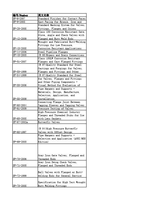
SP-42-2009
SP-43-2008 SP-442007
SP-53-1999 SP-54-1999
SP-55-2006
SP-58-2009 SP-60-2004 SP-61-2009
SP-65-2008 SP-67-2002a
英文名称 Standard Finishes for Contact Faces Spot Facing for Bronze, Iron and Standard Marking System for Valves, Fittings, Flanges and Unions Class 150 Corrosion Resistant Gate, Glove, Angle and Check Valves with Flanged and Butt Weld Ends Wrought and Fabricated Butt-Welding Fittings for Low Pressure, Corrosion Resistant Applications Steel Pipeline Flanges (R 08)Bypass and Drain Connections Class 150LW Corrosion Resistant Flanges and Cast Flanged Fittings (R 07)Quality Standard for Steel Castings and Forgings for Valves, Flanges and Fittings and Other (R 07)Quality Standard for Steel Quality Standard for Steel Castings for Valves, Flanges and Fittings and Other Piping Components Visual Method for Evaluation of Pipe Hangers and Supports Materials, Design, Manufacture, Selection, Application, and Installation Connecting Flange Joint Between Tapping Sleeves and Tapping Valves Pressure Testing of Valves High Pressure Chemical Industry Flanges and Threaded Stubs for Use with Lens Gaskets Butterfly Valves (R 04)High Pressure Butterfly Valves with Offset Design Pipe Hangers and Supports Selection and Application (ANSI/MSS Edition)
中国机读目录格式(CNMARC)
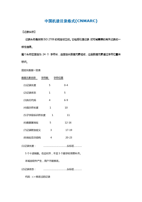
中国机读目录格式(CNMARC)【记录头标】记录头标是按照ISO 2709的规定设立的。
它包括处理记录时可能需要的有关记录的一般性信息。
整个头标区固定为24个字符长,由固定长数据元素组成,这些数据元素通过字符位置来标识。
固定长数据一览表数据元素名称字符数字符位置(1)记录长度50-4(2)记录状态15(3)执行代码46-9(4)指示符长度110(5)子字段标识符长度111(6)数据基地址512-16(7)记录附加定义317-19(8)地址目次结构420-23(1)记录长度:………………………………头标区…………5个十进制数。
右边对齐,不足5个数字时用零补齐。
本域由软件产生,用户不能修改。
(2)记录状态:………………………………头标区…………代码:c=修改过的记录d=删除的记录n=新记录o=曾为较高层次记录p=曾为不完整的预编记录(3)执行代码:………………………………头标区…………(a)记录类型,1字符代码:a=印刷的文字资料b=手稿性的文字资料(b)书目级别,1字符代码:m=单行本─专著或多卷集。
s=连续出版物─连续发行并趋向无限期连续发行的出版物。
a=分析性资料─物理上包含在另一种资料里的一种资料,它是另一种资料的组成部分。
c=汇编性著作─人为配套的著作集。
(c)层次等级代码,1字符:表示记录和其它记录有层次连接关系,说明在层次中的相对位置以及记录与同一文件中其它记录的从属关系。
代码:空格=层次关系未定0=无层次关系1=最高层记录2=低层次记录(在最高层以下的记录)(d)未定义,空格(4)指示符长度:………………………………头标区…………表示指示符长度的1位十进制数字,CN-MARC格式为2。
用户不可修改。
(5)子字段标识符长度:………………………………头标区…………表示子字段标识符长度的1位十进制数字,CN-MARC格式为2。
用户不可修改。
(6)数据基地址:………………………………头标区…………占5个字符位,用十进制数表示。
- 1、下载文档前请自行甄别文档内容的完整性,平台不提供额外的编辑、内容补充、找答案等附加服务。
- 2、"仅部分预览"的文档,不可在线预览部分如存在完整性等问题,可反馈申请退款(可完整预览的文档不适用该条件!)。
- 3、如文档侵犯您的权益,请联系客服反馈,我们会尽快为您处理(人工客服工作时间:9:00-18:30)。
FFCS (Fieldnetwork FCS) quotation guidanceAt R3.04, the new compact FCS named FFCS is released. This document is the guidance when you quote this FFCS. The pricing mechanism of FFCS and the specification of FFCS are different from those of KFCS, so please understand the characteristics of each in order to provide attractive proposal for your customers.1 ISD-MASP-S030501. FFCS Basic Configuration1.1 AppearanceI/O module slot. (8 slots) CPU modules(inc. SB bus I/F)Power Supply module5-unit(Same size as FIO node)1-unitVnet Coupler (10base2)1.2 Vnet CableDedicated cable (Attached with FFCS) (Neither RJ45 and 10BaseT)Vnet Cable Only 10Base2 is available.Coupler No T-type connector is needed separately.10Base5 cableIf you need to connect a 10Base5 cable, connect it via YCB149 or YCB147.2 ISD-MASP-S030501.3 I/O nodes Expansion.Up to 3 I/O nodes can be connected to one FFCS as expanded I/O node. When you expand I/O nodes, you need the interface module to connect ESB bus cable or ER bus cable. In case of ESB bus, the module EC401 is required. (New model name.) In case of ER bus, use EB401. (Same as KFCS) Up to 3 pairs of EB401 (= 6 modules) can be installed in one FFCS. Only one pair of EC401 (<> 2 modules) can be installed in one FFCS. The example of FFCS configuration with the expansion node by ESB bus is shown below. EC401 Only one pair (One segment)ESB bus cableLocal nodes ANB10S or ANB10D3 ISD-MASP-S030502. How to choose, KFCS or FFCS ?2.1 Comparison with the specificationTbl. 1 Main Specification ComparisonKFCS FFCS 16MB, 32MB 32MB only Single CPU or Redundant CPU Single CPU or Redundant CPU With Cabinet type or 19” Rack Mountable Type only 19” Rack Mountable Type 15 4 (Inc. CPU node) 116 30 All FIO modules of KFCS can be used also for FFCS. The HART function of FFCS is same as that of KFCS. All of the subsystem communication packages released for KFCS are available also for FFCS.CPU Repertory Cabinet Max number of I/O node Max number of I/O module I/O Legacy I/O FF PROFIBUS-DP RS, Ethernet Subsystem comm. Redundancy CPU Power Supply I/O Bus cable I/O module VnetMinimum size SI bus connection (for XL, V)Selectable Pair&Spare redundancy CPU module. Redundancy is selectable. Redundancy is selectable. Redundancy is selectable for all modules. Redundancy. (Single is not available) 14-unit (622mm) 6-unit (267mm) Available Not available.4 ISD-MASP-S03050Tbl. 2 Capacity ComparisonFFCS Tag names Process I/O Comm. I/O Internal Switches Messages Elements per FCS Function blocks Analog I/O points Contact I/O points Data volumes No. of ALR/ALE/ALP Common Switches Global Switches Annunciator Message Messages printed Operator guide Messages Request Messages Event Messages Control drawings Acquisition points 5,800 2,500 480 1,920 4,000 8 4,000 256 1,000 1,000 500 200 500 200 256 KFCS (16MB) (32MB) 2,000 5,800 2,500 2,500 1,280 1,280 4,096 4,096 4,000 4,000 6 16 4,000 4,000 256 256 500 1,000 400 1,000 200 200 200 200 256 500 200 500 200 256Control Functions Real-time trendTbl. 3 FCS Template CapacityKFCS (General-purpose) (16MB) (32MB) 10 10 16 16 700 250 450 400 10 0 450 600 200 150 150 200 0 0 0 10 0 0KB 1,200 600 600 500 60 400 1,000 700 200 200 200 400 60 40 0 250 70 1MBFFCS Node ALF111 Regulatory Control Blocks Calculation Blocks (FF-FP blocks) Sequence blocks General-purpose Calculations SFC blocks Operation Blocks Switch Instrument Sequence Element 1 Faceplate blocks Logic operation blocks Sequence Element 2 Batch data blocks Unit Instruments Offsite blocks Valve Pattern Monitors SEBOL Daemon SEBOL User Function Control Recipe 4 8 500 500 200 400 40 200 500 500 120 100 100 100 30 30 0 210 70 1MB5 ISD-MASP-S030502.2 Comparison with hardware configurationPlease assume the case of more than 30 FIO modules or the case of more than 3 remote sites. If you adopt KFCS, you use more I/O nodes. If you adopt FFCS, you use more FFCS. The following example is the extreme comparison for your reference. This is between the case of KFCS+Remote I/O and the case of FFCS. VnetCPUCPUCPUCPUControl− The control response is quicker. As it is not needed to use ER bus, the turn around time is much shorter. − You can execute offline maintenance for each control unit. (While offline downloading to one FCS, other control units are not affected.)− The total length of Vnet is 15km. To extend the length with generic devices is not available. − The environmental condition of FFCS is same as the FCU of KFCS, so the place to put FFCS is limited. − Star-type connection is not available.VnetER busCPUControl− As it is Ethernet base, you can easily extend the length of ER-bus with the generic repeater or microwave devices. − FIO nodes can be in hard environmental condition (G3, high-temperature, Zone2), − Star-type connection is available, because up to 4 segments of ER bus can be use in one FCS− The turn around time is little bit longer, because the communication with CPU through ER-bus is needed. − While offline downloading to FCU, all I/O node stop working. (Fall back)6 ISD-MASP-S030502.3 Price ComparisonAs the system price is decided case by case, it is impossible to say simply “Which is lower price, KFCS or FFCS ?”. For you reference, some examples are shown here. The charts in this page show the total transfer price (FCS, Node, I/O modules, FCS basic software) of KFCS and FFCS against the total I/O number. The transfer rate is assumed as below. This rate is closed your actual transfer rate. (The rate of FFCS is lower than that of KFCS) For simple calculation to specify the type and number of I/O modules, it is assumedAnalog : Digital = 1 : 3 Input : Output =4 : 1. No fieldbus, No TC, RTD etc.Node FFCS Software0.3 0.25 0.35(a) Single FCU, Single FIO, Non-isolated modules)Price (US$)FCSTransfer Rate 0.3500100015002000Total I/O number(b) Redundant FCU, Redundant FIO, Isolated modules)500 1000 1500 2000Price (US$)Total I/O numberThese charts can specify that less than 700-800 I/O points for single FCU, single FIO system or less than 1300 I/O points for redundant system, FFCS is cost-competitive than KFCS.7 ISD-MASP-S03050The charts in this page show the price comparison against the number of node. KFCS with local node, FFCS without expansion nodes, and FFCS with expansion nodes are compared. I/O modules are not included.Price (US$)510(a) Single FCSTotal node numberPrice (US$)(b) Redundant FCS510Total node number These charts can specify that the system with less than 6 nodes, FFCS is cost-competitive than KFCS.8 ISD-MASP-S030503. Ordering Guidance3.1 FFCS itself (CPU node)You can choose single CPU type and redundancy CPU type. No cabinet type like AFS40D is available. If you place an order the following models (AFF50S/AFF50D), it includes the backboard, power supply modules, CPU modules, Vnet couplers, and the cables between CPU modules -Vnet couplers. Vnet must be redundancy configuration. (No single configuration)Description System CSL// Order Code Model AFF50S -H 3 4 1 Suffix Codes 1 2 4 0 For CS3000 Field Control Unit (For FIO, 19" Rack Mountable) Compact Type Dual-redundant Vnet, Single Power Supply Dual-redundant Vnet, Dual-redundant Power Supply Always 1 100-120V AC Power Supply 220-240V AC Power Supply 24V DC Power Supply Always 0 1 LFS1350 Basic Software LicenseDescription System CSL// Order Code Model AFF50D -H 4 1 1 Suffix Codes 2 4 0 For CS3000 Field Control Unit (For FIO, 19" Rack Mountable) Compact Type Dual-redundant Vnet, Dual-redundant Power Supply Always 1 100-120V AC Power Supply 220-240V AC Power Supply 24V DC Power Supply Always 0 1 LFS1350 Basic Software LicenseUp to 8 I/O modules (include EC401, EB401) can be in one AFF50S or one AFF50D.9 ISD-MASP-S030503.2 Node ExpansionWhen using ESB bus, you need to order EC401 module for the FFCS CPU node. Only one pair of EC401 can be installed in one FFCS CPU node. When using ER bus, it is same as the case of KFCS that you need to order EB401 module. Up to 3 pairs of EB401 can be installed in one FFCS. About node itself, please order it separately as ANB10S, ANB10D, or ANR10S, ANR10D. In case of KFCS, you need to order only the node hardware. However in case of FFCS, only hardware ordering is not enough. (Caution !) You need to quote the software license for expansion node as the option code of node hardware.EC401 Only one pair is available for one FCS. If you do not use expansion nodes, EC401 is not needed. ESB bus cable (YCB301) Local node (ANB10S, ANB10D) Common hardware with KFCS. But in case of FFCS, you must not forget to order (quote) the software license of expansion nodes as the option code of node hardware. This is necessary for each expansion node of FFCS:Description System CSL// Order Code Model EC401 -1 Suffix Codes 0 For CS3000 ESB Bus Coupler Module Standard Type Always 0Description System CSL// Order Code Model ANB10D -4 1 Suffix Codes 2 4 0 1 /CU2N Option Codes /CU2T /ATDOC /NDEL For CENTUM CS 3000 Node Unit for Dual-Redundant ESB Bus (19-inch Rack M ountable) Dual-redundant power supply (Note 1) 100 - 120 V AC power supply (conforms to Safety Standards CSA1010) 220 - 240 V AC power supply (with CE M ARK and C-Tick M ARK) 24 V DC power supply (with CE M ARK and C-Tick M ARK) Basic type With ISA Standard G3 option Connector Unit for ESB Bus [Part No.: S9879UK (2 pieces)] Connector Unit with Terminator for ESB Bus [Part No.: S9880UK (2 pieces)] Explosion Protection M anual FFCS Node LicenseCaution !10 ISD-MASP-S030503.3 Entry Pack (Special discount package of FFCS software)Please order LHS1100 as FFCS operation and monitoring function. Of course please order LHS5100 as the builder function. These are common with KFCS, LFCS, and PFCS. If the following conditions are satisfied, you can adopt the “Entry Pack” for attractive price. - New project - Only FFCSs are used. (No KFCS, LFCS, PFCS)1 - The number of FFCS is less than 4. Select the Basic license for the 1st HIS, and select the multiple-license for the other HISs.Description System CSL// Order Code Model LHSBEPK -S 0 Suffix Codes 1 /N0001 /N0003 For CS3000SP (US$)Option CodesCS3000 Software Basic Entry Pack Basic Software License Standard Operation and Monitoring Function Standard Operation and Monitoring Function with builder function(LHS5100) and graphic builder (LHS5150) 1 English version Total of control station is 1 station Total of control station is 3 station70-80% of LHS1100 Approx. 50% of LHS1100+LHS5100+LHS5150Description System CSL// Order Code Model LHSBEPK -C 0 Suffix Codes 2 /N0001 /N0003 For CS3000SP (US$)Option CodesCS3000 Software Basic Entry Pack Multiple Software License Standard Operation and Monitoring Function Standard Operation and Monitoring Function with builder function(LHS5100) and graphic builder (LHS5150) 1 English version Total of control station is 1 station Total of control station is 3 station70-80% of LHS1100 Approx. 50% of LHS1100+LHS5100+LHS51501Rev 1 : The policy was changed.(Oct. 21, ’03) 11 ISD-MASP-S030503.4 Ordering Item Example (Ex.1)HIS-1 HIS-2 HIS-3 HIS-43 sets of remote nodes. 2 sets of local nodes.Tbl. 4 FFCS related H/W and S/WModel Code AFF50D-H41201 ANB10D-420/CU2N/NDEL ANB10D-420/CU2T/NDEL ANR10D-420/NDEL YCB301-C100 EC401-10 EB401 YCB141-M100 LHS1100-S11/N0004 LHS1100-C11/N0004 LHS5100-S11/N0004 LHS5150-S11 Description FFCS CPU node Local node Local node Remote node ESB bus cable ESB bus coupler module ER bus master module ER bus cable Basic license of operation/monitoring Multiple license of operation/monitoring Standard builder Graphic builder Qty 3 1 1 3 4 2 4 6 1 3 1 1 For HIS-1 For HIS-2,3,4 For HIS-1 For HIS-1 Without terminator With terminator Memo12 ISD-MASP-S03050(Ex. 2)HIS-1 HIS-2 HIS-3 HIS-43 sets of local nodes.3 sets of local nodes.Tbl. 5 FFCS related H/W and S/WModel Code AFF50D-H41201 ANB10D-420/CU2N/NDEL ANB10D-420/CU2T/NDEL YCB301-C100 EC401-10 LHSBEPK-S11/N0003 LHSBEPK-C01/N0003 Description FFCS CPU node Local node Local node ESB bus cable ESB bus coupler module Entry Pack with builder Entry Pack without builder Qty 3 4 2 12 4 1 3 For HIS-1 For HIS-2,3,4 Without terminator With terminator Memo13 ISD-MASP-S03050。