NiosII_SOPCBuilder_Labs
SOPCNIOSII开发流程(精)
SOPC/NIOS II 開發流程
硬體開發流程
Quartus II
New Project (.qpf)
SOPC Builder
Add Processor
Add Controllers Component Connect Code Generate (.v) Top Design (.v) Pin Assignment (.qsf) Compile (.sof)
元件 以Address 來 定址所要 Access 的元件
10
SOPC/NIOSII 設計與實作課程
© 2007 Terasic Corporation
SOPC Example
11
SOPC/NIOSII 設計與實作課程
© 2007 Terasic Corporation
SOPC Builder 輸出
– HDL Source File – 硬體描述檔(.PTF)
7
SOPC/NIOSII 設計與實作課程
© 2007 Terasic Corporation
SOPC Builder 介面
元件區
系統建構區
8
SOPC/NIOSII 設計與實作課程
© 2007 Terasic Corporation
SOPC 建構流程
3
SOPC/NIOSII 設計與實作課程
© 2007 Terasic Corporation
NIOS II 版本
• 版本
• 軟體相容性
– Binary Code Compatible (No changes required when CPU version is changed.)
Nios II_SOPC开发

2010-12-22
1
5.3.1 Nios II的硬件开发 的硬件开发 Nios II是一个用户可以自行定制的 是一个用户可以自行定制的CPU,用户可以增加新 是一个用户可以自行定制的 , 的外设,增加新的指令,分配外设的地址等。 的外设,增加新的指令,分配外设的地址等。Nios II的硬件开 的硬件开 发就是由用户定制合适的CPU和外设。SOPC Builder提供了 和外设。 发就是由用户定制合适的 和外设 提供了 大量的IP 来加快Nios II外设的开发速度,用户也可以使 外设的开发速度, 大量的 Core来加快 来加快 外设的开发速度 来定制外设。 用VHDL或Verilog HDL来定制外设。 或 来定制外设 Nios II的硬件开发必须得到特定的开发板的硬件支持。下 的硬件开发必须得到特定的开发板的硬件支持。 的硬件开发必须得到特定的开发板的硬件支持 面以DE2(含DE2 70)开发板为例,介绍 版本) 面以 ( )开发板为例,介绍Nios II(9.0版本) ( 版本 硬件开发的具体流程。 硬件开发的具体流程。 开发板上, 在DE2开发板上,支持 开发板上 支持Nios II系统的外部设备包括 系统的外部设备包括 SDRAM、SRAM、FLASH、LCD、七段数码管、发光二极管、 、 、 、 、七段数码管、发光二极管、 按钮开关、电平开关、 器件等, 按钮开关、电平开关、VGA、ISP1362、I2C器件等,大部分 、 、 器件等 外部都采用Nios II软件提供的组件,但SRAM、七段数码管、 软件提供的组件, 外部都采用 软件提供的组件 、七段数码管、 VGA控制器和 控制器和I2C器件属于 器件属于DE2开发板自定义的组件,因此在 开发板自定义的组件, 控制器和 器件属于 开发板自定义的组件 进行Nios II系统开发之前,应将这些组件的程序包加入到 系统开发之前, 进行 系统开发之前 应将这些组件的程序包加入到Nios 2010-12-22 2 II的用户自定义组件(User Logic)中。 的用户自定义组件( 的用户自定义组件 )
NOIS II嵌入式处理器

NIOS嵌入式处理器Nios嵌入式处理器于2001年首次推出,创新的Nios® 嵌入式处理器成为业界第一款专门针对FPGA的商用处理器。
自此以后,众多的FPGA用户采用了Altera 提供的Nios和Nios II处理器。
Altera建议新设计采用Nios II处理器。
在二○世纪九十年度末,可编程逻辑器件(PLD)的复杂度已经能够在单个可编程器件内实现整个系统。
完整的单芯片系统(SOC)概念是指在一个芯片中实现用户定义的系统,它通常暗指包括片内存储器和外设的微处理器。
最初宣称真正的SOC――或可编程单芯片系统(SOPC)――能够提供基于PLD的处理器。
在2000年,Altera发布了Nios处理器,这是Altera Excalibur嵌入处理器计划中第一个产品,它成为业界第一款为可编程逻辑优化的可配置处理器。
本文阐述开发Nios处理器设计环境的过程和涉及的决策,以及它如何演化为一种SOPC工具。
Altera很清楚地意识到,如果我们把可编程逻辑的固有的优势集成到嵌入处理器的开发流程中,我们就会拥有非常成功的产品。
基于PLD的处理器恰恰具有应用所需的特性。
一旦定义了处理器之后,设计者就“具备”了体系结构,可放心使用。
因为PLD和嵌入处理器随即就生效了,可以马上开始设计软件原型。
CPU周边的专用硬件逻辑可以慢慢地集成进去,在每个阶段软件都能够进行测试,解决遇到的问题。
另外,软件组可以对结构方面提出一些建议,改善代码效率和/或处理器性能,这些软件/硬件权衡可以在硬件设计过程中间完成。
Nios II系列软核处理器是Altera的第二代FPGA嵌入式处理器,其性能超过200DMIPS,在Altera FPGA中实现仅需35美分。
Altera的Stratix 、Stratix GX、 Stratix II和 Cyclone系列FPGA全面支持Nios II处理器,以后推出的FPGA器件也将支持Nios II。
NIOSII SOPC实例1

一.关于SOPC1)SOPC英文全名为:System-On-a-Programmable-Chip,即可编程片上系统。
SOPC 用可编程逻辑技术把整个系统放到一块硅片上,来用于嵌入式系统研究和电子信息处理。
SOPC是一种特殊的嵌入式系统,它是片上系统(System-On-a -Chip,SOC),即由单个芯片完成整个系统的主要逻辑功能但它不是简单的SOC,它也是可编程系统,具有灵活的设计方式,可裁减、可扩充、可升级,并具备软硬件在系统可编程的功能。
SOPC设计包括以32位NIOSII软核处理器为核心的嵌入式系统的硬件配置、硬件设计、硬件仿真、软件设计以及软件调试等。
SOPC系统设计的基本软件工具有:1)QuartusII:用于完成NIOSII系统的综合、硬件优化、适配、编程下载以及硬件系统调试等;2)SOPC Builder:Altera NiosII嵌入式处理器开发软件包,用于实现NiosII 系统的配置、生成,内嵌于QuartusII软件中;3)ModelSim: 用于对SOPC生成的NiosII系统的HDL描述进行系统的功能仿真;4)NiosII IDE:用于进行软件的开发、调试,以及向目标开发板进行Flash下载;二.关于NIOSII处理器NIOSII 是一个可配置的软核处理器。
“可配置”的意思是设计者可以根据性能和成本的要求来增加或删减处理器的功能。
ALTERA公司并不销售NIOSII处理器芯片,而是销售空的FPGA,并提供NIOSII 系统相应的IP核来组成NIOSII系统,然后将这个系统下载到FPGA中实现。
1)关于AVALONAvalon总线是SOPC硬件系统的重要组成部分,Avalon总线规范是为了开发SOPC 环境下外设而设计的。
图1-1 一个SOPC的示例二. SOPC简单实例:软核控制LCD液晶字母显示器1.系统构成规划1)系统功能:在character LCD上显示”Hello LCD from NiosII!”2)本系统中需要的外围器件:(1)L CD:输出显示(2)S RAM存储器:程序运行时将其导入SRAM3)SOPC中建立系统需要添加的模块包括:(1)N ios II 32bit CPU(2)L CD display(3)外部RAM总线(4)外部RAM接口(5)J TAG UART Interface(6)定时器2.硬件系统的建立1)首先打开Quartus II 建立工程文件:将工程文件命名为hello_lcd,顶层文件与工程文件同名。
NIOSII实验手册V1

NIOSII程序设计--FPGA开发板配套教程(二)广西师范大学目录第二节 SOPC概述 (1)2.1NIOSII开发流程 (1)2.2NIOSII IDE功能说明 (2)2.3软件版本与开发平台 (4)第三节 NIOSII程序设计 (5)实验一点亮LED灯 (5)实验二NIOSII系统设计 (36)实验三PIO外部中断-接键开关 (46)实验四数码管显示驱动 (56)实验五T IMER定时器 (59)实验六串口通信实验 (69)实验七LCD显示操作 (78)第二节 SOPC概述SOPC是system on a programmable chip的缩写,顾名思义就是把一个系统集成在单片可编程芯片中。
一个最小系统应该包括中央处理单元(CPU)、随机存储器(RAM)和Flash ROM(存储代码、数据等),稍微复杂点的系统至少应该包括UART、DMA、Timer、中断管理模块以及GPIO等。
早在2002年的时候,Altera公司就基于SOC的设计思想,推出了其第一款32位RISC CPU软核——Nios,那时的Nios CPU功能简单,执行效率低下且不支持在线调试,所以并未得到很大的推广。
在Nios CPU基础上,Altera公司又于2005年推出了其第二代32位RISC CPU——Nios II。
与Nios CPU相比,Nios II CPU在性能方面得到了质的提升,指令执行速度快,执行效率高,且支持JTAG在线调试。
2.1NIOSII开发流程Nios II CPU的开发流程与Nios CPU基本一致,唯一不同的就是Nios CPU的软件开发是在Nios SDK Shell下进行,而Nios II CPU则是在Nios II IDE集成环境下开发。
其基本开发流程依旧为:(1)在Quartus II中新建一个工程(硬件)。
(2)在SOPC Builder中根据自己的需要加入各种IP核。
(3)利用SOPC Builder产生Quartus II能够识别的文件。
nios ii固化程序到sopc的实现
Nios II下载程序到串行配置芯片EPCS方法:1 在SOPC Builder内添加epcs_controller模块,将cpu的reset地址设置在epcs_controller 上2 重新编译Quartus3 在Nios II IDE里将system library的Program memory(.text)和Read_only data memory(.rodata)设置为onchip_mem或者sdram,编译。
4 下载sof文件到板子5 进入Nios II IDE,在Tool菜单下选择FLASH Programmer,选择要下载的工程和与工程配套的.sof文件一起下载到EPCS中,注意一定要同时选择两个一起下载,hardware image选择custom即可,memory选择epcs controller。
系统会自动分配地址。
如果不选择同时下载配置文件,会出现提示。
Nios II下载程序到CFI FLASH,配置文件到串行配置芯片EPCS的方法:1 在SOPC Builder内添加CFI_FLASH模块,将cpu的reset地址设置在CFI_FLASH上2 重新编译Quartus3 在Nios II IDE里将system library的Program memory(.text)和Read_only data memory(.rodata)设置为onchip_mem或者sdram,编译。
4 下载sof文件到板子5 进入Nios II IDE,在Tool菜单下选择FLASH Programmer,选择要下载的工程到CFI FLASH 里,配置程序下载到EPCS中(也可以不加epcs_controller模块,通过POF方式固化配置程序)不用AS接口,用JTAG口配置EPCS器件,具体步骤如下:1 在Quartus中打开工程,编译生成配置文件.sof2 选择File->Convert Programming Files,调出Convert Programming Files对话框3 Ouput programming file 对话框内,Programming file type选择JTAG Indirect Configuration File(.jic);4 Configuration device 选择使用的配置芯片,如EPCS165 File name填写输出文件名称,如output_file.jic6 Input files to convert 对话框内,选中Flash Loader,点击Add Device按钮,在弹出对话框中选择你的FPGA芯片7 选中SOF DATA,点击Add file按钮,在弹出的资源浏览器中找到并选中.sof文件,打开它8 点击generate按钮生成output_file.jic9 打开Quartus的Programmer对话框,选择JTAG模式10 点击add file按钮,选择output_file.jic文件,并将Program复选框上打勾11 确定好JTAG电缆后,点击start,Quartus会先配置FPGA,然后再对FPGA烧写配置芯片。
niosII_笔记
这几天开始研究niosII,把学习的过程记下来吧,给论坛的各位同胞们。
本例过程跟网上其它的基本差不多,只不过软件是用的6.1的。
另外有些问题也归纳一下,给论坛的同志们。
一、EDA软件的安装1.安装QuartusII2.安装niosII说明:本示例采用6.1版本软件,其它版本界面稍有不同。
(安装过程非本文说明重点)板子是用烟鱼那款EP1C3T14。
二、建立niosII系统1. 建立项目。
建立一个目录,比如F:\test启动QuartusII6.1软件选择File->New Project Wizard做nios系统的时候最好先选好器件,以免引起不必要的麻烦。
2. 如何生成一个可调试的nios 最小系统:选择 Tools -> SopcBuilder,启动Altera SOPC Builder启动Altera SOPC Builder后,SOPC Builder会立刻弹出对话框填入System Name,比如niosII_e;HDL Language ,比如选择verilog,如下图:点OK。
Board Target ,比如,我选择Unspecified Board; Target Device Family,我选择Cyclone(用的是EP1C3T144)Clock我用的是50M Hz. 如下图:添加niosII处理器到系统中。
注意:论坛里有些人提到在装完niosii后看不到NiosII Processor。
我今天也遇到过这样的问题,莫名其妙(以前没有遇到过)。
解决的办法就是打开SOPC Builder系统界面后,在File->SOPC Builder Setup中的Component/Kit Library Search Path中添加相应的路径(比如我的如下图(装在C盘下)),然后退出QuartusII(包括SOPC Builder) ,重启即OK。
双击 Nios II Processor -Altera Corporation,会弹出Altera niosII 对话框,在NiosII core配置选项中,点击Nios II/e区域,选择Nios II/e,如下图。
SOPC_Nios II体系结构

❖ Nios II把外部硬件 的中断事件交由中 断控制器管理,内 核异常事件交由异 常控制器管理。
clock
NiosII处理器核
reset
cpu_resetrequest cpu_resettaken
地址发生器 &
软件调
程序控制器
试接口
JTAG接口
异常控制器
中断源 [0..31]
中断控制器
通用寄存器组 r0..r31
• 0表示处于超级用户态
ct15
(Scuppueidrvisor Mode)。 唯一的CPU序第列0号位PIE—外设中断允许位:
• 1表示允许外设中断;
• 0表示禁止外设中断。
寄存器 ct10 ct11 ct12 ct13 ct14 ct15
控制寄存器一览
控制寄存器组
名字
bit位意义: 31…2
1
5.1.1 Nios II处理器结构
clock
NiosII 处理器核
reset
cpu _resetrequest cpu _resettaken
地址发生器 &
软件调
程序控制器
试接口
JTAG 接口
异常控制器
中断源 [0 ..31]
中断控制器
通用寄存器组 r0..r31
控制寄存器组 ctl0..ctl5
0
status
保留
U PIE
estatus
保留
EU EPIE
bstatus
保留
BU BPIE
ienable
中断允许位
estatus、bstatus—都是status寄存器的影子寄存器:
ipending •发生断点或者异中常断时发:生保标存志sta位tus寄存器的值;
NIOSII教程

NIOSII教程1.NIOSII概述:介绍NIOSII的特点、应用领域和产品系列。
2.NIOSII架构和指令集:介绍NIOSII的架构和指令集。
NIOSII的架构包括处理器核、存储器和外设接口等。
处理器核由五个主要部分组成:指令译码器、执行单元、数据通路、存储器接口和外设接口。
NIOSII的指令集包括常见的RISC指令,如加载、存储、算术逻辑和分支等。
3.NIOSII的软件开发环境:介绍NIOSII的软件开发环境和相关工具。
4.NIOSII的软件编程:介绍NIOSII的软件编程方法和技术。
在NIOSII上进行软件编程可以使用C语言和汇编语言。
用户可以使用开发工具来编写、调试和运行自己的软件。
此外,NIOSII还支持外设驱动程序的编写和集成,以实现与外部设备的交互。
5.NIOSII硬件设计:介绍如何进行NIOSII的硬件设计和集成。
6.NIOSII的调试和性能优化:介绍如何进行NIOSII的调试和性能优化。
在NIOSII的开发过程中,调试和性能优化是非常重要的环节。
用户可以使用调试器来调试和分析程序的执行过程,以发现和修复错误。
此外,用户还可以通过改进代码结构和算法来提高程序的性能。
7.NIOSII的应用案例:介绍一些NIOSII在实际应用中的案例。
总结:NIOSII教程主要介绍了NIOSII的概述、架构、指令集、软件开发环境、软件编程、硬件设计、调试优化和应用案例等内容。
通过学习NIOSII教程,用户可以获得关于NIOSII的全面知识,并能够利用NIOSII 进行快速设计和开发嵌入式系统。
nios2+c语言编程方法Nios2系列教程
nios2+c语言编程方法Nios2系列教程最小的Nios2系统前言2003年Altera推出了第一代32位Nios系统,开创了FPGA内构建高性能单片机的先河。
随之2004年,Nios系统升级为Nios2系统,解决了软硬件开发中一些不方便的问题,软件开发环境从命令行编译转移到Eclips的IDE集成开放环境。
Nios2开发环境从1.0、1.1到 1.2逐步升级。
后来为了和QuartusII软件升级同步,从QuartusII5.0版本开始Nios2的版本号正式和QuartusII统一。
作者我亲身经历过整个Nios2发展历程,深知Nios2的不同版本发生的巨大变化。
目前网上流行的Nios2教程针对的版本相对较老,已经对初学者学习Nios2起不到指导作用,并且应广大爱好者的强烈要求,我在此使用QuartusII和Nios2的8.0版本详细叙述Nios2的开发流程。
构建一个Nios2最小系统需要什么构建一个Nios2最小系统需要具备以下资源:★Nios2软核处理器★内存★Jtag_uart调试接口1. Nios2软核处理器:这就是Nios2处理器的核心CPU,所有的外设都是和这个CPU通过Avalon总线连接到一起的。
2. 内存:编译后的程序代码需要通过下载线下载到该内存中,然后CPU的程序指针跳转到内存的首地址开始执行程序。
3. Jtag_uart调试接口:想要用单步调试等调试功能控制程序执行和查看程序变量,那么就需要这个调试接口。
开始构建一个再简单不过的Nios2工程整个步骤由2部分组成,第一部分建立Nios2硬件SOPC工程,第二部分建立Nios2软件工程。
1.建立Nios2硬件SOPC工程建立Nios2硬件SOPC工程就是设计一个软核CPU和它的外设,编译成硬件电路放到FPGA芯片里面。
这时候可以认为FPGA就是一个32位的单片机了,下面的软件开发都是针对这个单片机的。
打开QuartusII软件,新建一个工程选择EP2C8Q208C8芯片。
一种基于NiosII的可重构DSP系统设计,SOPC,Nio(精)

一种基于NiosII的可重构DSP系统设计,SOPC,NiosII嵌入式软核处理器,FPGA,DSP引言为了解决传统DSP所面临的速度低、硬件结构不可重构、开发升级周期长和不可移植等问题,本文应用Altera公司推出的NiosIl嵌入式软核处理器,提出了一种具有常规DSP的NiosII系统功能SOPC解决方案。
由于可编程的NiosII核含有许多可配置的接口模块,用户可根据设计要求,利用QuartusII 和SOPCBuilder对NiosII及其外围系统进行构建。
用户还可通过Matlab和DSPBuilder,或直接用VHDL等硬件描述语言,为NiosII嵌入式处理器设计各类硬件模引言为了解决传统DSP所面临的速度低、硬件结构不可重构、开发升级周期长和不可移植等问题,本文应用Altera公司推出的NiosIl嵌入式软核处理器,提出了一种具有常规DSP的NiosII系统功能SOPC解决方案。
由于可编程的NiosII 核含有许多可配置的接口模块,用户可根据设计要求,利用QuartusII和SOPC Builder对NiosII及其外围系统进行构建。
用户还可通过Matlab和DSP Builder,或直接用VHDL等硬件描述语言,为NiosII嵌入式处理器设计各类硬件模块,并以指令的形式加入到NiosII的指令系统中,使其成为NiosII 系统的一个接口设备,与整个片内嵌入式系统融为一体,而不是直接下载到FPGA中生成庞大的硬件系统。
正是NiosII所具有的这些重要特点,使得可重构单片DSP系统的设计成为可能。
Nios II嵌入式系统设计流程NiosII嵌入式处理器专为单芯片可编程系统设计而优化,是一种面向用户、可以灵活定制的通用RISC(精简指令集)嵌入式CPU。
它采用Avalon总线结构通信接口,带有增强的内存、调试和软件功能,可采用汇编或C、C++等进行程序优化开发。
NiosII具有32位指令集、32位数据通道和可配置的指令及数据缓冲。
建立NIOSII处理器系统基本流程
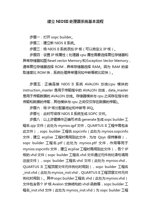
建立NIOSII处理器系统基本流程步骤一:打开sopc builder。
步骤二:建立新NIOS II系统。
步骤三:给NIOS II系统添加IP核(可以自定义IP核)。
步骤四:设置IP核属性(处理器cpu属性需要选择复位存储器和异常存储器如图Reset vector Memory和Exception Vector Memory,通常复位存储器选择ROM,异常存储器选择RAM。
因为RAM的读取速度比ROM快,系统处理异常情况如中断等就比较快)。
步骤五:正确连接NIOS II系统AVALON总线(cpu模块的instruction_master是用于传输指令的AVALON总线,data_master 是用于传输数据的AVALON总线。
存储器模块与cpu之间存在指令的传输和数据的传输,其他模块与cpu之间仅仅存在数据的传输)。
步骤六:给IP核分配基地址和中断号IRQ。
步骤七:此时可保存NIOS II系统生成.SOPC文件。
步骤八:以上步骤操作正确可点击generate生成sopc builder工程名.qip文件(此处为mynios.qpf文件,QUARTUS II工程中需包含此文件),sopc builder工程名.sopcinfo(此处为mynios.sopcinfo 文件,建立ecplise工程时需用到此文件,为与Qsys保持兼容),sopc builder 工程名.ptf(此处为mynios.ptf文件,作用等同于mynios.sopcinfo文件,建立ecplise工程时需用到此文件),各个IP 核的.vhd文件(sopc builder工程名.vhd文件通过元件例化语句调用这些文件),sopc builder工程名.vhd文件(此处为mynios.vhd,QUARTUS II工程顶层文件元件例化时用到),sopc builder工程名_inst.vhd(此处为mynios_inst.vhd,QUARTUS II工程顶层文件元件例化时用到)。
NiosII外围设备--SOPC技术与应用
5.2 SDRAM控制器内核
ACTIVE到READ或WRITE延时允许值:-默认值:20ns 描述:ACTIVE到READ或WRITE延时。
5.2 SDRAM控制器内核
访问时间(t_ac)允许值:-默认值:5.5ns 描述:时钟边沿的访问时间。该值由CAS的等待时间决定。
5.2 SDRAM控制器内核
5.1 并行输入/输出内核
PIO内核简介
最多32个I/O端口
寄存器
Nios II 系统
Pio[31]Pio[30]Pio[29]Pio[3]Pio[2]Pio[1]Pio[0]
Pio[7]Pio[6]Pio[5]Pio[5]Pio[3]Pio[2]Pio[1]Pio[0]
端口数可设置
每个Avalon接口的PIO内核可提供32个I/O端口且端口数可设置,用户可以添加一个或多个PIO内核。CPU通过I/O寄存器控制I/O端口的行为。I/O口可以配置为输入、输出和三态,还可以用来检测电平事件和边沿事件。
在初始化前、上电后延时允许值:-默认值:100us 描述:从稳定的时钟和电源到SDRAM初始化的延时。
5.2 SDRAM控制器内核
刷新命令(t_rfc)的持续时间允许值:-默认值:70ns 描述:自动刷新周期。
5.2 SDRAM控制器内核
预充电命令(t_rp)的持续时间允许值:-默认值:20ns 描述:预充电命令周期。
5.2 SDRAM控制器内核
每隔一段时间执行一个刷新命令允许值:-默认值:15.625us 描述:该值指定SDRAM控制器多久刷新一次SDRAM。典型的SDRAM每65ms需要5,096刷新命令,通过每65ms/5,096=15.625us执行一个刷新命令来符合这个要求。
【FPGA黑金开发板】NIOSII那些事儿--硬件开发(一)
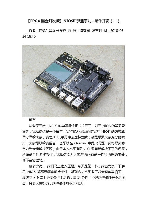
【FPGA黑金开发板】NIOSII那些事儿--硬件开发(一)作者:FPGA黑金开发板来源:博客园发布时间:2010-03-24 18:45前言从今天开始,NIOS的学习征途正式拉开了。
对于NIOS的学习爱好者,我相信这是一个福音,我将毫无保留的将我对NIOS的研究成果分享给大家。
我之所以采用博客这种方式,就是想跟大家充分的交流,大家可以给我留言,也可以在Ourdev中提出问题,我将尽我的全力为大家解决问题。
由于本人水平有限,如果有我解决不了的问题,还请高手们多多帮忙,我相信能为大家解决问题是一件很快乐的事情,你不会错过的。
废话少说,我们马上进入正题。
今天是第一节,我首先说一下学习NIOS都需要哪些前提条件。
听到这,初学者可以会有些害怕了,难道学习NIOS还要条件?是的,需要条件,不过这些条件并不是很高,只要大家努力,这些条件都不是问题。
•具有一定的单片机基础;•具有一定的C语言编程能力;•了解 Quartus II的开发流程;•一块开发板;就这么多,大家觉得难么?首先说说第一条,具有一定的单片机基础,这个条件是要有的。
单片机的基础在NIOS II学习中体现在它的寄存器操作方式上,这种操作方式是通用的,不管是ARM,DSP,还是51都是一样的,你只要有一种单片机的实践经验就没问题了。
再说第二条,这一条没什么可争议的,NIOS的开发完全是用C语言的,如果你没有C语言的基础,我建议你还是先学习一下C语言再考虑学习NIOS吧。
第三条呢,有最好,如果没有的话也可以,我在以后的文章中都会涉及到,大家跟着学就可以了。
第四条也不是必须的,不过学习NIOS不像学习Verilog/VHDL,通过仿真看看也行,NIOS的学习跟单片机很相似,最好是亲手操作硬件,这样对你的学习有更好的效率和效果。
在这里推荐一下我的FPGA黑金开发板,不仅仅是广告哦,因为我以后的讲解都是以我的黑金板为基础的,大家学习起来也很方便的。
简介NIOS是一个用户可配置的通用32位RISC嵌入式处理器,它是SOPC(System On a Programmable Chip,片上可编程系统)的核心。
SOPC_Builder开发工具

§4.3 SOPC Builder的用户界面
三、系统生成页
§4.3 SOPC Builder的用户界面
四、 HDL选项
当用户选择HDL选项,SOPC Builder能用HDL语 言生成系统级的硬件描述语言文件,包括:
(1)系统中每个元件的实例;
(2)元件之间相互连接的总线逻辑:包括地址译码 器,数据总线复用器,对共享资源的仲裁器,复位生 成和条件逻辑,中断优先权逻辑,动态总线宽度,主、 从设备接口的连接; (3)仿真测试,包括验证系统模块,用默认的驱动 时钟和复位输入,对外部元件的验证和连接。
§4.3 SOPC Builder的用户界面
§4.3 SOPC Builder的用户界面
二、系统设置页
设置一些附加参数,如用户可以定义程序存储器,数据存 储器,reset(复位)address,exception (异常)address,设置是 否支持SDK模式(第一代Nios的软件开发模式)。
§4.5 Avalon总线简介
AMBA总线 :
AMBA总线规范目前主要应用于ARM处理器 的内部连接。AMBA规范定义了三种总线: (1)AHB(Advanced High-performance Bus):用于连接高性能系统模块。它支持突 发数据传输方式及单个数据传输方式,所有时 序参考同一个时钟沿; (2)ASB(Advanced System Bus):用于连接 高性能系统模块,它支持突发数据传输模式; (3)APB(Advance Peripheral Bus):是一个 简单接口支持低性能的外围接口。
§4.1 Nios II软核处理器介绍
2000年,ALTERA发布了Nios处理器,它是基 于RISC技术的通用嵌入式处理器芯片软内核,特别 为可编程逻辑进行了优化设计。第一代 Nios 嵌入式 处理器性能达到50 MIPS, 采用16位指令集, 16/32位 数据通道,5级流水线技术。 2004年, ALTERA发布了Nios II嵌入式处理器,在 Cyclone II器件上可以达到100 DMIPS,在Stratix II 上可以达到超过200 DMIPS,与第一代Nios相比,最 大处理性能提高3倍,面积最大可缩小1/2。
NIOSII常见问题

首先需要声明一点,下面局部问题来自网络,如果问题,请与时通知,我将会将其删除在此提几点要求和规定:1.此贴是NIOS II FAQ,所以不收录其他相关内容;2.大家通过回帖方式进展提问,如果有其他人可以解决,也是通过回帖方式进展解决;3.问题解决以后,我会将其编入这个贴内,然后将问题跟帖删除,防止跟帖过多的影响。
4.禁止在回帖中涉与与NIOS II无关内容,一经发现立即删除。
------------------------------------------- 华丽的分割线----------------------------------------------------------------------1.NIOS能做浮点运算么?答:NIOS可以进展浮点运算,完全可以替代MCU,时钟可以跑到 100Mhz,比ARM7还要快,ARM7时钟一般为72Mhz左右。
2.NIOS是否可以不使用SDRAM和并行 FLASH?答:首先说明一下,SDRAM是用来运行程序的,FLASH是用来存储程序代码的〔SDRAM掉电丢失,FLASH如此不会〕,每次上电的时候,都需要将FLASH中的程序代码放到SDRAM中,然后再运行。
FPGA内部的memory〔onchip memory〕比拟小,跑比拟大的程序就很难了,所以我们外扩了SDRAM,以便比拟大的程序运行。
当然,我们也可以将并行的FLASH换成串行的 FLASH,而且这样可以节省很多引脚。
其实EPCS1(4,16...)就是串行FLASH,所以我们可以利用它来存储代码,至于如何设置,我后面通过博客形式来给大家讲解。
3.我的Quartus II编译硬件时没有错误,但是在下载程序的时候去出现以下错误的信息? Info: Started Programmer operation at Thu May 06 01:39:46 2010 Error: Application Nios2 on 127.0.0.1 is using the target device Error: Operation failedInfo: Ended Programmer operation at Thu May 06 01:39:46 2010 不明白这是什么意思,时好时坏?答:这种情况出现在JTAG模式下,你在使用NIOS下的JTAG功能〔比如利用BLASTER进展在线仿真〕,同时你又想下载*.sof文件〔就是在JTAG模式下下载程序〕。
- 1、下载文档前请自行甄别文档内容的完整性,平台不提供额外的编辑、内容补充、找答案等附加服务。
- 2、"仅部分预览"的文档,不可在线预览部分如存在完整性等问题,可反馈申请退款(可完整预览的文档不适用该条件!)。
- 3、如文档侵犯您的权益,请联系客服反馈,我们会尽快为您处理(人工客服工作时间:9:00-18:30)。
Designing with the Nios II Processor and SOPC Builder Exercise ManualSoftware and Hardware Requirements to Complete All ExercisesSoftware Requirements:Quartus II 7.1 ModelSim 6.1g Nios II 7.1 Altera Megacores IP 7.1Exercise ManualDesigning with the Nios II Processor and SOPC Builder2Copyright © 2007 Altera Corporation A-MNL-NIIHW-EX-7-1-v1Exercise ManualDesigning with the Nios II Processor and SOPC BuilderLab 1 Creating a Nios II Processor System3Copyright © 2007 Altera Corporation A-MNL-NIIHW-EX-7-1-v1Exercise ManualDesigning with the Nios II Processor and SOPC Builder4Copyright © 2007 Altera Corporation A-MNL-NIIHW-EX-7-1-v1Exercise ManualDesigning with the Nios II Processor and SOPC Builder1. Unless the following step has already been done for you, create a sub-directory path called “altera_trn\NiosII” on the C-drive of your computer. Copy the self-extracting zip file, “NIIHW_Class.exe” into that directory from the CD Rom provided in the class packet. 2. Then double click on NIIHW_Class.exe, and select unzip. This will create all the lab files you will need to get started inside a directory called NIIHW_class. Herein, you will find several sub-directories for each of the different types of development boards supported for this class. Inside each respective project folder is a sub-directory called niosII_lab that contains the partially completed Quartus II project that you will use as your starting point today.5Copyright © 2007 Altera Corporation A-MNL-NIIHW-EX-7-1-v1Exercise ManualDesigning with the Nios II Processor and SOPC Builder3. Navigate into the appropriate project folder for your particular development kit: (Refer to the illustrated directory structure below for help or consult instructor.) You will have to check the part on your board to confirm this. Also, please note whether your part ends with ES or not.DSP Kits FolderNios Kits FoldersEP2S60ES FolderLab Directory Structure and Working Areafor Stratix II 2S60ES kit Nios II Processor Development Kit6Copyright © 2007 Altera Corporation A-MNL-NIIHW-EX-7-1-v1Exercise ManualDesigning with the Nios II Processor and SOPC Builder4. Change directory into nios_II_lab located inside your particular kit’s project folder. Start the Quartus II Software by double-clicking on the project file located therein: (ie. niosII_lab.qpf)5. Assign device family and pinout settings to your Quartus II project by sourcing the TCL script provided in your working directory. From the Tools menu select Tcl Scripts, and then from the Project folder choose the setup script for your development board (eg. Setup_Cyclone_1C20.tcl, etc.), and click Run. (If you are unsure about which kit you are using, please check FPGA on development board or consult your instructor.) This will automatically assign the relevant device settings and pin-outs to the Quartus II project for the particular FPGA development board you are using. niosII Note: As an alternative, you may also source the TCl script from the TCL command prompt in Quartus II by typing “source” followed by the name of the script. For example: “source Setup_StratixII_2S60_rohs.tcl”.6. Save your project File > Save Project. 7. Now build your embedded system! Start SOPC Builder from Tools => SOPC Builder… and enter the system name, niosII, when the next window pops up. You can choose VHDL or Verilog (whichever you prefer) as the implementation language. The blank SOPC builder window will open.7Copyright © 2007 Altera Corporation A-MNL-NIIHW-EX-7-1-v1Exercise ManualDesigning with the Nios II Processor and SOPC Builder8. Set the Device Family to match the FPGA you are using (eg. Stratix II EP2S60. Ensure the External Clock frequency is set to 50 MHz for all kits (except the Stratix II DSP kits, whose input frequency is to be set to 100 MHz).8Copyright © 2007 Altera Corporation A-MNL-NIIHW-EX-7-1-v1Exercise ManualDesigning with the Nios II Processor and SOPC Builder9. From the left hand window pane select Nios II Processor and click Add. Select Nios II/s for the processor core. Select DSP Block as the Hardware Multiply option for all Stratix & Stratix II boards, Embedded Multipliers for all Cyclone II boards or Logic Elements for Cyclone boards.9Copyright © 2007 Altera Corporation A-MNL-NIIHW-EX-7-1-v1Exercise ManualDesigning with the Nios II Processor and SOPC Builder10. Click on the Caches and Tightly Coupled Memories tab. Set the Instruction Cache size to 4Kbytes and include one tightly coupled memory instruction master port.10Copyright © 2007 Altera Corporation A-MNL-NIIHW-EX-7-1-v1Copyright © 2007 Altera Corporation1111. Now, click on the JTAG Debug Module tab. Select the JTAG Target ConnectionDownload Level 3 option. This will provide us with all the debug options listed on that tab.12. Click Finish. This will add it to the SOPC Builder system.Copyright © 2007 Altera Corporation1213. Rename the processor, if necessary, by right clicking on it and selecting Rename . Type in cpu and hit enter.Note: It is essential for you to enter thenames of all peripherals and memories EXACTLY as shown in the lab guide since these components will be referenced later on in the C–code. Also, be sure that you type each name using the correct CASE.14. You will now add the appropriate Avalon-to-tri-state bus-bridging peripheral/s requiredto let you access the various memory chips on your board. (After this you will add the appropriate memory interface controllers, themselves.)You will find the Avalon Tri-State Bridge peripheral in the Bridges section of the SOPC Builder pick-list under Memory-Mapped components. For all the boards, you will add at least one tri-state bridge. Others will require two tri-state bridges. Follow the upcoming steps to see what is required of your board.Copyright © 2007 Altera Corporation13For all boards , add an Avalon-MM Tri-State Bridge peripheral to the design. Select the Registered option, and click Finish . Then, re-name the peripheral to, ext_ram_bus .Copyright © 2007 Altera Corporation1415. From the left hand window pane go to the Memory and Memory Controllers > Flashfolder, highlight the Flash Memory (CFI) component, and click Add . Then, choose the appropriate type of flash memory from the Presets category (see below for choises):For all other Stratix and Cyclone Development Kits add:AMD29LV065D-120R presetaddress width of 23 and a data width of 8Eg.Click Finish . Rename the memory to ext_flash.Copyright © 2007 Altera Corporation1516. For all boards, now add an SRAM memory controller. (For the Cyclone II board andStratix II rohs boards, you will instead add an SSRAM component in the next step.)From the Memories and Memory Controller > SRAM folder in the SOPC Builder pick list, select IDT71V416 SRAM , and click Add . (You can increase the width of the pick-list window to help you find the components if you want to.) Select a memory size of 1024 kB . Click Finish , and rename the memory ext_ram.17. Ensure that the appropriate master slave connections are set in the connections panel inSOPC Builder. That is, the “ext_ram_bus” peripheral tri-state master should master the “ext_ram” (or “ext_ssram”) memory, and the “ext_flash_bus” , if present, should master “ext_flash” memory.Go to the View menu in SOPC Builder, and unless it is already done so for you , turn on Show Connections Column . (A check mark will appear beside your selection.)Copyright © 2007 Altera Corporation16Move your mouse over the connection panel the view will change to highlight either the interconnects or the master-slave connections. Click on the circles in the interconnect to make or sever the connections. Black dots mean that the connection will be made.For Example:move mouse to change connection view as shownCopyright © 2007 Altera Corporation1718. From the left hand window pane find the JTAG UART from the Interface Protocols >Serial folder and click Add. Accept the defaults. (The screen should appear as shown.)Copyright © 2007 Altera Corporation1819. From the pick list, look in the Peripherals > Microcontroller Peripherals folder, selectPIO (Parallel I/O), and click Add . Enter a width of 16 bits, with output ports only . Click Finish . Rename this peripheral seven_seg_pio .Copyright © 2007 Altera Corporation1920. Add a second PIO (Parallel I/O) peripheral with a width of 8 bits, with output portsonly set. Click Finish . Rename this peripheral led_pio .Copyright © 2007 Altera Corporation2021. Select yet one more PIO (Parallel I/O) and Add it to your system. Choose width 4 bitsthis time, with Input ports only selected, and click Finish . Rename the peripheral button_pio .Exercise ManualDesigning with the Nios II Processor and SOPC Builder22. Select the Interval Timer from the Microcontroller Peripherals folder and click Add. Select the Full-Featured Preset, and click Finish. After the timer has been added to your system, rename it to sys_clk_timer.21Copyright © 2007 Altera Corporation A-MNL-NIIHW-EX-7-1-v1Exercise ManualDesigning with the Nios II Processor and SOPC Builder23. From the left hand window pane add another Interval Timer to the system. Change the Preset to Full-featured and the period to usec,. Then click Finish. (You are going to use this later when you time the speed of some of our software functions.)Rename the timer to high_res_timer.22Copyright © 2007 Altera Corporation A-MNL-NIIHW-EX-7-1-v1Exercise ManualDesigning with the Nios II Processor and SOPC Builder24. Locate the System ID Peripheral from the Peripherals > Debug and Performance folder in the pick list, and Add it to your system. (Note: it is recommended that every SOPC Builder design that you create has a system ID peripheral!)23Copyright © 2007 Altera Corporation A-MNL-NIIHW-EX-7-1-v1Exercise ManualDesigning with the Nios II Processor and SOPC Builder25. Now, Add the Altera PLL component to the project from the PLL folder. Then launch the ALTPLL MegaWizard and configure the PLL using the settings shown below. (Note: You navigate through the Wizard using the Next button.)For all Nios II Kits choose from the following:Stratix II rohs and all Cyclone II Boards 50 MHz ON Normal 17 10 0 50% 17 10 -4.80 50% Other Nios II Boards (inc. regular Stratix II) 50 MHz ON Normal 1 1 0 50% N/AInput Clock Freq Auto PLL Selection Mode Output Tap Settings: C0: Mult Factor = Div factor = Phase shift (ns) Duty Cycle = C1: Mult Factor = Div factor = Phase shift (ns) Duty Cycle =Note: to enable PLL output tap C1, check the “Use this clock” check boxFor Stratix II DSP Kits choose from the following:Input Clock Freq Auto PLL Selection Mode Output Tap Settings: C0: Mult Factor = Div factor = Phase shift (ns) Duty Cycle = SII DSP Board 100 ON Normal 1 2 0 50%(Leave all other settings as default)*Please consult with instructor if you are confused as to which board you are using and the settings you need to choose24Copyright © 2007 Altera Corporation A-MNL-NIIHW-EX-7-1-v1Exercise ManualDesigning with the Nios II Processor and SOPC BuilderAfter you configure the PLL to match the setting shown above, the final page of the PLL Wizard should resemble the following: (Note: there will be some minor differences depending on what language you have chosen or development kit you are using for your project.)Select Finish again and then Finish one more time to add the component to the SOPC Builder system; then re-name it, pll.25Copyright © 2007 Altera Corporation A-MNL-NIIHW-EX-7-1-v1Exercise ManualDesigning with the Nios II Processor and SOPC BuilderDouble click on “pll_c0”in the Name column in the Clock Settings window in the top right corner of the SOPC Builder tool, and type over the text to re-name it sys_clk. (For the Cyclone II kits, also re-name pll_c1 to ssram_clk, as well.) The system Clock window should appear as follows:26. Now, click in the Input Clock column for all peripherals except the pll, and change their driving clocks to sys_clk. ie.27. Assign the IRQ numbers: Go to the System menu and select Auto-Assign IRQs to establish some basic IRQ assignments. Take a look at the IRQ values that result. Edit them to ensure that the sys_clk_timer gets priority 0 and JTAG_UART gets priority 2.26Copyright © 2007 Altera Corporation A-MNL-NIIHW-EX-7-1-v1Exercise ManualDesigning with the Nios II Processor and SOPC Builder28. Now, add the tightly coupled on-chip memory to attach to the processor. From the pick list, look inside the Memories and Memory Controllers > On-Chip folder, and select On Chip Memory (RAM or ROM) and click Add. Enable Dual-Port Access.27Copyright © 2007 Altera Corporation A-MNL-NIIHW-EX-7-1-v1Exercise ManualDesigning with the Nios II Processor and SOPC BuilderEg.Click Finish, and rename the peripheral tightly_coupled_instruction_memory. 29. To ensure that all base addresses are valid, right click on any one of the base addresses in the table and select Auto-Assign Base Addresses.28Copyright © 2007 Altera Corporation A-MNL-NIIHW-EX-7-1-v1Exercise ManualDesigning with the Nios II Processor and SOPC Builder30. Change the clock driving the tightly coupled memory to sys_clk, if necessary, and using the Move up button, move the peripheral up in the system contents page until it resides directly underneath the cpu. 31. Now, you must ensure that the appropriate master/slave connections are made between the cpu and the Tightly Coupled Memory. Toggling Avalon Bus Connections: Click your mouse on the appropriate dots in the tightly coupled memory’s connectivity diagram in order to toggle the connections as shown below: (Note: the connected state is solid; while the disconnected state is white.) Port S1 of the tightly_coupled_instruction_memory should be connected to the cpu’s tightly_coupled_instruction_master_0 master port, and port S2 should connect to the cpu’s data_master port.32. Next, change the base addresses of the tightly coupled master ports (S1 and S2) so that they do not overlap any of the other peripherals in the design. Choose 0x02400000 for both by double-clicking in the Base address box and editing the values there.29Copyright © 2007 Altera Corporation A-MNL-NIIHW-EX-7-1-v1Exercise ManualDesigning with the Nios II Processor and SOPC Builder33. Your SOPC Builder System Contents page should now appear as follows:34. Now, you will go back and set the exception and reset addresses for the Nios II processor. Double-click on the “cpu” peripheral, and look at the bottom of the Core configuration page: This is where you can establish the reset and exception addresses of the CPU. Select: ext_flash for the Reset Address and ext_ram (or ext_ssram) for the Exception Address30Copyright © 2007 Altera Corporation A-MNL-NIIHW-EX-7-1-v1Exercise ManualDesigning with the Nios II Processor and SOPC BuilderClick Finish. 35. In the System Contents tab Warning and Message area, check to see if you have any memory address violations. If you do, then go to the System Menu, and select AutoAssign Base Addresses on more time. This should get rid of them.31Copyright © 2007 Altera Corporation A-MNL-NIIHW-EX-7-1-v1Exercise ManualDesigning with the Nios II Processor and SOPC Builder36. In SOPC Builder, click Next to go to the System Generation tab, and uncheck the Simulation checkbox if it is checked.32Copyright © 2007 Altera Corporation A-MNL-NIIHW-EX-7-1-v1Exercise ManualDesigning with the Nios II Processor and SOPC Builder37. Save your SOPC Builder system (File > Save). 38. Next, click Generate. SOPC Builder will now create the parameterized SOPC system. Note: If you happen to receive a warning message in SOPC Builder that prevents you from generating the system, check to make sure that all the peripherals are connected to sys_clk. For example, you might encounter a message like: the cpu/tightly_coupled_instruction_master_0 may connect to 1 slave only If setting sys_clk does not solve your problem, you may have to close SOPC Builder and then re-open it again in order to register the change you just made.39. After SOPC Builder has finished generating your embedded sub-system, open the niosII_lab.bdf schematic in Quartus II using File->Open so that you can add the system to your project: 40. Zoom in or out in the schematic, as needed, using the magnifying glass utility. The schematic editor should resemble the following:33Copyright © 2007 Altera Corporation A-MNL-NIIHW-EX-7-1-v1Exercise ManualDesigning with the Nios II Processor and SOPC Builder41. Then switch back to the Selection Tool arrow, and double-click anywhere on the schematic editor to open the Symbol viewer.Once in Symbol viewer, Open the Project folder, and click on the niosII symbol.34Copyright © 2007 Altera Corporation A-MNL-NIIHW-EX-7-1-v1Exercise ManualDesigning with the Nios II Processor and SOPC Builder42. The block symbols for each, respective, system should appear as follows: Cyclone II and Stratix II rohs Nios II development kit systems:NiosIIclk reset_n in_port_to_the_button_pio[3..0] address_to_the_ext_flash[23..0] data_to_and_from_the_ext_flash[7..0] read_n_to_the_ext_flash select_n_to_the_ext_flash w rite_n_to_the_ext_flash address_to_the_ext_ssram[20..0] adsc_n_to_the_ext_ssram bw _n_to_the_ext_ssram[3..0] bw e_n_to_the_ext_ssram chipenable1_n_to_the_ext_ssram data_to_and_from_the_ext_ssram[31..0] outputenable_n_to_the_ext_ssram out_port_from_the_led_pio[7..0] ssram_clk sys_clkDSP board systems:NiosIIclk reset_n in_port_to_the_button_pio[3..0] sys_clkout_port_from_the_seven_seg_pio[15..0]instaddress_to_the_ext_flash[23..0] data_to_and_from_the_ext_flash[7..0] read_n_to_the_ext_flash select_n_to_the_ext_flash w rite_n_to_the_ext_flash address_to_the_ext_ram[19..0] be_n_to_the_ext_ram[3..0] data_to_and_from_the_ext_ram[31..0] read_n_to_the_ext_ram select_n_to_the_ext_ram w rite_n_to_the_ext_ram out_port_from_the_led_pio[7..0] out_port_from_the_seven_seg_pio[15..0]All other Nios II development kit systems:niosIIclk reset_n in_port_to_the_button_pio[3..0] be_n_to_the_ext_ram[3..0] ext_ram_bus_address[22..0] ext_ram_bus_data[31..0] read_n_to_the_ext_flash read_n_to_the_ext_ram select_n_to_the_ext_flash select_n_to_the_ext_ram w rite_n_to_the_ext_flash w rite_n_to_the_ext_ram out_port_from_the_led_pio[7..0] out_port_from_the_seven_seg_pio[15..0]instsys_clkinst35Copyright © 2007 Altera Corporation A-MNL-NIIHW-EX-7-1-v1Exercise ManualDesigning with the Nios II Processor and SOPC Builder43. Add the niosII component to your Quartus II project by pressing OK; then drop the symbol into your schematic so that it’s pins line up exactly with the pin placements as shown below. Note: If the pins do not all line up exactly, then you will need to go back to SOPC Builder and re-check your work. (Please refer to the schematic that corresponds to your particular development kit.)Cyclone II and Stratix II rohs Nios II Development Kit systems will resemble this figure:36Copyright © 2007 Altera Corporation A-MNL-NIIHW-EX-7-1-v1Exercise ManualDesigning with the Nios II Processor and SOPC BuilderAll other Nios II Development Kit systems will resemble this figure:Exception: For the regular non-rohs Stratix II Nios II development kits: where the bus width of the flash address is actually 24 bits. (ie. ext_ram_bus_address[23..0])While Stratix II DSP Development Kit systems will look like this:37Copyright © 2007 Altera Corporation A-MNL-NIIHW-EX-7-1-v1Exercise ManualDesigning with the Nios II Processor and SOPC Builder44. Save the schematic (File > Save). 45. Save the Quartus II project (File > Save Project). 46. .Start compilation in Quartus II. by selecting Start Compilation from the Processing menu. 47. When compilation completes, select OK. You will continue from this point during the next lab.END OF LAB 138Copyright © 2007 Altera Corporation A-MNL-NIIHW-EX-7-1-v1Exercise ManualDesigning with the Nios II Processor and SOPC Builder39Copyright © 2007 Altera Corporation A-MNL-NIIHW-EX-7-1-v1Exercise ManualDesigning with the Nios II Processor and SOPC BuilderLab 2 Software Flow40Copyright © 2007 Altera Corporation A-MNL-NIIHW-EX-7-1-v141Copyright © 2007 Altera CorporationCopyright © 2007 Altera Corporation421. You will now download the Nios II FPGA design created in the previous lab to the Niosdevelopment board.Within Quartus II , select the Programmer from the Tools menu. (If the .sof file foryour project does not populate the File field then click on the Add File button . Thenselect file niosII_lab.sof and click Open .)2. Tick the Program/Configure checkbox for that .sof file, and then click the StartProgramming icon .If the Start Programming button is not enabled, make sure you Hardware Setup field (atthe top of the Programmer window) reads USB-Blaster or Byteblaster. If not, click on the Hardware Setup button and choose USB-Blaster or Byteblaster from the drop-down menu, and click Close.3. Launch the Nios II IDE from SOPC Builder (see Tools > Nios II IDE ). Select OK ifthe Workspace Launcher dialog box appears.4. Go to the Nios II IDE workbench, create a new software project by selecting New->Project from the File menu. Select Nios II C/C++ Application, and press Next.Copyright © 2007 Altera Corporation435. In the second page of the wizard, type niosII_training_project as the name of theapplication to be created. Then verify that the .ptf file from your SOPC Builder session (niosII.ptf) has automatically populated the SOPC Builder System field in the Select Target Hardware pane.6. Now, select the Blank Project template from the Select Project Template panel on theleft hand side of the window. The New Project window should now resemble the following:Copyright © 2007 Altera Corporation447. Press Next , and select:Create a new system library named: niosII_training_project_syslib . Then, click Finish.8. You have now created two new projects in the Nios II IDE - a Nios II C/C++Application project and a system library project . However, the Nios II C/C++ Application project is blank and you need to add some source code to it.To add the file, simple.c , to the project, first expand the niosII_training_project folder in the Nios II IDE.Then, from within Windows, browse to~NIIHW_Class\<your_particular_kit>\nios_II_lab\software , and find simple.c.Copyright © 2007 Altera Corporation45Drag simple.c into the niosII_training_project folder in the Nios II IDE as illustrated:9. Now, highlight the niosII_training_project_syslib folder, right-click, and selectProperties .Then, choose System Library from the left hand side of the Properties window. Ensure that the stdout , stderr and stdin devices are set to jtag_uart and that the System clock timer is set to sys_clk_timer .For all boards except the Cyclone II board, set the Read-only data, Read/write memory, and Program Memory fields to ext_ram . (For Cyclone II, set it to ext_ssram .)Please refer to the figure on the next page.dragCopyright © 2007 Altera Corporation4610. Click OK .11. Compile the program by highlighting the niosII_training_project folder in the Nios IIC/C++ Projects window; then right-click and select Build Project . Note: You can choose to run this command in the background when prompted. This will free up the tool, letting you continue to use it for other tasks; whereas, running it in the foreground causes you wait for it to complete.12. After the compiler has finished, download and run the program on the development board:Highlight the niosII_training_project folder then right-click and select Run As-> Nios II Hardware .Note 1: If Run terminates before the code downloads to your board, and you get amessage pertaining to the JTAG download cable. then select Run > Run… and from the Target Connection tab choose the appropriate download cable that you are using and then press Apply and Run (or see instructor).Note 2: The Nios II IDE will actually Build the project automatically for you if youjust click Run As -> Nios II Hardware without you having to explicitly go through the Build step. You can enable or disable this option in the Window > Preferences .Copyright © 2007 Altera Corporation47This will download the program to the development board. You should observe that the console window in the Nios II IDE displays the printf statement (“Simple”) from the simple.c file.Press of any of the four SW buttons on the board to shift the LED pattern to the right.Copyright © 2007 Altera Corporation4813. Now, let’s run the debugger on this design and step through some code. Start thedebugger by once again highlighting the niosII_training_project software project folder , then right-clicking on it, and selecting Debug As-> Nios II Hardware . The debugger will launch, connect to the target, and download the program ready for debug. Choose, Yesto switch perspectives when prompted.14. Turn on line numbers in the C file editor. To do this, go to the Window menu, and selectPreferences . Open the General folder followed by the Editors sub-folder. Select Text Editor ; then check Show line numbers . Press OK .15. Set breakpoints on line 22 and line 37.To set a breakpoint, simply place the cursor on the line number or grey area next to it, and double-click. A circle should now appear next to the line number indicating that a breakpoint is set.16. Click on the resume button.Copyright © 2007 Altera Corporation4917. Now, go to the Variables window, and view the contents of the buttons variable. Noticethat the button value has been read.18. Click resume again. Since the if expression is false (ie. no buttons are pressed) thestatements within the curly braces are not executed, and thus you will not break on line 37. Instead you will break again on line 22.19. Hold down switch SW3 on the board and click resume . Notice that a new value is storedin the buttonsvariable.20. Continue to hold down SW3 and click resume again.Since a button was pressed when you advanced the debugger this time, the breakpoint on line 37 is now caught, so the if condition must be true. Notice that the illuminated LED has also changed position and the led variable has incremented.21. Release the button, and click on the resume button until the program returns to line 22.22. Within the Variables window, select and highlight the value of buttons . Then, manuallychange it to 0xe , and hit Enter . Click resume . Notice that the if statement is executed due to the change you just made.Editing the variable values in this way is useful because it gives you a way to emulate external hardware events or other conditions that may otherwise be difficult to replicate!。
