Baxter IV pump 操作手册
巴特萨咖啡机用户手册说明书

Rev 02/20/2019 (v1)2115849107613Parts Identification1. Hopper Lid2. Bean Hopper3. Grind Setting indicator4. Black Silicone Gasket*5. Removable Ring Burr6. Grind Adjustment Scale7. LED Display8. Dial9.Grounds Bin with Max Fill Line10. Brush*11. Weighted Base12. Grind Adjustment Ring 13. Adjustment Ring Tab 14. Burr Alignment & Lifting Tabs 15.Center Cone Burr* included in grounds binINITIAL SETUPFor the full manual, visit /documentation 1.Hand-wash the hopper lid (1), hopper (2), black silicone gasket (4), and ground coffee bin (9) in warm, soapy water, and dry thoroughly. Do not wash the removable ring burr (5) in water or it will rust.2. The ring burr (5) has a red tab and it should be pointing to grind setting 30.3.Be careful not to tear the gasket. Place the gasket (4) on top of the ring burr (5), align the gasket notches with the ring burr tabs (one of which is red) and gently work the gasket down until it is seated on the top 1⁄8” (4mm) of the ring burr (5).4.To install the hopper, ensure the silver grind setting indicator (3) is positioned to the right, and aligned with the black triangle marker on the case. Press the hopper down and twist clockwise to setting 20. You should hear the hopper click as it rotates.If Step 4 is not working well: The black grind adjustment ring (12) must be rotated fully counterclockwise for the hopper to install. You can rotate the grind adjustment ring (12) by hand, using the adjustment ring tabs (13) for leverage, if needed and then continue from step 3.VIRTUOSO+™IF YOU NEED FURTHER SUPPORT:In US & Canada contact *******************or 425-641-1245or toll free 877-701-2021If you think your grinder is not performing correctly, go to our troubleshooting guides at /troubleshootingOutside North America, the warranty is provided by the company you purchased from. For service, find the nearest importer at /international-importers-and-retailersSAFETY INFORMATION:Please read the information below very carefully. It contains important safety information for this appliance. Please keep these instructions for future reference.!Use only with AC current and the correct voltage. See the label on the base of the grinder to determine the correct voltage.!Only clean the grinder housing with a dry or slightly damp cloth. Do not immerse the grinder, plug or cord in water or any other liquid.!Baratza will not accept any liability for damage, injury, or warranty if the grinder is used other than for its intended purpose (i.e. grinding roasted whole coffee beans) or is improperly operated or repaired.!Do not operate the grinder with a damaged cord or plug. If the supply cord is damaged, it must be replaced by the manufacturer, its service agent or similarly qualified persons in order to avoid a hazard.!Keep the appliance and its cord out of reach of children aged less than 8 years.!Do not leave your grinder unattended while turned ON.!This appliance can be used by children aged from 8 years and above and persons with reduced physical, sensory or mental capabilities or lack of experience and knowledge if they have been given supervision or instruction concerning use of the appliance in a safe way and understand the hazards involved.!Cleaning and user maintenance shall not be made by children without supervision.!Always unplug the grinder from the electrical supply before assembling, disassembling or cleaning. To unplug, grasp plug and remove from the outlet. Never pull on the cord.!CAUTION: ALWAYS unplug the electrical supply cord prior to cleaning the grinder.CHOOSING A GRIND SETTINGRotate the hopper to adjust to your desired grind setting. When adjusting finer, the grinder must be running or completely emptythat are between the burrs. Below are some general settings to start withfor a variety of brew methods. You will need to dial in the grind to your preference from here. Additional information can be found at /grinding-tipsPROGRAMMINGSee operations manual for full details: /documentationGrind time is adjusted by rotating the dial. Clockwise rotation increases grind time in 1.0 second increments, and counterclockwise rotation decreases grind time in 0.1 second increments. Rotateclockwise until just above the desired time, then rotate counterclockwise to the setting. The adjustment range is a loop that continues from 40.0 to 1.0. To manually grind, press the dial in for 3 seconds to enter Pulse mode, then press and hold the dial to grind. Rotating the dial exits pulse mode.Do not fill the grounds bin above the indicated fill line or the grinder may become plugged and require unclogging.EspressoAeroPressHario V60Automatic BrewerChemexFrench PressSuggested Setting81215182028。
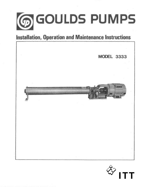
ITT Goulds Pumps 4XD 四尺非阻塞废水泵说明书

Goulds Pumps4XDSubmersible Explosion Proof Sewage Pumps4" Non-Clog X-Proof Sewage PumpFEATURESn Impeller: Cast iron, two vane closed design for high ef-ficiency and maximum wear life. Balanced for smooth operation. Optional bronze impeller available.n Bronze Wear Ring: Replaceable to renew the running clearances and efficiencies to original conditions.n Casing: Heavy duty cast iron, volute type for maximum efficiency . 4" 125# ANSI cast iron flanged. Adaptable to guide rail mounting system.n T andem Seals: T wo independently mounted mechanical face type seals are separated by an oil filled chamber . The oil chamber acts as a barrier to trap moisture and provide time for a planned shutdown and maintenance. The oil provides lubrication to the internal (upper) seal. Carbon rotating and ceramic sta-tionary faces are standard on both internal (upper) and external (lower) seals. Optional materials are available for the lower seals. See the Nomenclature Page for order number changes to order either silicon carbide/silicon carbide faces with Viton or silicon carbide/tung-sten carbide faces with Viton elastomers. These are recommended for applications containing fine solids or abrasives as found in parking lot/garage drainage and construction dewatering jobs.n Moisture Protection System: T wo-wire, dual mois-ture sensing probes are located in the oil filled chamber between the inner and outer seals. When connected to a control panel with an optional Moisture Detection System and an alarm it will detect the presence of moisture should the outer seal fail. It will also detect moisture in the motor chamber and provide a warning prior to water levels reaching the bearing or stator .n Designed for Continuous Operation: Motor is rated continuous duty submerged condition in water that is 40ºC or below . Maximum runtime with pump unsub-merged for 7½–40 HP is 15 minutes. Motor is suitable for 10 starts per hour .n Bearings: Ball, single-row , angular contact, Conrad type bearings with a Class 3 internal fit conforming to AFBMA Standard 20 are used. The bearings are greased for life with a premium moisture resistant polyurea thickened grease containing rust inhibitors and suitable for operation over a range of – 25º C to + 120º C.n Impeller Mounting Screw: 300 series stainless steel with anti-rotational locking patch.n Castings: All iron castings are ASTM A48 class 30 gray cast iron. Optional bronze impeller is ASTM B584 C87600 silicon bronze.Goulds Pumps is a brand of ITT Engineered for life2U L UnderwritersLaboratories MOTOR LISTED EXPLOSION PROOFCLaSS I, DIvISION I, GROuPS C & DAPPLICATIONS• Sewage systems• Flood and pollution control• Industrial dewatering• Wastewater treatment plants• Municipal and subdivision lift stations SPECIFICATIONSPump:• Solids handling capabilities: 3" maximum.• Discharge size: 4" 125# ANSI flanged.• Capacities: up to 1160 GPM.• Total heads: up to 140 feet.• Minimum flow: 100 GPM.• Maximum flow: end of published curve.• Mechanical seals: 304 stainless steel metal parts, BUNA- N elastomers with carbon/rotary and ceramic/stationary faces standard for upper and lower seals. Optional lower seals are available with Viton elastomers and either silicon carbide/ silicon carbide or silicon carbide/tungsten carbide faces.• Fasteners: 300 series stainless steel.Motor:•Explosion Proof Motor: Motors up to and including 40 HP are rated as Class F, 1.15 service factor and are certified explosion proof for Class I, Division I, Groups C and D locations.•CSA certified motors (Canadian Standards Association).•UL (Underwriters Laboratories) Listed Motors.•Three phase motors only.•Available voltages: 200, 230, 400, 460 and 575 volt, 60 Hz.•HP Range: 7.5 - 40.•Motor shaft is a one-piece design of high strength 416 stainless steel.•All motors are air-filled and designed for continuous duty when fully submerged or for up to 15 minutes operation in air.•NEMA design “B” with copper windings.•Class “F” stator winding designed for inverter duty.•Moisture System: Two wire dual probe monitoring system constantly monitors seal oil chamber and stator housing for moisture. Note: control panel must contain an alarm circuit and alarm device.•Two (2) normally-closed, automatic reset thermostats connected in series and embedded in adjoining phases.•Power and sensor cords are 25’ standard length, 50’ available as an option.•Motors conform to the latest applicable requirements of NEMA, IEEE, ANSI and NEC standards.NOTICE: Class 10 quick trip overload protection must be provided in control panel.1st Character – Discharge Size4 = 4” 125 # ANSI Discharge Flange2nd and 3rd Character – Pump Type / DesignXD = Explosion Proof, Dual Seal Pump with On-Winding Thermal Sensors and Moisture Detection Sensors 4th Character – Mechanical Seals1 = Standard Seal – the upper seal is carbon/ceramic,the lower seal is carbon/ceramic, BUNA and 304stainless steel metal parts.3 = Optional Lower Seal – silicon carbide/siliconcarbide, Viton elastomers and 304 SS metal parts.5 = Optional Lower Seal – silicon carbide/tungstencarbide, Viton elastomers and 304 SS metal parts. 5th Character – Motor RPM / Hertz2 = 1750 RPM / 60 Hz 6 = 1450 RPM / 50 Hz3 = 1150 RPM / 60 Hz6th Character – HorsepowerK = 7.5 M= 15 P = 25 R = 40L = 10 N = 20 Q = 307th Character – Voltage / Phase2 = 200 /34 = 460 / 3 6 = 380/400 / 33 = 230 / 3 5 = 575 / 38th Character – Impeller CodeA = 11.0” 10 HP 1150 RPM 40 HP 1750 RPM20 HP 1450 RPMB = 10.75” 30 HP 1750 RPMC = 10.38” 25 HP 1750 RPMD = 10.12” 7.5 HP 1150 RPM 15 HP 1450 RPME = 9.75” 20 HP 1750 RPMG = 9.00” 15 HP 1750 RPM 10 HP 1450 RPM K = 8.00” 10 HP 1750 RPM 7.5 HP 1450 RPM M = 7.50” 7.5 HP 1750 RPMT = SPECIAL TRIM9th Character – Cord Length - Power and Sensor Cords C = 25’ standard F = 50’ Optional10th Character – OptionsB = Silicon Bronze Impeller E = Epoxy PaintF = Both Bronze Impeller and Epoxy PaintNOMENCLATURE DESCRIPTIONSERIES 4XD(all ratings at 3 phase, 60 Hz. Consult factory for 3 phase, 50 Hz applications.)3Goulds Pumps and the ITT Engineered Blocks Symbol are registered trademarks and tradenames of ITT Corporation.SPECIFICaTIONS aRE SuBJECT TO CHaNGE WITHOuT NOTICE.B4XD August, 2008© 2008 ITT CorporationEngineered for lifeMaximum Solid Size3"Minimum Casing Thickness 5⁄16"Casing Corrosion Allowance 1⁄8"Maximum Working Pressure 100 PSI Maximum Submergence 200 feetMaximum Environmental Temperature40º C or 104º F ambient conditions.Maximum Starts Per Hour Maximum of 10 evenly spaced starts per hour.APPLICATION DATAPower Cable Type 1/0 / 4, 2/4, 4/4, 6/4, 8/4, 10/4, 12/4 SOW or SOOW(see Model Info).Control / Sensor Cable / Type 18/5 SOW.Power Cable and Leads have a BUNA N grommet in addition to being Cap Assembly epoxy encapsulated.Power and Control 25’ standard, 50’ optional.Cable Lengths Motor Enclosure Cast iron ASTM A-48 Class 30.Motor Shaft Series 416 Stainless steel.NEMA design “B” with copper windings and designed to Motor Designwithstand 200 psi water pressure at all seal locations. Air- filled NEMA 210TY frame on 7.5, 10, 15 and 20 HP models.Air-filled NEMA 250TYS frame on 25 - 40 HP models.Motor Insulation Rating Class "F" insulation.Motor Thermal Protection Two (2) normally closed on-winding thermostats open at320º F (160º C), automatic reset closes at 221º F (105º C).Motor Overload Protection Class 10, ambient compensated, quick-trip overloadprotection must be provided in control panel.Motor Moisture Protection Two (2) moisture sensing probes in the oil-filled sealchamber must be connected to a relay in control panel.CasingCast iron ASTM A-48 Class 30.Impeller Cast iron ASTM A-48 Class 30 or optional cast bronzeASTM B584 UNS C87600.Impeller TypeTwo vane enclosed design for maximum efficiency.Casing/Impeller/Wear Ring Replaceable bronze wear ring.External HardwareStainless steel.CONSTRUCTION DETAILSSTANDARD PARTSBall BearingsLubricated for life bearings are designed for aminimum L10 life of 30,000 hours .210 and 250 FrameSingle row Radial (upper). Single row Thrust (lower).Mechanical Seals – Upper Carbon/rotary and ceramic/stationary.Standard Lower Carbon/rotary and ceramic/stationary.Mechanical Seals – Lower Silicon carbide/rotary and tungsten carbide/stationary.Optional Lower Silicon carbide/rotary and silicon carbide/stationary.Standard Motor O-rings BUNA-N (nitrile)Premium moisture resistant polyurea thickened grease Seal Chamber Oil containing rust inhibitors is suitable for operation over a temperature range of - 25º C to +120º C.DIMENSIONS(All dimensions are in inches.Do not use for construction purposes.)。
ITT Goulds Pumps 泵操作指南说明书
If using a cartridge mechanical seal, the centering clips must be installed and set screws loosened prior to setting impeller clearance. Failure to do so could result in sparks, heat generation, and mechanical seal damage.
General precautions
General precautions
WARNING:
A pump is a pressure vessel with rotating parts that can be hazardous. Hazardous fluids may be contained by the pump including high temperature, flammable, acidic, caustic, explosive, and other risks. Operators and maintenance personnel must realize this and follow safety measures. Personal injuries will result if procedures outlined in this manual are not followed. ITT Goulds Pumps will not accept responsibility for physical injury, damage or delays caused by a failure to observe the instructions in this manual and the IOM provided with your equipment.
流程泵操作规程
流程泵操作规程【中英文实用版】Title: Flow Pump Operation Procedure1.Introduction:This document outlines the standard operating procedures for flow pumps.It is important to follow these instructions to ensure safe and efficient operation.1.介绍:本文件概述了流程泵的标准操作程序。
遵循这些说明对于确保安全、高效的运行至关重要。
2.Pre-Operation Checklist:Before starting the pump, perform a visual inspection to ensure all components are in good condition.Check the power supply and connections, as well as the pump"s alignment and lubrication.2.预操作检查清单:在启动泵之前,进行一次视觉检查,确保所有组件状况良好。
检查电源和连接,以及泵的对齐和润滑情况。
3.Operation:Turn on the power supply and gradually increase the pump"s speed to the desired setting.Monitor the pump"s performance and adjust as necessary.Regularly check for any signs of malfunction or abnormal operation.3.操作:开启电源,逐渐将泵的速度增加到所需设置。
监控泵的性能,如有必要进行调整。
百特输液泵操作流程
BAXTER输液泵操作流程
1 按ON/OFF开机
2 按下OPEN键
3 待下方屏幕显示“Patient->- >- >”,将蓝色夹放入凹槽中
注意:若蓝色夹方向不正确,则无法顺利将输液器置入
4 将管路顺势放入,下方屏幕显示“STOPPED”即表示输液器安装完成注意:待屏幕显示“Patient->- >- >”后,方可置入或取出输液器
5 选择“Primary→按Pump上的Rate输入所需的流速→按Pump上的V olume输入所需的容量→按“START”键即可开始输入
★输注中改变流速(Rate)
1按Pump上的Rate输入新数字
2 按“START”即可开始新的流速
★改变输注总量(V olume)
1 选择“Primary
2 按“Stop”键
3 按Pump上的V olume输入新的总量后,按主屏幕右下方之
“Confirm Setting”确认
4 按“START”键可开始输入
★记录已输注量
1 选择操作面板上方之“V olume History”
2 若需清除已输注的容量,请按屏幕下方“Clear Volume”
3 按主屏幕左下方之“Done”完成或Pump会自动跳回主画面。
JMS输液泵操作流程
二、改变模式只改变参数设置时
1.连续按“↓”键,翻到4/4页即第四页设置屏幕
2.按”键,选择Parameter参数,按回车键
3.进入参数设置:按“↓”键,选择需要设置的参数,按回车键,进入该参数的设置后,按“↓”键,选择需要的数值,按回车键,进入下一个参数的设置
六、打印记录
主菜单→文件管理器→选择单个记录或全部→点击打印键。
*备注
一导联连接质量显示
指示灯
说明
红色
表示导联故障或者极端基线偏离,显示相应的信息
黄色
表示肌肉人为影响、电极干扰、基线漂移或电极杂音,显示相应的信息
绿色
表示可接受的信号质量
二
速度
更改显示器上的移动速度以及打印输出的波形速度
增益
更改显示器上或报告中的信号幅度。单位越大波形越大,信号强度不受影响
4.开吸痰管包装,一次性无菌手套并连接负压,注意无菌操作。
5.管内吸痰:置入吸痰管时,关闭负压,将吸痰管迅速并轻柔送入气道,遇到阻力后再退后0.5cm,打开负压,边旋转边吸引一‘慢慢拔出吸痰管,每次吸引
时间不超过15秒。如遏痰液粘稠,可先将生理盐水沿导管壁注入后,再行吸痰。
6.鼻腔吸痰:气管内吸痰,冲洗吸痰管后,将患者口鼻分泌物吸净。
三、导出记录
主菜单→文件管理器→选择要导出的记录(按选择键,单个或全选)→点击更多→导出Hilltop→返回→导入→点击卡,查看是否已经导出至卡。
四、寻找记录
主菜单→文件管理器→搜索→输入搜索标准→点击搜索键。
五、删除记录
主菜单→文件管理器→删除单个记录,点击选择键,再用方向键选择要删除的记录(或点击全选键全部删除)→是或否→是。
高尔斯泵安装、操作和维护手册 Model HT 3196 i-FRAME说明书

安装、运行及维护手册
Model HT 3196 i-F.................................................................................................................................................................4 安全.....................................................................................................................................................................................4 安全警示等级...............................................................................................................................................................4 环境安全........................................................................................................................................................................4 用户健康与安全...........................................................................................................................................................5 易爆环境中防爆产品的安全规定...........................................................................................................................7 产品认证标准..................................................................................................................................................................8 CSA 合格证书..................................................................................................................................................................9 产品保修.........................................................................................................................................................................11
Bachmann界面使用手册

登陆成功后,若需要退出请点击左上角的
按钮,则会转入起始界面。
虚拟键盘:点击输入框即可弹出虚拟键盘如下图键盘按键包括
“A-Z,a-z,0-9,←(删除),回车(确认输入)Clr(清除所有),Del(删除后面的字
符),Ese(退出),SPC(包括键盘上所有字符……等和一些特殊字符)。默认主
要显示大写字母;选择 a-z 主要显示小些字母;选择 0-9 主要显示数字。输入
风力发电控制系统
界Байду номын сангаас使用手册
成都阜特科技有限公司 ChengDu Forward Technology Limited
2008-07-29 成都
目录
第一章 基础.....................................................4 第一节 登陆&注销..............................................4 第二节 人机界面结构...........................................5
第二章 主页......................................................7 第一节 运行状态...............................................7 第二节 安全链................................................15 第三节 统计..................................................16 第四节 I/O 查看 ..............................................20
JMS输液泵操作流程图

JMS输液泵操作流程开门→安装输液管路→按POWER键开机→按SET/CONFIRM调节每小时输入量→START/STOP开始按键注释:ADJUST----误差调零SELECT/IV SET----设置滴数/mlVOL CLEAR----清零START/STOP----运行/停止SET/CONFIRM----设置速度/液体总量POWER----电源开关VOL INFUSED LIMIT----查看已输入量PURGE----快速注入报警提示:AIR----空气OCCL----阻塞LOWBAT----低电量EMPTY----液体走空DOOR----泵门DRIP----滴数1. 按ON/OFF开机2. 按下OPEN键3. 待下方屏幕显示“Patient->- >- >”,将蓝色夹放入凹槽中注意:若蓝色夹方向不正确,则无法顺利将输液器置入4. 将管路顺势放入,下方屏幕显示“STOPPED”即表示输液器安装完成注意:待屏幕显示“Patient->- >- >”后,方可置入或取出输液器5. 选择“Primary→按Pump上的Rate输入所需的流速→按Pump上的Volume输入所需的容量→按“START”键即可开始输入★输注中改变流速(Rate)1)按Pump上的Rate输入新数字2) 按“START”即可开始新的流速★改变输注总量(Volume)1) 选择“Primary2) 按“Stop”键3) 按Pump上的Volume输入新的总量后,按主屏幕右下方之“Confirm Setting”确认4) 按“START”键可开始输入★记录已输注量1. 选择操作面板上方之“Volume History”2. 若需清除已输注的容量,请按屏幕下方“Clear Volume”3. 按主屏幕左下方之“Done”完成或Pump会自动跳回主画面安装注射器→ON→MODE(模式)→按▼键→CONFIRM(确认)→按▼键→出现T/→CONFIRM(确认)→出现60或20→CONFIRM(确认)→RATE→输入数值→CONFIRM(确认)→VOL LIMIT(总量要或等于小于60ml)→输入数值→CONFIRM(确认)→START→CONFIRM(确认)备注:1 改变剂量:不需停止,按EDIT→显示RATE→输入数值→确认2 输入错误数值后按CLR键即可清除,再输入正常数值3 快速泵入:BOLUS→EDIT→显示RATE→输入数值→确认→START除颤器的使用说明一、适应症:主要是应用于室颤引起的循环功能衰竭,对于不明原因的心脏骤停也可盲目除颤,以争取时间,提高抢救功率。
格兰富循环水泵使用说明
格兰富循环水泵使用说明嘿,朋友们,今天咱们聊聊格兰富循环水泵,听起来很专业是不是?别担心,我来给你捋捋,保证你听了能点头称是。
咱们得知道,格兰富可是大名鼎鼎的品牌,它的水泵在业内可算是数一数二的。
想象一下,那种流畅的水流,就像小溪流水潺潺,瞬间让你的生活质量提升好几个档次。
用对了水泵,家里就像开了水上乐园,嘿嘿。
好了,咱们先说说这循环水泵的基本原理。
其实说白了,就是让水在管道里不断循环,保持水温稳定。
就像一位勤劳的小蜜蜂,不停地在花间飞舞。
说到这里,可能有人会问,水泵要怎么用啊?别急,接下来我就来给你详细说说,保证你听完就能立马上手。
安装是个关键,咱们得找个平整的地方,把水泵摆放稳妥。
注意别让它受潮,要不然可就麻烦了。
水泵的进出水口要连接好,记得用点儿密封胶,这样才能防止漏水。
万一漏水了,那可真是“马失前蹄”,搞得你满地都是水,家里简直就成了“水世界”了。
接下来是电源的部分,嘿,这里可得小心,电可不是好惹的。
插头插紧了,确保没有松动,这样才能保证水泵正常工作。
启动的时候,咱们要稍微等一下,让它把水抽上来,那个声音,像极了清晨的鸟鸣,活力满满。
看到水流顺畅,就像看到孩子们开心地玩耍,那种感觉,真是太爽了。
不过,有一点要注意,水泵工作时别打扰它,毕竟它也需要专注工作嘛。
然后,有些朋友可能会问,这水泵的保养该怎么做?其实很简单,定期检查是关键。
每隔一段时间,打开水泵看看有没有杂质,如果有,那就得清理一下。
别让水泵累坏了,心疼得很。
顺便说一句,别让水泵空转,空转就像是让一位艺术家没有画布,那种无奈真是让人心痛。
记得定期给水泵加点润滑油,就像给汽车加油,能让它跑得更顺畅,嗖的一声,咱们的水泵就能好好工作。
说到这里,有没有感觉水泵其实也是个小精灵呢?它默默无闻,却为我们的生活带来了便利。
不过,万一遇到问题,别慌,看看说明书,通常能找到解决办法。
如果还是搞不定,那就找专业的维修人员吧,别硬撑,毕竟“不到黄河心不死”,心大了可就容易出事。
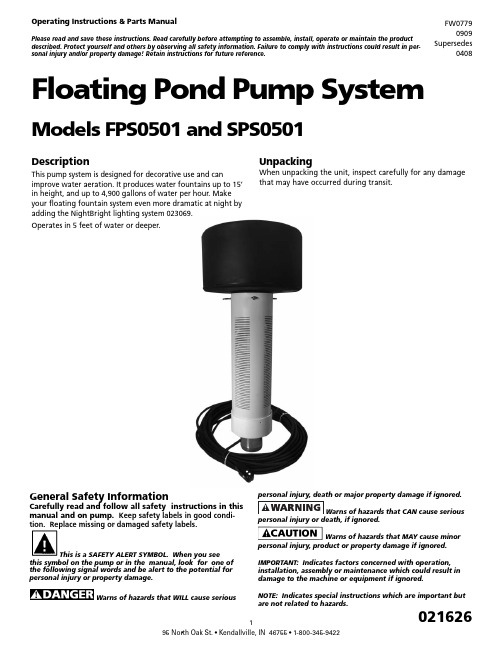
潮流北美漂浮池水泵系统操作说明及零件手册说明书
DescriptionThis pump system is designed for decorative use and canimprove water aeration. It produces water fountains up to 15’ in height, and up to 4,900 gallons of water per hour. Make your floating fountain system even more dramatic at night by adding the NightBright lighting system 023069.Operates in 5 feet of water or deeper.UnpackingWhen unpacking the unit, inspect carefully for any damage that may have occurred during transit.Floating Pond Pump SystemModels FPS0501 and SPS0501Operating Instructions & Parts ManualPlease read and save these instructions. Read carefully before attempting to assemble, install, operate or maintain the product described. Protect yourself and others by observing all safety information. Failure to comply with instructions could result in per-sonal injury and/or property damage! Retain instructions for future reference.FW07790909 Supersedes0408General Safety InformationCarefully read and follow all safety instructions in this manual and on pump. Keep safety labels in good condi-tion. Replace missing or damaged safety labels.This is a SAFETY ALERT SYMBOL. When you seethis symbol on the pump or in the manual, look for one of the following signal words and be alert to the potential for personal injury or property damage.Warns of hazards that WILL cause seriouspersonal injury or death, if ignored.Warns of hazards that MAY cause minorpersonal injury, product or property damage if ignored.IMPORTANT: Indicates factors concerned with operation, installation, assembly or maintenance which could result in damage to the machine or equipment if ignored.NOTE: Indicates special instructions which are important but are not related to hazards.Never enter the watereither wading, swimming or in a boat with thepump power on, as this may result in severecarefully. Failure to follow could result in serious bodilyinjury and/or property damage.shall be in accordance with National ElectricCode (NEC) and all applicable local codesand ordinances. A licensed electrician shouldperform installation.“NO SWIMMING” ANDOR WARNING SIGNS SHOULD BE POSTED PERSTATE AND LOCAL CODES.Please affix included warning label to powerreceptacle or junction box.100ft power cord with three prong GFI plug. –Must connect to properly grounded receptacleof grounding type. Do not remove groundpin on plug. Do not extend the cord length by splicing orTHIS UNIT, WITH THE GFI, TO A PROPERLYGROUNDED RECEPTACLE MAY RESULT INto a circuit equipped with a fuse or circuitbreaker of ample capacity.Always disconnect powersource before performing any work on ornear the motor or its connected load. If thepower disconnect point is out-of-sight, lock itin the open position and/or tag it to prevent unexpectedapplication of power. Failure to do so could result in fatalelectrical shock or bodily injury.DO NOT handle pump withwet hands or when standing in water asfatal electrical shock could occur. Disconnectmain power supply before handling systemfor any reason.from coming in contact with sharp objects,oil, grease, hot surfaces or chemicals. DONOT kink the power cable. If damagedbox, fused disconnect switch, or covers open(either partially or completely) when notbeing worked on by a competent electricianor repairman.Always use caution whenoperating electrical controls in damp areas.If possible, avoid all contact with electricalequipment during thunderstorms or extremedamp conditions.equipment in protected area to preventmechanical damage which could produce seriouselectrical shock and/or equipment failure.DO NOT use this system topump flammable liquids such as gasoline, fueloil, kerosene, etc. Failure to follow the abovewarning could result in property damage and/or personal injury.Do not pump water above 120 degreesFahrenheit.Water leaving nozzle is at high velocityand can cause bodily injury if contact is made.in swimming pool areas.!to the State of California to cause cancer and birth defects orother reproductive harm.!coming out the bottom and protected from direct rainfall.INSTALLATION INSTRUCTIONS1. Only install this system in ponds where no swimming,wading, boating or fishing is allowed while fountain isoperating. Disconnect power to pump before fishing orentering the water.2. Post appropriate warning signs per local and state codes.3. Inspect pump system for damage before installing inpond. Check that all bolts and screws are tight. Check forany bent prongs or a cracked case on the GFI.4. The unit ships with one spray nozzle attached. To changeto one of the other 2 nozzles, remove the 4 screws fromthe nozzle then replace with desired nozzle. Refer toFigures 1, 2 & 3 for spray pattern appearance. Nozzlesare marked “This side up.” Make sure the o-ring isseated in groove before installing nozzle. Tighten screwsuntil seated, approximately 10 to 12 in-lbs.5. Attach nylon anchor ropes to 3 eyebolts located at topof screen. Secure (make sure rope is tight) to weightsplaced on pond floor or stakes on pond shore. Whenusing weights to anchor the pump, place weightsapproximately 10 feet from unit. Alternately, two anchorropes placed 180 degrees apart can be used, but 3 ropeswill provide the best stability.6. Before connecting the unit to the power receptacle,check to insure there is no leakage to ground. This canbe done by using an ohm meter and setting the scale toits highest setting (i.e. Rx100K). Connect one ohmmeter lead to the unit power cord ground (round prong) and to one of the flat prongs. It should read infinite or at least 2 mega ohms. Repeat with the other prong. If reading is below 2 mega ohms on either prong contact Customer Service Help Line listed at bottom of page.7. Do Not Operate System on an Extension Cord. If no power is accessible at the pond, contract a licensed electrician to install the proper power supply in accordance with National Electric Code and all applicable local codes and ordinances.8. After installing the unit, checking ground andconnecting power to the unit, the unit can be powered up. Check operation of the GFI by pushing the “Test” button, the unit should stop. Pushing the “Reset” button should restart the unit. If pressing the “test” button does not stop the unit, immediately shut off power to unit and contact Customer Service Help Line listed at bottom of page.NOZZLE PATTERNST h is s id eu p Figure 1: Water Lily - An eye-catching combination spray. Item #2AT h i s s id eu pFigure 2: Sky Cannon - A dramatic single plume of water. Item #2BT h i s s id eu pFigure 3: Water Trumpet - A symmetrical inverted bell shape.Item #2CFigure 4: Typical InstallationINSTALLATION CHECK LIST☐ Read installation instructions and warnings ☐ Post appropriate warning signs ☐ Install desired spray nozzle ☐ Install and anchor unit in pond☐ Check insulation resistance to ground ☐ Power up unit☐ Test operation of GFI by pressing the “Test” Button.☐ File instructions for future reference REQUIRED TOOLS & SUPPLIES• #2 Phillips screwdriver • Nylon rope to anchor unit• Stakes or weights for anchoring unit• Ohm meter to check insulation resistance to groundWINTER STORAGE• Rinse unit with clean water to remove any build-up on unit.• Check unit for any damage.• Store unit in heated space in freezing climates.The pump motor is water lubricated and is factory filledwith an antifreeze solution. During operation the antifreeze may exchange, thru the filtered check valve, with the pond water. In climates where freezing may occur, the unit must be stored in a heated storage space to prevent damage to the motor.TROUBLESHOOTING GUIDE PROBLEM POSSIBLECAUSESCORRECTIVE ACTIONUnit won’t run Circuit break-er trippedReset circuit breaker GFI Tripped Reset GFINo or low spray Blockedscreen ornozzle, miss-ing or dam-aged o-ring,or incorrectlyinstallednozzleDisconnect power. Clean screenand/or nozzle. Check that o-ring isundamaged and seated in groove.Check that nozzle is installed prop-erly (nozzles are marked “This sideup”). Check depth of pond. If lessthan 5 feet deep, move to deepersection. Restart unit.GFI Trips Electricalstorm can tripGFIReset GFIShort in sys-tem Disconnect power and check cord for damage. If cord is damaged contact Customer Service Help Line listed at bottom of page for replacement.Unit spins Anchor ropeloose Check anchor rope and re-attach if necessaryItem #Qty Part No.Description16021624Screw - #10 x 3/4 Pan Head High-Low 2A1021617Nozzle - Water Lily2B1021618Nozzle - Sky Cannon2C1021619Nozzle - Water Trumpet31021622O-Ring - AS568A - 041 (3” ID x 3/18” OD) 44021628Bolt - SS 1/4-20 x 3/454021629Lockwasher - 1/4”61021707Mounting Flange71021534Float81021713Pump End91021740Motor 1/2 HP 115V104127021Locknut - SS 5/16-24111021715100 ft. power cord with GFI11A1021614GFI123021609Eye Bolt - SS 1/4-20 x 2-1/2133021623Locknut - SS 1/4--20141021608Screen151021611Screen Cap161021613Strain Relief172021625Warning DecalFlow (GPH)Spray Height(Ft.)PatternImagePatternName 490015Thissi de upIL053Thissi de upThissi de upWater Lily- 2A 330015Sky Cannon- 2B 270013WaterTrumpet - 2C15161112(A/B/C)345671710911131214811A。
朗克赛特变量体积泵用户手册说明书

PVP Series Variable Volume Piston Pump Service Bulletin Model PVP16 **** 12Bulletin PM 1620-12-M1/USA Parker PumpsParts & ServiceRevised:May 1998HydraulicsParker Hannifin CorporationHydraulic Pump/Motor Division Greeneville, TN 37745 USAParker Hannifin CorporationHydraulic Pump/Motor Division Greeneville, TN 37745 USABulletin PM 1620-12-M1/USAParker Pumps Parts & Service Model PVP16 **** 12Pump Cut-A-Way ..................................................................................4 - 5Control Options (6)Thru Shaft Options (7)Exploded View .....................................................................................8 - 9Parts List.................................................................................10 - 11Service Notes . (12)Basic Troubleshooting (12)Offer of Sale (15)Introduction:The PVP16 **** 12 series piston pumps are designed to provide long life while operating with Hydraulic Oil. Refer to catalog 1550/USA for limits. However, should maintenance be required, the followinginstructions should be used for disassembly, replacement of parts, cleaning and assembly.Note:Prior to any pump disassembly, plug the open ports and clean all dirt from the outside ofthe pump.Prior to assembly all parts should be cleaned and then lightly coated with oil.Warning:Protective eye wear should be worn during all maintenance procedures.Table of ContentsBulletin PM 1620-12-M1/USAParker Pumps Parts & Service Model PVP16 **** 12Parker Hannifin CorporationHydraulic Pump/Motor Division Greeneville, TN 37745 USA4Pump Cut-A-WayParker Hannifin CorporationHydraulic Pump/Motor DivisionGreeneville, TN 37745 USA5Bulletin PM 1620-12-M1/USAParker Pumps Parts & Service Model PVP16 **** 12Pump Cut-A-WayBulletin PM 1620-12-M1/USAParker Pumps Parts & Service Model PVP16 **** 12Parker Hannifin CorporationHydraulic Pump/Motor Division Greeneville, TN 37745 USA6Control OptionsParker Hannifin CorporationHydraulic Pump/Motor DivisionGreeneville, TN 37745 USA7Bulletin PM 1620-12-M1/USAParker Pumps Parts & Service Model PVP16 **** 12Thru Shaft OptionsBulletin PM 1620-12-M1/USAParker Pumps Parts & Service Model PVP16 **** 12Parker Hannifin CorporationHydraulic Pump/Motor Division Greeneville, TN 37745 USA8Pump Exploded ViewParker Hannifin CorporationHydraulic Pump/Motor DivisionGreeneville, TN 37745 USA9Bulletin PM 1620-12-M1/USAParker Pumps Parts & Service Model PVP16 **** 12Pump Exploded ViewBulletin PM 1620-12-M1/USAParker Pumps Parts & Service Model PVP16 **** 12Parker Hannifin CorporationHydraulic Pump/Motor Division Greeneville, TN 37745 USA10Parts ListParker Hannifin CorporationHydraulic Pump/Motor Division Greeneville, TN 37745 USA11Bulletin PM 1620-12-M1/USA Parker Pumps Parts & Service Model PVP16 **** 12Parts ListBulletin PM 1620-12-M1/USAParker Pumps Parts & Service Model PVP16 **** 12Parker Hannifin CorporationHydraulic Pump/Motor Division Greeneville, TN 37745 USA12Service Notes & Basic Troubleshooting Service Notes:l Use a clean lubricant (compatible with the working fluid) on all pump components during assembly.lMost premature pump failures occur whencontaminants from a previous failure have not been removed from the system, or cause for previous failure is still present (i.e. water in oil, filter bypassing, etc.)l Thoroughly clean the reservoir, suction lines, suction strainer, drain lines, etc. before re-installing the pump.lAlways fill the pump case with clean fluid before starting a new or serviced pump for flooded suction,purge air from suction lines by cracking the inlet fitting or vent plug on pump. This should prevent an airlock condition and allow for faster priming.lStarting the pump slowly by jogging (or turning over engine without allowing it to start) will help the pump prime and make it easier to determine when priming has occurred.lStart pump with an open circuit whenever possible.Reduce the compensator to it's minimum setting during start-up. Cycle the pump on and off stroke while increasing the compensator to its required setting.This will assist in break-in of new components and help purge air from the case.Basic Troubleshooting:Pump Will Not Prime∆Pump should prime within 30 seconds. If it does not,STOP .∆Check for proper drive rotation.∆Make sure pump shaft is turning (i.e. key at couplinghubs is engaged).∆Make sure reservoir is full.∆Check for major sources of a suction leak (vent plugopen, shaft seal missing (PAVC), flange not tight,pinched O-Ring at flange or pump housing.Cannot Build Any Pressure ∆Make sure pump is primed.∆Check alignment, especially on PAVC pumpswithout "9" option.∆Make sure systems is not an open circuit.A pump produces flow, not pressure. It can only limit pressure when the system requirement is higher than the pump compensator setting.Can Only Build A Few Hundred PSI∆Compensator is backed all the way out.∆The remote or load sense line is vented.∆Control orifice or spool is plugged.∆Incorrect compensator spool (PVP).∆Pressure control dart is lodged open.∆Torque control plug is missing (PAVC).Pump Will Not Compensate∆Differential spring over-compressed (i.e. springguide dislocated).∆Control drain line blocked (PAVC).∆Pressure control stem vent hole is plugged.∆Control spool travel is hindered.∆Control orifice is missing (PAVC).∆Saturation orifice is missing in load sense circuit.Parker Hannifin CorporationHydraulic Pump/Motor Division Greeneville, TN 37745 USA13Bulletin PM 1620-12-M1/USAParker Pumps Parts & Service Model PVP16 **** 12Notes:Bulletin PM 1620-12-M1/USAParker Pumps Parts & Service Model PVP16 **** 12Parker Hannifin CorporationHydraulic Pump/Motor Division Greeneville, TN 37745 USA14Notes:Parker Hannifin CorporationHydraulic Pump/Motor Division Greeneville, TN 37745 USA15Parker Hannifin CorporationHydraulic Pump/Motor Division 2745 Snapps Ferry Road Greeneville, TN 37745 USA Tel. (423) 639-8151FAX (423) 787-2418Web site: 5/98 DBHESS 5000。
手术室恒速泵操作流程

手术室恒速泵操作流程英文回答:Operating Room Infusion Pump Operating Procedure.As an operating room nurse, one of my responsibilities is to operate the infusion pump during surgeries. The infusion pump is a crucial piece of equipment that delivers medications, fluids, and blood products to patients at a controlled rate. It ensures that the patient receives the correct dosage and maintains a steady flow throughout the procedure. In this response, I will outline the step-by-step process of operating the infusion pump in the operating room.1. Preparation:Before starting the surgery, I ensure that the infusion pump is clean and properly functioning. I checkfor any visible damage or signs of malfunction.I gather all the necessary supplies, including the medication or fluid to be infused, the appropriate tubing, and the patient's identification band.I verify the medication or fluid order with the surgeon and double-check the dosage and rate of infusion.2. Programming the Pump:I turn on the infusion pump and select the appropriate mode of operation, such as continuous infusion or intermittent infusion.Using the keypad or touchscreen, I enter thepatient's information, including their name, medical record number, and weight if required.I then input the medication or fluid name, dosage, and rate of infusion. The pump may have pre-set options for commonly used medications, which can save time.After programming the pump, I review the settings to ensure accuracy and make any necessary adjustments.3. Priming the Tubing:Before connecting the tubing to the patient, I prime it with the medication or fluid to remove any air bubbles and ensure a smooth flow.I connect the tubing to the appropriate port on the infusion pump and follow the manufacturer's instructionsfor priming.Once the tubing is primed, I check for any leaks or kinks that could disrupt the flow.4. Connecting to the Patient:I identify the correct access point for infusion, such as a peripheral intravenous (IV) line or a central venous catheter.Using aseptic technique, I clean the access point with an antiseptic solution and allow it to dry.I connect the tubing to the access point, ensuring a secure connection.I double-check that the tubing is not obstructed and that the flow rate is appropriate for the patient's condition.5. Monitoring and Troubleshooting:Throughout the surgery, I closely monitor the infusion pump and the patient's response to the medication or fluid.I observe the flow rate, any alarms or alerts on the pump, and the patient's vital signs.If an alarm sounds or there are any issues with the infusion, I troubleshoot the problem immediately. This may involve checking for occlusions, adjusting the tubing, ornotifying the anesthesia provider or surgeon.6. Documentation:After the surgery, I document the details of the infusion in the patient's medical record. This includes the medication or fluid administered, the dosage, the rate of infusion, and any observations or interventions made during the procedure.中文回答:手术室恒速泵操作流程。
高效液相色谱使用详细操作步骤之欧阳总创编

高效液相色谱使用操作步骤一、泵操作面板PUMP:运行键 START:梯度运行键 PURGE:快冲键RESET:复位键 HOLD:程序暂停键 STOP:泵停止键TIME:程序开启键 FLOW:流速: RSVR: A B C PROG:程序 DEL:删除程序 PMAX:最大压力PMIN:最小压力 ENTER:确定TIME 0 FLOW ENTER (设置流速)TIME 0 RSVR ABC ENTER (设置溶剂)TIME 0 PROG ENTER (设置程序)TIME 0 % A 30 ENTER (设置比例)TIME 0 % B 30 ENTER (设置比例)TIME 0 % C 40 ENTER (设置比例)DEL PROG 1 ENTER (删除程序)1.对于梯度泵设定举例如下:(人参皂苷的梯度)TIME 0 PROG 1 ENTERTIME 0 % A 81 ENTERTIME 15 % A 81 ENTERTIME 60 % A 65 ENTERTIME 65 % A 0 ENTERTIME 80 % A 0 ENTERTIME 81 % A 81 ENTERTIME 100 % A 81 ENTER因为A+B之和始终是100%,所以B相就不用设了。
7.对于对照品在这种条件下只要对照品的峰全部出完后按下RESET键等20分钟即可进第二针进完针后按START 键运行梯度程序。
但是对样品来说一定要等峰出完后再按下RESET键等基线基走直才可进下一针。
二、检测器操作面板RESET:复位键 A/Z:调零键 WL:调波长 ENTER:确定三、实验前的准备工作1、实验前流动相提前配好过滤脱气。
2、置换流动相时把泵的滤头从原来的流动相中换到新的流动相中滤头要轻拿轻放。
3、液路排气顺序:首先打开排气阀—按PURGE键进行排气结束后—按STOP键停止—再拧紧排气阀—按PUMP键让泵运行。
4、打开检测器首先观察右上角氘灯指示灯确认氘灯是否点亮,按WL键调好实验波长后按A/Z键调零。
浦发泵操作说明书
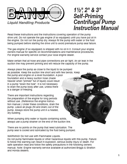
Read these instructions and the instructions covering operation of the pumpdrive unit. Do not operate the gas engine (if so equipped) until you have put oil in the engine. Do not run the pump dry. Always fill the pump with water or the fluid being pumped before starting the drive unit to avoid premature pump seal failure.The gas engine (if so equipped) is shipped with no oil in it. Consult your engine owners manual for specific oil recommendations and maintenance procedures. For engine warranty service contact your local engine dealer.Make certain that all hose and pipe connections are air tight. An air leak in the suction line may prevent priming and will reduce the capacity of the pump. Always place the pump as close to the liquid to be pumpedasas possible. Keep the suction line short and with few bends. Keep the pump and engine on a level foundation. A poor foundation and a heavy suction hose (made heavier when “primed” full of liquid) could result in a pump “down the hole”. It is not necessary to drain the pump body after use, unless there is a danger of freezing.There are important instructions regarding the preparation of the engine for long periods without use. (Reference the engine instruc-tion manual.) Under these conditions, drain the pump. Leave all plugs (fill and drain) out of the pump. Always store the pump unit in a heated, dry building.When pumping dirty water or liquids containing solids, always use a pump strainer on the end of the suction line.There are no points on the pump that need lubrication. The pumppump seal is cooled and lubricated by the fluid being pumped.WARNING! Do Not use with Flammable Liquids.Do not pump flammable liquids or other hazardous liquids with this pump. Failure to follow this warning can result in explosion, serious bodily injury or death. For safe operation read and follow the safety precautions in the following owners manual. Note: Engine warranty service available at authorized Briggs & Stratton and Honda dealers.1½", 2" & 3" Self-Priming Centrifugal Pump Instruction ManualD ISASSEMBLY I NSTRUCTIONS :1. Remove the 10 body screws (12720), lock washers (V07018) and nuts (V07019) from the pump assembly. Remove the body from the pump assembly.2. Remove the check valve (12705) from the volute (12702A). Remove the one upper volute screw (12900) and the two smaller volute screws (12725) from the volute. Remove the volute from the remaining pump assembly.For 3" PUMPRemove the check valve (12705) from the volute (13702). Remove the one upper volute screw(12900) and the two smaller volute screws (12725) from the volute. Remove the volute from the remaining pump assembly.3. Remove the impeller bolt (12765A) from the impeller (12771A/12772). Remove the impeller bolt gasket (12774VA) from the impeller.For 3" PUMPRemove the impeller bolt (12765A) from theimpeller (13772). Remove the impeller bolt gasket(12774VA) from the impeller.1224. Screw the supplied 7/16-14 hex head cap screw into the impeller snout. As the bolt is tightened the impeller will be pried off of the shaft of the drive unit. Remove the 7/16-14 screw once the impeller has been removed from the drive unit.If the pump impeller is going to be reused the ceramic seal half (12713) should be removed from the impeller at this time. The impeller key (12902A) located behind the ceramic seal half should be replaced at this time also.5. Remove the four bracket screws (12715A), rear bracket washers (12901), and screw head O-rings (12717) from the rear bracket using a ½" socket. With the four bracket screws removed the rear bracket can now be removed from the drive unit.6. Remove the carbon seal half from the rear bracket. This may be done by using a round object such as a wrench socket and tapping it gently with a hammer. The seal is very fragile so take care not to crack the seal if it will be reused. With the pump completely disassembled; clean all of the reusable parts thoroughly, removing any traces of old gasket material and trapped or dried liquids that were run through the pump.At this time, it may be necessary to polish the drive unit shaft to remove any corrosion that may haveformed.456A SSEMBLY I NSTRUCTIONS1. Install the pump slinger (12706) on to the drive unit shaft. The slinger should be slid all the way back on the shaft of the drive unit so that the slinger covers the step on the drive unit shaft as shown.3. Place the seal O-ring (12710) behind the lip of the carbon seal half. The carbon seal half (12713) should now be installed into the rear bracket as shown at right.3. To install the carbon seal half into the rear bracket use a tool such as a 1 ½" pipe nipple or arbor press to give even pressure on the metal flange of the seal housing during installation. Gently press the seal into position until it bottoms.4. Clean the threads of the bracket screws (12715A) thoroughly. Once clean, install the four flat washers (12901) and four screw head O-rings (12717) onto each of the bracket screws.11345. Install the rear bracket onto the drive unit using the bracket screw assemblies from the previous step. The handle of the rear bracket should be to the top of the drive unit. Tighten the screws securely.6. Verify that the impeller hex nut (12775A) is located at the bottom of the impeller snout, itshould be installed now. A very light press fit may be required to install the nut into its cavity.Install the ceramic seal half into the impeller. The seal half is pressed into the hub of theimpeller by using an arbor press or similar tool that will provide a uniform press fit. The outside diameter of the rubber boot may be sparingly coated with silicone to ease installation. Be absolutely sure that the ceramic seal half is bottomed out and installed squarely. If theinstallation is not square, seal wobble will occur leading to premature seal failure. Care must be used when handling the seal to not scratch the seal surface.7. Place the impeller key (12902A) in the slot located inside the impeller snout. The impeller (12771A/12772) is now ready to be slid onto the drive unit shaft.8. Secure the impeller to the drive unit shaft with the impeller bolt gasket (12774VA) and impeller bolt (12765A). Tighten the impeller bolt until snug.For 3" PUMPPlace the impeller key (12902A) in the slot located inside the impeller snout. The impeller (13772) is now ready to be slid onto the drive unit shaft. Secure the impeller to the drive unit shaft with the impeller bolt gasket (12774VA) and impeller bolt (12765A). Tighten the impeller bolt until snug.57bracket as shown.10. Install the volute (12702A) onto the rearbracket using the three volute screws (1-(12900), 20(12725)). Install the check valve (12705) onto the snout of the volute. The drive unit should be turned over a few times to check for clearance between the impeller and volute. A small amount of drag between the impeller and volute will cause no problem, however, if the drive unit will not turn over because of the lack of clearance a bracket shim may have to be used.For 3" PUMPInstall the volute (13702) onto the rearbracket using the three volute screws (1-(12900), 20(12725)). Install the check valve (12705) onto the snout of the volute. The drive unit should be turned over a few times to check for clearance between the impeller and volute. A small amount of drag between the impeller and volute will cause no problem, however, if the drive unit will not turn over because of the lack of clearance a bracket shim may have to be used.101011. Place the pump body O-ring (12719A) around the outside flange of the rear bracket. The O-ring may be sparingly lubricated with silicone to ease installation of the pump body in the next step.12. Install the pump body (12712) as shown below with the outlet flange facing up. Install the 10 body screws (12720), 10 lock washers (V07018), and 10 nuts (V07019) to secure the pump body to the rear bracket. Tighten the bolts securely all the way around.For 3" PUMP12. Install the pump body (13712) with theoutlet flange facing up. Install the 10 body screws (12720), 10 lock washers (V07018), and 10 nuts (V07019) to secure the pump body to the rear bracket. Tighten the bolts securely all the way around.The pump is now ready for operation.1112(Viton & Buna Seals available upon request.。
贝朗注射泵产品 -操作说明课件

Perfusor® compact S
10 ml
F
ml/h
1
=?
STANDBY
78 9
0
|
S ml - +
4 56
C
START
F STOP
BOL
|ml
P
1 23
2 OPS 50ml
Omnifix® 10ml
30
特别功能 :快速推注功能
快推管理功能只能用于机器运行时!
在停止状态下,BOLUS 键可用于输液前排气,这种情况 下输注的液体量不会被算在总的已输注容量中。
Perfusor® compact S
=?
1STANDBY
78 9
0
F
|
S ml - +
4 56
C
START
F STOP
3
BOL
|ml
P
1 23
OPS 50ml
Omnifix® 10ml
15
开始标准操作
Perfusor® compact S
10 ml
ml/h
=?
STANDBY
78 9
0
|
S ml - +
BOL
|ml
P
1 23
OPS 50ml
1 3
1
2
9
标准操作: 放置注射器
-放稳注射器后推杆锁回位(1) 听到吧嗒一声,提示驱动装置已回位。
-关闭针筒夹(2)
Perfusor® compact S
=?
STANDBY
78 9
0
F
|
S ml - +
4 56
C
WATERAX BB-4-21 快速指南说明书

This Quick Guide shows the basic operation of the WATERAX BB-4-21 4-stage high pressure pump..• T he WATERAX BB-4 pump model pairs a WATERAX 4-stage pump end with a Honda GX630 gasoline engine. For engine instructions, oil and fuel recommendations, please refer to the engine manufacturer’s manual.• F or detailed instructions on using and troubleshooting your pump, as well as full service and maintenance instructions, refer to our website to download the BB-4 Owner’s Manual.• F or full specifications and performance curves, see the BB-4-21 Data SheetWarnings and Safety PrecautionsThis warning label appears on all WATERAX pumps to identify safetyhazards as follows:READ YOUR ENGINE MANUAL!Before proceeding further, locate and read the engine manufacturer’s manual. It contains very important safety information that MUST be read, understood and followed to safeguard you and your equipment from harm, as well as for the proper use and care of your engine. Use only fuel and oil type recommended in the engine manufacturer’s manual. Always check oil level in crankcase before use.GENERAL WARNINGS :• Do not operate if mentally/physically fatigued. • Inspect hoses and piping to avoid burst injuries.• No modifications and/or alterations may be made to the pump. Any such modifications void the pump warranty and can endanger pump operators.•Do not operate the pump above the maximum rated pressure. Use only pipe, hose, and fittings rated at or above the maximum pressure rating of the pump or system design.• Slowly close valves. Use slow close valves wherever possible to safeguard operators and prevent damage from water hammer.•Dry weight of the unit: 169 lbs (will vary depending onoptions).WEAR EAR AND EYE PROTECTION.Always wear eye and ear protection when operating thepump unit. Sound level of the unit: 92 dB(A).READ THE PUMP OWNER’S MANUAL!The improper use of this pump could result in serious injuries as well as damage to the unit. Read the BB-4 Owner’s Manual before using your BB-4 pump unit and follow the safety instructions in this Quick Guide.REFUEL ENGINE WITH CARE . Gasoline is extremely flammable, and gasoline vapor can explode. Refuel in a well-ventilated area, with theengine stopped.NEVER RUN THE ENGINE IN A CLOSED OR CONFINED AREA . Exhaust gas contains carbon monoxide which is poisonous to humans. Avoid inhalation of exhaust gas.NEVER TOUCH ANY EXHAUST SYSTEM PARTS WHILE ENGINE IS RUNNING . Always allow enough time, after stopping the unit, for propercooling of the muffler and surrounding parts.EQUIPMENT DAMAGE PREVENTION: • Flush the pump with fresh water if the pump has been used to pump salty, brackish, high mineral content water, water containing debris, or foam injected water. Check that debris is cleared before using the pump again.Always draft water using a suction hose strainer.•Parts IdentificationA. Priming capB. Pump intake (suction)C. Pump drain port (not shown)D. Pump dischargeE. Quick release pump clampF. MufflerG. Starter key switch (not shown) H. Choke (not shown) I.ThrottleABDFGH ICETo operate the BB-4-21 unit:Fill fuel tank with recommended fuel grade andsecurely replace cap. Check oil (see engine manual).2.1. Connect the suction hose , using a universal hosecoupling wrench to tighten coupling firmly:Drafting Mode : Connect footvalve strainer to male end of suction hose, then fill suction hose with water andPriming PortSuction/Intake PortDischarge PortFlooded Suction Mode : Connect female end of suction hose to pump intake and connect male end to hydrant or other supply.a. Slowly open the pump inlet valves allowing thewater into the pump body.b. Slowly open the discharge valves and primingvalves to allow for entrapped air in the piping to escape.c. Once all the air has escaped, slowly close anyopened valves so that the unit may be started.3. Connect discharge hose, nozzles, etc., to pump , andtighten firmly with coupling wrench.4. Prime the pump.Check that all drains, discharge valves, or anyauxiliary valves are closed before priming the pump. Open the priming ball valve (located between the pump and the primer).Manual Priming: Open the priming cap and fill pump with water manually. Firmly tighten priming cap. Pump can also be primed by “jerking” the suctionhose until water flows from the pump’s discharge port. Guzzler Priming: If equipped with a Guzzler primer, follow the hand pump manufacturer’s operationinstructions. Pump until water is drawn into the pump. Electric Priming: See instructions for your electric primer. Note that most electric primer motors are intended to be used only a short duration (about 20 seconds). If pump fails to prime, see theBB-4 Owner’s Manual for troubleshooting tips. Close the priming valve after priming. Failure to close the priming valve could cause the pump to lose prime or water to be pumped through the priming Option 1:Open priming cap and fill with water.Option 2:Attach hand primer to discharge port and pump until water flows into pump-end.Option 3:Use electric primer (not shown),if equipped.5. Start the engine.a. Close/engage choke, if engine is cold.b. Increase throttle past the idle position.c. Position the ignition switch to the ON position.d. Turn the engine switch to START position until the engine starts. DO NOT hold for more than 5 seconds.e. Open/disengage choke.f. Allow the engine to warm up for at least 2 minutes before using full throttle.6. Discharge water.Once the pump is primed, and with the engine running, you can begin to discharge water.a. If pressure does not build in the discharge hose, the pump has not been fully primed. The discharge valveshould be closed and the pump primed again.b. Adjust the pump performance by throttling the engine up or down, or opening or closing discharge valves atvarious positions, or any combination of the two.To shut down and store the BB-4-21 unit:1. Shut down the pump.a. Gradually reduce the engine speed.b. Whenever the unit has been run at full throttle for most of the operation, allow the valves to remain slightlyopen and run the engine at idle for approximately 5 minutes before shutting down the unit.c. Turn off the engine.d. Close off the hydrant/supply to the pump.e. Open all valves to relieve any pressure left in the system.2. Check and store the pump.a. If the pump was last run with foam or water that is salty, brackish or high in mineral content, flush the pumpwith fresh water for a minimum of 2 minutes or until the water is clear.b. After the unit has cooled down, check all fluid levels and add as needed.c. Completely drain the pump of all water.d. Break down and store all equipment as outlined by the apparatus or department procedures.e. Visually inspect the pump end. Clean any dirt or debris from the pump unit. If necessary, a mild soap andwater solution can be used. Note and report any performance irregularities or any abnormal mechanicalsounds.f. Close all valves and plug all openings.g. Follow any other product, component, apparatus, and departmental procedures and/or guidelines beforeplacing the unit in storage. Make sure all necessary tools, spares, and accessories are with the pump.To operate the BB-4-21 unit in cold weather: •The pump can be run in below freezing temperatures if certain precautions are taken to avoid the formation of ice in the pump.•After priming the pump, the unit should be run at low speed for a short period of time to allow all components to warm up before continuing with the remaining operating procedures.•Unless wrapped in a heater, drain the pump of all water if it is stopped for any length of time. The engine/drive unit should be turned over a few revolutions to make sure all water has been removed from the pump. Drain the pump priming line if a primer has been used.•After use, drain the pump, manifolds, and lines of all water. You can also pour some antifreeze into the pump and circulate it through the pump and plumbing system.Warranty, Service and SupportProduct and service documentation such as tech notes, data sheets, manuals and information on the limited warrantyAll information contained in this document including drawings is proprietary to WATERAX and may not be copied, reproduced or used in whole or in part without our prior written permission. The information in this document is subject to change without notice. Model displayed with multiple options.Weight and dimensions are approximated and may vary depending on options.To help you stay #ReadyForWildfires , we’ve made a few changes, placing 100% of our focus on manufacturing our core products, portable fire pumps.To do so, we’ve established a network of trusted supply and distribution partners that can help us provide WATERAX pumps quickly in addition towater-handling equipment and accessories.For immediate assistance when it comes to pumps and water-handlingaccessories, please contact your local dealer.For genuine spare parts, visit our online store.BB-4® is a trademark of Waterax.WATERAX INC.6635 Henri-Bourassa W.Montreal, QC H4R 1E1T 514 637-1818F 514 637-3985 TF 1 855 616 616-1818****************。
Baso离心机安装和操作说明
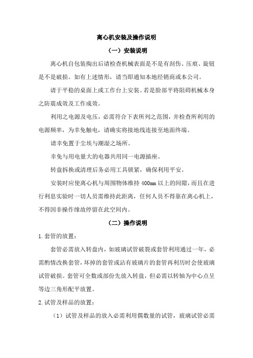
离心机安装及操作说明(一)安装说明离心机自包装掏出后请检查机械表面是不是有刮伤、压痕、旋钮是不是破损。
如有上述情形,请当即通知本地经销商或本公司。
请于平稳的桌面上或工作台上安装。
若是脸部平将阻碍机械本身之防震成效及工作成效。
利用之电源及电压,必需符合下表所列之范围,并检查所利用的电源频率,为幸免触电,请确实将接地线连接至地面终端。
请幸免置于尘埃与潮湿之场所。
幸免与用电量大的电器共用同一电源插座。
转盘拆换或清理后务必用工具锁紧,确保利用平安。
安装时应使离心机与周围物体维持400mm以上的间隙,而且在进行利息实验时一切人员需维持此距离,任何人员不得靠在离心机上,不得因非操作缘故停留在此空间内。
(二)操作说明1.套管的放置:套管必需放入转盘内,如玻璃试管破裂或套管利用通过一年,必需酌情改换套管,坏掉的套管或沾有玻璃片的套管再利历时会使玻璃试管破损。
套管可全数或部份先放入转盘,但必需以转轴为中心点呈等边三角形配平放置。
2.试管及样品的放置:(1)试管及样品的放入必需利用偶数量的试管,玻璃试管必需放入套管内,试管应呈等边三角形放置并以转轴为中心点(当利用不为三的倍数数量的试管时,要补试管装入同量的水充今世用品,严禁单管离心)。
(2)试管强度应考虑转速离心值得是不是可经受,不然易造成试管的破裂。
角度型转盘,如有试管较长,可距离放置,但仍不可太长利用。
3.门盖及门扣:采纳自动平安门扣方式,此为离心机的内锁系统:(1)门盖必需关紧,不然转盘无法旋转,运转时门盖无法开启。
(2)插入电源,开启主电源后,按下poen键及手动平安门扣,才能够打开门盖,不然无法打开盖。
(3)如遇停电无法打开门盖时,可用机身右边小孔,以长5公分以上圆棒水平插入并同时压手动平安门扣即可打开门盖。
4.机身分析图:(1)门盖(2)观测窗(3)手动平安门扣(4)插座及保险丝;于机身右后方(5)操作面板5.操作面牌说明:(1)运转键START: 将电源开关打开后,选择工况或从头设定好时刻及转速,按下此键,即可开始运转。
- 1、下载文档前请自行甄别文档内容的完整性,平台不提供额外的编辑、内容补充、找答案等附加服务。
- 2、"仅部分预览"的文档,不可在线预览部分如存在完整性等问题,可反馈申请退款(可完整预览的文档不适用该条件!)。
- 3、如文档侵犯您的权益,请联系客服反馈,我们会尽快为您处理(人工客服工作时间:9:00-18:30)。
Colleague 3 loading
0.按照一般set 排氣方式排氣
1.按下on/off 開關開機
PATIENT--->>>
2.按“channel select”選擇欲使 用的channel
3.按下“open”打開藍色閘門 A
4.channel 訊息顯示“Patient ” B
C
Colleague 3 loading
•最後按“start”開始輸注
Colleague 3 基本操作 (volume-time)
•完成SET安裝後, 按一下 “channel select”再按一下 “rate”鍵, 設定流速
•然後再按“volume”設定總流量
•或由上下鍵選擇欲更改的參 數
•最後按“start”開始輸注
Dose 計算操作
0.按照一般set 排氣方式排氣
1.按下on/off 開關開機
2.按“channel select”選擇欲使 用的channel 3.按下“open”打開藍色閘門
A 4.channel 訊息顯示“Patient ”
B 5.按照病人所在方向將藍色卡夾 C 放入藍色閘門,並將set 往後拉
1.將藍色卡夾關閉
Dose 計算操作
•利用上下鍵選擇並輸 入藥品重量, 溶液體積及
病人體重(如有計算體重時)
•所輸入體積會被當 作總流量
Dose 計算操作
•輸入所有參數後, 最後 按照醫囑輸入流速或 Dose機器會自動計算出 Dose 或流速
•必需選擇“confirm setting” 再按下“start” 即開始輸注
0.按照一般set 排氣方式排氣 1.按下on/off 開關開機 2.按“channel select”選擇欲使 用的channel
A B C
Colleague 3 loading
0.按照一般set 排氣方式排氣 1.按下on/off 開關開機 2.按“channel select”選擇欲使 用的channel 3.按下“open”打開藍色閘門
PATIENT--->>>
Loading
0. Set 按照一般set 排氣
1.按下on/off開關開機
2.按下open, 打開藍色 閘門 3.下方訊息顯示 “Patient ”
4.按照病人所在方向 將藍色卡夾放入藍色 閘門,並將set 往後拉
Loading
0. Set 按照一般set 排氣
1.按下on/off開關開機
B 5.按照病人所在方向將藍色卡夾 C 放入藍色閘門,並將set 往後拉 6.最後channel 訊息顯示“loading”,,,”stop”
Colleague 1基本操作 (volume-time)
•完成SET安裝後, 按一下“rate”鍵, 設定流速
•再按“volume”設定總流量
•或由上下鍵選擇欲 更改的參數
0. Set 按照一般set 排氣 1.按下on/off開關開機
Loading
0. Set 按照一般set 排氣 1.按下on/off開關開機 2.按下open, 打開藍色 閘門
Loading
0. Set 按照一般set 排氣 1.按下on/off開關開機 2.按下open, 打開藍色 閘門 3.下方訊息顯示 “Patient ”
2.將藍色卡夾放入 藍色閘門
3.握住set兩端往後輕 拉
Colleague 3 loading
0.按照一般set 排氣el select”選擇欲使 用的channel 3.按下“open”打開藍色閘門
A 4.channel 訊息顯示“Patient ”
Baxter IV pump 操作手冊
Colleague 1&3
Baxter IV pump 機型
• Colleague 1
• Colleague 3
Colleague 1外觀簡介
顯示/操作模組 幫浦模組
Colleague 1外觀簡介
跳回主螢幕 輸液量記錄 靜音
背景燈暗/亮
顯示螢幕 選 擇 鈕
Piggy back(兩種流速)
•按照基本操作或Dose 計算操作設定 “primary”流速及總流量 •之後選擇“Piggyback”
Piggy back(兩種流速)
•設定piggyback 流速及總流量(如基本操 作或Dose計算操作設定流速及流量)
數字鍵盤
流速 總量
開始 開關
Colleague 1外觀簡介
訊息顯示 閘門開啟鈕
暫停輸注鍵
藍色閘門
IV set 通道
Colleague 1外觀簡介
聲音調整鈕 備用保險絲
螢幕對比調整 面版鎖定鈕
電源線 手動釋放鈕
RS232
喇叭 固定夾
固定鈕
Colleague 3 外觀簡介
顯示/操作模組 幫浦模組
Colleague 3 外觀簡介
跳回主螢幕 輸液量記錄 靜音
背景燈暗/亮
顯示螢幕 選 擇 鈕
數字鍵盤
流速 總量
開始 開關
Colleague 3 外觀簡介
訊息顯示
Channel 選擇鈕
閘門開啟鈕
藍色閘門 Channel 選擇鈕
藍色閘門 Channel 選擇鈕
藍色閘門
暫停輸注鍵 暫停輸注鍵 暫停輸注鍵
IV set 通道
Colleague 3 外觀簡介
2.按下open, 打開藍色 閘門 3.下方訊息顯示 “Patient ”
4.按照病人所在方向 將藍色卡夾放入藍色 閘門,並將set 往後拉 5. 最後下方訊息顯 示“loading”
Colleague 3 loading
0.按照一般set 排氣方式排氣 1.按下on/off 開關開機
Colleague 3 loading
聲音調整鈕
螢幕對比調整
備用保險絲
面版鎖定鈕
電源線
RS232
喇叭
固定夾
手動釋放鈕
外接孔
操作簡介
• 上SET(Loading) • 基本操作(volume-time) • Dose 計算操作(mg/hr, mcg/hr,mg/kg/hr…) • Piggy back(兩種流速) • 設定藥名
Loading
完成set 安裝後下方選擇鍵 選擇“primary”
Dose 計算操作
•選擇“change mode”
Dose 計算操作
•利用“page up”或“page down” 選擇所需單位
•或利用上下鍵選擇所 需單位 •最後選擇“select”確認 •註:所使用單位可於裝 機時由工程師先設定好 常用單位就比較不會選 錯單位
