Ansys 12 Workbench 2中Fluent12练习教程
ansys fluent教程fluent12-lecture06-turbulence
Flux of energy
Dissipating eddies
Energy Cascade (after Richardson, 1922)
ANSYS, Inc. Proprietary © 2009 ANSYS, Inc. All rights reserved.
6-4
April 28, 2009 Inventory #002600
Turbulence Modeling
Introduction to Turbulence Modeling
Training Manual
• Characterization of Turbulent Flows • From Navier-Stokes Equations to Reynolds-Averaged Navier-Stokes (RANS) Models • Reynolds Stress Tensor and the Closure Problem • Turbulence Kinetic Energy (k) Equation • Eddy Viscosity Models (EVM) • Reynolds Stress Model • Near-wall Treatments Options and Mesh Requirement • Inlet Boundary Conditions • Summary: Turbulence Modeling Guidelines • Appendix
• Very sensitive to (or dependent on) initial conditions.
ANSYS, Inc. Proprietary © 2009 ANSYS, Inc. All rights reserved.
ansys 教程fluent12-lecture04-boundary-conditions

Training Manual
ANSYS, Inc. Proprietary © 2009 ANSYS, Inc. All rights reserved.
Combustor Wall
2. Nozzle inlet plane
• Non-premixed reaction models. • Requires accurate inlet profile. • Flow is still non-premixed.
2
3
3. 3 Nozzle outlet plane
• Velocity Inlet • Outflow (not recommended)
– Compressible
• Mass Flow Inlet • Pressure Far Field
• Cell (Continuum) zones
– Fluid – Solid – Porous media
ANSYS, Inc. Proprietary © 2009 ANSYS, Inc. All rights reserved.
4-5
April 28, 2009 Inventory #002600
Boundary Conditions
Locating Boundaries – An Example
Boundary Conditions
Porous Media
• A porous zone is a special type of fluid zone.
ansys12.0Workbench 教程

13.3.4 定义边界条件并求解
定义边界条件并求解包括在法兰面上施加固定约束、 定义边界条件并求解包括在法兰面上施加固定约束、 位移约束、施加压力和求解模型等内容。 位移约束、施加压力和求解模型等内容。 1.定义边界条件 . 2.求解模型 .
13.3.5 查看结果
图 球阀的应力等值线图
13.4
Workbench帮助资源 13.2.3 ANSYS 12.1 Workbench帮助资源
ANSYS 12.1 Workbench在启动时会自动弹出 在启动时会自动弹出Getting 在启动时会自动弹出 Started窗口,帮助使用者了解 窗口, 窗口 帮助使用者了解ANSYS Workbench的基本操 的基本操 其自带的英文帮助文档tutorials详尽介绍了软件的组织 作,其自带的英文帮助文档 详尽介绍了软件的组织 格式、使用方法和相关理论, 格式、使用方法和相关理论,并且提供了一些经典的例子供 用户学习。 用户学习。
13.4.4 定义边界条件并求解
定义边界条件并求解包括对叶根施加固定约束, 定义边界条件并求解包括对叶根施加固定约束,设置 最大模态阶数等边界条件和求解模型等内容。 最大模态阶数等边界条件和求解模型等内容。 1.定义边界条件 . 2.求解模型 .
13.4.5 查看结果
13.5
热力学分析实例
在第十二章热分析中已经介绍了热分析的基本概念、 在第十二章热分析中已经介绍了热分析的基本概念、 传热学经典理论、三种基本热传递方式等热分析基础知识、 传热学经典理论、三种基本热传递方式等热分析基础知识、 热分析的基本过程; 结构耦合分析 结构耦合分析、 应力耦合分析内 热分析的基本过程;热-结构耦合分析、热-应力耦合分析内 容和实例。 容和实例。热分析主要用于计算一个系统或部件的温度分布 及其它热物理参数,如热量的获取或损失、热梯度、 及其它热物理参数,如热量的获取或损失、热梯度、热流密 热通量) 度(热通量)等。ANSYS热分析基于能量守恒原理的热平 热分析基于能量守恒原理的热平 衡方程,用有限元法计算各节点的温度, 衡方程,用有限元法计算各节点的温度,并导出其它热物理 参数。 热分析包括热传导、 参数。 ANSYS热分析包括热传导、热对流及热辐射三种热 热分析包括热传导 传递方式。此外,还可以分析相变、有内热源、 传递方式。此外,还可以分析相变、有内热源、接触热阻等 问题。本节介绍如何使用ANSYS 12.1 Workbench对挡油环 问题。本节介绍如何使用 对挡油环 零件进行结构热分析。 零件进行结构热分析。
ansys fluent教程fluent12-lecture08-udf

8-5
April 28, 2009 Inventory #002600
User-Defined Functions
Fluent UDF Data Structure (2)
8-7
April 28, 2009 Inventory #002600
User-Defined Functions
Example – Parabolic Inlet Velocity Profile
Training Manual
• We would like to impose a parabolic inlet velocity to the 2D elbow shown.
Training Manual
– A UDF is a function (programmed by the user) written in C which can be dynamically linked with the FLUENT solver.
• Standard C functions
Segregated Userdefined ADJUST PBCS DBCS
Training Manual
Initialize
Begin Loop
Solver? Source terms
Solve U-Momentum
Source terms
Solve V-Momentum
Solve W-Momentum
Training Manual
Domain Thread cell_t face_t Node
ANSYSWorkbench12...

Workbench -Mechanical Introduction Introduction作业2.121ANSYS Mechanical基础2.1作业Supplement •第一个作业包含了大量的信息,练习时,可以更加的熟悉基本的Workbench Mechanical功能(菜单位置等),因此后续的作业就包含了较少的细节描述。
较少的细节描述•整个作业的菜单路径将被记录如下:“First pick > Second pick > etc.”.作业Supplement•使用Stress Wizard ,建立求解结构模型的应力、变形和安全因子。
问题描述•问题描述:–模型是由Parasolid 文件得到的一个控制箱盖子(如图所示)。
盖子假设是在一个外压下使用(1 Mpa/145 psi )。
–盖子是由铝合金制成的。
–我们的目标是确定这个部件能在假设的环境下使用。
作业Supplement •在深孔施加约束,接合面及内表面使用无摩擦支撑约束.–无摩擦支撑约束是一种施加在整个面的法无摩擦支撑约束是种施加在整个面的法线方向上的约束.除了支撑面的正、负法线方向, 该约束允许其余各方向的平移. 这是一种保守的方法.种保守的方法作业Supplement •载荷: 载荷为1MPa的压力,作用在外壳的17个外表面上.作业Supplement •打开Project page(项目页)•在Units菜单中确定:–Project 单位设为US Customary (lbm, in, s, F, A, lbf, V).–选择“Display Values in Project Units”作业Supplement1.在Toolbox 中建立一个StaticStructural 系统(通过拖放或点击鼠标右键选择)2.在Geometry 子模块上点击鼠标右键选择Import Geometry,选I G选择导入“Cap_fillets.x_t”文件作业Supplement3.双击Model 打开Mechanical application.4.当Mechanical application 打开模型时,会在图形窗中显示出来而窗口中显示出来,而Mechanical ApplicationWizard 会显示在右侧。
ansys fluent教程fluent12-lecture05-solver-settings

Yes Stop
5-3
April 28, 2009 Inventory #002600
Solver Settings
Available Solvers
ANSYSWorkbench12...

Workshop Supplement
July 14,2008 © 2007 ANSYS, Inc. All rights reserved.
Workbench-Simulation Heat Transfer ANSYS, Inc. Proprietary
Inventory #002557 WS1-13
Inventory #002557 WS1-6
材料
• 默认已经为模型选择了一个材料。 • 左击geometry项中的 “Solid”查看选 择的材料。 • 左击,高亮 “Material”然后左击选择 “edit structural steel”…
Workshop Supplement
July 14,2008 © 2007 ANSYS, Inc. All rights reserved.
Workbench-Simulation Heat Transfer ANSYS, Inc. Proprietary
Inventory #002557 WS1-16
检查求解
Workshop Supplement
• 查看是否和预计的一样,产生了一个热通量为固定值100 W/m2的区域。 • 查看X方向的热通量,是否和预计的一样,是一个很小的值。 • 注意要查看不同方向的结果时,我们必须选择其他方向,然后右击树中
方,然后点击“Evaluate All Results”。 – 任何添加的新条目都会立即看到,我们必须要求重新计算它们。
• 结果是–50 Watts。这在流入的热通量为100 watts/m2 以及杆的截面为1m x 0.5 m时成立。
Workshop Supplement
July 14,2008 © 2007 ANSYS, Inc. All rights reserved.
Fluent教程学习教程
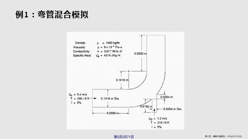
指定流体区域
第18页/共71页
第十八页,编辑于星期五:十九点 三十九分。
关闭DesignModeler
第19页/共71页
第十九页,编辑于星期五:十九点 三十九分。
第20页/共71页
第二十页,编辑于星期五:十九点 三十九分。
划分网格
第21页/共71页
第二十一页,编辑于星期五:十九点 三十九分 。
第34页/共71页
第三十四页,编辑于星期五:十九点 三十九分 。
第35页/共71页
第三十五页,编辑于星期五:十九点 三十九分 。
第36页/共71页
第三十六页,编辑于星期五:十九点 三十九分 。
启动Ansys Fluent
第37页/共71页
第三十七页,编辑于星期五:十九点 三十九分 。
第38页/共71页
第四十二页,编辑于星期五:十九点 三十九分 。
第43页/共71页
第四十三页,编辑于星期五:十九点 三十九分 。
第44页/共71页
第四十四页,编辑于星期五:十九点 三十九分 。
设置流体性质
第45页/共71页
第四十五页,编辑于星期五:十九点 三十九分 。
第46页/共71页
第四十六页,编辑于星期五:十九点 三十九分 。
第13页/共71页
第十三页,编辑于星期五:十九点 三十九分。
创建管道
第14页/共71页
第十四页,编辑于星期五:十九点 三十九分。
第15页/共71页
第十五页,编辑于星期五:十九点 三十九分。
第16页/共71页
第十六页,编辑于星期五:十九点 三十九分。
第17页/共71页
第十七页,编辑于星期五:十九点 三十九分。
第三十八页,编辑于星期五:十九点 三十九分 。
ansys12-FLUENT求解器设置
– SIMPLE-Consistent (SIMPLEC)
• 对简单问题,收敛更快,如层流
– Pressure-Implicit with Splitting of Operators (PISO)
• 对非稳态流动或者高扭曲度网格有用
– Fractional Step Method (FSM) 对非稳态问题
– 表现为残差曲线上扬(发散)或不下降 – 发散意味守恒方程的不平衡增加 – 没收敛的结果会误导使用者
解决方法 – 确保问题是物理合理的 – 用一阶离散格式计算一个初场 – 对压力基求解器,减少发散方程的 松弛因子 – 对密度基求解器,减少Courant 数 – 重新生成网格或加密质量差的网格
• 注意网格自适应不能提高扭曲度大 的网格质量
ANSYS FLUENT 培训教材 第四节:求解器设置
安世亚太科技(北京)有限公司
A Pera Global Company © PERA China
概要
使用求解器(求解过程概览) – 设置求解器参数 – 收敛 • 定义 • 监测
• 稳定性
• 加速收敛 – 精度 • 网格无关性 • 网格自适应 – 非稳态流模拟(后续章节中介绍) • 非稳态流问题设置
• 和 NITA 合用,类似 PISO.
A Pera Global Company © PERA China
初始化
FLUENT 要求所有的求解变 量有初始值 – 更真实的初值能提高收敛稳 定性,加速收敛过程. – 有些情况需要一个好的初值
在特定区域对特定变量单独 赋值 – 自由射流(喷射区高速) – 燃烧问题 (高温激活反应) – 单元标注(自适应)
No
Stop
与客户共同整理的FLUENT12经典培训教程——混合梯形管算例(周旋、高洁综合版本)

杨鹏
1.10, 2010 Inventory #002601
六面体网格划分步骤
Workshop Supplement
6、分割删除多余块 选择 Split Block -> Split Block,左击要分割的边,新的边垂直于选择的边, 左键拖动分割到合适的位置,中键或Apply 完成分割块操作。选择 Delete Block,选择要删除的块点击Apply 或中键完成删除块操作。
Workshop Supplement
• 四面体网格生成(带棱柱层)
– – – – – – – – – – 创建project项目文件,读入几何文件 拓朴检查几何完整性 创建parts,创建物质点 设置全局网格尺寸 设置面网格尺寸 设置线网格尺寸
设置密度盒(可以不设置)
在mesh中选compute mesh生成网格 设置生成边界层网格 导出
ANSYS, Inc. Proprietary © 2010 ANSYS, Inc.
杨鹏
1.10, 2010 Inventory #002601
六面体网格划分步骤
Workshop Supplement
12、输出到求解器 选择 Output > Select Solver,Output Solver 选择Fluent_V6; Common Structural Solver选择ANSYS 。选择 Write input,当提示保存是 ,选择 Yes,设置输出文件名称或是使用默认的名字选择 Done。
混合梯形管算例流程
(周旋、高洁综合版本)
ANSYS, Inc. Proprietary © 2009 ANSYS, Inc. All rights reserved.
ansys fluent教程fluent12-lecture07-heat-transfer

ANSYS, Inc. Proprietary © 2009 ANSYS, Inc. All rights reserved.
7-4
April 28, 2009 Inventory #002600
Heat Transfer Modeling
Wall Boundary Conditions
• Five thermal conditions
Heat Transfer Modeling
Outline
• Energy Equation • Wall Boundary Conditions • Conjugate Heat Transfer • Thin and two-sided walls • Natural Convection • Radiation Models • Reporting - Export
ANSYS, Inc. Proprietary © 2009 ANSYS, Inc. All rights reserved.
7-3
April 28, 2009 Inventory #002600
Heat Transfer Modeling
Energy Equation for Solid Regions
Chapter 7 Heat Transfer Modeling
Introductory FLUENT Training
ANSYS, Inc. Proprietary © 2009 ANSYS, Inc. All rights reserved.
7-1
April 28, 2009 Inventory #002600
Training Manual
– Heat Flux – Temperature – Convection – simulates an external convection environment which is not modeled (user-prescribed heat transfer coefficient). – Radiation – simulates an external radiation environment which is not modeled (user-prescribed external emissivity and radiation temperature). – Mixed – Combination of Convection and Radiation boundary conditions.
ANSYS_Workbench12.0培训教程
• 例子:
相邻体上共用节 点
3-8
General Preprocessing
… 材料属性
• 为体添加材料属性,从目录树中选取体,然后在 下拉菜单中选取 “Material”
– 新的材料数据可以在“Engineering Data”下添加 和输入。然后新的材料就可以从下拉菜单中得到。 – 对于 surface bodies,如上所讲,定义一个厚度 是必要的。
• 基本网格划分控制在“Mesh” 分支下的“Defaults” 中是可用的。
– 用户控制单个网格大小的选项
• “Relevance” 设置在 –100 与 +100之间
Training Manual
- Relevance = 粗划分
+ Relevance = 细划分
3-25
General Preprocessing
Training Manual
3-9
General Preprocessing
… 几何体表格
• 提供体素和已经定义的材料的总表
– 选择 “Geometry”分支和 “Worksheet”
Training Manual
3-10
General Preprocessing
B. 接触
• 存在多个部件时 ,需要确定部分之间的相互关系。
• 初始网格大小将由激活的部件(未抑制的)决定。
Training Manual
– Full Assembly(整个组件):
• 初始网格大小不会受部件的状态(抑制或活动)的影响。
– Parts(部件):
• 初始种子独立地建立在每个部件大小基础上,且网格不会因为部件受抑制而改变。一般给与一个 细化的网格。
AnsysFluent基础详细入门教程(附简单算例)
AnsysFluent基础详细⼊门教程(附简单算例)Ansys Fluent基础详细⼊门教程(附简单算例)当你决定使FLUENT解决某⼀问题时,⾸先要考虑如下⼏点问题:定义模型⽬标:从CFD模型中需要得到什么样的结果?从模型中需要得到什么样的精度;选择计算模型:你将如何隔绝所需要模拟的物理系统,计算区域的起点和终点是什么?在模型的边界处使⽤什么样的边界条件?⼆维问题还是三维问题?什么样的⽹格拓扑结构适合解决问题?物理模型的选取:⽆粘,层流还湍流?定常还是⾮定常?可压流还是不可压流?是否需要应⽤其它的物理模型?确定解的程序:问题可否简化?是否使⽤缺省的解的格式与参数值?采⽤哪种解格式可以加速收敛?使⽤多重⽹格计算机的内存是否够⽤?得到收敛解需要多久的时间?在使⽤CFD分析之前详细考虑这些问题,对你的模拟来说是很有意义的。
第01章fluent介绍及简单算例 (2)第02章fluent⽤户界⾯22 (3)第03章fluent⽂件的读写 (5)第04章fluent单位系统 (8)第05章fluent⽹格 (10)第06章fluent边界条件 (36)第07章fluent流体物性 (55)第08章fluent基本物理模型 (63)第11章传热模型 (75)第22章fluent 解算器的使⽤ (82)第01章fluent介绍及简单算例FLUENT是⽤于模拟具有复杂外形的流体流动以及热传导的计算机程序。
对于⼤梯度区域,如⾃由剪切层和边界层,为了⾮常准确的预测流动,⾃适应⽹格是⾮常有⽤的。
FLUENT解算器有如下模拟能⼒:●⽤⾮结构⾃适应⽹格模拟2D或者3D流场,它所使⽤的⾮结构⽹格主要有三⾓形/五边形、四边形/五边形,或者混合⽹格,其中混合⽹格有棱柱形和⾦字塔形。
(⼀致⽹格和悬挂节点⽹格都可以)●不可压或可压流动●定常状态或者过渡分析●⽆粘,层流和湍流●⽜顿流或者⾮⽜顿流●对流热传导,包括⾃然对流和强迫对流●耦合热传导和对流●辐射热传导模型●惯性(静⽌)坐标系⾮惯性(旋转)坐标系模型●多重运动参考框架,包括滑动⽹格界⾯和rotor/stator interaction modeling的混合界⾯●化学组分混合和反应,包括燃烧⼦模型和表⾯沉积反应模型●热,质量,动量,湍流和化学组分的控制体源●粒⼦,液滴和⽓泡的离散相的拉格朗⽇轨迹的计算,包括了和连续相的耦合●多孔流动●⼀维风扇/热交换模型●两相流,包括⽓⽳现象●复杂外形的⾃由表⾯流动上述各功能使得FLUENT具有⼴泛的应⽤,主要有以下⼏个⽅⾯●Process and process equipment applications●油/⽓能量的产⽣和环境应⽤●航天和涡轮机械的应⽤●汽车⼯业的应⽤●热交换应⽤●电⼦/HV AC/应⽤●材料处理应⽤●建筑设计和⽕灾研究总⽽⾔之,对于模拟复杂流场结构的不可压缩/可压缩流动来说,FLUENT是很理想的软件。
ANSYS12.0中Workbench模块高级使用技术
6
体和零件…
• Example:
– DM 中的一个多体零件, 有3个 实体.
DM
– DS 中也有3个 实体 (无接触).
– 每一个体网格是独立的,但体上的节点
在体之间是连续的。
DS
DM
H
7
布尔操作
• 可应用5 种布尔操作于3D 特征:
– Add Material : 生成材质并使模型与激活的体相融合。总是可用。
AWE高级培训教程
ANSYS进阶培训教程
之
Workbench高级使用技术
H
1
AWE高级培训教程 AWE建模高级技术
H
2
体和零件
• DesignModeler包括三个不同的体类型: – Solid body: 具有面积和体积的体。 – Surface body: 具有表面但无体积的体。 – Line body: 完全由线组成的体,无边、面积和体积。
线体 (无 截面)
H 在面的交界处上得到的连续有限元
26
网格
AWE高级培训教程 AWE高级分析高级技术
H
27
… 体素类型
• 实体体素 是指几何空间上的 3D的体: – 这些体可被划分成形函数为二次的高阶四面体单元或六面体单元。 – 每个节点对于结构有三个平动自由度,对于热分析有一个温度自由度。 – 能很好地显示CAD模型。
旋转轴 H
激活的草图
10
布尔操作…
• 布尔粘附面:
–粘附面 操作允许从连续的面分离出一个区域(见下面)。 例如考虑在任意位置应用有限元边界条件。
激活草图以拉伸之.
通过粘附面的操作拉伸.
H
11
布尔操作…
• 布尔添加冻结: – 类似于“加” 操作,但得到独立的体 (或单独的冻结体).
ANSYS Workbench12.0培训教程之简介
Workbench –Mechanical Introduction第一章简介B. ANSYS Workbench 简介Training Manual •什么是ANSYS Workbench?–ANSYS Workbench中提供了与ANSYS系统求解器的强大交互功能的方法。
这个环境提供了一个独特的CAD及设计过程的集成系统。
法这个环境提供了个独特的及设计过程的集成系统•ANSYS Workbench由多种的应用模块组成(例子):–Mechanical:利用ANSYS的求解器进行结构和热分析。
•网格划分也包含在Mechanical应用中。
–Mechanical APDL:采用传统的ANSYS用户界面对高级机械和多物理场进行分析。
–Fluid Flow (CFX):利用CFX进行CFD分析。
–Fluid Flow (FLUENT):使用FLUENT进行CFD分析。
Fl id Fl(FLUENT)–Geometry (DesignModeler):创建几何模型(DesignModeler)和CAD几何模型的修改。
Engineering Data:定义材料性能。
–Engineering Data–Meshing Application:用于生成CFD和显示动态网格。
–Design Exploration:优化分析。
()格行转–Finite Element Modeler (FE Modeler):对NASTRAN和ABAQUS的网格进行转化以进行ansys分析。
–BladeGen (Blade Geometry) :用于创建叶片几何模型。
–Explicit Dynamics:具有非线性动力学特色的模型用于显式动力学模拟。
Training Manual… ANSYS Workbench 简介•Workbench 环境支持两种类型的应用程序:–本地应用(workspaces):目前的本地应用包括工项目管理,工程数据和优化设计本机应用程序的启动完全在窗运行•本机应用程序的启动,完全在Workbench 窗口运行。
ansys fluent教程fluent12-lecture09-physics

Introductory FLUENT Training
ANSYS, Inc. Proprietary © 2009 ANSYS, Inc. All rights reserved.
9-1
April 28, 2009 Inventory #002600
1.1 mm
0.2 mm
ANSYS, Inc. Proprietary © 2009 ANSYS, Inc. All rights reserved.
Advanced Physics
Eulerian Model Example – 3D Bubble Column
Training Manual
z = 20 cm
– – – – – Eddy dissipation model Non-premixed, premixed and partially premixed combustion models Detailed chemistry models Pollutant formation Surface reactions
where
ANSYS, Inc. Proprietary © 2009 ANSYS, Inc. All rights reserved.
and
9-6
April 28, 2009 Inventory #002600
Advanced Physics
DPM Example – Spray Drier
Training Manual
– One of the phases is considered continuous (primary) – The others (secondary) are considered to be dispersed within the continuous phase. – There may be several secondary phase denoting particles of with different sizes.
ANSYS12.0_workbench教程
Introduction
Welcome!
Training Manual
• Welcome to the ANSYS Mechanical application introductory training course! • This training course covers the basics of using ANSYS Mechanical in performing structural and thermal analyses. • It is intended for all new or occasional ANSYS Mechanical users, regardless of the CAD software used. • Course Objectives:
1-4
February 23, 2009 Inventory #002593
Materials
• •
• • •
Training Manual
The Training Manual you have is an exact copy of the slides. Workshop descriptions and instructions are included in the Workshop Supplement. Copies of the workshop files are available on the ANSYS Customer Portal (). Advanced training courses are available on specific topics. Schedule available on the ANSYS web page / under “Solutions> Services and Support> Training Services”. Contents:
AnsysWorkbench详解教程全解
32
网格控制
整体网格 : Relevance (-100~100 ) 、 Relevance Center (coarse~ fine )
局部细化: 支撑处、载荷施加位置、应力变化较大的地方。
2020/1/12
33
网格控制
具体操作:选中结构树的Mesh项,点击鼠标右键,选择Insert,弹出 对网格进行控制的各分项,一般只需设置网格的形式(Method)和单元的 大小(Sizing)。
计算在固定不变的载荷作用下结构的响应,不考虑惯性和阻尼的影 响,如结构受随时间变化载荷的影响。
载荷——外部施加的作用力与压力; 稳态的惯性力(重力、离心力); 强迫位移;
温度载荷。
2020/1/12
36
4 选择分析类型
模态分析 (Modal ) :
用于确定结构或部件的振动特性,即结构的固有频率和振型 线性的、忽略系统阻尼对其自身振动特性的影响、任何所施加的力载荷
在模态分析中都不考虑。
*有预应力结构的模态分析:
先进行结构静力学分析,之后在模态分析初始条件(Initial Condition) 设置中指明结构预应力值来自前期静力分析结果。
2020/1/12
37
5 设置边界条件
边界条件的设置包括载荷和约束的施加,都作用在几何实体 上,通过节点和单元进行传递。
载荷和约束是在所选择的分析类型的分支(如模态分析、热分析 等),以下以静力分析为例进行说明。
2020/1/12
25
分析流程操作
初步确定
前处理 求解
后处理
分析类型:静力分析、模态分析 单元类型:壳单元、实体单元
模型类型:零件、组件 建立、导入几何模型
定义材料属性 划分网格
- 1、下载文档前请自行甄别文档内容的完整性,平台不提供额外的编辑、内容补充、找答案等附加服务。
- 2、"仅部分预览"的文档,不可在线预览部分如存在完整性等问题,可反馈申请退款(可完整预览的文档不适用该条件!)。
- 3、如文档侵犯您的权益,请联系客服反馈,我们会尽快为您处理(人工客服工作时间:9:00-18:30)。
Workshop Supplement
Leave all other defaults
– Click “OK” button to close Velocity Inlet panel
ANSYS, Inc. Proprietary 2008 ANSYS, Inc. All rights reserved. August 26, 2008 Inventory #002555
Drag the FLUENT Fluid Flow system from Standard Analyses group in the Toolbox onto preview drop target shown in the Project Schematic
– System name is highlighted – Type “Cylinder” and hit Enter – Geometry cell is flagged as Attention Required – Mesh and Setup cells are flagged as Refresh Required – Solution and Results cells are flagged as Unfulfilled
Save the project as “My_FLUENT_Project”
ANSYS, Inc. Proprietary 2008 ANSYS, Inc. All rights reserved.
WS1.2-9
August 26, 2008 Inventory #002555
Workshop 1.2
– Select Boundary Conditions under Problem Setup in navigation pane to access Boundary Conditions task page – Select velocity_inlet from Zones list and click on “Edit…” button
ANSYS, Inc. Proprietary 2008 ANSYS, Inc. All rights reserved.
Workshop Supplement
WS1.2-2
August 26, 2008 Inventory #002555
Workshop 1.2
Start Workbench
Select ANSYS Workbench 2 from the Start Menu Review message in “Getting Started” dialog, then close dialog by clicking the red X in the upper right-hand corner
Workshop Supplement
ANSYS, Inc. Proprietary 2008 ANSYS, Inc. All rights reserved.
WS1.2-3
August 26, 2008 Inventory #002555
Workshop 1.2
Create a FLUENT Fluid Flow System
Workshop Supplement
Create outlet boundary zone
– Left-click on the cylinder face located in negative z-direction to select it – Right-click and select “Create Named Selection” from pop-up menu – Name the selection, “pressure outlet”
Workshop 1.2
FLUENT 12 in Workbench 2 Overview
In this workshop, you will learn how to use FLUENT 12 in the new ANSYS Workbench 2 environment You will start by creating, solving and post-processing a simple FLUENT analysis Next, you will create two duplicate analyses, change the inlet velocity for the new analyses, update the project, and compare the results in CFD-Post
– Right-click on Mesh under Model in Outline and select Insert -> Method – Click on cylinder in Graphics window – In the Details view:
Click on “Apply” button that is next to Geometry under Scope to assign new meshing method to the cylinder Select Tetrahedrons for Method under Definition
August 26, 2008 Inventory #002555
Workshop 1.2
Generate a Mesh (1)
Right-click on Mesh cell A3 and select Edit
– Meshing opens and loads geometry
Workshop Supplement
Select Mesh under Model in Outline
– Note that Preferences are automatically set for FLUENT, based on system template
ANSYS, Inc. Proprietary 2008 ANSYS, Inc. All rights reserved.
Workshop 1.2
Workshop Supplement
Workshop 1.2 FLUENT 12 in Workbench 2
ANSYS, Inc. Proprietary 2008 ANSYS, Inc. All rights reserved.
WS1.2-1
August 26, 2008 Inventory #002555
ANSYS, Inc. Proprietary 2008 ANSYS, Inc. All rights reserved.
WS1.2-7
August 26, 2008 Inventory #002555
Workshop 1.2
Generate a Mesh (3)
Specify tetrahedral mesh method
ANSYS, Inc. Proprietary 2008 ANSYS, Inc. All rights reserved.
WS1.2-10
August 26, 2008 Inventory #002555
Workshop 1.2
Set-up FLUENT (2)
Specify inlet boundary condition
Workshop Supplement
在ANSYS12 WB2中从 Analysis Systems中拖放 Fluid Flow(Fluent)
ANSYS, Inc. Proprietary 2008 ANSYS, Inc. All rights reserved.
WS1.2-4
August 26, 2008 Inventory #002555
Workshop Supplement
Specify turbulence model
– Select Models under Problem Setup in navigation pane to access Models task page – Select Viscous-Laminar and click on “Edit…” button – Select k-epsilon under Model from Viscous Model panel and click “OK” button to close panel
WS1.2-6
August 26, 2008 Inventory #002555
Workshop 1.2
Generate a Mesh (2)
Create inlet boundary zone
– Left-click on the cylinder face located in positive z-direction to select it – Right-click and select “Create Named Selection” from pop-up menu – Name the selection, “velocity inlet”
Right-click on Mesh under Model in Outline and select Generate Mesh Close Meshing Review Project Schematic
– Mesh cell is Up-to-Date
Workshop Supplement
Set-up FLUENT (1)
Right-click on Setup cell A4 and select Edit
– Select “OK” button from FLUENT Launcher to accept defaults – FLUENT opens and loads the mesh
