RC4558DE4中文资料
45系列制动传感器产品数据手册说明书

Technical DataFork SensorsCatalog Numbers 45LSP-2LNA1-P3, 45LSP-2LPA1-P3, 45LSP-2LNA2-P3, 45LSP-2LPA2-P3, 45LSP-2LNA3-P3, 45LSP-2LPA3-P3, 45LSP-2LNA4-P3, 45LSP-2LPA4-P3, 45LST-1LEA1-P4, 45LST-1LEA2-P4, 45LST-1LEA3-P4, 45LST-1LEA4-P4, 45LST-1LEA5-P4, 45LST-1LEA6-P4, 45LST-1LEA7-P4Plastic Fork SensorsFeaturesThe 45LSP plastic fork sensors include the following features:•Detection of objects as small as 0.2 mm (0.08 in.)•Highly visible power and output LED indicators with output indication along both sides of the fork •Remote teach and teach button lock on 4-pin models•Selectable light or dark operate•Multiple mounting options: through-holes, threaded holes, and dovetail•Easy installation with no alignment required •IP67 rated enclosureTopicPagePlastic Fork Sensors 1Features 1Product Selection 2User Interface Panel 2Wiring Diagrams 2Approximate Dimensions3Optical and Response Time Characteristics 3Metal Fork Sensors 4Features 4Product Selection 4User Interface Panel 4Wiring Diagrams 4Dimensions5Optical and Response Time Characteristics 5Specifications6Fork SensorsTable 1 - Product Selection(1)Connection Options: The -P3 suffix describes a 3-pin pico (M8) integral QD. For additional connection options, replace the -P3 suffix with -P4: For a 4-pin pico (M8) integral QD connection (for example, 45LSP-2LPA1-P4). Table 2 - User Interface PanelWiring Diagrams* R emote teach2Rockwell Automation Publication FORK-TD001A-EN-P - May 2018Rockwell Automation Publication FORK-TD001A-EN-P - May 20183Fork SensorsApproximate Dimensions[mm (in.)]Optical and Response Time CharacteristicsGap Size (mm)A B C D E F G 3030 (1.18)50 (1.97)30 (1.18)34 (1.34)59.5 (2.34)20 (0.79)—5050 (1.97)70 (2.76)50 (1.97)54 (2.13)79.5 (3.13)20 (0.79)28 (1.10)8080 (3.15)100 (3.93)80 (3.15)54 (2.13)79.5 (3.13)20 (0.79) 2 x 28120120 (4.72)140 (5.51)120 (4.72)54 (2.13)79.5 (3.13)20 (0.79)3 x 28Characteristic 45LSP Plastic Fork 30 mm50 mm 80 mm 120 mm Resolution 0.2 mm (0.008 in.)0.4 mm (0.016 in.)Light Source Visible red LED 640 nmResponse Time0.25 ms4Rockwell Automation Publication FORK-TD001A-EN-P - May 2018Fork SensorsMetal Fork SensorsFeaturesThe 45LST Metal Fork Sensors include the following features:•Multi-turn sensitivity adjustment allows for high-precision adjustment •Fast 30 µs response time for selected models•NPN or PNP push-pull output helps streamline product inventory •Industrial aluminum housing •IP65 rated enclosureTable 3 - Product SelectionTable 4 - User Interface PanelWiring Diagrams*White wire not used.Rockwell Automation Publication FORK-TD001A-EN-P - May 20185Fork SensorsDimensions[mm (in.)]Optical and Response Time CharacteristicsAccessoriesA (Fork Size)BCD 2 (0.08)40 (1.57)14 (0.55) 6.25 (0.25)15 (0.59)40 (1.57)27 (1.06) 6.25 (0.25)30 (1.18)40 (1.57)42 (1.65) 6.25 (0.25)50 (1.97)57 (2.24)40 (1.57)17.25 (0.68)80 (3.15)57 (2.24)70 (2.75)17.25 (0.68)120 (4.72)57 (2.24)110 (4.33)17.25 (0.68)225 (8.86)60 (2.36)——Characteristic 45LST Metal Fork [mm (in.)]2 mm 15, 30, 50, 120, and 225 mm Resolution ——Light Source Infrared non-modulatedResponse Time0.03 ms 1 msDescriptionCatalog Number Pico style QD cordset, 3-pin889P-F3AB-2Dovetail Bracket used for Background and Foreground Suppression Sensors 44B44B-BKT6Rockwell Automation Publication FORK-TD001A-EN-P - May 2018Fork SensorsSpecificationsAdditional ResourcesThese documents contain additional information concerning related products from Rockwell Automation.Y ou can view or download publications at /global/literature-library/overview.page . T o order paper copies of technical documentation, contact your local Allen-Bradley distributor or Rockwell Automation sales representative.Attribute45LSP Plastic Fork 45LST Metal ForkCertifications c-UL-us Listed and CE Marked for all applicable directivesVibration 10…55 Hz, 1 mm (0.04 in.) amplitude, meets or exceeds IEC|600947-5-2Shock 30 g with 1 ms pulse duration, meets or exceeds IEC 600947-5-2 Environmental Enclosure type rating IP67IP65Operating temperature -10…+60 °C (14…140 °F)-20…+60 °C (-4…+140 °F)User Interface Sensitivity adjustment Push button 25-turn potentiometer Indicator LEDs Green and orange LEDs Green and red LEDsElectrical Operating voltage 10…30V DC Current consumption 30 mA40 mA maxProtection type Short circuit, reverse polarity, false pulse, overload Outputs Response time 0.25 ms1 ms, 0.03 ms (45LST-1LEA1-P4)Output type (1)(1)For Output Type and Connection Type, see Product Selection .Push-pull output (NPN or PNP)Output function Selectable light or dark operate Load current 100 mA Leakage current 0.5 mA max—Mechanical Housing material PolycarbonateAnodized aluminum Connection type(1)4-pin pico (M8) integral QDResourceDescriptionIndustrial Automation Wiring and Grounding Guidelines, publication 1770-4.1Provides general guidelines for installing a Rockwell Automation industrial system.Product Certifications website, /global/certification/overview.pageProvides declarations of conformity, certificates, and other certification details.Fork Sensors Notes:Rockwell Automation Publication FORK-TD001A-EN-P - May 20187Allen-Bradley, Rockwell Software, Rockwell Automation, and LISTEN. THINK. SOLVE are trademarks of Rockwell Automation, Inc.Trademarks not belonging to Rockwell Automation are property of their respective companies.Publication FORK-TD001A-EN-P - May 2018Copyright © 2018 Rockwell Automation, Inc. All rights reserved. Printed in the U.S.A.Rockwell Automation SupportUse the following resources to access support information.Documentation FeedbackY our comments will help us serve your documentation needs better. If you have any suggestions on how to improve this document, complete theHow Are W e Doing? form at /idc/groups/literature/documents/du/ra-du002_-en-e.pdf .Technical Support Center Knowledgebase Articles, How-to Videos, FAQs, Chat, User Forums, and Product Notification Updates./knowledgebaseLocal Technical Support Phone Numbers Locate the phone number for your country./global/support/get-support-now.pageDirect Dial Codes Find the Direct Dial Code for your product. Use the code to route your call directly to a technical support /global/support/direct-dial.page Literature Library Installation Instructions, Manuals, Brochures, and Technical Data./literatureProduct Compatibility and Download Center(PCDC)Get help determining how products interact, check features and capabilities, and find associated /global/support/pcdc.pageRockwell Otomasyon Ticaret A.Ş., Kar Plaza İş Merkezi E Blok Kat:6 34752 İçerenköy, İstanbul, T el: +90 (216) 5698400Rockwell Automation maintains current product environmental information on its website at /rockwellautomation/about-us/sustainability-ethics/product-environmental-compliance.page .Rockwell Automation SupportUse the following resources to access support information.Documentation FeedbackY our comments will help us serve your documentation needs better. If you have any suggestions on how to improve this document, complete the How Are W e Doing? form at /idc/groups/literature/documents/du/ra-du002_-en-e.pdf .Technical Support Center Knowledgebase Articles, How-to Videos, FAQs, Chat, User Forums, and Product Notification /knowledgebaseLocal Technical Support Phone Numbers Locate the phone number for your /global/support/get-support-now.page Direct Dial Codes Find the Direct Dial Code for your product. Use the code to route your call directly to a technical support /global/support/direct-dial.page Literature Library Installation Instructions, Manuals, Brochures, andTechnical /literature Product Compatibility and Download Center(PCDC)Get help determining how products interact, check features and capabilities, and find associated firmware./global/support/pcdc.pageWaste Electrical and Electronic Equipment (WEEE)At the end of life, this equipment can be collected separately from any unsorted municipal waste.。
UPC4558 中文PDF资料

UPC4558替换型号X4558 双极型线性集成电路
第一价值网(IC网络超市)
SIP-8-2.54
UNIT: mm
第一价值网(IC网络超市)
www.ic-jiazhi.com 7
UPC4558替换型号X4558 双极型线性集成电路
附:
第一价值网(IC网络超市)
典型工作参数曲线(接上表)
第一价值网(IC网络超市)
图 7 图图图图图图图图图图图图图图图
15.0
±15V
13.0
11.0
±12V
图 8 图图图图图图图图图图图图图图图
15.0
±15V
13.0
11.0
±12V
Output Voltage (peak) (V)
Output Voltage (peak) (V)
(仅一个通道)
符号
Vcc VI(DIFF)
VI TOPR TSTG
OUTPUT
输输 1 1 输输 1(-) 2 输输 1(+) 3
Vee 4
8 Vcc
7 输输 2 6 输输 2(-) 5 输输 2(+)
数值
±22 ±18 ±15 0—+70 -65—+150
单位
V V V ℃ ℃
第一价值网(IC网络超市)
3.5 2 5 30 ±12 3.5 20 ±14 ±13 70 76
5.6 6 200 500 ±13 5.6 200
mA mV nA nA V mA V/mV V
90
dB
90
dB
第一价值网(IC网络超市)
www.ic-jiazhi.com 3
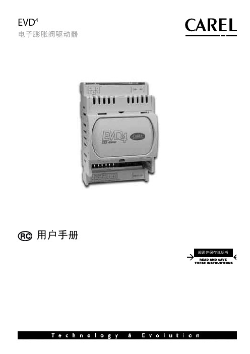
EVD4电子膨胀阀驱动器
3.5 通过RS485使用监控器(EVD000042*和EVD000045*). ............... 22
4. 技术和架构说明书 5. 故障排除 附录I 安装和使用EVD4-用户界面程序
24 25 26
I.I 安装........................................................ 26 I.II 准备连接. ................................................... 26 I.III 准备用户接口............................................... 26 I. IV 存储数据. ................................................... 26 I.V 载入数据. ................................................... 27 I. VI 修改参数. ................................................... 27 I.VII 有效配置. ................................................... 27
: 请参阅相应的说明书或参阅附录II“参数描述”中的“阀类型”参数 : 对于其它的传感器类型,请参阅第4章 “技术和架构特性”
EVD4 +03C220225 - rel. 1.1 - 16.11.2006
中文
1.2 连接到主串行口
EVD4 可以单独运行(独立模式),并连接到一台监控器来控制一些基本参数,或者 通过局域网与其它CAREL控制器连接到一起,可按以下示意图进行连接:
8XC54资料

272336 – 1
Figure 1 8XC5X Block Diagram
2
8XC52 54 58
PROCESS INFORMATION
This device is manufactured on P629 0 a CHMOS III-E process Additional process and reliability information is available in Intel’s Components Quality and Reliability Handbook Order No 210997
COPYRIGHT
INTEL CORPORATION 1996
March 1996
Order Number 272336-004
8XC52 54 58
Table 1 Proliferations Options Standard 1 80C32 80C52 87C52 80C54 87C54 80C58 87C58 X X X X X X X -1 X X X X X X X -2 X X X X X X X -24 X X X X X X X -33 X X X X X X X
PACKAGES
Part 8XC5X 87C5X 8XC5X 8XC5X Prefix P D N S Package Type 40-Pin Plastic DIP (OTP) 40-Pin CERDIP (EPROM) 44-Pin PLCC (OTP) 44-Pin QFP (OTP)
272336 – 3
PLCC
272336 –2
DIP
272336 – 4
Do not connect reserved pins
常用三极管参数大全

玉林万顺达电脑芯片级维修资料 2010-07-20整理玉林万顺达电脑芯片级维修资料 2010-07-20整理玉林万顺达电脑芯片级维修资料 2010-07-20整理玉林万顺达电脑芯片级维修资料 2010-07-20整理玉林万顺达电脑芯片级维修资料 2010-07-20整理玉林万顺达电脑芯片级维修资料 2010-07-20整理玉林万顺达电脑芯片级维修资料 2010-07-20整理玉林万顺达电脑芯片级维修资料 2010-07-20整理玉林万顺达电脑芯片级维修资料 2010-07-20整理玉林万顺达电脑芯片级维修资料 2010-07-20整理玉林万顺达电脑芯片级维修资料 2010-07-20整理玉林万顺达电脑芯片级维修资料 2010-07-20整理玉林万顺达电脑芯片级维修资料 2010-07-20整理玉林万顺达电脑芯片级维修资料 2010-07-20整理玉林万顺达电脑芯片级维修资料 2010-07-20整理玉林万顺达电脑芯片级维修资料 2010-07-20整理玉林万顺达电脑芯片级维修资料 2010-07-20整理玉林万顺达电脑芯片级维修资料 2010-07-20整理玉林万顺达电脑芯片级维修资料 2010-07-20整理玉林万顺达电脑芯片级维修资料 2010-07-20整理玉林万顺达电脑芯片级维修资料 2010-07-20整理玉林万顺达电脑芯片级维修资料 2010-07-20整理玉林万顺达电脑芯片级维修资料 2010-07-20整理玉林万顺达电脑芯片级维修资料 2010-07-20整理玉林万顺达电脑芯片级维修资料 2010-07-20整理玉林万顺达电脑芯片级维修资料 2010-07-20整理玉林万顺达电脑芯片级维修资料 2010-07-20整理玉林万顺达电脑芯片级维修资料 2010-07-20整理玉林万顺达电脑芯片级维修资料 2010-07-20整理玉林万顺达电脑芯片级维修资料 2010-07-20整理。
罗克韦尔自动化45CRM-4LHTx-D4颜色套传感器用户手册说明书
带 IO-Link 接口的颜色套准标记传感器
45CRM-4LHTx-D4
用户重要须知
在安装、配置、操作或维护设备之前,请仔细阅读本文档及 “ 其他资源” 部分列出的文档,了解设备的 安装、配置和操作信息。除所有适用规范、法规和标准的要求外,用户还应熟悉安装和接线说明。
安装、调整、投入使用、操作、组装、拆卸和维护等活动都应由经过适当培训的人员遵照适用的实施 规程执行。
注册 45CRM IODD . . . . . . . . . . . . . . . . . . . . . . . . . . . . . . . . . . . . . 36
检查 1734-4IOL IO-Link AOP. . . . . . . . . . . . . . . . . . . . . . . . . . . . 45
灼伤危险:位于设备 (例如,驱动器或电机) 表面或内部的标签,提醒人们表面可能存 在高温危险。 弧闪危险:标签可能位于设备上或设备内 (例如电机控制中心),提醒人们可能出 现弧闪。弧闪将造成严重的人身伤害或死亡。请穿戴适当的个人防护设备 (PPE)。遵循 所有安全工作惯例和个人防护设备 (PPE) 的规章要求。
目录
产品概述 . . . . . . . . . . . . . . . . . . . .. . . . . . . . 1
产品介绍 . . . . . . . . . . . . . . . . . . . . . . . . . . . . . . . . . . . . . . . . . . . . . . . . . . . . . . . . . . . . 1 工作模式 . . . . . . . . . . . . . . . . . . . . . . . . . . . . . . . . . . . . . . . . . . . . . . . . . . . . . . . . . . . . 1 特性. . . . . . . . . . . . . . . . . . . . . . . . . . . . . . . . . . . . . . . . . . . . . . . . . . . . . . . . . . . . . . . . . 2 技术参数 . . . . . . . . . . . . . . . . . . . . . . . . . . . . . . . . . . . . . . . . . . . . . . . . . . . . . . . . . . . . 3
W78E58B中文资料
8.3.1 时钟输入波形...................................................................................................................... 25 8.3.2 程序读取周期...................................................................................................................... 26 8.3.3 数据读取周期...................................................................................................................... 26 8.3.4 数据写周期.......................................................................................................................... 27 8.3.5 端口访问周期...................................................................................................................... 27
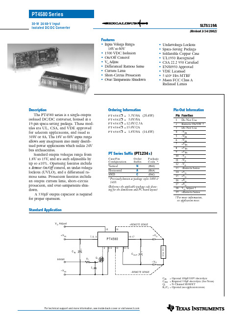
PT4584中文资料
Short Circuit Current Switching Frequency Under-Voltage Lockout
Remote On/Off Input (pin 2) Input High Voltage Input Low Voltage Input Low Current
元器件交易网 PT4580 Series
30-W 24/48-V Input Isolated DC/DC Converter
Features
• Input Voltage Range: 18V to 60V
• 1500 VDC Isolation • On/Off Control • Vo Adjust • Differential Remote Sense • Current Limit • Short-Circuit Protection • Over-Temperature Shutdown
PT Series Suffix (PT1234 x )
Case/Pin Configuration
Order Suffix
Package Code *
Vertical Horizontal
N
(END)
A
(ENA)
SMD
C
(ENC)
* Previously known as package styles 1400 & 1410.
(3) Output capacitor values are absolute. Allowances must be made for any additional de-coupling capacitors and the total external capacitor tolerance. The value of external capacitance is limited due to regulator startup current requirements. Consult the factory for further details.
RC4 中文操作手册
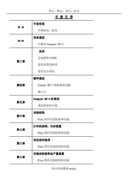
手册引导手册信息手册标识、版本设备描述什麽是Congrav RC-4总述总电源和24VDC使用电缆的种类使用安全须知硬件描述Conrav RC-4的机构和功能插入卡Congrav RC-4的调试调试和软件升级安装结构F1xx菜单页的机构和功能打印机结构,内存重置F2xx菜单页的机构和功能设定值和选项F3xx菜单页的机构和功能安装实际值和总产量重置F4xx菜单页的机构和功能单台加料器的操作Kxx1和Kxx2菜单页的机构和功能报警报告和开机条件Fxx5和Kxx5菜单页的机构和功能硬件结构数字输入输出的结构模拟输入输出的结构接口结构校正参数/附加参数F6xx菜单页的机构和功能硬件测试功能软件的测试功能和状态指示技术数据和零件清单模式显示清单菜单页清单内容提要1介绍1.1手册结构1.2补充文件1.3操作手册使用人群1.4手册中使用的信号和警示1.5使用的方式和缩写1.6版本附件2设备描述2.1目的2.2潜在的危险3总述3.1电源3.2外加24VDC3.3使用的电缆型号3.4安全须知3.4.1Congrav RC-4使用安全须知3.4.2安装安全须知3.4.3接线安全须知3.4.4使用和操作安全须知4硬件描述4.1Congrav RC-4:类型4.2Congrav RC-4A:显示和按键4.2.1集成按键及其功能4.2.2显示和功能组成4.3参数更改4.3.1数字输入4.3.2固定参数设置的选择4.3.3如果….,更改参数不被接受4.4Congrav RC-4B:4.5Congrav RC-4的插卡槽4.5.1现场的可能连线4.6Congrav RC-4的基本功能4.6.1插入卡RC4-MSIO4.6.1.1XS1.1:与主计算机的连接4.6.1.2XS1.2:与ISC现场总线的连接4.6.1.3XS1.3:与调试解调器和工控电脑的连接4.7Congrav RC-4的选项卡4.7.1CDIO插入卡4.7.2DIOP插入卡4.7.2.1输入输出模式-数字式RC-4的终端功能4.7.3ANOP插入卡4.7.3.1输入输出模式-模拟式RC-4的终端功能4.7.4Profibus模式5调试5.1安装5.2调试,Congrav RC-4的开机5.3Congrav RC-4:软件升级5.4ISC-CM:软件升级6菜单页F100安装结构6.1F110:安装模式6.2模拟结构6.3F120:主计算机操作6.4F130:显示内容改变6.5连锁停机6.6时间和日期6.7F150:配方处理6.7.1设定值斜线,设定值阈值6.7.2调试操作7F200:打印机结构,内存值重设7.1打印功能7.2F210:如何清除记忆内容8F300:设定值输入和选择8.1安装设定值8.2加料器设定值8.2.1`设定值的模拟控制8.2.2设定值斜线,设定值阈值(菜单页F150)8.3选项8.4F310:滞后时间8.5报警停机9F400:安装的实际值,总产量重设9.1F430:总产量重设10单台加料器操作10.1加料器页的抬头10.2Kxx0:加料器控制10.3操作功能10.3.1开机 5410.3.2停机 5410.3.3报警重设10.3.4补料 5510.3.5删除 5510.3.6开始试样10.3.7开始去皮10.3.8右侧行实际值的显示10.4Kxx1:产品参数10.4.1自动去皮10.4.2检查最大输出10.4.3堆积密度10.4.4体积最大输出10.4.5十进制转换10.4.5.1十进制转换的设置10.4.6模式 5910.4.6.1失重式加料(GF)10.4.6.2体积式控制(VR)10.4.6.3体积式设置(VS)10.4.6.4排料(DI)10.4.6.5检查最大输出(CM)10.4.6.6重量式排料(GD)10.4.6.7体积式加料(VF)10.4.6.8测量(M)10.4.6.9运行过程中GF和VF模式转换10.5Kxx2:控制参数10.5.1PID控制的设置10.5.1.1控制成套配合10.5.1.2重量式计算最大输出10.5.1.2.1CM值的存储11F500:报警报告和开机条件11.1报警报告11.2缺省的开机条件11.3系列驱动控制操作的错误代码11.3.1系列变频器11.3.2振动放大器控制器ISC-VC11.4Kxx5:报警结构12硬件结构12.1 Kxx8:ISC-CM(-A)的硬件结构12.1.1 速度输入12.1.2 传感器(重量读取)的结构12.1.3 驱动控制器12.1.4 ISC-CM-A模拟输入输出的结构12.1.4.1 ISC-CM-A上单台控制的选项12.1.4.2 Kxx8:模拟输入12.1.4.3 Kxx8:模拟输出12.2 ANOP模拟输入输出的结构12.2.1 安装控制和安装的实际值12.2.1.1 菜单页F190的参数12.2.2 ANOP的组分功能12.2.2.1 模拟输入:模拟单台控制12.2.2.2 模拟输出:总操纵量或实际值12.2.2.2.1 模拟输出信号范围的定义12.3 CDIO的数字输入输出12.4 DIOP的数字输入输出12.4.1 DIOP:功能描述12.5 ISC现场总线机构12.5.1 如果构建总线通讯12.5.2 总线通讯的关闭12.6 调试解调器的机构12.7 主计算机操作机构12.7.1 MISO卡上的主计算机接口12.7.2 Profibus DP操作结构12.7.3 以太网接口的结构13校正程序13.1加料器参数13.2加料器参数功能解释13.2.1CP02-加料范围13.2.2CP04-欠载13.2.3CP03-最大输出量13.2.4CP05-过载13.2.5CP06-粗去皮13.2.6CP07-平均重量取数13.2.7CP08-总产量累计分值13.2.8CP09-最小速度13.2.9CP010-最大速度13.2.10CP11-控制偏差13.2.11CP12-报警停机滞后时间13.2.12CP13-联锁类型13.2.13CP14-实际值指示13.2.14CP15-杠杆臂值13.2.15CP16-料斗内容13.2.16CP17-最小补料料位13.2.17CP18-最大补料料位13.2.18CP19-Window/K1/滤波IDL/F, AED 13.2.19CP20-数字速度13.2.19.1标准速度监控13.2.19.2FlexWall-Plus加料器的运动监控13.2.19.3数字式速度取数13.2.19.4推荐输入13.2.20CP21-最大补料时间13.2.21CP22-补料优化13.2.22CP23-稳定时间13.2.23CP24-测样时间13.2.24CP25-防振(AV)切断时间13.2.25CP26-PID控制器接近时间13.2.26CP27-控制器自动化13.2.26.1控制器自动化13.2.26.2开机自动化13.2.26.2.1重复的开机自动化13.2.26.2.2总体开机自动化13.2.27CP28-滤波限制13.2.28CP29-实际值的接纳13.2.29CP30-总操纵量的接纳13.2.30CP31-体积控制(VR)实际值的接纳13.2.31CP32-开机滞后时间13.2.32CP33-称重桥(LWB)的长度13.2.33CP34-重量测试值(WTV)13.2.34CP35-摄取(AP)13.2.35CP36-自动去皮范围13.2.36CP37-无负载时间自动去皮13.2.37CP38-有比例的皮带速度13.2.38CP39-皮带长度13.2.39CP40-dead time way13.3附加参数13.3.1AP01-05 校正13.3.2AP11-可用的称重范围13.3.3AP12-drop out13.3.4AP13-速度模式13.3.5AP14-滑动影响13.3.6AP15-滑动值13.3.7AP16-速度接纳性13.3.8AP17-无负载时间13.3.9AP18-AT时间13.3.10AP19-驱动控制2最小13.3.11AP20-驱动控制2最大14硬件测试功能14.1F140:输入输出测试-外围(安装)14.2Kxx3:输入输出状态显示-外围14.3Kxx4:测试功能和模拟14.3.1模拟模式14.3.2输入输出测试(加料器)15名词解释附件11915.1技术数据15.2电磁兼容性15.3零配件清单15.4可能显示的模式清单15.5菜单页清单插图表图4-1:Congrav RC-4后部视图图4-2:Congrav RC-4后部视图(带ProfiBus模式)1 总介绍1.1手册的结构现有的操作手册包括:RC-4的:技术操作和RC-4 HGC软件(其版本请参见封页)按照下列顺序,每章独立描述一个完整的主题:设备的描述使用特性硬件执行硬件功能定义操作软件描述参数描述和结构例举1.2附加文件ISC系统的描述ISC-CM,ISC-FC和ISC-VC的技术手册相应主计算机程序手册1.3操作手册所适用的人群操作手册适用于以下两组人群:经过授权和培训过的专业技术人员来进行安装和其它电气工作。
5804中文资料

5804中⽂资料Combining low-power CMOS logic with high-current and high-voltage bipolar outputs, the UCN5804B and UCN5804LB BiMOS II translator/drivers provide complete control and drive for a four-phase unipolar stepper-motor with continuous output current ratings to 1.25 A per phase (1.5 A startup) and 35 V.The CMOS logic section provides the sequencing logic, DIRECTION and OUTPUT ENABLE control, and a power-on reset function. Three stepper-motor drive formats, wave-drive (one-phase), two-phase, and half-step are externally selectable. The inputs are compatible with standard CMOS, PMOS, and NMOS circuits. TTL or LSTTL may require the use of appropriate pull-up resistors to ensure a proper input-logic high.The wave-drive format consists of energizing one motor phase at a time in an A-B-C-D (or D-C-B-A) sequence. This excitation mode consumes the least power and assures positional accuracy regardless of any winding inbalance in the motor. Two-phase drive energizes two adjacent phases in each detent position (AB-BC-CD-DA). This sequence mode offers animproved torque-speed product, greater detent torque, and is less susceptible to motor resonance. Half-step excitation alternates between the one-phase and two-phase modes (A-AB-B-BC-C-CD-D-DA), providing an eight-step sequence.The bipolar outputs are capable of sinking up to 1.5 A and withstanding 50 V in the off state (sustaining voltages up to 35 V). Ground-clamp and flyback diodes provide protection against inductive transients. Thermal protection circuitry disables the outputs when the chip temperature is exces-sive.Both devices are rated for operation over the temperature range of -20°C to +85°C. The UCN5804B is supplied in a 16-pin dual in-line plastic batwing package with a copper lead frame and heat-sinkable tabs for improved power dissipation capabilities; the UCN5804LB is supplied in a 16-lead plastic SOIC batwing package with a copper lead frame and heat-sinkable tabs.FEATURESI 1.5 A Maximum Output Current I 35 V Output Sustaining VoltageI Wave-Drive, Two-Phase, and Half-Step Drive Formats I Internal Clamp DiodesI Output Enable and Direction Control I Power-On ResetI Internal Thermal Shutdown CircuitryBiMOS II UNIPOLARSTEPPER-MOTOR TRANSLATOR/DRIVERAlways order by complete part number, e.g., UCN5804B .Data Sheet 26184.12C*5804115 Northeast Cutoff, Box 15036Worcester, Massachusetts 01615-0036 (508) 853-********BiMOS II UNIPOLAR STEPPER-MOTORTRANSLATOR/DRIVERTRUTH TABLEDrive Format Pin 9Pin 10Two-Phase L L One-Phase H L Half-Step L H Step-InhibitHHTYPICAL INPUT CIRCUITDwg. EP-021-4TYPICAL OUTPUT DRIVERDwg. EP-010-5INCopyright ? 1987, 2000 Allegro MicroSystems, Inc.5075100125150510A L L O W A B L E P A C K A G E P O W E R D I S S I P A T I O N I N W A T T STEMPERATURE IN °C43225Dwg. GP-049-2A5804BiMOS II UNIPOLAR STEPPER-MOTOR TRANSLATOR/DRIVER/doc/a3712eddb9f3f90f76c61b7c.htmlELECTRICAL CHARACTERISTICS at T A = 25°C, T J ≤ 150°C, V DD = 4.5 V to 5.5 V (unless otherwise noted). Limits CharacteristicSymbol Test Conditions Min.Typ.Max.Units Output Leakage Current I CEX V OUT = 50 V—1050µA Output Sustaining Voltage V CE(sus)I OUT = 1.25 A, L = 3 mH 35——V Output Saturation VoltageV CE(SAT)I OUT = 700 mA — 1.0 1.2V I OUT = 1 A — 1.1 1.4V I OUT= 1.25 A— 1.2 1.5V Clamp Diode Leakage Current I R V R = 50 V —1050µA Clamp Diode Forward Voltage V F I F = 1.25 A — 1.53.0V Input CurrentI IN(1)V IN = V DD —0.5 5.0µA I IN(0)V IN = 0.8 V —-0.5-5.0µA Input VoltageV IN(1)V DD = 5 V3.5— 5.3V V IN(0)-0.3—0.8V Supply Current I DD 2 Outputs ON—2030mA Turn-Off Delay t ON 50% Step Inputs to 50% Output ——10µs Turn-On Delayt OFF 50% Step Inputs to 50% Output ——10µs Thermal Shutdown TemperatureT J—165—°CTIMING CONDITIONSA. Minimum Data Set Up Time . . . . . . . . . . . . . . . . . . . . . . . . 100 nsB. Minimum Data Hold Time . . . . . . . . . . . . . . . . . . . . . . . . . . 100 nsC. Minimum Step Input Pulse Width . . . . . . . . . . . . . . . . . . . . . 3.0 µsDwg. W-110AONE PHASE HALF STEPOOUTPUT ENABLEOUTPUT C OUTPUT DCLOCK115 Northeast Cutoff, Box 15036Worcester, Massachusetts 01615-0036 (508) 853-50005804BiMOS II UNIPOLAR STEPPER-MOTORTRANSLATOR/DRIVERWAVE-DRIVE SEQUENCEHalf Step = L, One Phase = H Step A B C D POR ON OFF OFF OFF 1ON OFF OFF OFF 2OFF ON OFF OFF 3OFF OFF ON OFF 4OFFOFFOFFONTWO-PHASE DRIVE SEQUENCEHalf Step = L, One Phase = LStep A B C D POR ON OFF OFF ON 1ON OFF OFF ON 2ON ON OFF OFF 3OFF ON ON OFF 4OFFOFFONONHALF-STEP DRIVE SEQUENCEHalf Step = H, One Phase = LStep A B C D POR ON OFF OFF OFF 1ON OFF OFF OFF 2ON ON OFF OFF 3OFF ON OFF OFF 4OFF ON ON OFF 5OFF OFF ON OFF 6OFF OFF ON ON 7OFF OFF OFF ON 8ONOFFOFFONAPPLICATIONS INFORMATIONInternal power-on reset (POR) circuitry resets OUTPUT A (and OUTPUT D in the two-phase drive format) to the on state with initial applica-tion of the logic supply voltage. After reset, the circuit then steps according to the tables.The outputs will advance one sequenceposition on the high-to-low transition of the STEP INPUT pulse. Logic levels on the HALF-STEP and ONE-PHASE inputs will determine the drive format (one-phase, two-phase, or half-step). The DIRECTION pin determines the rotation se-quence of the outputs. Note that the STEP INPUT must be in the low state when changing the state of ONE-PHASE, HALF-STEP, or DIRECTION to prevent erroneous stepping.All outputs are disabled (off) when OUTPUT ENABLE is at a logic high. If the function is not required, OUTPUT ENABLE should be tied low.In that condition, all outputs depend only on the state of the step logic.During normal commutation of a unipolar stepper motor, mutual coupling between the motor windings can force the outputs of the UCN5804B below ground. This condition will cause forward biasing of the collector-to-substrate junction and source current from the output. For many L/R applications, this substrate current is high enough to adversely affect the logic circuitry and cause misstepping. External series diodes (Schottky are recommended for increasedefficiency at low-voltage operation) will prevent substrate current from being sourced through the outputs. Alternatively, external ground clamp diodes will provide a preferred current path from ground when the outputs are pulled below ground.Internal thermal protection circuitry disables all outputs when the junction temperature reaches approximately 165°C. The outputs are enabled again when the junction cools down to approxi-mately 145°C.5804BiMOS II UNIPOLAR STEPPER-MOTOR TRANSLATOR/DRIVER/doc/a3712eddb9f3f90f76c61b7c.htmlTYPICAL APPLICATION L/R Stepper-Motor DriveThe products described here are manufactured under one or more U.S. patents or U.S. patents pending.Allegro MicroSystems, Inc. reserves the right to make, from time to time, such departures from the detail specifications as may berequired to permit improvements in the performance, reliability, or manufacturability of its products. Before placing an order, the user is cautioned to verify that the information being relied upon is current.Allegro products are not authorized for use as critical components in life-support devices or systems without express written approval.The information included herein is believed to be accurate and reliable. However, Allegro MicroSystems, Inc. assumes no responsi-bility for its use; nor for any infringement of patents or other rights of third parties which may result from its use.115 Northeast Cutoff, Box 15036Worcester, Massachusetts 01615-0036 (508) 853-50005804BiMOS II UNIPOLAR STEPPER-MOTORTRANSLATOR/DRIVERUCN5804BDimensions in Inches (controlling dimensions)Dimensions in Millimeters(for reference only)NOTES:1.Exact body and lead configuration at vendor’s option within limits shown.2.Lead spacing tolerance is non-cumulative.3.Lead thickness is measured at seating plane or below.4.Webbed lead frame. Leads 4, 5, 12, and 13 are internally one piece.5.Supplied in standard sticks/tubes of 25 devices.Dwg. MA-001-17A in18Dwg. MA-001-17A mm185804 BiMOS II UNIPOLAR STEPPER-MOTOR TRANSLATOR/DRIVER/doc/a3712eddb9f3f90f76c61b7c.htmlUCN5804LB(add “TR” to part number for tape and reel) Dimensions in Inches(for reference only)Dimensions in Millimeters(controlling dimensions)NOTES:1.Exact body and lead configuration at vendor’s option within limits shown.2.Lead spacing tolerance is non-cumulative.3.Lead thickness is measured at seating plane or below.4.Webbed lead frame. Leads 4, 5, 12, and 13 are internally one piece.5.Supplied in standard sticks/tubes of 47 devices or add “TR” to part number for tape and reel.115 Northeast Cutoff, Box 15036Worcester, Massachusetts 01615-0036 (508) 853-50005804BiMOS II UNIPOLAR STEPPER-MOTORTRANSLATOR/DRIVERMOTOR DRIVERSFunctionOutput Ratings*Part Number ?INTEGRATED CIRCUITS FOR BRUSHLESS DC MOTORS3-Phase Power MOSFET Controller —28 V 39333-Phase Power MOSFET Controller —50 V 39323-Phase Power MOSFET Controller —50 V 76002-Phase Hall-Effect Sensor/Driver 400 mA 26 V 3626Bidirectional 3-Phase Back-EMFController/Driver ±600 mA 14 V 89062-Phase Hall-Effect Sensor/Driver 900 mA 14 V 36253-Phase Back-EMFController/Driver ±900 mA 14 V 8902–A 3-Phase Controller/Drivers ±2.0 A 45 V 2936 & 2936-120INTEGRATED BRIDGE DRIVERS FOR DC AND BIPOLAR STEPPER MOTORSDual Full Bridge with Protection & Diagnostics ±500 mA 30 V 3976PWM Current-Controlled Dual Full Bridge ±650 mA 30 V 3966PWM Current-Controlled Dual Full Bridge ±650 mA 30 V 3968PWM Current-Controlled Dual Full Bridge ±750 mA 45 V 2916PWM Current-Controlled Dual Full Bridge ±750 mA 45 V 2919PWM Current-Controlled Dual Full Bridge ±750 mA 45 V 6219PWM Current-Controlled Dual Full Bridge ±800 mA 33 V 3964PWM Current-Controlled Full Bridge ±1.3 A 50 V3953PWM Current-Controlled Dual Full Bridge ±1.5 A 45 V 2917PWM Current-Controlled Microstepping Full Bridge ±1.5 A 50 V 3955PWM Current-Controlled Microstepping Full Bridge ±1.5 A 50 V 3957PWM Current-Controlled Dual DMOS Full Bridge ±1.5 A 50 V 3972Dual Full-Bridge Driver ±2.0 A 50 V 2998PWM Current-Controlled Full Bridge ±2.0 A 50 V3952DMOS Full Bridge PWM Driver ±2.0 A 50 V 3958Dual DMOS Full Bridge ±2.5 A 50 V 3971UNIPOLAR STEPPER MOTOR & OTHER DRIVERSVoice-Coil Motor Driver ±500 mA 6 V 8932–A Voice-Coil Motor Driver ±800 mA 16 V 8958Unipolar Stepper-Motor Quad Drivers 1 A 46 V 7024 & 7029Unipolar Microstepper-Motor Quad Driver 1.2 A 46 V 7042Unipolar Stepper-Motor Translator/Driver 1.25 A 50 V 5804Unipolar Stepper-Motor Quad Driver 1.8 A 50 V 2540Unipolar Stepper-Motor Quad Driver 1.8 A 50 V 2544Unipolar Stepper-Motor Quad Driver 3 A 46 V 7026Unipolar Microstepper-Motor Quad Driver 3 A 46 V 7044*Current is maximum specified test condition, voltage is maximum rating. See specification for sustaining voltage limits or over-current protection voltage limits. Negative current is defined as coming out of (sourcing) the output.?Complete part number includes additional characters to indicate operating temperature range and package style.Also, see 3175, 3177, 3235, and 3275 Hall-effect sensors for use with brushless dc motors.。
RC4558中文资料
PACKAGING INFORMATIONOrderable Device Status(1)PackageType PackageDrawingPins PackageQtyEco Plan(2)Lead/Ball Finish MSL Peak Temp(3)RC4558D ACTIVE SOIC D875Pb-Free(RoHS)CU NIPDAU Level-2-260C-1YEAR/Level-1-235C-UNLIMRC4558DGKR ACTIVE MSOP DGK82500Green(RoHS&no Sb/Br)CU NIPDAU Level-2-260C-1YEARRC4558DR ACTIVE SOIC D82500Green(RoHS&no Sb/Br)CU NIPDAU Level-1-260C-UNLIMRC4558ID ACTIVE SOIC D875Pb-Free(RoHS)CU NIPDAU Level-2-260C-1YEAR/Level-1-235C-UNLIMRC4558IDGKR ACTIVE MSOP DGK82500Green(RoHS&no Sb/Br)CU NIPDAU Level-2-260C-1YEARRC4558IDR ACTIVE SOIC D82500Green(RoHS&no Sb/Br)CU NIPDAU Level-1-260C-UNLIMRC4558IP ACTIVE PDIP P850Pb-Free(RoHS)CU NIPDAU Level-NC-NC-NCRC4558IPW ACTIVE TSSOP PW8150Pb-Free(RoHS)CU NIPDAU Level-1-250C-UNLIMRC4558IPWR ACTIVE TSSOP PW82000Pb-Free(RoHS)CU NIPDAU Level-1-250C-UNLIMRC4558P ACTIVE PDIP P850Pb-Free(RoHS)CU NIPDAU Level-NC-NC-NCRC4558PSLE OBSOLETE SO PS8None Call TI Call TIRC4558PSR ACTIVE SO PS82000Pb-Free(RoHS)CU NIPDAU Level-2-260C-1YEAR/Level-1-235C-UNLIMRC4558PW ACTIVE TSSOP PW8150Pb-Free(RoHS)CU NIPDAU Level-1-250C-UNLIM RC4558PWLE OBSOLETE TSSOP PW8None Call TI Call TIRC4558PWR ACTIVE TSSOP PW82000Pb-Free(RoHS)CU NIPDAU Level-1-250C-UNLIM RC4558Y OBSOLETE XCEPT Y0None Call TI Call TI(1)The marketing status values are defined as follows:ACTIVE:Product device recommended for new designs.LIFEBUY:TI has announced that the device will be discontinued,and a lifetime-buy period is in effect.NRND:Not recommended for new designs.Device is in production to support existing customers,but TI does not recommend using this part in a new design.PREVIEW:Device has been announced but is not in production.Samples may or may not be available.OBSOLETE:TI has discontinued the production of the device.(2)Eco Plan-May not be currently available-please check /productcontent for the latest availability information and additional product content details.None:Not yet available Lead(Pb-Free).Pb-Free(RoHS):TI's terms"Lead-Free"or"Pb-Free"mean semiconductor products that are compatible with the current RoHS requirements for all6substances,including the requirement that lead not exceed0.1%by weight in homogeneous materials.Where designed to be soldered at high temperatures,TI Pb-Free products are suitable for use in specified lead-free processes.Green(RoHS&no Sb/Br):TI defines"Green"to mean"Pb-Free"and in addition,uses package materials that do not contain halogens, including bromine(Br)or antimony(Sb)above0.1%of total product weight.(3)MSL,Peak Temp.--The Moisture Sensitivity Level rating according to the JEDECindustry standard classifications,and peak solder temperature.Important Information and Disclaimer:The information provided on this page represents TI's knowledge and belief as of the date that it is provided.TI bases its knowledge and belief on information provided by third parties,and makes no representation or warranty as to theaccuracy of such information.Efforts are underway to better integrate information from third parties.TI has taken and continues to take reasonable steps to provide representative and accurate information but may not have conducted destructive testing or chemical analysis on incoming materials and chemicals.TI and TI suppliers consider certain information to be proprietary,and thus CAS numbers and other limited information may not be available for release.In no event shall TI's liability arising out of such information exceed the total purchase price of the TI part(s)at issue in this document sold by TI to Customer on an annual basis.元器件交易网IMPORTANT NOTICETexas Instruments Incorporated and its subsidiaries (TI) reserve the right to make corrections, modifications,enhancements, improvements, and other changes to its products and services at any time and to discontinueany product or service without notice. Customers should obtain the latest relevant information before placingorders and should verify that such information is current and complete. All products are sold subject to TI’s termsand conditions of sale supplied at the time of order acknowledgment.TI warrants performance of its hardware products to the specifications applicable at the time of sale inaccordance with TI’s standard warranty. T esting and other quality control techniques are used to the extent TIdeems necessary to support this warranty. Except where mandated by government requirements, testing of allparameters of each product is not necessarily performed.TI assumes no liability for applications assistance or customer product design. Customers are responsible fortheir products and applications using TI components. T o minimize the risks associated with customer productsand applications, customers should provide adequate design and operating safeguards.TI does not warrant or represent that any license, either express or implied, is granted under any TI patent right,copyright, mask work right, or other TI intellectual property right relating to any combination, machine, or processin which TI products or services are used. Information published by TI regarding third-party products or servicesdoes not constitute a license from TI to use such products or services or a warranty or endorsement thereof.Use of such information may require a license from a third party under the patents or other intellectual propertyof the third party, or a license from TI under the patents or other intellectual property of TI.Reproduction of information in TI data books or data sheets is permissible only if reproduction is withoutalteration and is accompanied by all associated warranties, conditions, limitations, and notices. Reproductionof this information with alteration is an unfair and deceptive business practice. TI is not responsible or liable forsuch altered documentation.Resale of TI products or services with statements different from or beyond the parameters stated by TI for thatproduct or service voids all express and any implied warranties for the associated TI product or service andis an unfair and deceptive business practice. TI is not responsible or liable for any such statements.Following are URLs where you can obtain information on other Texas Instruments products and applicationsolutions:Products ApplicationsAmplifiers Audio /audioData Converters Automotive /automotiveDSP Broadband /broadbandInterface Digital Control /digitalcontrolLogic Military /militaryPower Mgmt Optical Networking /opticalnetworkMicrocontrollers Security /securityTelephony /telephonyVideo & Imaging /videoWireless /wirelessMailing Address:Texas InstrumentsPost Office Box 655303 Dallas, Texas 75265Copyright 2005, Texas Instruments Incorporated。
J1.5-3.5UT 4轮电动叉车产品介绍说明书

J1.5-3.5UT 4-WHEEL ELECTRIC FORKLIFT2HIGH STRENGTH OVERHEAD GUARDThe overhead guard features profiled steel, with high strength materials to help enhance reliability and operator protection.2LOW STEP HEIGHTThe conveniently positioned lo w step provides easy access to the t ruck.3AC CONTROLLERAC controllers coupled with AC traction and hydraulic motors allow for precise truck controllability. The controllers are easily accessible which can also minimize service time.The Hyster ® UT series provides the ideal solution to meet your needs, without compromising on performance.OVERVIEW1243THE RANGE1,500kg – J1.5UT 1,800kg – J1.8UT 2,000kg – J2.0UTDESIGNThe design of the UT series has been engineered with the operator in mind. The ergonomically designed compartment provides a natural and comfortable environment to help reduce fatiguethroughout the shift. A range of standard features and options help to configure the truck to the needs of the application.2,500kg – J2.5UT 3,000kg – J3.0UT 3,500kg – J3.5UT36WIDE VIEW MASTThe wide view mast provides the operator with a significant front field of view, minimizing blind spots and increasing operator comfort, thereby enabling safe, productive and efficient operation.4SMALL STEERING WHEELThe adjustable steering wheel position provides convenience for the operator as it provides 8degrees of adjustment. Low steering effort makes it easy to operate in confined spaces.5INTEGRATED MOTOR, TRANSMISSION AND AXLEThe compact structure of the drive system provides adequate access for maintenance. Precision cut gears are incorporated, leading to reduced wear and lower noise levels.65LOW COST OF OWNERSHIPThe use of high quality and robust components contribute to reliableoperations and lower wear and tear. This, together with fast availability of cost-effective replacement parts helps to reduce maintenance requirements and costs.HYDRAULICSHigh quality cylinders with hard chrome rods reduce seal wear for long life. A full-flow, low pressure filter on the return line keeps the hydraulic oil clean, which helps to minimize seal and pump wear. In addition, this keeps the control valve in good condition, which can lead to low service costs.4ENGINEERED FOR OPERATORSSAFETY AND STABILITY• High visibility mast with soft landing absorbs shock• Controlled mast lowering speed helps reduce damaging product• Secure overhead guard • LED lights are standard • Operator presence system • Travel speed limiting • Parking brakeCOMFORT• Hydraulic power steering requires low steering effort without kick-back which helps with precise positioning• Full suspension seat• Adjustable steering column and seat to accommodate a variety of operators • Low entrance step and large floor space • Ergonomically designed hand brakePERFORMANCE• Simple and clear display of speed, power,error code, working hours to keep the operator informed• Color display integrated with functions such as performance selection allows the operator to configure the truck to meet different application requirements• AC traction and lifting motors, with electronic control, deliver a high level of performanceSERVICE• AC traction and hydraulic motors help reduce maintenance cost • Reliable IP54 design• The controller assembly is mounted inside the counterweight and is protected by an easy-to-remove cover• CANbus communication simplifies troubleshooting5Mast TypeMax fork height(mm)Overall Extended HeightFree lift Mast Tilt Capacity without side shift Lowered height (mm)Lift heightWithout LBR (mm)With LBR (mm)Forward (Deg)Back (Deg)@ 500mm Single Pneumatic Tire (kg)@ 600mm Single PneumaticTire (kg)Without LBR (mm)With LBR (mm)1.5t1.8t 1.5t 1.8t 1.5t 1.8t 1.5t 1.8t 1.5t 1.8t 2LFL3300214021404284428438133813135135510150018001350162035002240224044844484401340131351355101500180013501620400025402540498449844513451313513551014001700126015322FFL300019901990398439843513351314151030510150018001350162033002140214042844284381338131565118051015001800135016203FFL450020402040548454845013501314701080561200140010801260480021402140578457845313531315701180561100120099010805500240524056484648460136013183514453675085067076060002590261069846984651365132040165036450550400490J1.5-1.8UT MAST AND CAPACITY CHARTSMast TypeMax fork height(mm)Overall Extended HeightFree lift Mast Tilt Capacity without side shift Lowered height (mm)Lift heightWithout LBR (mm)With LBR (mm)Forward (Deg)Back (Deg)@ 500mm Single Pneumatic Tire (kg)@ 600mm Single PneumaticTire (kg)Without LBR (mm)With LBR (mm)2.0t2.5t 2.0t 2.5t 2.0t 2.5t 2.0t 2.5t 2.0t 2.5t 2LFL3300216521653915391543174317140140510200025001810226035002265226541154115451745171401405102000250018102260400025652565461546155017501714014051020002500181022602FFL30002015201536153615401740171385985510200025001810226033002165216539153915431743171535113551020002500181022603FFL450020752075517151715516551614401040561600200014501810480021752175547154715816581615401140561250170011301540550024402440617161716516651618001400369001200810109060002625262566716671701670161990159036700800630720J2.0-2.5UT MAST AND CAPACITY CHARTSMast TypeMax fork height(mm)Overall Extended HeightFree lift Mast Tilt Capacity without side shift Lowered height (mm)Lift heightWithout LBR (mm)With LBR (mm)Forward (Deg)Back (Deg)@ 500mm Single Pneumatic Tire (kg)@ 600mm Single PneumaticTire (kg)Without LBR (mm)With LBR (mm)3.0t3.0t3.0t 3.0t 3.0t 2LFL3300219539404440165165510300027203500229541404640165165510300027204000259546405140165165510285025802FFL3000204536404140139093551030002720330021953940444015401085510300027203FFL450020955165564015109755625002270480021955465594016101075562250204055002460616566401865133036160014506000264566657140206015253612001090J3.0UT MAST AND CAPACITY CHARTSMast TypeMax fork height(mm)Overall Extended HeightFree lift Mast Tilt Capacity without side shift Lowered height (mm)Lift heightWithout LBR (mm)With LBR (mm)Forward (Deg)Back (Deg)@ 500mm Single Pneumatic Tire (kg)@ 600mm Single PneumaticTire (kg)Without LBR (mm)With LBR (mm)3.5t3.5t3.5t 3.5t 3.5t 2LFL3300227040104440170170510350031803500237042104640170170510350031804000267047105140170170510330030002FFL30002120370041001415100051035003180330022704000440015651150510350031803FFL450021705250565015109755628002550480022705550595016101075562500227055002535625066501865133036170015406000272067507150206015253613001180J3.5UT MAST AND CAPACITY CHARTSNote: For integral sideshift deduct 50kg from stated capacityMAST SPECIFICATIONS6SPECIFICATIONSG E N E R A L1.1Manufacturer HYSTER HYSTER HYSTER HYSTER HYSTER HYSTER 1.2Model designationJ1.5UT J1.8UT J2.0UT J2.5UT J3.0UT J3.5UT 1.3Power: battery, diesel, LPG, electric mainsBatería Batería Batería Batería Batería Batería 1.4Operation: manual, pedestrian, stand, seat, orderpicker Sentado Sentado Sentado Sentado Sentado Sentado 1.5Load capacity Q (kg)1500180020002500300035001.6Load center c (mm)5005005005005005001.8Load distance x (mm)410410454454475495 51.9Wheelbasey (mm)138013801485148516701690W E I G H T 2.1Unladen weight (max. battery)kg 2950323039304100475054002.2Axle loading, laden front/rear (max. battery)kg 3960/4904280/6105160/7505755/8456900/8507865/10352.3Axle loading, unladen front/rear (max. battery)kg1390/15601290/18001895/20351650/24502070/26802300/3100T I R E S , C H A S S I S 3.1Tires: L=pneumatic, V=cushion SE= super elastic SE SE SE SE SE SE 3.2Tire size, front 6.00-921x8-923 x 9-1023 x 9-1023 x 9-1023 x 10-123.3Tire size, rear5.00-8 5.00-818 x 7-818 x 7-818 x 7-8200/50-103.5Number of wheels, front/rear (X = driven)2x/22x/22x/22x/22x/22x/23.6Track width, front b10 (mm)95595510581058106511243.7Track width, rear b11 (mm)9209209609609801010D I M E N S I O N S 4.1Mast tilt, forward a /back b degrees 5/105/105/105/105/105/104.2Height of mast, lowered h1 (mm)2000200020152015204521204.3Free lift, "h2 (mm)1351351401401651654.4Lift height, "h3 (mm)3000300030003000300030004.5Height of mast, extended E h4 (mm)3980398039803980398039804.7Height to top of overhead guard m h6 (mm)2155215521522152215221384.8Seat height u h7 (mm)1080108010801080108010804.12Towing coupling height h10 (mm)2902902502502702704.19Overall length (with forks)l1 (mm)2993 29933356 5 3356 5 3618 3709 4.20Length to face of forks l2 (mm)207320732286.52286.5254826394.21Overall width b1 (mm)1120112012851285128513654.22Fork dimensionss/e/l (mm)35/100/92035/100/92040/122/107040/122/107045/122/107050/122/10704.23Fork carriage DIN 15173. Class, A/B 2A 2A 2A 2A 3A 3A 4.24Fork carriage width E b3 (mm)1040104010401040110011004.25Width over forksb5 (mm)89089010001000106010604.31Ground clearance, laden, below mast m1 (mm)9595656565804.32Ground clearance at center of wheelbasem2 (mm)1051059595110834.33Aisle width with pallets 1000mm long x 1200mm wide Ast (mm)3541354137323732402541014.34Aisle width with pallets 800mm wide x 1200mm long Ast (mm)3741374139323932422543014.35Outer turning radius Wa (mm)1965196520802080234924054.36Inner turning radius b13 (mm)703703599599830815P E R F O R M A N C E D A T A 5.1Travel speed laden/unladen km/h 15/1615/1615/1615/1615/1615/165.2Lifting speed laden/unladen mm/s 320/400300/400320/400280/400320/400280/4005.3Lowering speed laden/unladenmm/s 390/500390/500390/420390/420390/420400/3205.6Maximum drawbar pull laden/unladen, 5 minute rating N 11600/750011600/750013000/1050013000/1050019000/1100019000/110005.8Maximum gradeability with/without load, 5 minute rating %15/2314/2215/2315/2215/2215/225.9Acceleration time with/without load 10m sec 5/4.55/4.5 5.4/4.5 5.5/4.7 5.5/4.7 5.7/5.25.10Service brakeHidráulico Hidráulico Hidráulico Hidráulico Hidráulico Hidráulico E L E C T R I C -M O T O R 6.1Drive Motor Rating, S2, 60min kW 6.5 6.58.58.511.511.56.2Lifting motor, S3 15% rating kW 8.68.6111115156.4Battery voltage/capacity (5hr rate)V/Ah 48/42048/42048/60048/60080/50080/5006.5Battery weight (min/max)kg 71071095095014201420NEW Battery dimensionsl/w/h(mm)985/465/750985/465/7501028/500/7801028/500/7801028/674/7801028/674/7806.6Power consumption in accordance with VDI cycle kWh/h 4.8 5.0 5.7 6.27.68.0O T H E R 8.1Drive control CA CA CA CA CA CA ManufacturerCurtis Curtis Curtis Curtis Curtis Curtis 8.2Operating pressure for attachments x bar 1451451751751751758.3Oil volume for attachments l/min 3838383838388.4Average noise level at operator's ear ¬dB (A)70.370.367.567.571.871.88.5Towing coupling, type DINClavija de Ø30Clavija de Ø30Clavija de Ø30Clavija de Ø30Clavija de Ø30Clavija de Ø30¬ L PAZ, measured according to the test cycles and based on the weighting values contained in EN12053“ Bottom of forksu Full suspension specified E Without load backrestm h6 subject to +/- 5 mm tolerance x VariableSpecification data is based on VDI 2198, with the following configuration: Complete truck with 3000mm 2-stage limited free lift mast, standard carriage and forks, overhead guard and standard super elastic drive and steer tires.7DIMENSIONS100 mm100 mm4.14.54.44.24.34.22 4.311.8 4.191.194.204.324.124.84.74.14.224.344.334.21 3.74.354.223.64.217807307152X 670690116116334414102868320501101457807307003X 67565653344141028503205080111ModelCompartment sizeBattery specifications Electrical Battery size WeightW mm (in)L mm (in)H mm (in)Voltage W mm (in)L mm (in)H mm (in)Min kg (lbs)Max kg (lbs)J1.5-1.8UT Vertical extract 993 (39.0)478 (18.8)785 (30.9)48980 (38.6)465 (18.3)750 (29.5)650 (1435)790 (1740)J2.0-2.5UT Vertical extract 1041 (40.9)500 (19.6)785 (30.9)481028 (40.4)500 (19.6)780 (30.7)855 (1885)1045 (2300)J3.0-3.5UT Vertical extract1041 (40.9)674 (26.5)785 (30.9)801028 (40.4)674 (26.5)780 (30.7)1280 (2825)1560 (3435)Battery type: “EO” (without cover)Battery compartment length is measured front to rear. Battery compartment width is measured across the truck Battery lead: length 250mm (10”), bosition “B”, 2 / 0 AWGBATTERY COMPARTMENT SPECIFICATIONSHyster Company P .O. Box 7006Greenville, North Carolina 27835-7006Part No. J1.5-3.5UT/BTG/CARIB 8/2020 Litho in U.S.A.Visit us online at or call us at 1-800-HYSTER-1.Hyster, and STRONG PARTNERS, TOUGH TRUCKS, are registered trademarks in the United States and certain other jurisdictions. Hyster products are subject to change without notice.Trucks may be shown with optional equipment. © 2020 Hyster Company. All rights reserved.J1.5-1.8UT7506809804682X 702X 139J2.0-2.5UTJ3.0-3.5UT。
FESTO 卫生式蝴蝶阀 VZFB 产品概述说明书
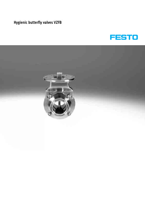
Hygienic butterfly valves VZFBProduct range overview2è Internet: /catalog/...Subject to change – 2016/03Type codesVZFB–A–1–C C–V4V4E TypeVZFB Hygienic butterfly valvesBased on standardA ASME BPED DIN 11851SZ SMS 1145Size111½1½222½2½334425DN2540DN4050DN5065DN6580DN80100DN100Connection type 1C ClampW Welded endT ThreadConnection type 2C ClampW Welded endT ThreadBodyV4Stainless steel 1.4404V2Stainless steel 1.4301Connecting componentV4Stainless steel 1.4404V2Stainless steel 1.4301SealsE EPDMV FPMè Internet: /catalog/...2016/03 – Subject to change3Subject to change – 2016/034è Internet: /catalog/...Technical dataGeneral Technical dataDesign2-way hygienic butterfly valve Sealing principle Soft Actuation type Manual Mounting position AnyType of mounting In-line installation Direction of flowReversibleSuitability for use in the food industry As per manufacturer's declarationOperating and environmental conditions Nominal pressure PN 10MediumWaterNeutral fluidsTemperature of medium1)VZFB-…-…-…-…E [°C]–10 … 120VZFB-…-…-…-…V [°C]–15 … 140Corrosion resistance VZFB-…-…-…-…-V2V2CRC 2)3VZFB-…-…-…-…-V4V4CRC 3)41)The pressure diagram must be observed. The permissible temperature is dependent on the pressure range.2)Corrosion resistance class 3 according to Festo standard 940 070Components subject to high corrosion stress. External visible parts in direct contact with industrial atmospheres or media such as solvents and cleaning agents, with a predominantly functional requirement for the surface.3)Corrosion resistance class 4 to Festo standard 940 070Components subject to particularly high corrosion stress. Parts used with aggressive media, e.g. in the food or chemical industry. These applications should be supported with special tests with the media if required.Permissible operating pressure p as a function of the temperature of the medium tEPDM FPMMaterialsInformation on materials Material numberHousing, washer, shaft VZFB-…-…-…-…-V2V2High-alloy stainless steel1.4301VZFB-…-…-…-…-V4V4 1.4404Note on materialsFree of copper and PTFE, RoHS-compliant, contains PWIS (paint-wetting impairment substances)Technical dataType D∅D1∅D2∅H1±0.5H2±0.5L1±1L2ß1VZFB-A-1-WW-...22.47825.449.4950208 VZFB-A-1½-WW-...35.18638.153.3950208 VZFB-A-2-WW-...47.810250.862.510522210 VZFB-A-2½-WW-...59.511563.56910562210 VZFB-A-3-WW-...72.212876.275.510562210 VZFB-A-4-WW-...97.6154101.690.311642211 VZFB-D-25-WW- (26782849950208)VZFB-D-40-WW-…38904055.6950208 VZFB-D-50-WW-…501065264.310522210 VZFB-D-65-WW-…661247073.710562210 VZFB-D-80-WW-…811398581.611602211 VZFB-D-100-WW-…10015910491.8116422112016/03 – Subject to change5è Internet: /catalog/...Technical dataType D∅D1∅D2∅H1±0.5H2±0.5L1±1L2ß1VZFB-A-1-CC-…22.47850.549.4966208 VZFB-A-1½-CC-…35.18650.553.3970208 VZFB-A-2-CC-…47.81026462.510762210 VZFB-A-2½-CC-…59.511577.56910802210 VZFB-A-3-CC-…72.21289175.510842210 VZFB-A-4-CC-…97.615411990.3111042211Subject to change – 2016/03 6è Internet: /catalog/...Technical dataType D∅D1∅D2∅H1±0.5H2±0.5L1±1L2ß1VZFB-SZ-1-…22.478Rd 40x1/649.4966208 VZFB-SZ-1½-…35.186Rd 60x1/653.3970208 VZFB-SZ-2-…47.8102Rd 70x1/662.510762210 VZFB-SZ-2½-…59.5115Rd 85x1/66910802210 VZFB-SZ-3-…72.2128Rd 98x1/675.510842210 VZFB-SZ-4-…97.6154Rd 125x1/490.31110422112016/03 – Subject to change7è Internet: /catalog/...Technical data8è Internet: /catalog/...Subject to change – 2016/03Technical dataè Internet: /catalog/...2016/03 – Subject to change9Accessories10è Internet: /catalog/...Subject to change – 2016/03AccessoriesType Valve size Drive B1D1D2D3D4D5DIN∅∅∅∅∅DARQ-K-25-F0405-S11-S-R1DN 25Single 5.283.5504296DN 25Double 5.283.5504296DN 40Double 5.283.5504296 DARQ-K-50-F0405-S11-D-R1DN 50Double583.5504296 DARQ-K-65-F0405-S14-S-R1DN 65Single583.5504296–Single583.5504296 DARQ-K-65-F0405-S11-D-R1DN 65Double583.5504296–Double583.5504296 DARQ-K-80-F0405-S11-D-R1DN 80Double583.5504296 DARQ-K-80-F0405-S14-S-R1DN 80Single583.5504296DN 100Double583.5504296 DARQ-K-100-F0405-S17-S-R1DN 100Single583.5504296Type D6H1H2H3H4H5L1ß1∅DINDARQ-K-25-F0405-S11-S-R1768673911467.811768673911467.811774.6673911467.811 DARQ-K-50-F0405-S11-D-R1782.3803911567.811 DARQ-K-65-F0405-S14-S-R1791.7864315567.8147–864315567.814 DARQ-K-65-F0405-S11-D-R1791.7863911567.8117–863911567.811 DARQ-K-80-F0405-S11-D-R1798.6933911567.811 DARQ-K-80-F0405-S14-S-R1798.6934315567.8147108.8934315567.814 DARQ-K-100-F0405-S17-S-R17108.81104618567.817è Internet: /catalog/...2016/03 – Subject to change11AccessoriesMounting kit DARQ Information on materials: Array Mounting, coupling:High-alloy stainless steelNote on materials:Contains PWIS (paint-wetting impairment substances), RoHS-compliant,free of copper and PTFE1)CRC3: Corrosion resistance class to Festo standard 940 070Components with heavy corrosion exposure. Externally visible components in direct contact with normal industrial atmosphere or media such as solvents and cleaning agents, where the surface requirement is predominantly functional.12è Internet: /catalog/...Subject to change – 2016/03AccessoriesHand lever VAOH Information on materials: Array High-alloy stainless steelNote on materials:Contains PWIS (paint-wetting impairment substances), RoHS-compliant,free of copper and PTFE1)CRC3: Corrosion resistance class to Festo standard 940 070Components with heavy corrosion exposure. Externally visible components in direct contact with normal industrial atmosphere or media such as solvents and cleaning agents, where the surface requirement is predominantly functional.è Internet: /catalog/...2016/03 – Subject to change13Festo - Your Partner in AutomationConnect with us/socialmedia 1Festo Inc.2Festo Pneumatic 3Festo Corporation 4Regional Service Center 5300 Explorer DriveMississauga, ON L4W 5G4CanadaAv. Ceylán 3,Col. Tequesquináhuac 54020 Tlalnepantla, Estado de México1377 Motor Parkway Suite 310Islandia, NY 117497777 Columbia Road Mason, OH 45040Festo Customer Interaction CenterTel:187****3786Fax:187****3786Email:*****************************Multinational Contact Center 01 800 337 8669***********************Festo Customer Interaction Center180****3786180****3786*****************************S u b j e c t t o c h a n g e。
745058-4资料
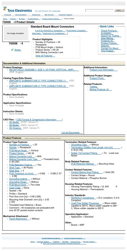
745058-4 Product DetailsHome | Customer Support | Suppliers | Site Map | Privacy Policy | Browser Support© 2007 Tyco Electronics Corporation All Rights Reserved SearchHome > Products > By Type > D Subminiature > Product Feature Selector > Product DetailsNo Image Available745058-4Active Standard Board Mount Connectors5 of6 EU RoHS/ELV Compliant (Find RoHS CompliantAlternates/Statement of Compliance)Product Highlights:?Number of Positions = 25?Receptacle?PCB Mount Angle = Vertical?Product Series = HD 20?With Mating Connector LockView all FeaturesCheck Pricing &AvailabilitySearch for ToolingView MatingProducts (4)Product FeatureSelectorContact Us AboutThis ProductQuick LinksDocumentation & Additional InformationProduct Drawings:?RECEPTACLE ASSEMBLY, SIZE 3, 25 POSN, VERTICAL, AMPL...(PDF, English)Catalog Pages/Data Sheets:?AMPLIMITE SUBMINATURE D TYPE CONNECTORS (1)(PDF,English)?AMPLIMITE SUBMINATURE D TYPE CONNECTORS (2)(PDF,English)Product Specifications:?None AvailableApplication Specifications:?None AvailableInstruction Sheets:?None AvailableCAD Files: (CAD Format & Compression Information)?3D Model(STEP, Version F)?3D Model(IGES, Version F)?2D Drawing(DXF, Version F)List all Documents Additional Information:?Product Line InformationAdditional Product Images: ?Product PhotoRelated Products:?Tooling?Mating Products (4)Product Features (Please use the Product Drawing for all design activity)Product Type Features:?Number of Positions = 25?Gender = Receptacle?PCB Mount Angle = Vertical?Product Series = HD 20?Mating Connector Lock = With?Mating Connector Lock Type = Threaded Insert,4-40 UNC?PCB Retention Feature = Yes?Shell Type = All Plastic?Shell Size = 3?PCB Thickness (in [mm]) = 0.062 –0.093 [1.57– 2.36]?Grounding Indents = Without?Grounding Straps = Without?PCB Mount Style = Thru Hole?Color Code = None?Sealed = No?Profile = Standard?Post Size (mm [in]) = 0.66 [.026]?Mounting Hole Diameter (mm [in]) = 3.05[.120]?Threaded Insert Material = Brass?Comment = All receptacles are preloaded withsize 20 DF posted socket contactsMechanical Attachment:?Panel Attachment = Without Termination Related Features:?Grounding Clips = Without?Termination (Solder) Post Length (mm [in]) =3.18 [0.125]?Solder Tail Contact Plating = Tin-Lead overNickelBody Related Features:?PCB Retention Method = Mounting Holes Contact Related Features:?Contact Mating Area Plating = Gold (30)?Contact Shape = Round?Contact Material = Phosphor BronzeHousing Related Features:?Housing Flammability Rating = UL 94V-0?Housing Material = ThermoplasticIndustry Standards:?RoHS/ELV Compliance = ELV compliant, 5 of 6Compliant?Lead Free Solder Processes = Wave soldercapable to 240°C, Wave solder capable to 260°C, Wave solder capable to 265°COperation/Application:?Application = StandardOther:?Brand = AMPProvide Website Feedback | Contact Customer Support Products Documentation Resources My Account Customer Support。
RC4558中文详细资料
2
MΩ
Output Resistance输出电阻
Ro
75
Ω
Total Harmonic Distortion总谐波失真
THD
f=1KHz, Av=20dB, RL=2kΩ, Vo=2Vpp, CL=100pF
0.008
%
单位增益带宽
BW
2
2.8
MHZ
CMRR
Rs≤10kΩ
70
90
dB
Supply Voltage Rejection Ratio电源电压抑制比
PSRR
Rs≤10kΩ
76
90
dB
Output Voltage swing输出电压摆幅
Vo(p-p)
RL≥10kΩ
±12
±14
V
Power Consumption功耗
Pc
70
170
mV
Slew Rate摆率
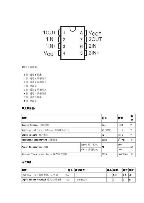
4558引脚功能:
1脚通道1输出
2脚通道1反相输入
3脚通道1同相输入
4脚电源负
5脚通道2同相输入
6脚通道2反相输出
7脚通道2输出
8脚电源正
最大额定值:
参数
符号
数值
ቤተ መጻሕፍቲ ባይዱ单位
Supply Voltage电源电压
Vcc
±22
V
Differential Input Voltage差分输入电压
VI(DIFF)
±18
SR
Vi=±10V, RL≥2kΩ, CL≤100pF
1.2
2.2
V/μS
Rise Time上升时间
TRIS
Vi=±20mV, RL≥2kΩ, CL≤100pF
Festo MFH-5-1 8-S-B电压阀说明书
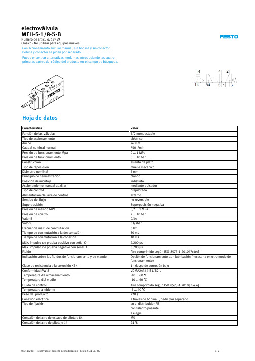
electroválvula MFH-5-1/8-S-B
Número de artículo: 19759 Clásico - No utilizar para equipos nuevos
Con accionamiento auxiliar manual, sin bobina y sin conector. Bobina y conector se piden por separado.
Conexión del aire de escape de pilotaje 84 Conexión del aire de pilotaje 14
Valor
5/2 monoestable eléctrico 26 mm 750 l/min 0 ... 1 MPa 0 ... 10 bar asiento de plato muelle mecánico 5 mm blando indistinto mediante pulsador prepilotado externo no reversible Superposición negativa 0,2 ... 1 MPa 2 ... 10 bar 0,34 3 l/sbar 3 Hz 30 ms 10 ms 2.200 µs 3.700 µs Aire comprimido según ISO 8573-1:2010 [7:4:4] Opción de funcionamiento con lubricación (necesaria en otro modo de funcionamiento)
SMC VS#8-(2,4) 5口式气体阀门说明书

tester in the axial direction and at the right angles to the main valve and
armature in both energized and de-energized states every once for each
condition. (Values quoted are for a new valve).
Vibration resistance: No malfunction occurred in a one-sweep test between
8.3 and 2000 Hz. Test was performed at both energized states in the axial
direction and at the right angles to the main valve and armature. (Values
Flow characteristics
Response time [ms]
Duty cycle
Minimum operating frequency
Maximum operating frequency
Manual override
Impact / vibration resistance [m/s2] Note 2) Lubrication
2.3 Manifold specifications
Series
1(P), 3(R)
Port size
2(A), 4(B)
12(PE), 14(X)
Electrical entry
VS#8-2 (VV802) VS#8-4 (VV801) Enclosure
- 1、下载文档前请自行甄别文档内容的完整性,平台不提供额外的编辑、内容补充、找答案等附加服务。
- 2、"仅部分预览"的文档,不可在线预览部分如存在完整性等问题,可反馈申请退款(可完整预览的文档不适用该条件!)。
- 3、如文档侵犯您的权益,请联系客服反馈,我们会尽快为您处理(人工客服工作时间:9:00-18:30)。
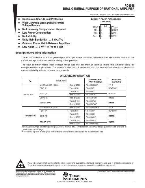
SLOS073E – MARCH 1976 – REVISED FEBRUARY 2006
FEATURES
• • • • • • • • Continuous Short-Circuit Protection Wide Common-Mode and Differential Voltage Ranges No Frequency Compensation Required Low Power Consumption No Latch-Up Unity-Gain Bandwidth . . . 3 MHz Typ Gain and Phase Match Between Amplifiers Low Noise . . . 8 nV/√Hz Typ at 1 kHz
Please be aware that an important notice concerning availability, standard warranty, and use in critical applications of Texas Instruments semiconductor products and disclaimers thereto appears at the end of this data sheet.
Package drawings, standard packing quantities, thermal data, symbolization, and PCB design guidelines are available at /sc/package. The actual top-side marking has one additional character that designates the assembly/test site.
Copyright © 1976–2006, Texas Instruments Incorporated
元器件交易网 RC4558 DUAL GENERAL-PURPOSE OPERATIONAL AMPLIFIER
SLOS073E – MARCH 1976 – REVISED FEBRUARY 2006
Stresses beyond those listed under Absolute Maximum Ratings may cause permanent damage to the device. These are stress ratings only, and functional operation of the device at these or any other conditions beyond those indicated under Recommended Operating Conditions is not implied. Exposure to absolute-maximum-rated conditions for extended periods may affect device reliability. All voltage values, unless otherwise noted, are with respect to the midpoint between VCC+ and VCC–. Differential voltages are at IN+ with respect to IN–. The magnitude of the input voltage must never exceed the magnitude of the supply voltage or 15 V, whichever is less. Temperature and/or supply voltages must be limited to ensure that the dissipation rating is not exceeded. Maximum power dissipation is a function of TJ (max), θJA, and TA. The maximum allowable power dissipation at any allowable ambient temperature is PD = (TJ (max) – TA)/θJA. Operating at the absolute maximum TJ of 150°C can affect reliability. The package thermal impedance is calculated in accordance with JESD 51-7.
PRODUCTION DATA information is current as of publication date. Products conform to specifications per the terms of the Texas Instruments standard warranty. Production processing does not necessarily include testing of all parameters.
Recommended Operating Conditions
MIN VCC+ VCC– TA Supply voltage Operating free-air temperature RC4558 RC4558I 5 –5 0 –40 MAX 15 –15 70 85 UNIT V °C
Submit Documentation Feedback
SCHEMATIC (EACH AMPLIFIER)
VCC+IN− 来自N+OUTVCC−
2
Submit Documentation Feedback
元器件交易网
RC4558 DUAL GENERAL-PURPOSE OPERATIONAL AMPLIFIER
SLOS073E – MARCH 1976 – REVISED FEBRUARY 2006 (1)
Absolute Maximum Ratings
over operating free-air temperature range (unless otherwise noted)
MIN VCC+ VCC– VID VI Supply voltage (2) Differential input voltage (3) Input voltage (any input) (2) (4) Duration of output short circuit to ground, one amplifier at a time (5) D package DGK package θJA Package thermal impedance (6) (7) P package PS package PW package TJ Tstg (1) (2) (3) (4) (5) (6) (7) Operating virtual junction temperature Storage temperature range –65 MAX 18 –18 ±30 ±15 Unlimited 97 172 85 95 149 150 150 °C °C °C/W UNIT V V V
TA PDIP – P 0°C to 70°C SOIC – D SOP – PS TSSOP – PW MSOP/VSSOP – DGK PDIP – P –40°C to 85°C SOIC – D TSSOP – PW (1) (2) PACKAGE (1) MSOP/VSSOP – DGK Reel of 2500 Tube of 50 Tube of 75 Reel of 2500 Reel of 2000 Tube of 150 Reel of 2000 Reel of 2500 Tube of 50 Tube of 75 Reel of 2500 Tube of 150 Reel of 2000 ORDERABLE PART NUMBER RC4558DGKR RC4558P RC4558D RC4558DR RC4558PSR RC4558PW RC4558PWR RC4558IDGKR RC4558IP RC4558ID RC4558IDR RC4558IPW RC4558IPWR TOP-SIDE MARKING YR_ (2) RC4558P RC4558 R4558 R4558 YS_ (2) RC4558IP R4558I R4558I
3
元器件交易网 RC4558 DUAL GENERAL-PURPOSE OPERATIONAL AMPLIFIER
SLOS073E – MARCH 1976 – REVISED FEBRUARY 2006
Electrical Characteristics
at specified free-air temperature, VCC+ = 15 V, VCC– = –15 V
PARAMETER VIO IIO IIB VICR VOM Input offset voltage Input offset current Input bias current Common-mode input voltage range RL = 10 kΩ Maximum output voltage swing RL = 2 kΩ RL ≥ kΩ, VO = ±10 V TEST CONDITIONS (1) VO = 0 VO = 0 VO = 0 TA (2) 25°C Full range 25°C Full range 25°C Full range 25°C 25°C 25°C Full range 25°C Full range 25°C 25°C 25°C VCC = ±15 V to ±9 V AVD = 100, RS = 100 Ω, f = 1 kHz, BW = 1 Hz VO = 0, No load 25°C 0.3 70 ±12 ±12 ±10 ±10 20 15 3 5 90 30 150 300 V/mV MHz MΩ dB µV/V ±14 ±14 ±13 V 150 5 MIN TYP 0.5 MAX 6 7.5 200 300 500 800 UNIT mV nA nA V
