龙威小功率3030系列可调开关电源
香港龙威TPR-3020D大功率数显可调直流稳压电源 参数及电路图
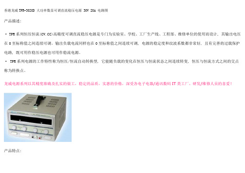
香港龙威TPR-3020D 大功率数显可调直流稳压电源 30V 20A 电路图产品描述:· TPR系列恒压恒流()高精度可调直流稳压电源是专门为实验室、学校、工厂生产线、工程部、维修单位的使用而设计, 其输出电压在0至标称值之间连续可调。
输出负载电流同样也在0至标称值之间连续可调, 电源的稳定度和纹波系数都非常好, 且有完善的过载保护电路, 既可用作稳压电源也可用作稳流电源。
· TPR系列电源的工作特性称为恒压/恒流自动转换型, 它能随负载的变化在恒压与恒流状态之间连续转变, 恒压与恒流方式之间的交点称为转换点。
龙威电源系列以其精度准确及扎实的做工,稳定的品质,实惠的价格,深受各电子电器/通讯数码IT类工厂、研发/维修人员的喜爱!产品特点:· 数字显示输出电压和电流· 在输出标称功率的状态下, 可连续24小时以上的工作· 稳压稳流自动转换· 纹波低、噪音低· 高精度稳压、稳流、输出电压、电流可从0到标称值之间连续可调· 带负载能力强· 具有限流量保护和短路保护功能参数规格:· 输入电压: 220V±10%· 频率: 50/60Hz· 输出电压: DC 0-30V (连续可调)· 输出电流: DC 0-20A (连续可调)· 保护: 电流限量保护及短路保护· 稳压稳定度: ≤0.01% +2mA· 稳流稳定度: ≤0.2% +2mA· 纹波和噪声: ≤1mV (RMS)· 环境温度: -10℃-40℃· 相对湿度: <80%RH· 外形尺寸: 375*260*155 mm· 重量: 17kg· 附件: 说明书、合格证实物图片如下:。
双组输出开关电源(30W-400W)性能参数简介

双组输出开关源(30W-400W)性能参数简介型号:GHD/D30-D400类型:高频开关电源输入电压:100-240(V)V输出功率:30W-400W(W)W简介:105度输出电容器,软启动电流,有效降低AC输入冲击,100%满负荷烧机测试,全球适用AC输入电源,有短路保护,过载保护,内装EMI滤波器,纹波极小!技术参数:性能型号D-120AD-120BCH1CH2CH1CH2直流输出电压5V12V5V24V输出电压容差2%6%2%7%额定输出电流12A5A10A4A输出电流范围2~12A0.5~5A2~10A0.4~4A纹波及噪音60mVp-p120mVp-p60mVp-p150mVp-p进线稳定度0.5%1%0.5%0.5%负载稳定度0.5%5%0.5%6%直流输出功率120W126W效率77%80%直流电压可调范围CH1: 10,-5%CH1: 10,-5%输入电压范围85~132VAC/176~264Hz;47-63Hz,248-370VDC输入电流2.5A/115v 1.25/230V冲击电流冷启动电流35A漏电流<3.5mA/240VAC过载保护105%~135%类型:切断输出复位:自动恢复过电压保护CH1:5.75-6.75V高温保护温度系数0.03%/℃(0~50℃)ON 5V启动、上升、保持时间200ms,50ms,20ms抗震性10~500Hz,2G 10min,/1周期,时长60分,各轴耐压性输入输出间:3KvAC输入与外壳;1.5KvAC输出与外壳;0.5KvAC隔离电阻输入输出间,输入与外壳,输出与外壳:500VDC/100MΩ工作温度、温度-10℃~60℃,20%~90%RH 存储温度、温度-20℃~85℃,10%~95%RH 外形尺寸189*110*50mm重量0.85Kgs安全标准UL195TUV EN60950EMC标准CISPR22(EN55022)等级B,IEC801-2,3,4,IEC 555-2认证。
汉龙EHS30适配器用户手册说明书
Htek EHS30 Adapter User ManualVersion 2.0.4.4.24Feb. 2018Notices InformationCopyrightCopyright © 2005 - 2018 Nanjing Hanlong Technology CO., LTD. All rights reserved.Nanjing Hanlong Technology Co., LTD. owns all the rights to modify and copy this document at any time. And all the illustrations and text in this document are copyright protected. Therefore, no parts of this document may be used or reproduced, transmitted by the third parties for any purposes without the express written permission of Nanjing Hanlong Technology CO., LTD.When this document is made available on , Nanjing Hanlong Technology Co., LTD. gives its right to download and print copies of this content only for private use as a user manual. No parts shall have the right to alter, modify or use as commercial means without prior written permission from Nanjing Hanlong Technology Co., LTD.Safety Instructions●To use the EHS30, please follow the instructions in this user manual.●This EHS30 is only for indoor use. And also avoid in high humidity, water and someother liquids.●Do not use the EHS30 during thunderstorms.●CE●FCCWEEE WarningTo avoid the potential effects on the environment and human health as aresult of the presence of hazardous substances in electrical and electronicequipment, end users of electrical and electronic equipment shouldunderstand the meaning of the crossed-out wheeled bin symbol. Do notdispose of WEEE as unsorted municipal waste and have to collect such WEEE separately.CleaningTo clean the device, use an anti-static cloth. Please avoid cleaning liquids as they might damage the surface or internal electronics of the EHS30.FCC Statement1. This device complies with Part 15 of the FCC Rules. Operation is subject to the following two conditions:(1) This device may not cause harmful interference.(2) This device must accept any interference received, including interference that may cause undesired operation.2. Changes or modifications not expressly approved by the party responsible for compliance could void the user's authority to operate the equipment.NOTE: This equipment has been tested and found to comply with the limits for a Class B digital device, pursuant to Part 15 of the FCC Rules. These limits are designed to provide reasonable protection against harmful interference in a residential installation.This equipment generates uses and can radiate radio frequency energy and, if not installed and used in accordance with the instructions, may cause harmful interference to radio communications. However, there is no guarantee that interference will not occur in a particular installation. If this equipment does cause harmful interference to radio or television reception, which can be determined by turning the equipment off and on, the user is encouraged to try to correct the interference by one or more of the following measures:Reorient or relocate the receiving antenna.Increase the separation between the equipment and receiver.Connect the equipment into an outlet on a circuit different from that to which the receiver is connected.Consult the dealer or an experienced radio/TV technician for help.Table of Content Table of ContentNotices Information (2)Copyright (2)Safety Instructions (2)WEEE Warning (2)Cleaning (2)FCC Statement (3)Table of Content (4)Introduction (5)Description (5)Compatibility (5)Getting Started (6)EHS-30 Package Contents (6)EHS-30 Ports and LEDs Description (6)Installation for Plantronics Headsets (7)Installation for Jabra Headsets (7)Installation for SENNHEISER Headsets (8)IP Phone Configuration (for all Wireless Headsets) (10)Headset Usage (for all Wireless Headsets) (11)Introduction IntroductionDescriptionThe Htek™ EHS30 Wireless Headset Adapter is perfect for connecting Htek phones to supported wireless headsets. It is simple to use and install, and allows the user to control off-hook, talk, and on-hook modes of Htek (Hanlongtek) IP phones from the headset. The EHS Adapter connects between the Htek IP phone and the Wireless Headset base unit.CompatibilityHtek IP Phones *: UC926, UC926E, UC924, UC924E, UC923, UC903, UC862, UC842, UC860, UC840, UC806, UC806T, UC806G, UC804, UC804T and UC804G.Plantronics® Wireless Headsets: Plantronics CS510, CS520, CS540. (Headset bases C052 and C054)Jabra® Headsets: 9400BS (9460), WHB005BS(U) (925), BT2046.SENNHEISER® Wired headset: SC230,SC260,SC660SENNHEISER® Wireless Headsets: DW Pro2,SD Pro2,D10*Firmware Note: Plantronics Headsets require Htek firmware 1.0.3.88 (2015_08_21) or later, and Jabra Headsets require Htek firmware 1.0.3.94 or later.Getting StartedEHS-30 Package ContentsEHS-30 Ports and LEDs Description(1) RJ-12 Port for IP Phone EXT/EHS or Expansion Module(2) Operation LED(3) 3.5mm DC Power Jack (for Plantronics Headsets)(4) RJ-45 Jack (for Jabra Headsets)Installation for Plantronics HeadsetsThe following figure shows the connections between the EHS-30 Adapter, the bottom of the Htek IP Phone, and the Plantronics wireless headset base unit.Steps:1.Connect the Wireless Headset to the RJ-9 Headset port on the IP Phone, using the cord provided by Plantronics.2. Connect the included RJ-12 cord between the EHS-30 Adapter RJ12 Port (Port 1) and the EXT/EHS port of the Htek IP Phone (or to the Expansion Module EXT port, if the expansion module is connected).3. Connect the 3.5mm DC Power Port (Port 3) of the EHS-30 Adapter to the Plantronics Wireless headset using the included 3.5mm DC power cord.Note: For Plantronics Headsets, the RJ45 jack of the EHS-30 Adapter is not used. Installation for Jabra HeadsetsThe following figure shows the connections between the EHS-30 Adapter, the bottom of the Htek IP Phone, and the Jabra wireless headset base unit.Steps:1.Connect Aux Port of the Jabra Wireless Headset to the RJ45 port (Port 4) of the EHS-30 Adapter. (The RJ-45 cord may be supplied by Jabra or obtained separately).2. Connect the included RJ-12 cord between the EHS-30 Adapter RJ12 Port (Port 1) and the EXT/EHS port of the Htek IP Phone (or to the Expansion Module EXT port, if the expansion module is connected).3. Connect the RJ-9 cord from the Jabra Wireless Headset to the Headset jack of the Htek IP phone.Note: For Jabra Headsets, the 3.5mm DC Power jack and cord are not used. Installation for SENNHEISER HeadsetsThe following figure shows the connections between the EHS-30 Adapter, the bottom of the Htek IP Phone, and the SENNHEISER wireless headset base unit.Steps:1. Connect EHS Port of the SENNHEISER Wireless Headset to the RJ45 port (Port 4) of the EHS-30 Adapter. (The RJ-45 cord may be supplied by SENNHEISER or obtainedseparately).2. Connect the included RJ-12 cord between the EHS-30 Adapter RJ12 Port (Port 1) and the EXT/EHS port of the Htek IP Phone (or to the Expansion Module EXT port, if the expansion module is connected).3. Connect Telephone Port of the SENNHEISER Wireless Headset to the Headset jack of the Htek IP phone.Note:For SENNHEISER Headsets, the 3.5mm DC Power jack and RJ45 jack are not used.IP Phone Configuration (for all Wireless Headsets) IP Phone Configuration (for all Wireless Headsets)For Wireless Headset operation, set the following parameters using the IP Phone Web GUI interface:1. Log in to the Web Configuration GUI for the IP Phone (as described in the User Manual).2. Go to Setting -> Preference3. Set “HeadSet Priority” to “Enable”4. Set “Ringer Device For HeadSet” to “Use HeadSet”Refer to the picture below for the correct settings:Headset Usage (for all Wireless Headsets)11Headset Usage (for all WirelessHeadsets)To use the connected Wireless headset (instead of the IP Phone handset), press the Headset key on the keyboard of the phone. The key will light to indicate that you are in Headset mode. Now you can use the wireless headset. To return to normal operation using the handset, press the Headset key again. The key backlight will turn off to indicate that the headset is not active.Please Note :(1) EHS version 0.2 just support Protocol IQ of Jabra wireless headset , But ,EHS version 0.3 support Protocol IQ and DSHG of Jabra wireless headset(2) EHS 30 support two protocol ( IQ , DSHG ) of Jabra Wireless headset . In order to make our phone can recognize which kind of protocol the Jabra Wireless headset use . Please press the off-hook button on headset in the followed two situation:1 : when you use the Jabra wireless headset (protocol DSHG) first time . After connect the devices and complete the webpage setting , please press the off-hook button on headset.2 : When the Jabra wireless headset(Protocol DSHG) in use , after the phone restart or reboot every time , please press the off-hook button on headset.。
RIGOL QGB10000-1110 电源线保证和声明说明书

保证和声明版权©2018苏州普源精电科技有限公司商标信息RIGOL是苏州普源精电科技有限公司的注册商标。
文档编号QGB10000-1110声明●本公司产品受中国及其它国家和地区的专利(包括已取得的和正在申请的专利)保护。
●本公司保留改变规格及价格的权利。
●本手册提供的信息取代以往出版的所有资料。
●本手册提供的信息如有变更,恕不另行通知。
●对于本手册可能包含的错误,或因手册所提供的信息及演绎的功能以及因使用本手册而导致的任何偶然或继发的损失,RIGOL概不负责。
●未经RIGOL事先书面许可,不得影印、复制或改编本手册的任何部分。
产品认证RIGOL认证本产品符合中国国家产品标准和行业产品标准及ISO9001:2015标准和ISO14001:2015标准,并进一步认证本产品符合其它国际标准组织成员的相关标准。
联系我们如您在使用此产品或本手册的过程中有任何问题或需求,可与RIGOL联系:电子邮箱:*****************网址:一般安全概要1.请使用所在国家认可的本产品专用电源线。
2.请确保产品可靠接地。
3.查看所有终端额定值。
4.请使用合适的过压保护。
5.请勿开盖操作。
6.请勿将异物插入排风口。
7.请使用合适的保险丝。
8.避免电路外露。
9.怀疑产品出故障时,请勿进行操作。
10.请保持适当的通风。
11.请勿在潮湿环境下操作。
12.请勿在易燃易爆的环境下操作。
13.请保持产品表面的清洁和干燥。
14.请注意防静电保护。
15.请注意搬运安全。
16.请正确使用前面板BNC输出连接器,仅允许信号输出。
安全术语和符号本手册中的安全术语:警告警告性声明指出可能会造成人身伤害或危及生命安全的情况或操作。
注意注意性声明指出可能导致本产品损坏或数据丢失的情况或操作。
产品上的安全术语:DANGER表示您如果不进行此操作,可能会立即对您造成危害。
WARNING表示您如果不进行此操作,可能会对您造成潜在的危害。
DIY日记0-30V可调线性稳压电源

本人在深圳工作时买了几个大小不一的铝合金外壳(当时看到这些外壳挺漂亮就买了,一直闲置着),其中一个较大一点的外壳尺寸为:134x106x55mm。家里还闲置了一个功率约30W左右的小变压器(该变压器是从旧黑白电视机上拆下来的,有8V和18V两组输出),其厚度还刚好能装到这较大尺寸的铝合金外壳内。既然这么巧合,想不“撮合”它们都找不到理由了。那接下来就是考虑稳压电路部分了,0-30V可调稳压电路可以通过以下几个方案来实现:
(图13)
(图14)
步骤6——附件加工:
好马要配好鞍,接下来还要给电源制作一条漂亮的输出连接线见(图15),线材我选择音箱连接专用线,这种线材阻抗比较低,而且柔软,颜色也好区分。整条线含端子长度为:75cm,个人感觉这种长度使用起来非常舒适,还有一条长的备用线含端子长度为:120cm。
(图15)
步骤7——老化测试:
1.参考电压VREF:2.5V±0.4%(25℃);
2.最大阴极电流范围:-100mA至+150mA;
3.最小阴极电流:0.5mA;
4.最大额定功耗:0.7W(TO-92封装);
431内部结构和引脚排列如附图4所示;
6.TL431的典型应用电路如图5所示;
(图4)
(图5)
工作原理:
如图2所示,220V市电通过S1和F1连接到变压器的输入端,经过变压后分别输出:18V、8V、10V、3V(其中10V和3V绕组是自己以手工穿线的方式加绕的)四组电压,为了降低LM317T的功耗提高电源效率,采用了2个继电器的3级换档电路,换档电路如图6所示,电源输出电压V+加在W2的两端,当W2的滑动触片上获得的分压低于U4的VREF(2.5V)电压时,U4的K、A之间只有微弱的维持电流,J1因得不到足够高的工作电压,其常开触点断开,8VAC绕组通过J1和J2的常闭触点对后级电路供电;当W2的滑动触片上获得的分压高于U4的VREF(2.5V)电压时,U4的阴极电流剧增使J1得到足够工作电压,其常开触点吸合,18VAC绕组通过J1常开触点和J2的常闭触点对后级电路供电。由W3、J2和U5构成的另一级换档电路工作原理类同(可能有人会说换档电路也可以用运放来实现,当然是可以的,只是电路要复杂一点,要是做产品需要考虑成本我会用运放,但偏
TSXPCX3030使用手册

TSXPCX3030 USB-RS485串行多功能编程电缆概述:TSXPCX3030是通过USB接口提供串行连接及RS485信号转换的多功能编程电缆,本电缆的工作电源取自USB端口,不再由PLC的TER口供电,因此本电缆支持与PLC的TER或AUX口通信。
TSXPCX3030可用于Modicon TSX系列PLC与PC或其它不提供传统串行口的设备进行通信。
本电缆可与TSX Premium(57)、TSX Micro(37)、TSX Nano(07)、TSX Naza(08)及Twido PLC 的TER口或AUX口通信口相连。
TSXPCX3030编程电缆上配置有二个位置的拨动开关,用于选择不同的工作模式,摈弃了由PLC 控制RS485收发使能的方式,数据收发转换全部采用自动控制,可用于多点及点对点的应用。
TSX系列PLC的TER口有一个DPT信号引脚,用于确定该终端口的工作方式。
如DPT为高电平,则TER口总是工作在Uni-Telway Master(主站)方式,对PLC编程需在该方式下。
如果DPT 为低电平,则TER口的工作方式由PLC配置决定。
产品结构:开关M/S对应的工作模式特性及技术指标:●支持的操作系统Windows2000/Windows XP●完全兼容USB V1.1和USB CDC V1.1规范●USB总线供电,消耗电流约50mA●波特率:300bps~1Mbps自动适应●适用于TSX Premium、Micro、Naza、Nano和Twido●每台PC只支持一根TSXPCX3030电缆●长度:2.5米,颜色:黑色使用方法:TSXPCX3030需要安装USB设备驱动程序才能使用,要与PLC通信还需要安装最新版本的Uni-Telway或MODBUS驱动程序。
支持TSXPCX3030的Uni-Telway版本:Win2K/XP V1.6WinNT4/95/98/Me/DOS 不支持支持TSXPCX3030的MODBUS版本:Win2K/XP V1.1WinNT4/95/98/Me/DOS 不支持这些驱动程序均包含在随产品发售的光盘上,安装方法请看驱动程序光盘上的说明文档资料,此处不再赘述。
龙威TPR-3002-2D双路可调数显直流电源电路图
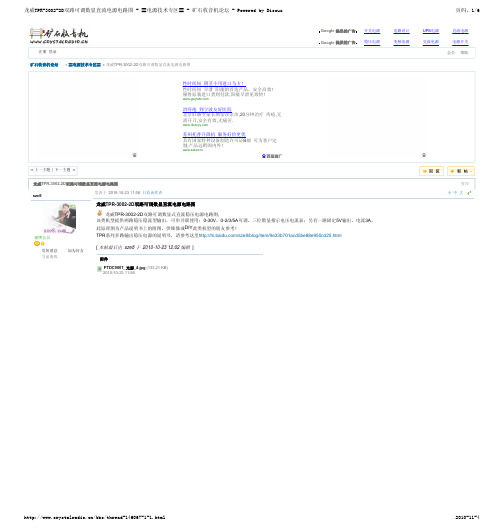
TPR电源方框图_光影_1.jpg (37.77 KB) 2010-10-26 21:45
P9280175_光影_1.jpg (47.33 KB) 2010-10-26 21:45
深圳易吧网上电子城
/bbs/thread-146067-1-1.html
治痔疮 到宁波友好医院 北京肛肠专家长期亲诊亲治,20分钟治疗 痔疮,无 需开刀,安全有效,无痛苦.
苏州托普升降机 服务好价更优 具有国家特种设备制造许可证B级 可为客户定 制,产品远销国内外!
Google 提供的广告 Google 提供的广告
2010-11-4
页码,4/6
小 中 大 4#
注册会员 发短消息 当前离线
sze8
银牌会员 发短消息 当前离线
加为好友 加为好友
TOP
发表于 2010-10-26 21:45 只看该作者
小 中 大 5#
是很复杂啊。。看的人头晕。 不过既然是工厂批量生产,上市大量销售的机型,相信从电路结构、生产工艺、成本考量、稳定性等多方面都是经过确认的了。没哪家工厂不愿意删繁就简,更省事地造产品的。龙威 的这种机型,也只能算是价格实惠的实用型产品吧。应该是不会用高成本的复杂电路的。 补上这个原理框图看起来就简单省事了。呵呵。顺便也上个实物靓照。看起来直观一些。。
2010-11-4
龙威TPR-3002-2D双路可调数显直流电源电路图 - 〓电源技术专区〓 - 矿石收音机论坛 - Powered by Discuz!
页码,3/6
qteng
深圳易吧网上电子城 淘宝四钻店/
发表于 2010-10-24 14:49 只看该作者
[ 本帖最后由 泰山鸿润 于 2010-10-29 21:42 编辑 ]
AP80N03DF 80A 30V PDFN3x3-8L
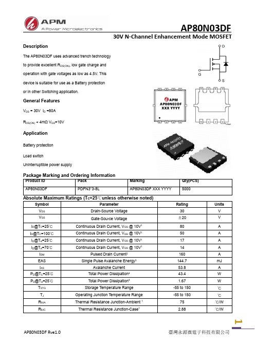
1DescriptionThe AP80N03DF uses advanced trench technology to provide excellent R DS(ON), low gate charge and operation with gate voltages as low as 4.5V. This device is suitable for use as a Battery protection or in other Switching application.General FeaturesV DS = 30V I D =80A R DS(ON) < 4mΩ V GS =10VApplicationBattery protection Load switchUninterruptible power supplyV DD=15V , V GS=10V ,R G=1.5I D=20A1.The data tested by surface mounted on a 1 inch2 FR-4 board with 2OZ copper.2.The data tested by pulsed , pulse width ≦ 300us , duty cycle ≦ 2%3.The EAS data shows Max. rating . The test condition is V DD=25V,V GS=10V,L=0.1mH,I AS=53.8A4.The power dissipation is limited by 150℃ junction temperature5 .The data is theoretically the same as I D and I DM , in real applications , should be limited by total power dissipation.23175Fig.1 Typical Output CharacteristicsFig.2 On-Resistance vs. G-S VoltageFig.3 Forward Characteristics of Reverse Fig.4 Gate-Charge CharacteristicsFig.5 Normalized V GS(th) vs. T J4I AS V GS BV DSS V DD EAS=12L x I AS 2 xBV DSS BV DSS -V DDFig.8 Safe Operating Area Fig.9 Normalized Maximum Transient Thermal Impedance Fig.7 Capacitance Fig.10 Switching Time WaveformFig.11 Unclamped Inductive Switching WaveformPackage Mechanical Data-DFN3*3-8L-JQ Single5Attention1,Any and all APM Microelectronics products described or contained herein do not have specificationsthat can handle applications that require extremely high levels of reliability, such as life support systems, aircraft's control systems, or other applications whose failure can be reasonably expected to result inserious physical and/or material damage. Consult with your APM Microelectronics representative nearestyou before using any APM Microelectronics products described or contained herein in such applications.2,APM Microelectronics assumes no responsibility for equipment failures that result from using productsat values that exceed, even momentarily, rated values (such as maximum ratings, operating condition ranges, or other parameters) listed in products specifications of any and all APM Microelectronicsproducts described or contained herein.3, Specifications of any and all APM Microelectronics products described or contained here instipulate the performance, characteristics, and functions of the describ ed products in the independent state, and arenot guarantees of the performance, characteristics, and functions of the described products as mountedin the customer’s products or equipment. To verify symptoms and states that cannot be evaluated in an independent device, the customer should always evaluate and test devices mounted in the customer’s products or equipment.4, APM Microelectronics Semiconductor CO., LTD. strives to supply high quality high reliability products. However, any and all semiconductor products fail with some probability. It is possible that theseprobabilistic failures could give rise to accidents or events that could endanger human lives that couldgive rise to smoke or fire, or that could cause damage to other property. When designing equipment,adopt safety measures so that these kinds of accidents or events cannot occur. Such measures includebut are not limited to protective circuits and error prevention circuits for safe design, redundantdesign,and structural design.5,In the event that any or all APM Microelectronics products(including technical data, services) describedor contained herein are controlled under any of applicable local export control laws and regulations, such products must not be exported without obtaining the export license from the authorities concerned in accordance with the above law.6, No part of this publication may be reproduced or transmitted in any form or by any means,electronic or mechanical, including photocopying and recording, or any information storage or retrieval system, or otherwise, without the prior written permission of APM Microelectronics Semiconductor CO., LTD.7, Information (including circuit diagrams and circuit parameters) herein is for example only; it is not guaranteed for volume production. APM Microelectronics believes information herein is accurate and reliable, but no guarantees are made or implied regarding its use or any infringements of intellectualproperty rights or other rights of third parties.8, Any and all information described or contained herein are subject to change without notice due toproduct/technology improvement,etc. When designing equipment, refer to the "Delivery Specification" forthe APM Microelectronics product that you Intend to use.6Copyright Attribution“APM-Microelectronice”7。
固纬电源说明书3030DQ

GPC-HIGH SERIES 操作手册i目录 页次 1. 产品介绍…..........................…………………….………….. 1 2.产品规格……………………………………………………..32-1.一般规格…………………………………………………2-2.操作模式…………………………………………………2-3.定电压操作………………………………………………2-4.定电流操作………………………………………………2-5.追踪操作…………………………………………………2-6.电表………………………………………………………2-7.5V 固定输出规格………………………………………..2-8.绝缘度…………………………………………………… 3 4 4 4 5 5 6 6 3. 动作原理……………………………………………………..7 4.面板介绍 (9)4-1.前面板……………………………………………………4-2.后面板……………………………………………………9 11 5.操作说明 (15)5-1.使用前注意事项………………………………………...5-2.限流点的设定(Current Limit)…………………………..5-3.定电压/定电流的特性(Constant V oltage/Constant Current)……………………………………..5-4.操作模式…………………………………………….......15 16 16 186.一般维修……………………………………………………..236-1.保险丝的更换……………………………………………6-2.电源电压的变换………………………………………...6-3.调整………………………………………………………6-4.清洁………………………………………………………23 23 24 27GPC-HIGH SERIES 操作手册11.产品介绍GPC 系列直流电源供应器是一部携带式可调整的多功能仪器,特别设计应用在电源操作的放大器,逻辑线路,正负电压误差非常小的精密仪器系统的追踪上,或需要用到三组独立电源的单体线路上,可称得上是一部非常实用又方便的仪器。
龙威开关电源说明书
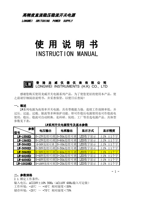
参数型号LW-1550KD 0-15V连续可调0-50A连续可调LED数字显示±1% ±1个字LW-1560KD 0-15V连续可调0-60A连续可调LED数字显示±1% ±1个字LW-3040KD0-30V连续可调0-40A连续可调LED数字显示±1% ±1个字LW-3050KD 0-30V连续可调0-50A连续可调LED数字显示±1% ±1个字LW-3060KD 0-30V连续可调0-60A连续可调LED数字显示±1% ±1个字LW-6020KD 0-60V连续可调0-20A连续可调LED数字显示±1% ±1个字LW-6030KD 0-60V连续可调0-30A连续可调LED数字显示±1% ±1个字LW-10020KD 0-100V连续可调0-20A连续可调LED数字显示±1% ±1个字- 1 -高精度直流稳压稳流开关电源使 用 说 明 书INSTRUCTION MANUAL2.1.额定工作条件:输入电压:AC220V±10% 50Hz(AC110V 60Hz输入可定做)工作环境:-10℃ ~ +40℃ 相对湿度<80%储存环境:-20℃ ~ +70℃ 相对湿度<70%LW系列电源为高效率开关电源,具有带载能力强,连续工作故障率低,并有过压、过温、过载、限流等多种保护功能。
即可作稳压电源使用也可作稳流电源使用,稳压、稳流可自动转换。
是科研、院校、工厂等首选电源产品。
具体型号参数见下表:二、参数规格电压输出电流输出显示方式显示精度 LONGWEI SWITCHING POWER SUPPLY香 港 龙 威 仪 器 仪 表 有 限 公 司LONGWEI INSTRUMENTS (H.K) CO., LTD感谢您购买使用龙威开关电源系列产品,为了使您更好的使用本产品,使用之前请仔细阅读说明书,并妥善保管,以便日后查阅!一、概述2.2.电源输出参数:电压稳定度:≤0.2%电流稳定度:≤0.5%负载稳定度:≤0.5%纹波及噪声:≤1%(有效值)三、面板控制3.1.前面板:(1)电流显示:用于显示当前电流值,单位:安培(A)。
SMD-30 30 30 30-XS伺服驱动器硬体操作说明书
SMD-30/30/30/30-XS 硬体操作说明书匯出日期:2023-05-10修改日期:2021-04-19••••••••••••••••目录序言适用机型硬体规格说明外观介绍外形尺寸驱动器规格搬运与安装搬运安装环境条件与注意事项配线与信号周边装置接线图驱动器的连接器与端子说明回生电阻选用简易回生电阻选择详细回生电阻选择版本号编修日期编修内容作者审查核准V1.22018/08/01将重覆内容整理为Source ,并于硬体操作说明书中include 对应内容新增内容翻译張芷瑜V1.32020-7-23刪去電容吸收能量Ec黃揚程V1.42022-6-30修正为四合一操作说明书带电池盒乃维HomePageSYNTEC伺服操作说明书文件资讯文件履历文件资讯文件履历1 序言感谢您长期对本公司产品的使用与支持。
本公司伺服团队不断致力於各项产品的研发,期许本公司产品与服务能给使用者带来最大的效益。
新代高性能驱动器系列产品为本公司最新推出之伺服驱动器,本产品使用高品质之元件与材料,并经过严格测试,采用精密向量控制,具有高精确度、高稳定性、高效率之特性。
本使用说明内容包括驱动器的硬体规格、安装、配线与讯号,能提供给使用者最正确的指引与操作,为充分发挥产品应有的优异性能与维护人员及设备的安全,在使用前请详细阅读本使用手册,并且妥善保存,以备日後调校与保养时使用,若有任何疑虑,请与本公司联络,本公司专业人员将竭诚为您服务。
2 适用机型本操作手册适用於新代SMD-30/30/30/30-XS驱动器3 硬体规格3.1 说明每部驱动器在出厂前均经过详细品管检查与防撞包装处理,请使用者收到产品後应先检查外观有无撞击损伤,并将外盒与产品上之序号做比对是否一致,若有不符,请第一时间与本公司联络。
型号说明3.2 外观介绍SMD-30/30/30/30-XS驱动器功能模块说明A M3串行通讯端口连接上位控制器与下一站驱动器,串行通讯100MbpsB Mini USB端口连接个人计算机C I/O讯号端口外接电池端口连接I/O设备(急停、警示灯…等)连接绝对型编码器供电用电池D STO讯号端口STO接口,2组安全输入,1组安全功能回授E编码器回授由上至下分别为第一至第四埠。
SL2128D

◆电气参数
项目 电源电压 Vcc 启动电压 Vcc 关闭电压 Vcc 电源电流 启动时间 OC 保护电压 功率管耐压 功率管最大电流 峰值电流保护 掁荡频率 变频频率 抖频步进频率 温度保护 PWM 占空比 控制电压 Fb 测试条件 AC 输入 85V------265V AC 输入 85V------265V AC 输入 85V------265V Vcc=5V,Fb=2.2V AC 输入 85V L=1.2mH Ioc=1mA Vcc=5V,Fb=1.6V---3.6V Vcc=5V,Fb=1.6V---3.6V Vcc=5V,Fb=1.6V---2.8V Vcc=4.6V,Fb=2.8V---3.6V Vcc=4.6V,Fb=1.6V---2.8V Vcc=4.6V,Fb=1.6V---3.6V Vcc=4.6V,Fb=1.6V---3.6V AC 输入 85V------265V 最小 4 4.8 3.6 10 --460 700 600 650 50 0.05 0.8 120 5 1.6 典型 5 5 4 20 --480 --660 720 65 --1 125 ----最大 6 5.2 4.2 30 500 500 --700 800 70 65 1.2 130 75 3.6 单位 V V V mA mS V V mA mA Khz Khz Khz
Vs =85*1.3=110V (考虑了线路压降及整流压降)。
2.4、计算 PWM 导通时间
Ton =(1/F)*D=(1/65)*0.5=7.7uS
2.5、计算原边匝数 N p
Np
Vs Ton 110 7.7 85匝 Bac Ae 0.2 50
N p -------------------------原边匝数 Vs ---------------------------原边直流电压(最低电压值) Ton --------------------------导通时间 Bac ------------------------交变工作磁密(mT),设为 0.2 Ae ---------------------------磁心有效面积(m m 2 ),EE25 磁心为 50 m m 2
REF3030AIDBZR
SHENZHEN XUNFENG TECHNOLOG LTD. HTTP:/ 电话:13751074754 传真:0755-83259733
深圳市福田红荔路上步工业区上航大厦 302 室
规 格 承 认 书
SPECIFICATON FOR APPROVAL 承认书编号: SZ-XF-0105 客 户 CUSTOMER 深圳科士达科技股份有限公司
q MicroSIZE PACKAGE: SOT23-3 q LOW DROPOUT: 1mV q HIGH OUTPUT CURRENT: 25mA q HIGH ACCURACY: 0.2% q LOW IQ: 50µA max q EXCELLENT SPECIFIED DRIFT PERFORMANCE: 50ppm/°C (max) from 0°C to +70°C 75ppm/°C (max) from –40°C to +125°C
PRODUCT REF3012
PACKAGE-LEAD SO T23-3
"
REF3020
"
SOT23-3
"
DBZ
"
–40°C to +125°C
"
R30B
"
REF3025
"
SOT23-3
"
DBZ
"
–40°C to +125°C
"
R30C
"
REF3030
"
SOT23-3
"
DBZ
"
–40°C to +125°C
ELECTROSTATIC DISCHARGE SENSITIVITY
JAD1812 AC-DC 开关电源驱动器说明书
载损耗会小于75mW。
CV模式下的可编程线缆压降补偿
在智能手机充电器应用中,电池总是通过数据线连接到适配
器,这可能使得充电器输出在电池上的电压降低百分之几的电压降。
在JAD1812中,通过内部电流源(由CDC 模块调制,如右图所示)
流入电阻分压器,在FB引脚产生一个偏置电压。电流大小与开关周期
◆内置线电压和负载恒流补偿
◆脉冲前沿消隐 (LEB)
◆负载短路保护 (SLP)
◆逐周期电流限制
◆ FB 管脚开路/短路保护
◆ VDD 过压/欠压/钳位保护
◆过热保护(OTP)
◆DIP7封装
◆ 电池充电器和适配器
◆ 手机电池充电器
◆ AC/DC 电源适配器
◆ LED照明电源
封装形式:
JAD1812 采用 DIP7 封装
提供高性价比的解决方案,可提供高精度的CC/CV控制,适用于充电器、适配器和内置电 源等应用。在恒压CV模式,
采用准谐振与多技术提高效率并消除音频噪音,使得系统满足6级能效标准,可调输出线补偿功能使系统获得更好的负
载调整率;在恒流CC模式,输出电流和功率可以通过CS电阻进行调节。
JAD1812提供全面保护:欠压闭锁(UVLO)、VDD 过压保护(VDD_OVP)、逐周期过流保护(OCP)、短路
典型应用
捷捷微电(深圳)有限公司
股票代码:300623
JAD1812 AC-DC 开关电源驱动器说明书
打标说明及管脚分布
DIP-7
管脚图
丝印字符
丝印字符说明
JAD1812
芯片型号
年号
左示意图
周号
功率30W的小型开关电源方案分享之主电路设计
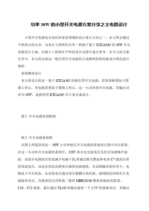
功率30W的小型开关电源方案分享之主电路设计
小型开关电源是目前民用家居领域的设计重点方向之一,本文将会通过今明两天的分享,为各位工程师们分享一种基于基于ICE2A365的30W开关电源设计方案,以便于工程师在平时的设计过程中进行参考。
在今天的方案分享中,本文将会就这一稳压型开关电源的主电路和控制电路设计情况进行简析。
系统整体设计
本文所设计的这一基于ICE2A365的稳压型开关电源,其原理框图如下图图1所示,其电路原理如下图图2所示。
这一小功率的开关电源,其输出功率为30W,选择使用ICE2A365芯片来完成设计。
图1 开关电源原理框图
图2 开关电源系统图
从图2所提供的这一30W小功率稳压开关电源的系统设计图中可以看到,在这一小功率开关电源的系统中,220V的市电交流电压先经过电源噪声滤波,该部分电路的目的是减少电磁干扰;再通过桥式整流和电容C7滤波后得到直流高压。
该高压供给高频变压器的初级绕组,在高频脉冲的作用下,电路处于开关状态,从而使电压通过变压器耦合到次级,副绕组给控制芯片电源提供电压,次级再经过肖特基二极管MBR20100整流和滤波电路I2、
C10、C12滤波,最后通过TL43l给输出提供一个2.5V的基准电压。
其输出。
Eaton Moeller MSC-D DOL 开关搭载器 102979 产品说明说明书

Eaton 102979Eaton Moeller® series MSC-D DOL starter, 380 V 400 V 415 V: 11 kW, Ir= 20 - 25 A, 24 V DC, DC voltageGeneral specificationsEaton Moeller® series MSC-D DOL starter1029794015081028184156 mm 200 mm 45 mm 1.14 kgUL Category Control No.: NKJH UL60947-4-1A CSA File No.: 012528 UL File No.: E123500 CSACSA Class No.: 3211-04 IEC/EN 60947-4-1 UL CECSA-C22.2 No. 14 (on request) UL 508 (on request) CSA-C22.2 No. 14-10Product NameCatalog Number EANProduct Length/Depth Product Height Product Width Product Weight Certifications25 AIs the panel builder's responsibility. The specifications for the switchgear must be observed.11 kW230 - 415 V AC0 A0 VMeets the product standard's requirements.Is the panel builder's responsibility. The specifications for the switchgear must be observed.Mounting on Busbar 60 mmDoes not apply, since the entire switchgear needs to be evaluated.0 kW0 kWMeets the product standard's requirements.24 VShort-circuit release0DA-DC-00004911.pdfDA-DC-00004879.pdfeaton-manual-motor-starters-device-msc-d-dol-starter-wiring-diagram.epseaton-manual-motor-starters-adapter-msc-d-dol-starter-dimensions-002.epseaton-manual-motor-starters-adapter-msc-d-dol-starter-3d-drawing.eps ETN.MSC-D-25-M25(24VDC)_BBA.edzSimple, flexible and safe! Distribution system for motor-starter combinationsIL03402015ZIL03402010ZDA-CS-msc_d_bba_bg2DA-CD-msc_d_bba_bg2Rated operational current for specified heat dissipation (In) 10.11 Short-circuit ratingRated operational power at AC-3, 380/400 V, 50 Hz Rated operational voltageRated conditional short-circuit current, type 1, 480 Y/277 V Rated control supply voltage (Us) at AC, 50 Hz - min10.4 Clearances and creepage distances10.12 Electromagnetic compatibilityMounting method10.2.5 LiftingRated power at 575 V, 60 Hz, 3-phaseRated power at 460 V, 60 Hz, 3-phase10.2.3.1 Verification of thermal stability of enclosures Rated control supply voltage (Us) at DC - minFitted with:Number of pilot lightsShort-circuit current rating (basic rating)Declarations of conformity Diagramas de cableado DibujoseCAD modelFolletosInstrucciones de instalación mCAD model1 A, max. Fuse, SCCR (UL/CSA)5 kA, SCCR (UL/CSA)15 A, max. CB, SCCR (UL/CSA)Rated control supply voltage (Us) at AC, 50 Hz - max0 VCoordination type210.8 Connections for external conductorsIs the panel builder's responsibility.Coordination class (IEC 60947-4-3)Class 2Rated conditional short-circuit current, type 1, 600 Y/347 V0 AAmbient operating temperature - max55 °CRated operational power at AC-3, 220/230 V, 50 Hz5.5 kWConnection to SmartWire-DTNoNumber of command positionsStatic heat dissipation, non-current-dependent Pvs0.9 WElectrical connection type of main circuitScrew connectionElectrical connection type for auxiliary- and control-current circuit Screw connectionPower consumption (sealing) at DC0.5 WRated control supply voltage (Us) at DC - max24 V10.9.3 Impulse withstand voltageIs the panel builder's responsibility.Ambient operating temperature - min-25 °C10.6 Incorporation of switching devices and componentsDoes not apply, since the entire switchgear needs to be evaluated.10.5 Protection against electric shockDoes not apply, since the entire switchgear needs to be evaluated.ClassCLASS 10 A10.13 Mechanical functionThe device meets the requirements, provided the information in the instruction leaflet (IL) is observed.10.2.6 Mechanical impactDoes not apply, since the entire switchgear needs to be evaluated.10.9.4 Testing of enclosures made of insulating materialIs the panel builder's responsibility.10.3 Degree of protection of assembliesDoes not apply, since the entire switchgear needs to be evaluated.Heat dissipation per pole, current-dependent Pvid5 WActuating voltage24 V DCVoltage typeDCSwitching capacity (auxiliary contacts, general use)1 A, 250 V DC, (UL/CSA)15 A, 600 V AC, (UL/CSA)Overload release current setting - min20 AEquipment heat dissipation, current-dependent Pvid15 WHeat dissipation capacity Pdiss0 WRated operational current (Ie)21.7 ASuitable forAlso motors with efficiency class IE3Number of auxiliary contacts (normally closed contacts)Rated conditional short-circuit current (Iq), type 2, 380 V, 400 V,415 V50000 APower consumption0.9 W10.2.3.2 Verification of resistance of insulating materials to normal heatMeets the product standard's requirements.10.2.3.3 Resist. of insul. mat. to abnormal heat/fire by internal elect. effectsMeets the product standard's requirements.Overload release current setting - max25 A10.9.2 Power-frequency electric strengthIs the panel builder's responsibility.Overvoltage categoryIIIDegree of protectionIP00NEMA OtherPollution degree3Rated control supply voltage (Us) at AC, 60 Hz - min0 V10.7 Internal electrical circuits and connectionsIs the panel builder's responsibility.Rated impulse withstand voltage (Uimp)6000 V ACConnectionScrew terminals10.10 Temperature riseThe panel builder is responsible for the temperature rise calculation. Eaton will provide heat dissipation data for the devices.FunctionsTemperature compensated overload protectionRated conditional short-circuit current (Iq), type 2, 230 V 50000 ATypeStarter with Bi-Metal releaseEaton Corporation plc Eaton House30 Pembroke Road Dublin 4, Ireland © 2023 Eaton. Todos los derechos reservados. Eaton is a registered trademark.All other trademarks areproperty of their respectiveowners./socialmediaMeets the product standard's requirements.Meets the product standard's requirements.Meets the product standard's requirements.388 A0 V25 A Direct starter1Max. 2000 mA600, AC operated (UL/CSA) P300, DC operated (UL/CSA)10.2.2 Corrosion resistance10.2.4 Resistance to ultra-violet (UV) radiation 10.2.7 InscriptionsShort-circuit release (Irm) - max Rated control supply voltage (Us) at AC, 60 Hz - max Rated operational current (Ie) at AC-3, 380 V, 400 V, 415 V Model Number of auxiliary contacts (normally open contacts)Altitude Switching capacity (auxiliary contacts, pilot duty)。
CEDES LPS 100 202 安装及说明书

CEDES安装及操作手册LPS 100/20285…265VAC/120…375VDC 双通道开关电源适用与不同类型的传感器连接使用中文跟传感器配套使用的专用开关电源manufactured under ISO 9001: 2000重要注意事项请注意遵守本手册中的安装说明,否则会引起客户的投诉和严重的召回事件。
请将本手册放置在现场。
© CEDES / Version 1.1 / March 22, 2010Part No.85…265VAC/120…375VDC双通道开关电源安装及操作手册请勿在爆炸性、放射性或化学性的环境中使用本产品!此种环境中只能使用特殊的、经认可的设备,不然会引起严重的伤亡事故或损害!2 © CEDES / March 201085…265VAC/120…375VDC双通道开关电源安装及操作手册①继电器输出接线排- 包含继电器输出通道1 (NC/NO)、继电器输出通道2 (NC/NO)②模式选择开关模式1 - 不带逻辑控制模式2 - 带逻辑控制(与门、或门)功能。
③逻辑输出选择开关逻辑“或”输出(”≥1”)逻辑“与”输出(”&”)④AC电源输入接线排⑤继电器输出状态指示灯(针对继电器输出通道1)⑥继电器输出状态指示灯(针对继电器输出通道2)⑦电源输入状态指示灯⑧传感器信号输入接线排重如果选压输© CEDES / March 2010 34 © CEDES / March 20103. 安装步骤 安装过程应严格按照如下步骤进行:1.切断主电源,保证安装设备处于待检状态 ·开关电源可以通过设置在其底部的燕尾槽被固定在靠近门机控制器的位置上。
2. 传感器的固定安装 3. 开关电源的固定安装 4. 开关电源的电气安装 5. 上电并进行正常功能调试 3.1. 切断主电源为了您自身安全,在安装开关电源之前先切断主电源,并保证安装设备处于待检状态。
艾特顿GHB3030型号电源保护设备说明说明书

Eaton GHB3030Eaton Series C complete molded case circuit breaker, G-frame, GHB, Complete breaker, Fixed thermal, Fixed magnetic trip type, Three-pole, 30 A, 480Y/277 Vac, 125/250 Vdc, 50/60 HzGeneral specificationsEaton Series C complete molded case circuit breakerGHB30307866799112732.63 in 4 in3 in 1.75 lb Eaton Selling Policy 25-000, one (1) year from the date of installation of theProduct or eighteen (18) months from thedate of shipment of the Product,whichever occurs first.Federal Specifications Classification W-C375BUL ListedProduct NameCatalog Number UPCProduct Length/Depth Product Height Product Width Product Weight WarrantyCompliancesCertificationsSeries C65 kAIC at 240 Vac14 kAIC at 480Y/277 Vac Molded case circuit breaker GGHB50/60 HzComplete breaker480Y/277 Vac, 125/250 Vdc 30 AFixed thermal, fixed magnetic Three-pole Application of Tap Rules to Molded Case Breaker TerminalsUL listed 100%-rated molded case circuit breakersApplication of Multi-Wire Terminals for Molded Case Circuit BreakersCircuit breaker motor operators product aidPlug-in adapters for molded case circuit breakers product aid Current limiting Series C molded case circuit breakers product aid Power metering and monitoring with Modbus RTU product aid StrandAble terminals product aidMotor protection circuit breakers product aidMOEM MCCB Product Selection GuideMulti-wire lugs product aidBreaker service centersEaton's Volume 4—Circuit ProtectionMolded case circuit breakers catalogG-frame Molded Case Circuit Breaker DrawingSeries C GB/GHB/GDB Circuit Breakers - ILCircuit Breakers ExplainedCircuit breakers explainedSeries C F-Frame molded case circuit breakersSeries C G-Frame molded case circuit breakers time current curves MOEM MCCB product selection guideSeries C G-Frame Time Current CurvesEaton Specification Sheet - GHB3030Series C J-Frame molded case circuit breakers time current curves Type GHB/GHC/GD/GPS 2 and 3-pole, 15-100A Time Curve Selling Policy 25-000 - Distribution and Control Products and ServicesSeriesInterrupt ratingTypeFrameCircuit breaker type Frequency ratingCircuit breaker frame type Voltage rating Amperage RatingTrip TypeNumber of poles Application notesBrochuresCatalogsDrawingsInstallation instructions MultimediaSpecifications and datasheetsTime/current curves Warranty guidesEaton Corporation plc Eaton House30 Pembroke Road Dublin 4, Ireland © 2023 Eaton. All Rights Reserved. Eaton is a registered trademark.All other trademarks areproperty of their respectiveowners./socialmedia。
GPS-3030DD 直电源供应器 说明书
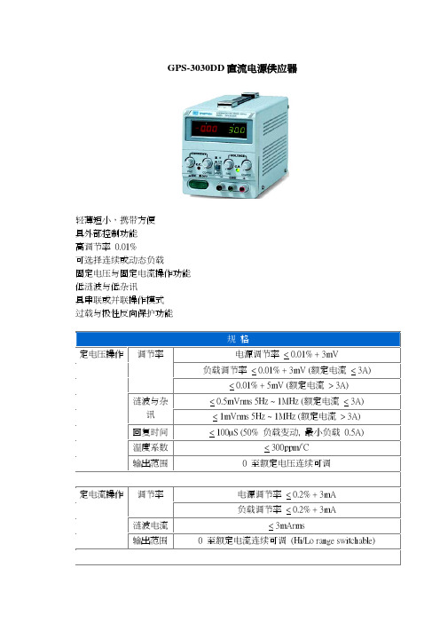
GPS-3030DD直流电源供应器轻薄短小,携带方便具外部控制功能高调节率 0.01%可选择连续或动态负载固定电压与固定电流操作功能低涟波与低杂讯具串联或并联操作模式过载与极性反向保护功能规格定电压操作调节率电源调节率 < 0.01% + 3mV负载调节率 < 0.01% + 3mV (额定电流 < 3A)< 0.01% + 5mV (额定电流 > 3A)< 0.5mVrms 5Hz ~ 1MHz (额定电流 < 3A) 涟波与杂讯 < 1mVrms 5Hz ~ 1MHz (额定电流 > 3A) 回复时间 < 100µS (50% 负载变动, 最小负载 0.5A)温度系数 < 300ppm/°C输出范围 0 至额定电压连续可调电源调节率 < 0.2% + 3mA调节率定电流操作负载调节率 < 0.2% + 3mA涟波电流 < 3mArms输出范围 0 至额定电流连续可调 (Hi/Lo range switchable)V-表及 I-表各一2.5 class 指针式 尺寸 50 x 50 mm3 1/2 位数 0.5" LED 显示3 1/2 位数 0.39" LED 显示 (GPS-3030DD)表头 数字式 准确度 + (0.5% 读值 + 2 位数)机壳对端子 20MW or above ( DC 500V ) 绝缘机壳对电源线30MW or above ( DC 500V )使用电源 交流 100V/120V/220V/240V+10%, 50/60Hz附件操作手册 x 1, 电源线 x 1, 测试线 GTL-105 x 1 (<3A) or GTL-104 x 1(<10A)尺寸 128(宽) x 145(高) x 285(长) mmGPS 系列直流电流供应器选型表 机 种 输出电压(V) 输出电流 (A) 表头显示 重量 (kg)GPS-1830 0~18 0~3 V-表 x 1, 1-表 x 1 4 GPS-18500~18 0~5 V-表 x 1, 1-表 x 1 5 GPS-3030 0~30 0~3 V-表 x 1, 1-表 x 1 5 GPS-6010 0~60 0~1 V-表 x 1, 1-表 x 1 5 指针式 GPR-3030 0~30 0~3 V-表 x 1, 1-表 x 1 5 GPS-1830D0~18 0~3 3½ 位数 x 1 4 GPS-1850D 0~18 0~5 3½ 位数 x 1 5 GPS-3030D 0~30 0~3 3½ 位数 x 1 5 数位式GPS-3030DD0~300~33½ 位数 x 25。
