NP48N055CHE中文资料
NP系列微型磁力齿轮泵中文样本
NP- FluidTechnologysolution-微型磁力齿轮泵Specialist索 富您忠实的伙伴您忠实的伙伴上海索富实业有限公司成立于2010,是一家以市场需求为先导、技术创新为核心、坚持为客户提供优质产品和服务的微型磁力齿轮泵公司。
我们的目标是成为世界领先的微型泵设计和生产者。
公司目前在上海拥有研发和销售中心,在福建三明市拥有生产基地。
公司人员来自外企管理和技术团队以及国内技师团队,具有微型特种泵15年以上的技术和市场经验以及40年的产品生产和管理经验。
公司拥有特种材料应用、专业型线设计、高精度加工、一次注塑成型、精密装配到检测的全套自主技术,已经获得12项专利,包含4项发明专利。
公司适应市场需求,每年都有新产品推向市场,都有新技术得到开发和应用。
项目进入中国创新创业大赛全国总决赛并获得省级二等奖。
全系列产品获得欧盟CE认证。
多年来我们的产品行销国内外,在医疗设备、化工装置、工程机械、商用机械、实验室分析、柴油机尾气后处理(SCR)、润滑系统、植保无人机、工业雾化系统、冷却系统、燃料电池、锂电池生产等领域得到广泛应用。
产品的稳定、长寿命、高压性能达到甚至超过欧美同类进口产品,获得国内外客户的好评。
我们一直致力于以高度的专业性和贴近客户的服务为您提供最适合需求的完整解决方案。
您的需求就是我们的使命。
企业简介Company pro le 上海索富实业有限公司成立于2010,是一家以市场需求为先导、技术创新为核心、坚持为客户提供优质产品和服务的微型磁力齿轮泵公司。
我们的目标是成为世界领先的微型泵设计和生产者。
公司目前在上海拥有研发和销售中心,在福建三明市拥有生产基地。
公司人员来自外企管理和技术团队以及国内技师团队,具有微型特种泵15年以上的技术和市场经验以及40年的产品生产和管理经验。
公司拥有特种材料应用、专业型线设计、高精度加工、一次注塑成型、精密装配到检测的全套自主技术,已经获得12项专利,包含4项发明专利。
英特吉NPR48整流模块

上升斜率:可设顶,缺省 8A/s 保护:限流值:可调范围 30-120%RRC,缺省限流点:100%RRC
典型值≤5mV(150kHz-30MHz)
共4页 第2页
离散杂音:典型值≤1mV(3.4kHz-150kHz) 典型值≤1mV(150kHz-200kHz) 典型值≤1mV(200kHz-500kHz) 典型值≤0.1mV(500kHz-30MHz)
可靠性指标 MTBF(根据 HRD5 计算)大于 256953 小时(29.3 年)
当提供通常的负载电流时,R3048(NPR48)运行在最佳状态,达到大于 92﹪的效率, 运行成本极低。R3048(NPR48)能提供恒流及恒功率的运行模式。 特征
整流器(Hot-Swap)快速在线更换 由监控模块自动设定 智能化微处理器控制 高功率密度 高效和一致性功率因数 宽泛的交流电源条件 宽泛的输出电压范围 恒定功率输出或恒定电流输出模式 可现场维护的空气滤清器 符合国际标准 交流输入 标称:220V/50Hz 相电压范048(NPR48)整流模块
英特吉 R3048(NPR48)整流模块可广泛应用于交换、无线和传输。综合使用了卓越的 开关技术及高可靠性的风冷设计,使得 R3048(NPR48)成为灵活、可靠且高效的整流器。 可在 70℃的环境温度,宽范围的交流输入等恶劣环境中正常运行,并具有抗多重浪涌的能 力。
机械参数 机械参数(高、宽、深):222mm(5U),70mm(14E),326mm 重量:5.3kg 连接器:三合一集成化插件:交流/直流/数据
山洋R系列驱动器说明书中文版

˙ػ相ց关ͱ机ͷ械݁的߹结ɾ合ɾ·ɾ·ɾ·ɾ·ɾ·ɾ·ɾɾ·ɾ·ɾ·ɾ·ɾ·ɾ·̎ʵ̒
˙औ允许ڐ承༰受ՙ负ॏ载ɾ ·ɾ·ɾ·ɾ·ɾ·ɾ·ɾɾ·ɾ·ɾ·ɾ·ɾ·ɾ·ɾ·̎ʵ̔
̎ɽ安औ装Γ ͚ <[α伺ʔ服Ϙ驱Ξ动ϯ器ϓ]>
SANYO DENKI 010-51298818
SANYO DENKI 010-51298818
SANYO DENKI 010-51298818
SANYO DENKI 010-51298818
SANYO DENKI 010-51298818
SANYO DENKI 010-51298818
SANYO DENKI 010-51298818
SANYO DENKI 010-51298818
SANYO DENKI 010-51298818
SANYO DENKI 010-51298818
SANYO DENKI 010-51298818
SANYO DENKI 010-51298818
SANYO DENKI 010-51298818
SANYO DENKI 010-51298818
SANYO DENKI 010-51298818
SANYO DENKI 010-51298818
SANYO DENKI 010-51298818
SANYO DENKI 010-51298818
ର即ྲྀ使ɼ是对ࣹͳ流Ͳ或ʹ者Α辐Δ射Թ造্成ঢ温͕度ߟ͑的Β上Ε升Δ,߹都Ͱ必须ɺ保αʔ证Ϙ伺Ξ服ϯ驱ϓͷ动ۙ器͘的附ඞͣ近的ˆ温Ҏ度Լʹ在ͳ55Δ℃Α以͏ʹ下͠。
日立电梯元件代码

日立电梯元件代码分类:电梯资料2009.9.19 23:44 作者:s9******* | 评论:0 | 阅读:927 日立电梯元件代码1 A 门电机YPVF2 ACR 电流控制调整电子板YPVF、VFM(H)G、HVF、NPX3 AD 模数电子板YPVF4 ALARM 警铃按钮GVF5 ALP 停电柜全梯种6 AM 电流表VFM(H)G、HVF7 AMP 增幅器NPX8 ATD 司机下行按钮全梯种9 ATT 司机开关全梯种10 ATU 司机上行按钮全梯种11 AVR 自动稳压电源YPVF、VFM(G)、HVF、NPX12 B951-CSD 轿顶电器箱数字显示电子板NPH13 B.CON 信号网转换电子板VFM(H)G、HVF、NPX14 BD 基极驱动VFM(H)G、HVF15 BDR 抱闸电阻VFM(H)G、HVF、NPX、G(G)VF16 BD-TR 基极驱动变压器VFM(H)G、HVF、NPX、G(H)VF17 BELL 警铃全梯种18 BGM 背景音乐装置VFM(H)G、HVF、NPX19 BSR 抱闸电阻VFM(H)G、HVF、NPX、G(G)VF20 BZ 蜂鸣器全梯种21 CAGE。
B。
L 内指令应答信号灯YPVF22 CALL 对讲机呼叫按钮YPVF23 CAM 防止手动开门装置VFM(H)G、HVF、NPX24 CDS 关门减速开关VFM(H)G、HVF、NPX25 CFR CFC 制动器阻容组件YPVF26 CLN 轿厢串行通信电子板VFM(H)G、HVF、NPX27 CLOSE 关门按钮全梯种28 CLS 关门限位开关YPVF、G(H)VF29 CNV 整流器YPVF、VFM(G)、HVF、NPX30 CONTROL-1 AC100V电源保险丝YPVF31 CONTROL-2 多重回路电源保险丝YPVF32 CONTROL-3 光电装置电源保险丝YPVF33 COUNT 计数器全梯种34 CP 控制柜全梯种35 CP-FAN 大功率逆变器冷却分扇YPVF、VFM(G)、HVF、NPX36 CPI 轿内指示器全梯种37 CR 阻容组件YPVF38 CRS 阻容组件YPVF39 CRU2 阻容组件YPVF40 D1-D4 二极管YPVF41 D2 二极管桥堆YPVF42 DBR 制动电阻G(H)VF43 DCO 门停止VFM(H)G、HVF、NPX44 DIGITAL CPI 轿内数字式显示全梯种45 DLS 下终端限位开关全梯种46 DM1 电感线圈YPVF47 DM37 副安全触板短接开关G(H)VF48 DM 门电机G(H)VF49 M.MOTOR 门电机VFM(H)G、HVF、NPX50 DMC。
铃木档案
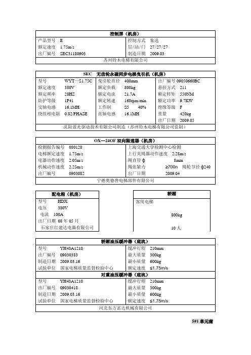
产品型号 E额定速度 1.75m/s出厂编号 SEC31180903 控制方式 集选 层/站/门 27/27/27 制造日期 2009.03苏州铃木电梯有限公司SEC 无齿轮永磁同步电梯曳引机(机房)型号 WYT —S1.75C 额定速度 380V 额定频率 28HZ 防护等级 1P41 交轴电感 16.1MH 绕组相电阻 0.82/PHASE曳引轮直径 400mm 额定负载 800kg 额定电流 21.7A额定转速 168rpm/min 工作制 S5 40% 直轴电感 16.1MH出厂编号09050660BC 悬挂方式 211 额定转矩 550NM 额定功率 9.7KW 绝缘等级 F 重量 420kg 出厂日期 2009.05沈阳蓝光驱动技术有限公司制造(苏州铃木电梯有限公司监制)OX —24OF 双向限速器(机房)检测报告编号 080128 电梯额定速度 1.75m/s 电器动作速度 2.05m/s 机械动作速度 2.25m/s 出厂编号 0903082 上海交通大学检测中心检测 上行夹绳器动作速度 2.28m/s 绳直径ф 8mm绳张紧力 ≥700n 绳轮节径ф240 出厂日期 2009.04宁德奥德普电梯部件有限公司配电箱(机房)型号 HDX 电压 380V 电流 100A出厂日期 08年05月石家庄红建达电器有限公司轿厢油压缓冲器(底坑)型号 YH43A1210 出厂编号 09030383 制造日期 2009.03.16试验单位 国家电梯质量监督检验中心 缓冲行程 210mm 最大质量 300kg 最小质量 600kg 额定速度 ≤1.75m/s 对重油压缓冲器(底坑)型号 YH43A1210 出厂编号 09030418 制造日期 2009.03.16试验单位 国家电梯质量监督检验中心 缓冲行程 210mm 最大质量 300kg 最小质量 600kg 额定速度 ≤1.75m/s河北东方富达机械有限公司5#1单元南轿厢客用电梯800kg10人产品型号 E额定速度 1.75m/s出厂编号 SEC31090903 控制方式 集选 层/站/门 27/27/27 制造日期 2009.03苏州铃木电梯有限公司SEC 无齿轮永磁同步电梯曳引机(机房)型号 WYT —S1.75C 额定速度 380V 额定频率 28HZ 防护等级 1P41 交轴电感 16.1MH 绕组相电阻 0.82/PHASE曳引轮直径 400mm 额定负载 800kg 额定电流 21.7A额定转速 168rpm/min 工作制 S5 40% 直轴电感 16.1MH出厂编号09050669BC 悬挂方式 211 额定转矩 550NM 额定功率 9.7KW 绝缘等级 F 重量 420kg 出厂日期 2009.05沈阳蓝光驱动技术有限公司制造(苏州铃木电梯有限公司监制)OX —24OF 双向限速器(机房)检测报告编号 080128 电梯额定速度 1.75m/s 电器动作速度 2.05m/s 机械动作速度 2.25m/s 出厂编号 不明 上海交通大学检测中心检测 上行夹绳器动作速度 2.28m/s 绳直径ф 8mm绳张紧力 ≥700n 绳轮节径ф240 出厂日期 2009.04宁德奥德普电梯部件有限公司配电箱(机房)型号 HDX 电压 380V 电流 100A出厂日期 08年05月石家庄红建达电器有限公司轿厢油压缓冲器(底坑)型号 YH43A1210 出厂编号 09030384 制造日期 2009.03.16试验单位 国家电梯质量监督检验中心 缓冲行程 210mm 最大质量 300kg 最小质量 600kg 额定速度 ≤1.75m/s 对重油压缓冲器(底坑)型号 YH43A1210 出厂编号 不明制造日期 2009.03.16试验单位 国家电梯质量监督检验中心 缓冲行程 210mm 最大质量 300kg 最小质量 600kg 额定速度 ≤1.75m/s河北东方富达机械有限公司5#1单元北轿厢客用电梯800kg10人产品型号 E额定速度 1.75m/s出厂编号 SEC31060903 控制方式 集选 层/站/门 27/27/27 制造日期 2009.03苏州铃木电梯有限公司SEC 无齿轮永磁同步电梯曳引机(机房)型号 WYT —S1.75C 额定速度 380V 额定频率 28HZ 防护等级 1P41 交轴电感 16.1MH 绕组相电阻 0.82/PHASE曳引轮直径 400mm 额定负载 800kg 额定电流 21.7A额定转速 168rpm/min 工作制 S5 40% 直轴电感 16.1MH出厂编号09050657BC 悬挂方式 211 额定转矩 550NM 额定功率 9.7KW 绝缘等级 F 重量 420kg 出厂日期 2009.05沈阳蓝光驱动技术有限公司制造(苏州铃木电梯有限公司监制)OX —24OF 双向限速器(机房)检测报告编号 080128 电梯额定速度 1.75m/s 电器动作速度 2.05m/s 机械动作速度 2.25m/s 出厂编号 不明 上海交通大学检测中心检测 上行夹绳器动作速度 2.28m/s 绳直径ф 8mm绳张紧力 ≥700n 绳轮节径ф240 出厂日期 2009.04宁德奥德普电梯部件有限公司配电箱(机房)型号 HDX 电压 380V 电流 100A出厂日期 08年05月石家庄红建达电器有限公司轿厢油压缓冲器(底坑)型号 YH43A1210 出厂编号 09030578 制造日期 2009.03.26试验单位 国家电梯质量监督检验中心 缓冲行程 210mm 最大质量 300kg 最小质量 600kg 额定速度 ≤1.75m/s 对重油压缓冲器(底坑)型号 YH43A1210 出厂编号 09030577 制造日期 2009.03.26试验单位 国家电梯质量监督检验中心缓冲行程 210mm 最大质量 300kg 最小质量 600kg 额定速度 ≤1.75m/s河北东方富达机械有限公司5#2单元南轿厢客用电梯800kg10人产品型号 E额定速度 1.75m/s出厂编号 SEC31070903 控制方式 集选 层/站/门 27/27/27 制造日期 2009.03苏州铃木电梯有限公司SEC 无齿轮永磁同步电梯曳引机(机房)型号 WYT —S1.75C 额定速度 380V 额定频率 28HZ 防护等级 1P41 交轴电感 16.1MH 绕组相电阻 0.82/PHASE曳引轮直径 400mm 额定负载 800kg 额定电流 21.7A额定转速 168rpm/min 工作制 S5 40% 直轴电感 16.1MH出厂编号09050658BC 悬挂方式 211 额定转矩 550NM 额定功率 9.7KW 绝缘等级 F 重量 420kg 出厂日期 2009.05沈阳蓝光驱动技术有限公司制造(苏州铃木电梯有限公司监制)OX —24OF 双向限速器(机房)检测报告编号 080128 电梯额定速度 1.75m/s 电器动作速度 2.05m/s 机械动作速度 2.25m/s 出厂编号 0904255 上海交通大学检测中心检测 上行夹绳器动作速度 2.28m/s 绳直径ф 8mm绳张紧力 ≥700n 绳轮节径ф240 出厂日期 2009.04宁德奥德普电梯部件有限公司配电箱(机房)型号 HDX 电压 380V 电流 100A出厂日期 08年05月石家庄红建达电器有限公司轿厢油压缓冲器(底坑)型号 YH43A1210 出厂编号 09030370 制造日期 2009.03.16试验单位 国家电梯质量监督检验中心 缓冲行程 210mm 最大质量 300kg 最小质量 600kg 额定速度 ≤1.75m/s 对重油压缓冲器(底坑)型号 YH43A1210 出厂编号 不明制造日期 2009.03.16试验单位 国家电梯质量监督检验中心缓冲行程 210mm 最大质量 300kg 最小质量 600kg 额定速度 ≤1.75m/s河北东方富达机械有限公司5#2单元北轿厢客用电梯800kg10人产品型号 E额定速度 1.75m/s出厂编号 SEC311040903 控制方式 集选 层/站/门 27/27/27 制造日期 2009.03苏州铃木电梯有限公司SEC 无齿轮永磁同步电梯曳引机(机房)型号 WYT —S1.75C 额定速度 380V 额定频率 28HZ 防护等级 1P41 交轴电感 16.1MH 绕组相电阻 0.82/PHASE曳引轮直径 400mm 额定负载 800kg 额定电流 21.7A额定转速 168rpm/min 工作制 S5 40% 直轴电感 16.1MH出厂编号09050655BC 悬挂方式 211 额定转矩 550NM 额定功率 9.7KW 绝缘等级 F 重量 420kg 出厂日期 2009.05沈阳蓝光驱动技术有限公司制造(苏州铃木电梯有限公司监制)OX —24OF 双向限速器(机房)检测报告编号 080128 电梯额定速度 1.75m/s 电器动作速度 2.05m/s 机械动作速度 2.25m/s 出厂编号 0904260 上海交通大学检测中心检测 上行夹绳器动作速度 2.28m/s 绳直径ф 8mm绳张紧力 ≥700n 绳轮节径ф240 出厂日期 2009.04宁德奥德普电梯部件有限公司配电箱(机房)型号 HDX 电压 380V 电流 100A出厂日期 08年05月石家庄红建达电器有限公司轿厢油压缓冲器(底坑)型号 YH43A1210 出厂编号 09030591 制造日期 2009.03.26试验单位 国家电梯质量监督检验中心 缓冲行程 210mm 最大质量 300kg 最小质量 600kg 额定速度 ≤1.75m/s 对重油压缓冲器(底坑)型号 YH43A1210 出厂编号 不明制造日期 2009.03.16试验单位 国家电梯质量监督检验中心 缓冲行程 210mm 最大质量 300kg 最小质量 600kg 额定速度 ≤1.75m/s河北东方富达机械有限公司6#1单元南轿厢客用电梯800kg10人产品型号 E额定速度 1.75m/s出厂编号 SEC311050903 控制方式 集选 层/站/门 27/27/27 制造日期 2009.03苏州铃木电梯有限公司SEC 无齿轮永磁同步电梯曳引机(机房)型号 WYT —S1.75C 额定速度 380V 额定频率 28HZ 防护等级 1P41 交轴电感 16.1MH 绕组相电阻 0.82/PHASE曳引轮直径 400mm 额定负载 800kg 额定电流 21.7A额定转速 168rpm/min 工作制 S5 40% 直轴电感 16.1MH出厂编号09050656BC 悬挂方式 211 额定转矩 550NM 额定功率 9.7KW 绝缘等级 F 重量 420kg 出厂日期 2009.05沈阳蓝光驱动技术有限公司制造(苏州铃木电梯有限公司监制)OX —24OF 双向限速器(机房)检测报告编号 080128 电梯额定速度 1.75m/s 电器动作速度 2.05m/s 机械动作速度 2.25m/s 出厂编号 不明 上海交通大学检测中心检测 上行夹绳器动作速度 2.28m/s 绳直径ф 8mm绳张紧力 ≥700n 绳轮节径ф240 出厂日期 2009.04宁德奥德普电梯部件有限公司配电箱(机房)型号 HDX 电压 380V 电流 100A出厂日期 08年05月石家庄红建达电器有限公司轿厢油压缓冲器(底坑)型号 YH43A1210 出厂编号 09030399 制造日期 2009.03.16试验单位 国家电梯质量监督检验中心 缓冲行程 210mm 最大质量 300kg 最小质量 600kg 额定速度 ≤1.75m/s 对重油压缓冲器(底坑)型号 YH43A1210 出厂编号 09030572 制造日期 2009.03.26试验单位 国家电梯质量监督检验中心 缓冲行程 210mm 最大质量 300kg 最小质量 600kg 额定速度 ≤1.75m/s河北东方富达机械有限公司6#1单元北轿厢客用电梯800kg10人产品型号 E额定速度 1.75m/s出厂编号 SEC311020903 控制方式 集选 层/站/门 27/27/27 制造日期 2009.03苏州铃木电梯有限公司SEC 无齿轮永磁同步电梯曳引机(机房)型号 WYT —S1.75C 额定速度 380V 额定频率 28HZ 防护等级 1P41 交轴电感 16.1MH 绕组相电阻 0.82/PHASE曳引轮直径 400mm 额定负载 800kg 额定电流 21.7A额定转速 168rpm/min 工作制 S5 40% 直轴电感 16.1MH出厂编号09050653BC 悬挂方式 211 额定转矩 550NM 额定功率 9.7KW 绝缘等级 F 重量 420kg 出厂日期 2009.05沈阳蓝光驱动技术有限公司制造(苏州铃木电梯有限公司监制)OX —24OF 双向限速器(机房)检测报告编号 080128 电梯额定速度 1.75m/s 电器动作速度 2.05m/s 机械动作速度 2.25m/s 出厂编号 不明 上海交通大学检测中心检测 上行夹绳器动作速度 2.28m/s 绳直径ф 8mm绳张紧力 ≥700n 绳轮节径ф240 出厂日期 2009.04宁德奥德普电梯部件有限公司配电箱(机房)型号 HDX 电压 380V 电流 100A出厂日期 08年05月石家庄红建达电器有限公司轿厢油压缓冲器(底坑)型号 YH43A1210 出厂编号 09030594 制造日期 2009.03.26试验单位 国家电梯质量监督检验中心 缓冲行程 210mm 最大质量 300kg 最小质量 600kg 额定速度 ≤1.75m/s 对重油压缓冲器(底坑)型号 YH43A1210 出厂编号 09030592 制造日期 2009.03.26试验单位 国家电梯质量监督检验中心 缓冲行程 210mm 最大质量 300kg 最小质量 600kg 额定速度 ≤1.75m/s河北东方富达机械有限公司6#2单元南轿厢客用电梯800kg10人产品型号 E额定速度 1.75m/s出厂编号 SEC311030903 控制方式 集选 层/站/门 27/27/27 制造日期 2009.03苏州铃木电梯有限公司SEC 无齿轮永磁同步电梯曳引机(机房)型号 WYT —S1.75C 额定速度 380V 额定频率 28HZ 防护等级 1P41 交轴电感 16.1MH 绕组相电阻 0.82/PHASE曳引轮直径 400mm 额定负载 800kg 额定电流 21.7A额定转速 168rpm/min 工作制 S5 40% 直轴电感 16.1MH出厂编号09050654BC 悬挂方式 211 额定转矩 550NM 额定功率 9.7KW 绝缘等级 F 重量 420kg 出厂日期 2009.05沈阳蓝光驱动技术有限公司制造(苏州铃木电梯有限公司监制)OX —24OF 双向限速器(机房)检测报告编号 080128 电梯额定速度 1.75m/s 电器动作速度 2.05m/s 机械动作速度 2.25m/s 出厂编号 0904252 上海交通大学检测中心检测 上行夹绳器动作速度 2.28m/s 绳直径ф 8mm绳张紧力 ≥700n 绳轮节径ф240 出厂日期 2009.04宁德奥德普电梯部件有限公司配电箱(机房)型号 HDX 电压 380V 电流 100A出厂日期 08年05月石家庄红建达电器有限公司轿厢油压缓冲器(底坑)型号 YH43A1210 出厂编号 09030400 制造日期 2009.03.16试验单位 国家电梯质量监督检验中心 缓冲行程 210mm 最大质量 300kg 最小质量 600kg 额定速度 ≤1.75m/s 对重油压缓冲器(底坑)型号 YH43A1210 出厂编号 09030593 制造日期 2009.03.26试验单位 国家电梯质量监督检验中心 缓冲行程 210mm 最大质量 300kg 最小质量 600kg 额定速度 ≤1.75m/s河北东方富达机械有限公司6#2单元北轿厢客用电梯800kg10人产品型号 E额定速度 1.75m/s出厂编号 SEC31100903 控制方式 集选 层/站/门 27/27/27 制造日期 2009.03苏州铃木电梯有限公司SEC 无齿轮永磁同步电梯曳引机(机房)型号 WYT —S1.75C 额定速度 380V 额定频率 28HZ 防护等级 1P41 交轴电感 16.1MH 绕组相电阻 0.82/PHASE曳引轮直径 400mm 额定负载 800kg 额定电流 21.7A额定转速 168rpm/min 工作制 S5 40% 直轴电感 16.1MH出厂编号09050661BC 悬挂方式 211 额定转矩 550NM 额定功率 9.7KW 绝缘等级 F 重量 420kg 出厂日期 2009.05沈阳蓝光驱动技术有限公司制造(苏州铃木电梯有限公司监制)OX —24OF 双向限速器(机房)检测报告编号 080128 电梯额定速度 1.75m/s 电器动作速度 2.05m/s 机械动作速度 2.25m/s 出厂编号 不明 上海交通大学检测中心检测 上行夹绳器动作速度 2.28m/s 绳直径ф 8mm绳张紧力 ≥700n 绳轮节径ф240 出厂日期 2009.04宁德奥德普电梯部件有限公司配电箱(机房)型号 HDX 电压 380V 电流 100A出厂日期 09年06月石家庄红建达电器有限公司轿厢油压缓冲器(底坑)型号 YH43A1210 出厂编号 09030431 制造日期 2009.03.16试验单位 国家电梯质量监督检验中心 缓冲行程 210mm 最大质量 300kg 最小质量 600kg 额定速度 ≤1.75m/s 对重油压缓冲器(底坑)型号 YH43A1210 出厂编号 09030432 制造日期 2009.03.16试验单位 国家电梯质量监督检验中心 缓冲行程 210mm 最大质量 300kg 最小质量 600kg 额定速度 ≤1.75m/s河北东方富达机械有限公司7#3单元南轿厢客用电梯800kg10人产品型号 E额定速度 1.75m/s出厂编号 SEC31110903 控制方式 集选 层/站/门 27/27/27 制造日期 2009.03苏州铃木电梯有限公司SEC 无齿轮永磁同步电梯曳引机(机房)型号 WYT —S1.75C 额定速度 380V 额定频率 28HZ 防护等级 1P41 交轴电感 16.1MH 绕组相电阻 0.82/PHASE曳引轮直径 400mm 额定负载 800kg 额定电流 21.7A额定转速 168rpm/min 工作制 S5 40% 直轴电感 16.1MH出厂编号09050662BC 悬挂方式 211 额定转矩 550NM 额定功率 9.7KW 绝缘等级 F 重量 420kg 出厂日期 2009.05沈阳蓝光驱动技术有限公司制造(苏州铃木电梯有限公司监制)OX —24OF 双向限速器(机房)检测报告编号 080128 电梯额定速度 1.75m/s 电器动作速度 2.05m/s 机械动作速度 2.25m/s 出厂编号 不明 上海交通大学检测中心检测 上行夹绳器动作速度 2.28m/s 绳直径ф 8mm绳张紧力 ≥700n 绳轮节径ф240 出厂日期 2009.04宁德奥德普电梯部件有限公司配电箱(机房)型号 HDX 电压 380V 电流 100A出厂日期 09年06月石家庄红建达电器有限公司轿厢油压缓冲器(底坑)型号 YH43A1210 出厂编号 09030425 制造日期 2009.03.16试验单位 国家电梯质量监督检验中心 缓冲行程 210mm 最大质量 300kg 最小质量 600kg 额定速度 ≤1.75m/s 对重油压缓冲器(底坑)型号 YH43A1210 出厂编号 09030426 制造日期 2009.03.16试验单位 国家电梯质量监督检验中心 缓冲行程 210mm 最大质量 300kg 最小质量 600kg 额定速度 ≤1.75m/s河北东方富达机械有限公司7#3单元北轿厢客用电梯800kg10人产品型号 E额定速度 1.75m/s出厂编号 SEC31120903 控制方式 集选 层/站/门 27/27/27 制造日期 2009.03苏州铃木电梯有限公司SEC 无齿轮永磁同步电梯曳引机(机房)型号 WYT —S1.75C 额定速度 380V 额定频率 28HZ 防护等级 1P41 交轴电感 16.1MH 绕组相电阻 0.82/PHASE曳引轮直径 400mm 额定负载 800kg 额定电流 21.7A额定转速 168rpm/min 工作制 S5 40% 直轴电感 16.1MH出厂编号09050663BC 悬挂方式 211 额定转矩 550NM 额定功率 9.7KW 绝缘等级 F 重量 420kg 出厂日期 2009.05沈阳蓝光驱动技术有限公司制造(苏州铃木电梯有限公司监制)OX —24OF 双向限速器(机房)检测报告编号 080128 电梯额定速度 1.75m/s 电器动作速度 2.05m/s 机械动作速度 2.25m/s 出厂编号 不明 上海交通大学检测中心检测 上行夹绳器动作速度 2.28m/s 绳直径ф 8mm绳张紧力 ≥700n 绳轮节径ф240 出厂日期 2009.04宁德奥德普电梯部件有限公司配电箱(机房)型号 HDX 电压 380V 电流 100A出厂日期 09年06月石家庄红建达电器有限公司轿厢油压缓冲器(底坑)型号 YH43A1210 出厂编号 09030436 制造日期 2009.03.16试验单位 国家电梯质量监督检验中心 缓冲行程 210mm 最大质量 300kg 最小质量 600kg 额定速度 ≤1.75m/s 对重油压缓冲器(底坑)型号 YH43A1210 出厂编号 09030435 制造日期 2009.03.16试验单位 国家电梯质量监督检验中心 缓冲行程 210mm 最大质量 300kg 最小质量 600kg 额定速度 ≤1.75m/s河北东方富达机械有限公司7#4单元南轿厢客用电梯800kg10人产品型号 E额定速度 1.75m/s出厂编号 SEC31130903 控制方式 集选 层/站/门 27/27/27 制造日期 2009.03苏州铃木电梯有限公司SEC 无齿轮永磁同步电梯曳引机(机房)型号 WYT —S1.75C 额定速度 380V 额定频率 28HZ 防护等级 1P41 交轴电感 16.1MH 绕组相电阻 0.82/PHASE曳引轮直径 400mm 额定负载 800kg 额定电流 21.7A额定转速 168rpm/min 工作制 S5 40% 直轴电感 16.1MH出厂编号09050664BC 悬挂方式 211 额定转矩 550NM 额定功率 9.7KW 绝缘等级 F 重量 420kg 出厂日期 2009.05沈阳蓝光驱动技术有限公司制造(苏州铃木电梯有限公司监制)OX —24OF 双向限速器(机房)检测报告编号 080128 电梯额定速度 1.75m/s 电器动作速度 2.05m/s 机械动作速度 2.25m/s 出厂编号 0904263 上海交通大学检测中心检测 上行夹绳器动作速度 2.28m/s 绳直径ф 8mm绳张紧力 ≥700n 绳轮节径ф240 出厂日期 2009.04宁德奥德普电梯部件有限公司配电箱(机房)型号 HDX 电压 380V 电流 100A出厂日期 09年06月石家庄红建达电器有限公司轿厢油压缓冲器(底坑)型号 YH42A1160 最大允许总重量 3000kg 最小允许总重量 600kg试验单位 国家电梯质量监督检验中心 额定速度 ≤1.5m/s 缓冲行程 160mm 制造日期 20081126 产品编号 08110280 对重油压缓冲器(底坑)型号 YH42A1160 最大允许总重量 3000kg 最小允许总重量 600kg试验单位 国家电梯质量监督检验中心 额定速度 ≤1.5m/s 缓冲行程 160mm 制造日期 20081126 产品编号 08110281河北东方机械厂制造7#4单元北轿厢客用电梯800kg10人。
自由系列NEMA接触器——产品概述说明书

Freedom Series NEMA Contactors – Overview• Market leader in NEMA power control • Most complete line in the industry• Ideal for project construction, HVAC, pump and industrial applications • Open and enclosed versionsType CN15/CN55 NEMA Contactors – Model SelectionNEMA Size Continuous Ampere Rating Maximum UL Horsepower 3-Pole Non-Reversing 3-Pole Reversing 1-Phase 3-Phase 115V 230V 208V 240V 480V 600V Catalog Number 1Catalog Number 10091/311-1/21-1/222CN15AN3_B CN55AN3_B 018123355CN15BN3_B CN55BN3_B 127237-1/27-1/21010CN15DN3_B CN55DN3_B 24537-1/210152525CN15GN3_B CN55GN3_B 390––25305050CN15KN3_CN55KN3_4135––4050100100CN15NN3_CN55NN3_5270––75100200200CN15SN3_CN55SN3_6540––150200400400CN15TN3_B CN55TN3_B 7810––200300600600CN15UN3_CN55UN3_821215––400450900900CN15VN3_CN55VN3_1 When ordering, replace magnet coil alpha designation in catalog number (_) with proper code suffi x from table below.2Common control. For separate 120V control, insert letter D in seventh position of listed catalog number (ex. CN15VND3C).Magnet Coils (AC and DC) – Model SelectionCoil Volts and Hertz Code Suffi x Coil Volts and Hertz Code Suffi x 120/60, 110/50240/60, 220/50480/60, 440/50600/60, 550/50A B C D 380-415/50550/5024/60, 24/50 424/50L N T U 208/60277/60208-240/60 3240/50E H J K32/5048/6048/50V W Y3 NEMA Sizes 00 and 0 only.4NEMA Sizes 00 and 0 only. Sizes 1 through 8 are 24/60 only.NEMA Contactors forthe Construction MarketNEMA Size 1 ContactorAuxiliary Contacts – Model SelectionSide-Mounted, NEMA Sizes 00 to 2, IEC Sizes A to K Description Contact Confi guration Code 5Catalog Number 1NO 1NC1001C320KGS1C320KGS21NO-1NC 2NO 2NC1NO-1NCI1NO (EC) - 1NC (LO)1NCI112002N/A N/A N/AC320KGS3C320KGS4C320KGS5C320KGS6C320KGS7C320KGS85This two-digit code is found on the auxiliary contact to assist in identifying the specifi c contact confi guration. The fi rst digit indicates the quantity of NO contacts and the second indicates the quantity of NC contacts.Additional Freedom Series auxiliary contacts are available. For a complete listing of theseaccessories, see the Control Products & Services Catalog (CA08102001E), Tab 33.Eaton Corporation Electrical Group1000 Cherrington Parkway Moon Township, PA 15108United States877-ETN-CARE (877-386-2273)© 2009 Eaton Corporation All Rights ReservedPublication No. TD03301007EApril 2009PowerChain Management is a registered trademark of Eaton Corporation. All other trademarks are property of their respective owners.Quick Selector TD03301007EApril 2009NEMA Contactors for the Construction MarketFreedom Series NEMA Starters – Overview• Three-phase, full voltage magnetic starters most commonly used to switch ACmotor loads • Bimetallic ambient compensated overload relays • These overload relays feature:• Interchangeable heater packs adjustable ±24% to match motor FLA • Selectable manual or automatic reset operation• Single-phase protection, Class 20 or Class 10 trip time • Overload trip indication•Electrically isolated NO-NC contacts (pull RESET button to test)• Also available with solid-state overload relays (see T ab 33 of the Control Products & Services Catalog, CA08102001E)Type AN16/An56 NEMA Starters – Model SelectionNEMA Size Continuous Ampere Rating Service-Limit Current Ratings 2Maximum UL Horsepower3-Pole Non-Reversing 3-Pole Reversing Vertical Reversing 1-Phase 3-Phase 115V 230V 208V 240V 480V 600V Catalog Number 1Catalog Number 1Catalog Number 1009111/311-1/21-1/222AN16AN0_C AN56AN0_C –01821123355AN16BN0_C An56BN0_C AN56BNV0_12732237-1/27-1/21010AN16DN0_B AN56DN0_B AN56DNV0_2455237-1/210152525AN16GN0_B AN56GN0_B AN56GNV0_390104––25305050AN16KN0_AN56KN0_AN56KNV0_4135156––4050100100AN16NN0_AN56NN0_AN56NNV0_5270311––75100200200AN16SN0_B AN56SN0_B –6540621––150200400400AN16TN0_C AN56TN0_B –7810932––200300600600AN16UN0_B AN56UN0_B –8312151400––400450900900AN16VN0_BAN56VN0_B–1 When ordering, replace magnet coil alpha designation in catalog number (_) with proper code suffi x from table below.2The service-limit current ratings represent the maximum RMS current, in amperes, which the controller shall be permitted to carry for protracted periods in normal service. At service-limit current ratings, termperature rises shall be permitted to exceed those obtained by testing the controller at its continuous current rating. The current rating of overload relays or trip current of other motor protective devices used shall not exceed the service-limit current rating of the controller.3Common control. For separate 120V control, insert letter D in seventh position of listed catalog number (ex. CN15VND3C).Magnet Coils (AC and DC) – Model SelectionCoil Volts and Hertz Code Suffi x Coil Volts and Hertz Code Suffi x 120/60, 110/50240/60, 220/50480/60, 440/50600/60, 550/50A B C D 380-415/50550/5024/60, 24/50 524/50L N T U 208/60277/60208-240/60 4240/50E H J K32/5048/6048/50V W Y4 NEMA Sizes 00 and 0 only.5NEMA Sizes 00 and 0 only. Sizes 1 through 8 are 24/60 only.Freedom Series Non-Reversing StarterNEMA Size 1Freedom Series Reversing StarterNEMA Size 1Freedom Series Auxiliary ContactsAuxiliary Contacts – Model SelectionSide-Mounted, NEMA Sizes 00 to 2, IEC Sizes A to K Description Contact Confi guration Code 6Catalog Number 1NO 1NC1001C320KGS1C320KGS21NO-1NC 2NO 2NC1NO-1NCI1NO (EC) - 1NC (LO)1NCI112002N/A N/A N/AC320KGS3C320KGS4C320KGS5C320KGS6C320KGS7C320KGS86This two-digit code is found on the auxiliary contact to assist in identifying the specifi c contact confi guration. The fi rst digit indicates the quantity of NO contacts and the second indicates the quantity of NC contacts.Additional Freedom Series auxiliary contacts are available inNEMA sizes 3 to 8 and IEC sizes L to Z. For a complete listing of these accessories, see the Control Products & Services Catalog (CA08102001E), Tab 33.。
英鹤观光车参数配置表
英鹤观光车参数配置表摘要:一、英鹤观光车简介二、英鹤观光车参数配置表1.发动机参数2.底盘参数3.车身参数4.电气设备参数5.车内设施参数三、英鹤观光车的优势与特点四、英鹤观光车的应用场景五、结语正文:【一、英鹤观光车简介】英鹤观光车是一款集舒适性、安全性和环保性于一体的旅游观光专用车辆。
它采用进口发动机,具有良好的动力性能和低噪音、低排放的特点,为游客提供了一个舒适的旅游环境。
同时,英鹤观光车还具备较高的底盘和良好的通过性能,适应各种路况,满足不同景区的观光需求。
【二、英鹤观光车参数配置表】【1.发动机参数】英鹤观光车搭载进口发动机,提供充足的动力输出,确保车辆在各种路况下都能保持稳定的行驶速度。
此外,发动机还具有高效能、低油耗的特点,既节约能源,又降低运营成本。
【2.底盘参数】英鹤观光车采用高强度钢制底盘,具有较高的抗弯曲和抗扭曲性能,保证车辆在行驶过程中的稳定性和安全性。
同时,车辆还配备了独立悬挂系统,有效缓解行驶中的震动,提高乘坐舒适度。
【3.车身参数】英鹤观光车的车身采用优质不锈钢材料制造,具有良好的耐腐蚀性和抗氧化性,确保车辆长期使用仍能保持光亮如新。
车身尺寸根据不同车型和座位数进行设计,满足不同景区的运营需求。
【4.电气设备参数】英鹤观光车配备先进的电气系统,具有过载保护、短路保护等功能,确保车辆电气设备的安全稳定运行。
此外,车辆还配备了行车记录仪、倒车影像等辅助驾驶设备,提高驾驶安全性。
【5.车内设施参数】英鹤观光车内饰采用高级材料,注重乘坐舒适性。
车辆配备了空调、音响等娱乐设施,为游客提供舒适的旅游环境。
同时,车辆还根据实际需求配备了行李架、残疾人辅助设施等,方便游客出行。
【三、英鹤观光车的优势与特点】英鹤观光车凭借其出色的性能、舒适的乘坐体验和稳定的运行质量,在旅游观光行业中具有较高的口碑。
车辆采用环保型发动机,降低排放,实现绿色出行。
此外,英鹤观光车还具有较高的性价比,为景区和游客带来实惠。
5R55N-_5R55S-_5R55W

011H 5R55N (Plastic) (0.4” Pickup Tube)........................................................................... 1 99-Up 46011 011H 5R55S (Metal/Plastic) (1.3” Pickup Tube) (Car)......................................................... 1 03-Up 46011B 011H 5R55S/W (Metal/Plastic) (2.4” Pickup Tube) (SUV).................................................... 1 02-Up 46011A
H
46
195
FORD 5R55N, 5R55S, 5R55W
46300W
46010
46010A 46010B
5R55N (99-Up)
Lincoln LS Jaguar X200
5R55W/S (02-Up)
Explorer
ill.
DESCRIPTION
QTY. YEAR
PART NO.
DELUXE KITS (SUPER KITS)
5R55N
5R55N
FORD 5R55N, 5R55S, 5R55W
F
G
Deluxe Kit---------------------------------- 008 Compliance Kit------------------------- 007 Master Kit -------------------------------- 006 Less Steel Kit--------------------------- 004 Overhaul Kit ----------------------------- 002 Bushing Kit ------------------------------- 030 Washer Kit -------------------------------- 200 Bearing Kit ------------------------------- 201 Technical Manual ------------------ 400 Pump Part---------------------------------- 507 Valve Body Parts -------------------- 741 Case Parts ------------------------------- 761 Note: Not all items are available for all transmissions
有关马哈公司48寸转鼓的技术说明

DIN EN ISO 9001关于马哈公司48寸转鼓的技术特点说明1.附加损耗的补偿:转鼓自身的附加损耗(也称寄生阻力)由两个因素组成:A. 转鼓轴承摩擦阻力;B. 风的阻力。
为了提高检测精度,要将这两项指标确定并加以补偿。
而这项工作是汽车排放检验和性能检验过程中非常重要的一个环节。
马哈公司的转鼓通过以下两个方式将附加损耗进行补偿。
1)轴承摩擦损耗补偿;2)风阻损耗补偿。
马哈公司使用这两项技术可以使附加损耗补偿精度作到低于2,5N@100kph2. 附加损耗的确定:如何确定转鼓的附加损耗是检测过程中非常重要的因素。
下图是MAHA公司生产的四驱转鼓确定附加损耗的一个检测软件显示:其中,蓝色表示为前滚筒黄色表示为后滚筒滚筒速度为零时,附加损耗也为零。
此时轴承摩擦阻力小得几乎可以忽略不计。
而滚筒转速达到100KPH时,附加损耗逐渐上升为12N,这是因为滚筒在转动过程中风阻加大了。
正确地确定附加损耗的数值并加以补偿,给我们精确地检测车辆创造了一个非常稳定和重复性很高的工作环境。
为了避免轴承在一个方向长期受压,MAHA公司使用了特殊技术由电机驱动轴承向两个方向慢速转动。
通过这种方法,轴承受力非常均匀。
这样既保证了轴承的使用寿命,又为用户提供了无需预热就可以进行试验的可能性。
因此,MAHA生产的转鼓附加损耗数值非常稳定。
图中可以看到,转速在80KPH时,数值一直保持在9N不变。
随机提供的软件可以帮助用户证实和确定附加阻力的大小)。
此技术参数是否稳定是判定一个四驱排放转鼓是否可信的一个重要标准。
(图)DIN EN ISO 90013. 转鼓的同步性当前世界汽车飞速发展。
越来越多的汽车装备了全时四驱、ASR、EPS等许多电子控制系统。
这些系统的转速信号都以毫秒计算。
因此,四驱转鼓的前后两套转鼓需要有极高的同步性。
否则会影响到汽车排放检测的精度。
令人无法确认原因到底是什么。
马哈公司发明的专利技术确保了其四驱转鼓同步性稳列世界第一的位置。
HT48R05A-1中文资料
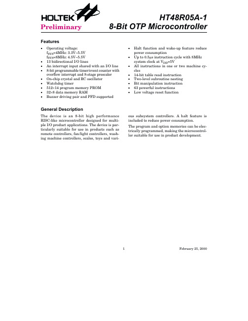
· Halt function and wake-up feature reduce power consumption
· Up to 0.5ms instruction cycle with 8MHz system clock at VDD=5V
· All instructions in one or two machine cycles
3.3V
¾
¾
5
mA
No load, system Halt
5V
¾
¾
10
mA
ISTB2
Standby Current (WDT Disabled)
3.3V
¾
¾
No load, system Halt
5V
¾
¾
1
mA
2
mA
VIL1
Input Low Voltage for 3.3V I/O ports, TMR and INT 5V
mA
4
mA
IDD2
Operating Current (RC OSC)
3.3V
¾
No load, fSYS=4MHz
5V
¾
1 2
2
mA
4
mA
IDD3
Operating Current (Crystal OSC)
5V No load, fSYS=8MHz
¾
5
10 mA
ISTB1
Standby Current (WDT Enabled)
The device is an 8-bit high performance RISC-like microcontroller designed for multiple I/O product applications. The device is particularly suitable for use in products such as remote controllers, fan/light controllers, washing machine controllers, scales, toys and vari-
DIO-48 产品说明书
Language English Version V1.3 UpdateJun.2009……………………………………………… What’s in your package?¾ One DIO-48 series card¾ One companion ISA CD (V2.1 or later) ¾ One Quick Start Guide (This document)……………………………………………… Installing Windows DriverFollow these steps:1. Setup the Windows driver. The driver is location at: CD:\NAPDOS\ISA\DIO\DLL\/pub/cd/iocard/isa/napdos/isa/dio/dll/12DIO-482. Click the button to start the installation.3. Click the button to install the driver into the default folder.4. Click the button to continue the installation.5. Select the “NO, I will restart my computer later” and thenclick thebutton.……………………………………………… I/O Base Address & Interrupt Setting¾ The base address is set from SW1 DIP switch on board: (Default setting for 2C0)¾ Interrupt jumper setting3I/O Address1 A92 A83 A74 A65 A56A4200-20F Off On On On On On 210-21F Off On On On On Off…..2C0-2CF(Default) Off On Off Off On On……..3F0-3FF Off Off Off Off Off OffBASE ADDRESS A9 A8 A7 A6 A5 A4 Default DIP switch settingDefault IRQ3 4 5 6 79 1011 121415NC……………………………………………… Installing Hardware on PCFollow these steps:1. Shut down and power off your computer.2. Remove the cover from the computer.3. Select an unused ISA slot.4. Carefully insert your I/O card into the ISA slot.5. Replace the PC cover.6. Power on the computer.After powering-on the computer, continue next process.……………………………………………… Adding Hardware7. Add Hardware7-1 Open the“Control Panel” by click the item “Start / Settings /Control Panel”.7-2 Double-click the item “Add/Remove Hardware” and Click the“Next >” button .7-3 Select the item “Add/Troubleshoot a device” and click the“Next >” button.7-4 Select the item “Add a new device” and click the “Next >”button.47-5 Select the item “No, I want to select the hardware from a list”and click the “Next >” button.7-6 Select the item “Other device” and click the “Next >” button. 7-7 Click the “Have Disk…” button. 7-8 Click the “Browse…” button to select the Inf file default path isC:\DAQPRO\DIO_Win2K\Inf and click the “OK” button.7-9 Select the correct device from the “Models:” listbox and Clickthe “Next >” button. 7-10 The windows show to dialog box and Click the “OK” button toenter the device’s properties settings.8. Modify the device properties.9. Reboot the PCThe detail “add hardware” information. Please refer toCD:\NAPDOS\ISA\Manual\PCI_ISA_PnP_Driver_Installation_in_Win9x_2K_XP .pdf/pub/cd/iocard/isa/napdos/isa/manual/pci_isa_pnp_driver_installation_in_win9x_2k_xp.pdfNo devices are conflicting¾ CH1 and CH2 pin assignment.1. Use the CA-5002(Optional) to connect CN1 to CN2.2. Execute the DIO-48 sample program.Get the file from (Default path):C:\DAQPro\DIO_WinXXX\Demo\CA-50023. Get DIO function test result.……………………………………………… Additional Information9 DIO-48 Series Card Product page:/products/DAQ/pc_based/dio_48.htm9 CA-5002(Optional) page:/products/Accessories/cable/cable_selection.htm9 Documentation:CD:\NAPDOS\ISA\DIO\manual/pub/cd/iocard/isa/napdos/isa/dio/manual/9 Software:CD:\NAPDOS\ISA\DIO/download/isa/dio/index.htmThe ICP DAS Web SiteContact Us******************Copyright ©2009 by ICP DAS Co., Ltd. All rights are reserved8。
CW48中文资料

125A
CWD48125 CWA48125 CWA48125E
AVAILABLE OPTIONS
OUTPUT SPECIFICATIONS (1)
Description
Operating Voltage (47-63Hz) [Vrms] (8) Transient Overvoltage [Vpk] Maximum Off-State Leakage Current @ Rated Voltage [mArms](6) Minimum Off-State dv/dt @ Maximum Rated Voltage [V/µsec] (2) Maximum Load Current (3) [Arms] Minimum Load Current [Arms] Maximum Surge Current (16.6ms) [Apk] Maximum Surge Current (20ms) [Apk] Maximum On-State Voltage Drop @ Rated Current [Vpk] Thermal Resistance Junction to Case (Rjc) [°C/W] Maximum I²t for Fusing (8.3 msec) [A²sec] Minimum Power Factor (with Maximum Load)
GENERAL SPECIFICATIONS
Description
Dielectric Strength, Input/Output/Base (50/60Hz) Minimum Insulation Resistance (@ 500 V DC) Maximum Capacitance, Input/Output Ambient Operating Temperature Range Ambient Storage Temperature Range Weight (typical) Encapsulation Terminals Max. Torque Max. Wire Size
海风差速锁产品型号及应用车型

温岭市海风差速器有限公司弹簧NissanVehicle/ Model AxleLoc'n Year Description ShaftDiameterShaftSplineRatio OFF-ROADPart No.Nissan Y60,Y61Front升高3英寸弹簧HF412 Rear 升高3英寸弹簧HF415Final reduction gear盆骨齿Vehicle/ Model AxleLoc'n Year Description ShaftDiameterShaftSplineRatio OFF-ROADPart No.Suzuki Front Final reduction gear(盆骨齿)10 bolt RG4.625 HFCS837-10-leftFront Final reduction gear(盆骨齿)8 bolt RG4.625 HFCS837-8-leftRear Final reduction gear(盆骨齿)10 bolt RG4.625 HFCS837-10-right海风差速锁产品型号及应用车型Mitsubishi(三菱)Nissan(日产)HoldenISUZU(五十铃)Suzuki(铃木)SantanaDodge(道奇)SsangYong(双龙)Ford(福特)Land Rover(路虎)Mazda(马自达)Hyundai(现代)UAZ国产切诺基牧马人三菱陆霸中兴长城系列郑州日产Roewe(荣威)Hyundai(现代)KIAChrysler or Jeep(克莱斯勒、北京JEEP)黄海福田曙光(黄海)双环华泰奇瑞角斗士Mitsubishi(三菱)APPLICATIONS BY PART NUMBERARB Part No. Description Splines Ratio Superseded Part #(s) RD01(RD132) Toyota8”,45mm carrier bearing 30 AllRD02(RD142) Toyota8 7/8”,45mm carrier bearing 30 AllRD03(RD127) Land Rover,10 SPL,Banjo 10 3.54RD04(RD134) Nissan,H233,31 SPL(thrust block) 31 AllRD05 Mitsubishi 8",RR,28 SPL 28 All RD210RD06(RD116) Dana 44,30 SPL,3.92&UP 30 3.92&UPRD07(RD117) Dana 44,30 SPL,3.73&DN 30 3.73&DNRD08(RD153) Toyota8 7/8”,C-clip 30 AllRD09(RD136) Nissan,H233B,31 SPL 31 AllRD17(RD135) Nissan,H233B,33 SPL,disc brake 33 AllRD20(RD161) Land Rover,Salisbury,3.54:1 24 3.54RD21(RD162) Dana 60,30 SPL,4.56 & UP 30 4.56 & UPRD22(RD163) Dana 60,30 SPL,4.10 & DN 30 4.10 & DNRD23(RD132) Toyota8”,50mm carrier bearing 30 AllRD24(RD135) Nissan,H233B,33 SPL,drum brake 33 AllRD25(RD46) Mitsubishi Montero,RR(large),dics brake 28 AllRD27(RD107) Nissan C200,29 SPL 29 AllRD32(RD160) Land Rover,Salisbury,4.70:1 24 4.7RD33(RD142) Toyota8 7/8”,50mm carrier bearing 30 AllRD35(RD166) Dana 60HD,35 SPL,4.56&UP 35 4.56&UPRD36(RD167) Dana 60HD,35 SPL,4.10&DN 35 4.10&DNRD42(RD168) Dana 60HD,C-clip,35 SPL,4.56 & UP 35 4.56 & UPRD43(RD163) Dana 60HD,C-clip,35 SPL,4.10 & DN 35 4.10 & DNRD44 Isuzu,RR,26SPL 26 All RD213RD46 Mitsubishi 9",RR,28 SPL 28 All RD212RD56(RD128) Land Rover,24 SPL,Banjo 24 AllRD57(RD138) Land Rover,24 SPL,Banjo,T/C 24 AllRD72(RD208) Suzuki 26 SPL,10 bolt RG 26 AllRD74(RD204) Suzuki Sidekick,RR,26 SPL,10bolt RG 26 AllRD75 Suzuki Sidekick,FR,22 SPL 22 All RD205RD78A(RD136) Nissan,H233B,FR,31 SPL 31 AllRD79(RD209) Suzuki Vitara,RR,26 SPL,12 bolt RG 26 AllRD87(RD207) Suzuki Jimny, FR,22 SPL 22 AllRD88(RD208) Suzuki Sidekick,FR,26 SPL 26 AllRD90 Toyota 7.5" IFS 27 AllRD93 Chrysler 8.25",29 SPL 29 AllRD95(RD164) Dana 60,32 SPL,4.56 &UP 32 4.56 &UPRD96(RD165) Dana 60,32 SPL,4.10 &DN 32 4.10 &DNRD100 Dana 30,27 SPL,3.73 & UP 27 3.73& UP RD30RD100-1 Roewe W5,27 SPL,3.73 & UP 27 3.73& UPRD101 Dana 30,27 SPL,3.54 & DN 27 3.54&DN RD31RD102 Dana 35,27 SPL,3.54 & UP 27 3.54& UP RD49,RD59,RD69 RD103 Dana 35,27 SPL,3.31 & DN 27 3.31&DN RD48,RD58,RD68 RD104 Dana 30,30SPL,3.73 & UP 30 3.73 & UPRD105 Dana 35,30 SPL,3.54 & UP 30 3.54 & UPRD107 Nissan C200/R200A,29 SPL 29 AllRD109 Dana 44,35SPL,3.92& UP 35 3.92& UPRD110 Mitsubishi IFS,28 SPL 28 AllRD111 Toyota 8” IFS,53mm BRNG 30 3.91 & UPRD112 Chrysler 8.25”,27 SPL 27 AllRD116 Dana 44,30 SPL,3.92 & UP 30 3.92& UP RD06RD117 Dana 44,30 SPL,3.73 & DN 30 3.73&DN RD07RD117-1 Roewe W5,30 SPL,3.73 & DN 30 3.73&DNRD118(RD206) Suzuki Jimny, FR,22 SPL,10 bolt RG 22 AllRD119 Ford 9”,31 SPL 31 AllRD121 Toyota 8" IFS,53mm BRNG 30 3.73&DNRD124(RD153) Toyota 8.9”,C-clip,50mm BRNG 30 AllRD128 Land Rover,24 SPL,Banjo 24 All RD56RD132 Toyota 8",50mm BRNG 30 All RD01,RD23RD134 Nissan H233,31 SPL 31 All RD04RD135 Nissan H233B,33 SPL 33 All RD17,RD24RD136 Nissan H233B,31 SPL 31 All RD09,RD78,RD78A RD138 Land Rover,24 SPL,Banjo,P38A 24 All RD57RD142 Toyota 8.9",50mm BRNG 30 All RD02,RD33RD143 Dana 44,32SPL,3.73&DN 32 3.73&DNRD147 Dana 44,35SPL,3.73&DN 35 3.73&DNRD152 Toyota 9.5”,32SPL 32 AllRD153 Toyota 8.9",C-clip,50mm BRNG 30 All RD08,RD124RD154 Mitsubishi 9.5",31 SPL,LIVE AXLE 31 AllRD155 Mitsubishi 9.5",33 SPL,IRS 33 AllRD156 Hyundai 9.5",34 SPL,LIVE AXLE 34 AllRD160 Land Rover,Salisbury,4.70:1 24 4.7 RD32RD161 Land Rover,Salisbury,3.54:1 24 3.54 RD20RD162 Dana 60,30SPL,4.56&UP 30 4.56&UP RD21RD163 Dana 60,30SPL,4.10&DN 30 4.10&DN RD22RD164 Dana 60,32SPL,4.56&UP 32 4.56&UP RD95RD165 Dana 60,32SPL,4.10&DN 32 4.10&DN RD96RD166 Dana 60HD,35 SPL,4.56 & UP 35 4.56& UP RD35RD167 Dana 60HD,35 SPL,4.10 & DN 35 4.10&DN RD36RD168 Dana 60HD,C-clip,35 SPL,4.56 & UP 35 4.56& UP RD42RD169 Dana 60HD,C-clip,35 SPL,4.10 & DN 35 4.10&DN RD43RD193 Toyota 8.25" RR,12 Bolt RG,shim adjusted 30 AllRD201 Nissan C200,31 SPL 31 All Rd106RD202 Nissan C200/R200A,29 SPL 29 All RD27,RD107 RD203 Isuzu IFS,17 SPL 17 All RD94RD204 Suzuki Vitara,RR,26 SPL,10 bolt RG 26 All RD74RD205 Suzuki,FR,22 SPL,10 bolt RG 22 All RD73,RD75 RD206 Suzuki Jimny,FR,22 SPL,10 bolt RG 22 All RD118RD207 Suzuki Jimny,FR,22 SPL,8 bolt RG 22 All RD77,RD87 RD208 Suzuki,26 SPL,10 bolt RG 26 All RD72,RD88 RD209 Suzuki Vitara,RR,26 SPL,12 bolt RG 26 All RD79RD210 Mitsubishi 8",RR,28 SPL 28 All RD05RD212 Mitsubishi 9",RR,28 SPL 28 All RD46RD213 Isuzu,RR,26 SPL 26 All RD44Wenling Hai FengGENERAL NOTES:While every effort has been made to ensure TBD ' refers to information that is still yet 'To Be Determined' at the time this list was last updated.that this list is accurate, Wenling Hai Feng Corporation Ltd. & UP' following the ratio means that the Air Locker is suitable for thestated ratio and thosecannot possibly guarantee its accuracy or which are numerically higher.completeness given the large number of vehicle & DN ' following the ratio means that the Air Locker is suitable for the stated ratio and t hosemakes, models, and option variations, and which are numerically lower.therefore it is the client's responsibility to RG' refers to the 'Ring Gear' or 'crown wheel' of the vehicle.establish the correct model Air Locker dia RG' refers to the outside diameter taken over the outside of the ring gear teeth.for their application. SPL' refers to the spline count of the axle shaft.FR' refers to front axle application.While ARB supplies Air Lockers for the front of RR' refers to rear axle application.many vehicles, they should only be engaged IFS' refers to independent front suspension.for off-highway use only. BRNG' refers to carrier bearing inside diameter.LSD' refers to vehicles originally equipped with a 'Limited Slip Differential'.Year xxxx on' refers to model years up to the revision date of this printing of the chart.。
FNP1800-48G中文资料

DEC 12, 2006 revised to FEB 22, 2007
Page 1 of 15
元器件交易网
FNP1500/1800 and FXP1500/1800 Front-Ends & FNR-3 and FXR-3 Power Shelves Data Sheet
Absolute Maximum Ratings
Stress in excess of the absolute maximum ratings may cause performance degradation, adversely effect long-term reliability, or cause permanent damage to the converter.
Temperature coefficient Shock Sinusoidal vibration
Operating Non-Operating
Operating
Storage
0 °C to 70 °C (after 15 min warm-up)
IEC/EN 60068-2-27, 11 ms
IEC/EN 60068-2-6 2-8 Hz
Front-Ends are available using either a front-mounted AC receptacle (FNP models) or a rear-mounted AC connector (FXP models).
I2C Management Software: All FNP/FXP front-ends can be controlled via Power-One's GUI-driven I2C Management software and an I2C-to-USB interface (P/N HZZ02002G). An I2C Programming Manual describes the complete range of parameters that can be programmed to the FNP and FXP1500/1800 front-ends. This manual is available by searching on "FNP1500" at .
dwl48整机介绍

一、整机结构参数
1、整机技术参数
• 主要技术参数 • 长度约(车钩回转中心距) • 高度 • 宽度 4130 mm 3050 mm 33990 mm
• 转向架1芯盘中心到转向架2中心销中心之间距离(运行状态) 12545 mm
• 转向架1到转向架3芯盘中心之间距离 • 转向架3芯盘中心到转向架4之间距离 • 转向架1、转向架3、转向架4,轴距 • 转向架2轴距 • 转向架1、3、4轮径 1500 mm 920 mm 15800 mm 11000 mm 1800 mm
1.6捣固装置的模式选择
• 根据线路正线、道岔区域的不同情况,捣固 装置可有如下选择: • 作为一个连续的三轨枕捣固机 • 作为一个连续的单轨枕捣固机 • 作为一个步进三轨枕捣固机 • 作为一个步进单轨枕捣固机
2、起拨道装置
2.1起道过程
• 起道夹轨钳直接作用钢轨轨头,而无需在石碴道 床上设置其它任何支撑。 • 每一套起道夹轨钳对应有两个拨道滚轮。在夹轨 钳闭合位时,夹轨钳轮盘夹住钢轨轨头的内侧与 外侧。这些可以滚动夹轨钳轮盘形成一对夹钳, 由油缸控制打开与闭合。 • 起道夹轨钳布置和垂直起道力使钢轨倾斜或使钢 轨扣件形成额外的应力。在起道过程中起道提升 油缸向车架方向提升,四个夹持点同时向上提升 钢轨。
• 此外,ALC系统还可以在两种模式中标注线路的固 定部分(如桥梁,标石,隧道等)。
ACL输入台
2.3基本起道量的给定
七、制动系统
1、大、小闸
2、制动系统压力表、辅助制动、紧急制动
3、手制动系统
五、测量系统
• 1、抄平系统
抄平系统
• 机器安装有Plasser
& Theurer比例抄平系统。
HT48R05中文
无负载
5V
暂停模式
—
—
最小
2.2 3.3 — — — —
—
— — — —
0
—
—
0.7VDD
—
—
0
—
—
0.9VDD
—
LVR 打开
2.7
3V
4
VOL=0.1VDD
5V
10
3V
VOH=0.9VDD
-2
5V
-5
3V
—
20
5V
10
典型
— — 0.6 2 0.8 2.5
4 — — — —
—
—
—
—
3.0 8 20 -4 -10 60 30
4
2008-12-30
HT48R05A-1/HT48C05/ HT48R06A-1/HT48C06/HT48R08A-1
D.C.特性
符号
参数
VDD IDD1 IDD2 IDD3 ISTB1 ISTB2
VIL1
VIH1
VIL2 VIH2 VLVR IOL
工作电压
工作电流 (晶体振荡) 工作电流 (RC 振荡) 工作电流 (晶体振荡,RC 振荡) 静态电流 (看门狗打开) 静态电流 (看门狗关闭) 输 入 / 输 出 口 、 TMR 和 INT 的 低电平输入 电压, 输 入 / 输 出 口 、 TMR 和 INT 的 高电平输入 电压, 低电平输入电压
拥有低功耗、I/O 口稳定性高、定时器功能、振荡选择、省电和唤醒功能、看门狗定时器、蜂鸣器 驱动、以及低价位等优势,使此款多功能芯片可以广泛地适用于各种应用,例如工业控制、消费类产
品、子系统控制器等。
选型表
VNA系列叉车又称为系统车
VNA系列叉车又称为系统车VNA系列叉车又称为系统车,需考虑的各方面配合及影响因素较多,因此每一个案均糯单独设计,在此不作赘述。
拣料车系列在配送中心或第叁方物流仓库有广泛应用。
各系列堆高车的适用范围:载重范围最大扬高适用高度巷道宽度平面利用串合货架叁轮平衡重叉车l 252 t 6500 mm 3000 mm 3300 mm 40%室内外运搬,集装箱卸货四轮平衡重叉车L65 0t 70001Ttrl2 3000mm 33500mm 30%室外装卸搬运电动堆垛机1,01.6t 5350tam 3000 4000咖 2300roan 50%楼层式仓库,较矮仓库,集装箱内部装卸,不能使用双面板前伸式叉车1.02.5t 11510咖 6000 8000 mm 2800 mm 45%各种室内环境VNA 1,251.5 t 14240 mm 1000014000 mm 1600 mm 60%高架堆垛,拣货配货,地坪状况较好的仓库每一种叉车都有其相应的运搬能力,表现为每小时或者每天操作托盘的数量。
对于不同的使用环境及不同的操作者,这一数量也不同,因此需要作针对性的掘J试。
以下介绍一种简单的叉车运搬Q9力计算方法。
T:完成一个工作循环所需时间(测试值) T=TI十T2十T3十Th TI:长度方向一个工作循环所需时间 T2:宽度方向一个工作循环所需时间 T3:进入方向一个工作循环所需时间Th:高度方向一个工作循环所需时间一、假设A点至B点为一个标准测试距离,则测试。
工包括如下过程:1、叉车驶至A点定位、提起托盘、驶出A点2、加速、驶至B点、刹车3、驶人B点、托盘定位、放下托盘、驶出B点4、加速、回到起点以L测试结果为一个平面工作循环所需时间二、以货架总高度的l/2为一个工作循环距离,将托盘提升至此高度井降下到地面,此测试时间应从货叉插入托盘后起计时至货叉煺出托盘前止,即不包括叉取时间,只计升降时间;以VNA货架高架堆垛机为例,因其仅在货架区作业,故总循环时间包括T1、T2和Th。
- 1、下载文档前请自行甄别文档内容的完整性,平台不提供额外的编辑、内容补充、找答案等附加服务。
- 2、"仅部分预览"的文档,不可在线预览部分如存在完整性等问题,可反馈申请退款(可完整预览的文档不适用该条件!)。
- 3、如文档侵犯您的权益,请联系客服反馈,我们会尽快为您处理(人工客服工作时间:9:00-18:30)。
The information in this document is subject to change without notice. Before using this document, please confirm that this is the latest version.Not all products and/or types are available in every country. Please check with an NEC Electronics sales representative for availability and additional information.DATA SHEETDocument No. D14094EJ6V0DS00 (6th edition)Date Published October 2007 NS Printed in JapanThe mark <R> shows major revised points.The revised points can be easily searched by copying an "<R>" in the PDF file and specifying it in the "Find what:" field.1999, 2000, 2007DESCRIPTIONThese products are N-channel MOS Field Effect Transistors designed for high current switching applications.ORDERING INFORMATIONPART NUMBERLEAD PLATINGPACKING PACKAGENP48N055EHE-E1-AY Note1, 2 NP48N055EHE-E2-AY Note1, 2TO-263 (MP-25ZJ) typ. 1.4 gNP48N055KHE-E1-AY Note1 NP48N055KHE-E2-AYNote1Pure Sn (Tin)Tape 800 p/reelTO-263 (MP-25ZK) typ. 1.5 gNP48N055CHE-S12-AZNote1, 2Sn-Ag-CuTO-220 (MP-25) typ. 1.9 g NP48N055DHE-S12-AYNote1, 2TO-262 (MP-25 Fin Cut) typ. 1.8 g NP48N055MHE-S18-AY Note1TO-220 (MP-25K) typ. 1.9 g NP48N055NHE-S18-AYNote1Pure Sn (Tin) Tube 50 p/tubeTO-262 (MP-25SK) typ. 1.8 gNotes 1. Pb-free (This product does not contain Pb in the external electrode.)2. Not for new designFEATURES• Channel temperature 175 degree rated • Super low on-state resistanceR DS(on) = 17 m ΩMAX. (V GS = 10 V, I D = 24 A) • Low input capacitance C iss = 1600 pF TYP. • Built-in gate protection diode(TO-220)(TO-262)(TO-263)<R>Data Sheet D14094EJ6V0DS2ABSOLUTE MAXIMUM RATINGS (T A = 25°C)Drain to Source Voltage (V GS = 0 V) V DSS 55 V Gate to Source Voltage (V DS = 0 V) V GSS ±20 V Drain Current (DC) (T C = 25°C) I D(DC) ±48 A Drain Current (pulse)Note1I D(pulse)±140 ATotal Power Dissipation (T A = 25°C) P T 1.8 W Total Power Dissipation (T C = 25°C) P T 85 W Channel Temperature T ch 175 °C Storage Temperature T stg−55 to +175°CSingle Avalanche Current Note2I AS 48/28/10 A Single Avalanche EnergyNote2E AS 2.3/78/100 mJNotes 1. PW ≤ 10 μs, Duty cycle ≤ 1%2. Starting T ch = 25°C, R G = 25 Ω, V GS = 20 → 0 V (see Figure 4.)THERMAL RESISTANCEChannel to Case Thermal Resistance R th(ch-C) 1.76 °C/W Channel to Ambient Thermal ResistanceR th(ch-A)83.3°C/WData Sheet D14094EJ6V0DS3ELECTRICAL CHARACTERISTICS (T A = 25°C)CHARACTERISTICS SYMBOLTEST CONDITIONS MIN. TYP. MAX. UNITZero Gate Voltage Drain Current I DSS V DS = 55 V, V GS = 0 V 10 μA Gate Leakage CurrentI GSS V GS = ±20 V, V DS = 0 V ±10 μAGate to Source Threshold Voltage V GS(th) V DS = V GS , I D = 250 μA 2.0 3.0 4.0 V Forward Transfer Admittance | y fs | V DS = 10 V, I D = 24 A 7 17 S Drain to Source On-state Resistance R DS(on)V GS = 10 V, I D= 24 A1417m ΩInput Capacitance C iss 1600 2400 pFOutput CapacitanceC oss 250 380pFReverse Transfer Capacitance C rss V DS = 25 V, V GS = 0 V, f = 1 MHz120 220 pFTurn-on Delay Time t d(on) 22 48 ns Rise Timet r 16 40 nsTurn-off Delay Time t d(off) 35 70 ns Fall Timet fV DD = 28 V, I D = 24 A,V GS = 10 V, R G = 1 Ω12 30 nsTotal Gate Charge Q G 33 50 nC Gate to Source Charge Q GS9 nC Gate to Drain Charge Q GD V DD = 44 V, V GS = 10 V, I D = 48 A12 nCBody Diode Forward Voltage V F(S-D)I F = 48 A, V GS = 0 V 1.0 VReverse Recovery Time t rr 40 ns Reverse Recovery ChargeQ rrI F = 48 A, V GS = 0 V, di/dt = 100 A/μs55 nCTEST CIRCUIT 3 GATE CHARGEV GS = 20 → 0 VTEST CIRCUIT 1 AVALANCHE CAPABILITYL DDTEST CIRCUIT 2 SWITCHING TIMEL DDτ = 1 sDuty Cycle ≤ 1%μData Sheet D14094EJ6V0DS4TYPICAL CHARACTERISTICS (T A = 25°C)Figure1. DERATING FACTOR OF FORWARD BIAS SAFE OPERATING AREAd T - Pe r c e n t a g e of R a t e d P o w e r - %25507510012515017520020406080100T C - Case Temperature - °CFigure2. TOTAL POWER DISSIPATION vs. CASE TEMPERATURET C - Case Temperature - °CP T - T o t a l P o w e r D i s s i p a t i o n - W255075100125150175200140120100806040200Figure3. FORWARD BIAS SAFE OPERATING AREA V DS - Drain to Source Voltage - VI D - D r a i n C u r r e n t - A0.1110100Figure4. SINGLE AVALANCHE ENERGY DERATING FACTORStarting T ch - Starting Channel Temperature - °CE A S - S i n g l e A v a l a n c h e E n e r g y - m J12010080604020Figure5. TRANSIENT THERMAL RESISTANCE vs. PULSE WIDTHPW - Pulse Width - sr t h (t ) - T r a n s i e n t T h e r m a l R e s i s t a n c e - °C /W100.010.111001000 1 m10 m100 m1101001000Single pulse10100R th(ch-C) = 1.76°C/WR th(ch-A) = 83.3°C/WμμData Sheet D14094EJ6V0DS5Figure6. FORWARD TRANSFER CHARACTERISTICS V GS - Gate to Source Voltage - VI D - D r a i n C u r r e n t - A1010.11001000Figure7. DRAIN CURRENT vs.DRAIN TO SOURCE VOLTAGE V DS - Drain to Source Voltage - VI D - D r a i n C u r r e n t - AFigure8. FORWARD TRANSFER ADMITTANCE vs. DRAIN CURRENT I D - Drain Current - A| y f s | - F o r w a r d T r a n s f e r A d m i t t a n c e - S1001010.10.01Figure9. DRAIN TO SOURCE ON-STATE RESISTANCE vs. GATE TO SOURCE VOLTAGE V GS - Gate to Source Voltage - VR D S (o n ) - D r a i n t o S o u rc e O n -s t a t e R e s i s t a n c e - m ΩFigure10. DRAIN TO SOURCE ON-STATE RESISTANCE vs. DRAIN CURRENT I D - Drain Current - AR D S (o n ) - D r a i n t o S o ur c e O n -s t a t e R e s i s t a n c e - m Ω403020100Figure11. GATE TO SOURCE THRESHOLD VOLTAGE vs. CHANNEL TEMPERATURE T ch - Channel Temperature - °CV G S (t h ) - G a t e t o S o u r c e T h r e s h o l d V o l t a g e - VV DS = V GS I D = 250 μA4.03.02.01.0−50050100150Data Sheet D14094EJ6V0DS6Figure12. DRAIN TO SOURCE ON-STATE RESISTANCE vs. CHANNEL TEMPERATURE T ch - Channel Temperature - °CR D S (o n ) - D r a i n t o S o u r c e O n -s t a t e R e s i s t a n c e - m Ω−5050100150Figure13. SOURCE TO DRAIN DIODE FORWARD VOLTAGE1.0I F - D i o d e F o r w a r d C u r r e n t- A1.5V F(S-D) - Source to Drain Voltage - V0.5110100Figure14. CAPACITANCE vs. DRAIN TO SOURCE VOLTAGEV DS - Drain to Source Voltage - VC i s s , C o s s , C r s s - C a p a c i t a n c e -p F10000100010010Figure15. SWITCHING CHARACTERISTICS I D - Drain Current - At d (o n ), t r , t d (o f f ), t f - S w i t c h i n g T i m e - n s1001000Figure16. REVERSE RECOVERY TIME vs. DIODE FORWARD CURRENT I F - Diode Forward Current - At r r - R e v e r s e R e c o v e r y T i m e - n sdi/dt = 100 A/μs V GS = 0 V10.1101101001000100Figure17. DYNAMIC INPUT/OUTPUT CHARACTERISTICSV G S - G a t e t o S o u r c e V o l t a g e - VQ G - Gate Charge - nCV D S - D r a i n t o S o u r c e V o l t a g e - V8070605040302010086420Data Sheet D14094EJ6V0DS7PACKAGE DRAWINGS (Unit: mm)NoteNoteNoteNote Not for new design<R>Data Sheet D14094EJ6V0DS8EQUIVALENT CIRCUITBody DiodeDiodeRemark The diode connected between the gate and source of the transistor serves as a protector against ESD.When this device actually used, an additional protection circuit is externally required if a voltage exceeding the rated voltage may be applied to this device.Data Sheet D14094EJ6V0DS9TAPE INFORMATIONThere are two types (-E1, -E2) of taping depending on the direction of the device.Reel sideMARKING INFORMATIONLot codePb-free plating marking Abbreviation of part numberRECOMMENDED SOLDERING CONDITIONSThese products should be soldered and mounted under the following recommended conditions.For soldering methods and conditions other than those recommended below, please contact an NEC Electronics sales representative.For technical information, see the following website.Semiconductor Device Mount Manual (/pkg/en/mount/index.html)Soldering Method Soldering ConditionsRecommended Condition SymbolInfrared reflow MP-25ZJ, MP-25ZKMaximum temperature (Package's surface temperature): 260°C or below Time at maximum temperature: 10 seconds or less Time of temperature higher than 220°C: 60 seconds or less Preheating time at 160 to 180°C: 60 to 120 seconds Maximum number of reflow processes: 3 timesMaximum chlorine content of rosin flux (percentage mass): 0.2% or lessIR60-00-3 Wave solderingMP-25, MP-25K, MP-25SK, MP-25 Fin Cut Maximum temperature (Solder temperature): 260°C or below Time: 10 seconds or lessMaximum chlorine content of rosin flux: 0.2% (wt.) or less THDWS Partial heating MP-25ZJ, MP-25ZK, MP-25K, MP-25SK Maximum temperature (Pin temperature): 350°C or below Time (per side of the device): 3 seconds or lessMaximum chlorine content of rosin flux: 0.2% (wt.) or less P350 Partial heating MP-25, MP-25 Fin CutMaximum temperature (Pin temperature): 300°C or below Time (per side of the device): 3 seconds or lessMaximum chlorine content of rosin flux: 0.2% (wt.) or lessP300 Caution Do not use different soldering methods together (except for partial heating).<R> <R><R>The information in this document is current as of October, 2007. The information is subject to change without notice. For actual design-in, refer to the latest publications of NEC Electronics data sheets or data books, etc., for the most up-to-date specifications of NEC Electronics products. Not all products and/or types are available in every country. Please check with an NEC Electronics sales representative for availability and additional information.No part of this document may be copied or reproduced in any form or by any means without the prior written consent of NEC Electronics. NEC Electronics assumes no responsibility for any errors that may appear in this document.NEC Electronics does not assume any liability for infringement of patents, copyrights or other intellectual property rights of third parties by or arising from the use of NEC Electronics products listed in this document or any other liability arising from the use of such products. No license, express, implied or otherwise, is granted under any patents, copyrights or other intellectual property rights of NEC Electronics or others.Descriptions of circuits, software and other related information in this document are provided for illustrative purposes in semiconductor product operation and application examples. The incorporation of these circuits, software and information in the design of a customer's equipment shall be done under the full responsibility of the customer. NEC Electronics assumes no responsibility for any losses incurred by customers or third parties arising from the use of these circuits, software and information.While NEC Electronics endeavors to enhance the quality, reliability and safety of NEC Electronics products, customers agree and acknowledge that the possibility of defects thereof cannot be eliminated entirely. To minimize risks of damage to property or injury (including death) to persons arising from defects in NEC Electronics products, customers must incorporate sufficient safety measures in their design, such as redundancy, fire-containment and anti-failure features.NEC Electronics products are classified into the following three quality grades: "Standard", "Special" and "Specific".The "Specific" quality grade applies only to NEC Electronics products developed based on a customer-designated "quality assurance program" for a specific application. The recommended applications of an NEC Electronics product depend on its quality grade, as indicated below. Customers must check the quality grade of each NEC Electronics product before using it in a particular application.The quality grade of NEC Electronics products is "Standard" unless otherwise expressly specified in NEC Electronics data sheets or data books, etc. If customers wish to use NEC Electronics products in applications not intended by NEC Electronics, they must contact an NEC Electronics sales representative in advance to determine NEC Electronics' willingness to support a given application.(Note)••••••M8E 02. 11-1(1)(2)"NEC Electronics" as used in this statement means NEC Electronics Corporation and also includes itsmajority-owned subsidiaries."NEC Electronics products" means any product developed or manufactured by or for NEC Electronics (asdefined above).Computers, office equipment, communications equipment, test and measurement equipment, audioand visual equipment, home electronic appliances, machine tools, personal electronic equipment and industrial robots.Transportation equipment (automobiles, trains, ships, etc.), traffic control systems, anti-disastersystems, anti-crime systems, safety equipment and medical equipment (not specifically designed for life support).Aircraft, aerospace equipment, submersible repeaters, nuclear reactor control systems, lifesupport systems and medical equipment for life support, etc."Standard":"Special":"Specific":。
