电员针使用手册
多功能电力仪表用户手册.pdf_1694086039.4589636说明书

多功能电力仪表用户手册本手册适用于以下型号的产品PD194E-9HYPD194Z-9HY感谢您选择江苏斯菲尔电气股份有限公司研发的多功能电力仪表,为了方便您安全、正确、高效的使用本装置,请仔细阅读本说明书并在使用时务必注意以下几点。
注意CAUTION:◆该装置必须由专业人员进行安装与检修◆在对该装置进行任何内部或外部操作前、必须隔离输入信号和电源◆始终使用合适的电压检测装置来确定仪表各部位有无电压◆提供给该装置的电参数需在额定范围内下述情况会导致装置损坏或装置工作的异常:◆辅助电源电压超范围◆配电系统频率超范围◆电流或电压输入极性不正确◆带电拔插通信插头◆未按要求连接端子连线本手册可以在本公司的主页上下载到最新版本,同时也提供一些相应的测试软件下载。
如果您需要备份纸质用户手册可以向本公司的技术服务部门申请。
(具体公司网址、联系电话等见封底)目录一、产品简介 (1)1.1引用标准 (1)1.2产品概述 (1)二、技术参数 (2)三、安装与接线 (3)3.1仪表尺寸 (3)3.2安装方式 (4)3.3接线端子功能说明 (5)3.4输入信号线连接 (6)四、菜单显示与编程 (7)4.1面板说明 (7)4.2菜单介绍与操作 (8)4.3编程操作方法 (19)五、功能模块 (24)5.1通信 (24)5.2电能脉冲输出 (29)5.3开关量输入 (30)5.4继电器输出 (30)5.5模拟量输出 (33)六、常见问题及解决办法 (37)6.1关于通信 (37)6.2关于U I P Q等测量不准确 (37)6.3关于电能走字不准确 (37)6.4仪表不亮 (38)6.5仪表不响应任何操作 (38)6.6其它异常情况 (38)附录1MODBUS-RTU通信地址信息表 (39)一、产品简介1.1引用标准引用国家标准GB/T17215.322-2008静止式有功电能表(0.2S级和0.5S级)GB/T17215.323-2008静止式无功电能表(2级和3级)GB/T17626-2006电磁兼容试验和测量技术相应国际标准IEC62053-22:2003电量测量设备(交流)-特殊要求-第22部分:静态电度表(0.2S和0.5S)IEC62053-23:2003电量测量设备(交流)-特殊要求-第23部分:静态无功表(2级和3级)IEC61010-1:2001测量、控制以及实验室用电气设备的安全要求-第1部分:一般要求IEC61000-2-11电磁兼容性(EMC)-第2-11部分IEC60068-2-30环境测试-第2-30部分1.2产品概述多功能电力仪表可测量各种常用电力参数、有无功电能、谐波含量和最大最小值记录,并具有数字通信、继电器输出、开关量输入、电能脉冲输出和模拟量输出等功能。
电针操作规程
电针操作规程一、引言电针是一种传统中医治疗手段,通过电流刺激穴位,调节人体气血,达到治疗疾病的目的。
为了确保电针操作的安全性和有效性,制定本操作规程,规范电针操作流程,保障患者的健康和安全。
二、适用范围本操作规程适用于医院内进行电针治疗的医护人员,包括医生、护士等相关人员。
三、设备准备1. 电针仪:确保电针仪处于正常工作状态,且经过定期的维护和检修。
2. 电针针头:选择合适的电针针头,确保其无损坏。
3. 消毒液:使用符合医疗器械消毒要求的消毒液,对电针针头进行消毒。
四、操作流程1. 患者准备a. 患者告知:向患者介绍电针治疗的目的、过程和可能的不适反应,征得患者的同意。
b. 患者准备:让患者取下金属饰品,保持身体舒适,卧位或坐位均可。
2. 操作准备a. 操作者准备:操作者需佩戴清洁的手套,确保双手洁净。
b. 穴位选择:根据患者病情和治疗需要选择适当的穴位。
c. 穴位准备:用消毒液擦拭选定的穴位,保持穴位清洁。
3. 操作步骤a. 插针:将电针针头插入选定的穴位,插入深度视患者情况而定。
b. 固定电针:将电针针头固定在穴位上,确保电针稳固不松动。
c. 连接电针仪:将电针针头与电针仪连接,确保连接牢固。
d. 设置电针参数:根据患者情况和医生的指示,设置合适的电针参数。
e. 启动电针仪:按照电针仪的使用说明,启动电针仪,开始电针治疗。
f. 监测患者状况:在电针治疗过程中,密切观察患者的状况,如有异常情况及时处理。
g. 结束治疗:根据医生的指示,结束电针治疗,关闭电针仪。
h. 拔除电针:小心拔除电针针头,避免对患者造成不适。
i. 整理仪器:将使用过的电针针头和仪器进行清洁和消毒,保持仪器的卫生。
五、注意事项1. 操作者应具备相关的中医知识和电针操作技能,严格按照操作规程进行操作。
2. 严格遵守消毒操作规范,确保电针针头的消毒和穴位的清洁。
3. 在电针治疗过程中,密切观察患者的状况,如有异常情况及时处理,保障患者的安全。
电力行业电容表使用方法说明书

电力行业电容表使用方法说明书一、产品概述电容表是电力行业常用的电力仪表之一,用于测量电路中的电容值。
本说明书将详细介绍电容表的使用方法,让用户能够正确、安全地操作电容表。
二、安全注意事项在使用电容表之前,请务必遵守以下安全注意事项:1. 仔细阅读本说明书,了解电容表的使用方法和注意事项。
2. 确保使用环境干燥、通风良好,避免高温、高湿的环境。
3. 在使用电容表之前,确保电流已切断,避免发生电击事故。
4. 使用合适的测试线缆和夹具,确保电容表与被测电路正确连接。
5. 在测量高电压电容时,使用绝缘手套和绝缘工具,以确保人身安全。
三、电容表的基本功能电容表具有以下基本功能:1. 电容测量:能够准确测量电路中的电容值。
2. 自动量程调节:根据被测电容的大小,自动调整测量范围,提高测量精度。
3. 数字显示:采用数字显示屏,直观显示电容值。
4. 数据保存:可以保存测量结果,方便后续查看和分析。
四、电容表的使用步骤以下为电容表的使用步骤:1. 准备工作:a. 确保电容表已经校准并处于正常工作状态。
b. 准备好测试线缆和夹具,并确保其良好的电气连接性能。
c. 根据测量需求,选择合适的电容表测量范围。
2. 连接被测电路:a. 使用测试线缆将电容表与被测电路正确连接。
确保连接牢固并无松动。
b. 根据连接方式,选择正确的夹具进行连接。
3. 打开电容表:按下电容表的开关按钮,启动电容表。
4. 进行测量:a. 根据需要,选择电容表上的测量模式。
b. 将电容表的测试引线分别连接到电路的正负极。
5. 读取测量结果:数字显示屏将显示电路中的电容值。
记录下测量结果以备后续分析和记录。
6. 关闭电容表:测量完成后,记得关闭电容表并断开与被测电路的连接。
五、故障排除在使用电容表过程中,可能会遇到一些故障,以下是一些常见的故障及其解决方法:1. 无法打开电容表:a. 检查电池电量是否充足,如电池电量不足,请及时更换。
b. 确保电容表开关按钮是否正常,如有问题,请联系维修人员。
脉冲针灸治疗仪使用说明书(3篇)

第1篇一、产品概述脉冲针灸治疗仪是一种集传统针灸与现代科技于一体的医疗设备,通过模拟传统针灸的刺激方式,结合现代电子技术,对人体的穴位进行刺激,以达到疏通经络、调和气血、缓解疼痛、调节生理功能等治疗效果。
本产品适用于各种慢性疼痛、神经痛、肌肉劳损、关节炎、颈椎病、腰椎病等疾病的治疗和调理。
二、产品特点1. 模拟传统针灸:脉冲针灸治疗仪采用微电脑控制,模拟传统针灸的手法,刺激穴位,安全可靠。
2. 多种刺激模式:根据不同疾病和患者需求,提供多种刺激模式,如疏密波、断续波、疏密断续波等。
3. 自动定时:治疗时间可根据需要设定,避免长时间治疗对患者造成不适。
4. 安全保护:具有过载保护、短路保护等功能,确保使用安全。
5. 操作简便:操作界面直观易懂,操作简便,老人和儿童也可轻松使用。
三、适用范围1. 慢性疼痛:如颈椎病、腰椎病、肩周炎、关节炎、风湿性关节炎等。
2. 神经痛:如坐骨神经痛、三叉神经痛、带状疱疹后遗神经痛等。
3. 肌肉劳损:如腰肌劳损、肩背肌肉劳损、腿痛等。
4. 消化系统疾病:如胃痛、肠炎、便秘等。
5. 妇科疾病:如痛经、月经不调等。
四、使用方法1. 检查设备:使用前请检查设备外观是否完好,如有损坏,请及时联系售后服务。
2. 选择刺激模式:根据疾病和患者需求,选择合适的刺激模式。
3. 调整强度:根据个人感觉调整刺激强度,以患者能忍受为宜。
4. 穴位定位:根据疾病选择相应的穴位,如颈椎病可选用风池、大椎、肩井等穴位。
5. 治疗操作:将电极片贴在穴位上,开启治疗仪,开始治疗。
治疗过程中,如感觉不适,请立即关闭治疗仪。
6. 治疗时间:每次治疗时间约为30分钟,每天1-2次,具体治疗次数根据病情和患者需求而定。
五、注意事项1. 使用前请确保治疗仪处于干燥、通风的环境中。
2. 治疗时请保持电极片与皮肤接触良好,避免脱落。
3. 治疗过程中,如感觉不适,请立即关闭治疗仪。
4. 治疗过程中,避免电极片受到碰撞、挤压等外力作用。
电针操作规程

电针操作规程一、引言电针是一种传统中医疗法中常用的治疗手段,通过在特定穴位上插入针头,利用电流刺激来调节人体的气血运行,达到治疗疾病的目的。
为了确保电针操作的安全性和有效性,制定本规程。
二、适合范围本规程适合于所有从事电针操作的医务人员,包括医生、护士等。
三、操作前准备1. 操作前必须子细阅读电针操作设备的说明书,并熟悉设备的使用方法和注意事项。
2. 检查电针设备是否正常工作,如电源是否接通,电流是否调节合适等。
3. 准备好所需的消毒器械,包括电针、棉球、酒精、消毒液等。
4. 检查患者的病历和诊断结果,确保患者适合接受电针治疗。
四、操作步骤1. 与患者进行沟通,解释电针治疗的目的、过程和可能的不适感,征得患者的允许。
2. 患者取坐位或者卧位,暴露治疗部位,保持部位清洁。
3. 医务人员进行手部消毒,并佩戴无菌手套。
4. 拿起电针,检查针头是否完好无损。
5. 选择合适的穴位,用酒精或者消毒液进行消毒,保持穴位干燥。
6. 将电针插入穴位,插入深度普通为1-2厘米,插入过程中要注意避免损伤周围组织和血管。
7. 调节电针设备,选择合适的电流和频率,根据患者的病情和反应进行调整。
8. 开始电针治疗,根据需要选择持续时间,普通为10-30分钟。
9. 治疗结束后,关闭电针设备,将电针从穴位中取出。
10. 用棉球蘸取酒精或者消毒液,进行穴位消毒,保持穴位干净。
11. 与患者进行交流,了解患者的感受和治疗效果,记录相关信息。
五、注意事项1. 电针操作前必须进行充分的消毒,确保操作环境的清洁。
2. 严格按照电针设备的说明书进行操作,确保设备的正常使用。
3. 操作过程中要注意避免针头断裂或者弯曲,避免对患者造成伤害。
4. 对于特殊人群,如孕妇、儿童、老年人等,应谨慎选择穴位和电流参数,并在操作过程中加强观察。
5. 操作过程中如发现患者浮现异常反应,如剧烈疼痛、出血等,应即将住手治疗并采取相应的处理措施。
6. 操作结束后,要及时清理和消毒电针设备,并做好相关记录。
得玛莎三代水光仪器电子注射器说明书使用手册

User’s Manual(K2017)1st Edition (4 Apr 17)本机器为医疗器械。
为了保证产品的安全使用,请您在使用之前仔细阅读说明书。
得玛莎三代的维修制度是根据优美医院有限公司的维修制度进行。
( www.umedis.kr )1. 产品介绍1.1 产品介绍DermaShine® PRO(得玛莎三代)是创新数字注射器系统(带吸螺杆多针)利用Dermashine 吸气。
多螺杆针由 9 根针组成,更容易嵌入硬注射部位。
得玛莎三代吸气通过提拉硬注射部位,使之得以方便注入。
过程同时进行,使注射出奇地容易和快速。
DermaShine® PRO的优点DermaShine® PRO注射器会在您所需的深度注入等量的药品。
(0-2 毫米)的注入点均匀分布。
①在1~2mm注射部位有效率地注入药品的DDS (Drug Delivery System)医疗器械。
②经过2年多的开发过程,生产出来了更安全更细节的高品质的水光机。
③9针使得处理的效率提高。
花费更少的时间 & 精力。
④缩短恢复时间 & 减轻疼痛,使病人的满意度最大化。
⑤治疗时间不超过7分钟。
⑥通过8ms素的的精细注射模式,提高操作者的便利性。
(取得专利)1.2 使用时注意事项1.使用前请仔细阅读说明书后使用2.药品注射器与灭菌注射器相连时,如果连接太紧,在注射过程中可能发生灭菌注射器与药品注射器分离或药品液体渗漏的情况3.使用抽吸器(Aspirator)时,因药物损失和 breeding 致使药物通过吸管进入注射器内,此情况可能导致本品出现故障,请在使用过程中或使用后随时检查液压阻尼器。
4.如将注射器向上方注射,其损失药品会流入至装置中,可能导致本品出现故障5.拔出电源线时,请握住电源插头将其拔出请勿直接拽拉电源线6.一次注射结束提示音-在 Auto-sensing(自动感应)/Auto-dose(自动剂量)/dose(剂量)等模式下结束药物注射时,注射器自身将会发出声响并停止注射。
Bio-rad MicroPulser电穿孔仪中文说明书
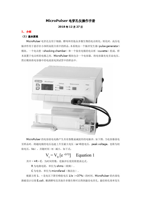
MicroPulser电穿孔仪操作手册2018年12月27日1、介绍(1)基本原理MicroPulser电穿孔仪用于细菌、酵母和其他众多微生物的电击转化,转化时,高压电脉冲作用于悬浮在小体积高阻介质中的样品。
本系统由一个脉冲发生器(pulse generator)模块、一个电击腔(shocking chamber)和一个装有电极的电击杯(cuvette)组成。
样本放置于电击杯的电极之间。
MicroPulser模块包含一个电容器,将电容器充电至高电压,然后模块将电容器中的电流放电到试管中的样品中。
MicroPulser的电容放电电路产生具有指数衰减波形的电脉冲,如下图。
当电容器放电至样品时,跨越电极的电压迅速上升至最大电压(or峰值电压,peak voltage;也称为初始电压,Vo),并随时间(t)减小,如下式:其中τ=R·C,为时间常数,是脉冲长度的简便表达式。
R为电路电阻,单位为ohms(欧姆)。
C为电容,单位为microfarad(微法拉)。
根据方程1,τ是电压下降至峰值电压1/e(~37%)的时间。
MicroPulser的内部电路被设计以使E.coli、酿酒酵母及其他许多微生物可以得到最佳电穿孔,最佳转化效率发生在大约5ms的时间常数内。
这些电穿孔条件是通过使用10微法拉电容器和将600欧姆电阻与样品池并联以及将30欧姆电阻与样品池串联来实现的。
除时间常数外,电场强度是另一个决定转化效率的重要参数。
电场强度E,是施加于电极间的电压,公式为:其中,V为施加的电压,d为电极间的距离,单位为cm。
电场强度和细胞的尺寸(size)决定了横贯每个细胞的电压降,正是电压降可能是电穿孔中电压效应的重要表现。
30欧姆串联电阻的目的是在发生电弧的情况下保护设备电路。
在正常操作条件下,当样本在高电阻介质中,电阻不会影响施加在样本上的电压。
但是,当样本的电阻较低时,电阻将极大地降低施加在样品上的电压。
日本导电仪表设定说明

日本导电仪表设定说明 Document number【980KGB-6898YT-769T8CB-246UT-18GG08】日本导电仪表FP93使用说明书一、仪表介绍05型仪表是高性能的级可编程PID调节器,它功能完善、性能优良、设计细腻,具有自由输入,四位超大高亮的字符显示,众多的状态显示。
可带4组曲线最大40段可编程、六组PID参数,带手动、停电和故障保护,三路继电器输出。
一、显示面板和功能键说明①测量值PV 显示参数类型显示出错显示②程序上升指示③程序控温指示④程序下降指示⑤调节输出指示OUT⑥运行指示 RUN⑦程序保持指示 HLD⑧确保平台指示 GUA⑨通讯连接指示 COM⑩自整定指示 AT11手动功率输出指示MAN12—14继电器输出指示EV1-EV315—18门输出指示DO1-DO4)19曲线组号(PIN)可在1至4、F中切换20曲线步号(STEP)21设定值SV显示,调节输出大小,参数值显示22循环键23 增加键12~45~1819120121122~2 924减少键25 ENT 确认键 26 GRP 组键 27 PIN 曲线键 28 STEP 步键29 RUN/RST 运行复位健 二、 仪表使用前列基本设定1、基本窗口状态下,按 键3秒,进入初始参数画面群。
2、在参数画面状态下,按键,会依次显示各初始参数,采用键可以修改各性能参数值,按ENT 键,确定参数值。
3、按PUN/RST 键可返回显示上一参数a.组数选择(Ptn )可选择1 .2 .4 分别对应 1为1组即40段编程 2为2组即20段编程基本窗口按循环键按循环键按循环按循环键按循环键按循环按循环键按循环键4为4组即10段编程b时间单位(tmvn)可选择HM MSc程序掉电保护(SAVE)可选择ON OFF“ON”为保护打开,保护打开时当电源突然断开时在恢复后程序从断开处继续执行。
“OFF”为保护关闭,保护关闭时,当电源突然断开时,再恢复后程序回到第一步成为停止状态。
日本导电仪表格设定说明
日本导电仪表FP93 使用说明书一、仪表介绍05型仪表是高性能的0.3级可编程PID 调节器,它功能完善、性能优良、设计细腻,具有自由输入,四位超大高亮的字符显示,众多的状态显示。
可带4组曲线最大40段可编程、六组PID 参数,带手动、停电和故障保护,三路继电器输出。
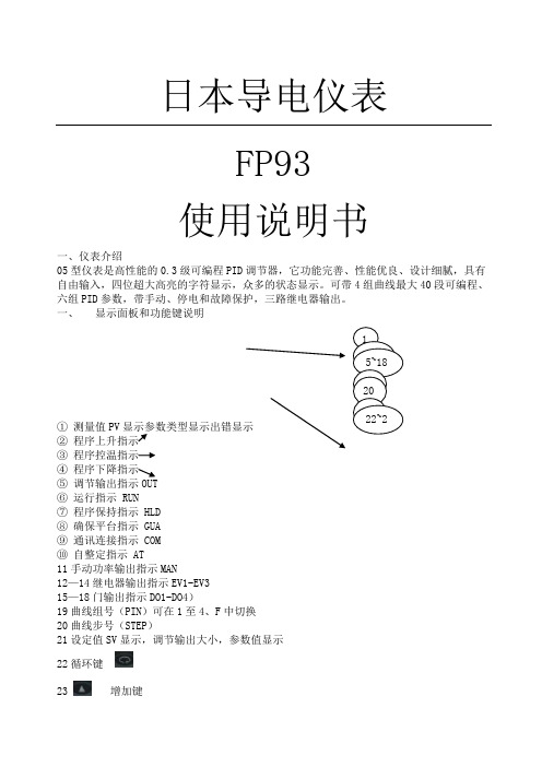
一、 显示面板和功能键说明① 测量值PV显示参数类型显示出错显示② 程序上升指示 ③ 程序控温指示 ④ 程序下降指示 ⑤ 调节输出指示OUT ⑥运行指示 RUN ⑦ 程序保持指示 HLD ⑧ 确保平台指示 GUA ⑨ 通讯连接指示 COM ⑩ 自整定指示 AT11手动功率输出指示MAN12—14继电器输出指示EV1-EV3 15—18门输出指示DO1-DO4)19曲线组号(PIN )可在1至4、F 中切换 20曲线步号(STEP )21设定值SV 显示,调节输出大小,参数值显示 22循环键23增加键24 减少键25 ENT 确认键26 GRP 组键27 PIN 曲线键28 STEP 步键29 RUN/RST运行复位健二、仪表使用前列基本设定1、基本窗口状态下,按键3秒,进入初始参数画面群。
2、在参数画面状态下,按键,会依次显示各初始参数,采用键可以修改各性能参数值,按ENT键,确定参数值。
3、按PUN/RST键可返回显示上一参数a.组数选择(Ptn)可选择1 .2 .4 分别对应1为1组即40段编程2为2组即20段编程4为4组即10段编程b时间单位(tmvn)可选择HM MSc程序掉电保护(SAVE)可选择ON OFF“ON”为保护打开,保护打开时当电源突然断开时在恢复后程序从断开处继续执行。
“OFF”为保护关闭,保护关闭时,当电源突然断开时,再恢复后程序回到第一步成为停止状态。
d 传感器量程(rang)数字表示常用代码为 01 B 偶 0—180003 S偶 0—170006 K偶 0—120007 E偶 0—70031 PT100 -200—600e 摄氏/华氏切换(Unit)可选择 C FC为摄氏 F为华氏f 误差修正(PV-b)默认值为0当PV需要修正时,用此功能正值为增加,负值为减少g 安全Lock 可选择OFF 1 2 3 默认值为OFF 当仪表不能设定时,检查此项设定,将其设定为OFF。
Impact_Twin_CN
8 不要再热源附近安装,比如说散热器,高
温暖气,火炉,或者另外的能产生的安
全规则,极化插头有 2 个叶片,一个比另
一个更宽。接地式插头有 2 个叶片外加第
三个接地端子。宽的叶片和接地端子是为
保护安全准备的。当提供的插头没法插入
插座时,可以与电工商量更换插座。
如果红色 O/L 指示灯(过载)亮起,说 明你的信号过强,你必须按下―PAD/INST‖ 以削减 20dB 的信号。
电磁兼容/电磁干扰(EMC/EMI)
引言 安全操作指南 EMC/EMI 目录 简介 快速安装向导 IMPACT TWIN 和 Ableton Live
概述 前置面板概述 后置面板概述 MIXER 页面 信道部分 1+2 线路 3-4 单元 S/PDIF 单元 ADAT TOS 单元 锁定介绍 混响单元 主控单元 插线单元
10 分钟内启动和运行 这个快速向导可以帮助你在典型应用
上设置 IMPACT TWIN。更进一步的资料和 另外的使用方案,请参照手册下面的章节。
拆包 除去包装绳,从顶部打开盒子。 从塑料袋中拿出 Impact Twin。 检查 Impact Twin 是否运输损坏。 如果发生运输损坏事件,通知运货商和供
货商。 损坏时保留所有的包装,这个将是过分暴
力运输的证据。 这也是好方法,尽可能的保留包装以备 i
昂来的运输。
检查包装目录 包装内包含物品如下: Impact Twin 音频接口 电源适配器 火线 软件 CD 安全说明 火线 800 适配器 快速启动向导
系统要求
IMPACT TWIN & ABLETON LIVE 8 LITE FOR TC ELECTRONIC
真利电力提升器操作指南(真利)说明书

#06421 TREUIL 1500 lb120V ACAVERTISSEMENTAfin d’éviter des blessures ou dommages matériels, veuillez lire et suivre TOUTES ces instructions avant d’assembler et d’utiliser le produit.CONSERVER CE MANUEL À TITRE DE RÉFÉRENCECoordonnéesMarine City, Michigan 48039Thamesville (Ontario) N0P 2K0VEUILLEZ LIRE ATTENTIVEMENT AVANT D’UTILISER VOTRE TREUIL. LE NON-RESPECT DE CES INSTRUCTIONS RISQUE DE CAUSER DE GRAVES BLESSURES OU LA MORT.POUR TOUTE QUESTION AU SUJET DE VOTRE TREUIL OU DE SON UTILISATION SÉCURITAIRE, VEUILLEZ COMMUNIQUER AVEC 1-888-546-46681. NE PAS dépasser la capacité nominale.2. NE PAS employer pour soulever ou déplacer des personnes ou des animaux.3. Une fois le câble tendu, se tenir à l’écart de celui-ci, à distance sécuritaire.4. NE JAMAIS monter sur ou se tenir près d’un câble tendu ou sous charge.5. Le câble risque de se rompre avant que le moteur ne s’arrête. Lorsque la valeur de la charge se rap-proche ou est à la capacité nominale, utiliser une poulie pour réduire la tension exercée sur le câble d’acier.6. NE PAS déplacer le véhicule lorsque le câble du treuil est en traction (NE PAS remorquer). Cela risque de provoquer la rupture du câble.7. Utiliser les points d’ancrage décrits par le fabricant.8. Le treuil n’est pas conçu pour arrimer un véhicule en place sur une longue période.9. Ne pas utiliser le treuil pour fixer un chargement pour le transport.10. Après utilisation, débrancher la télécommande et les câbles de batterie.11. Ne déplacez pas votre véhicule pendant que vous tractez un véhicule avec le treuil: une perte de trac-tion pourrait causer un contrecoup pouvant endommager le câble.12. Toujours tenir les batteries éloignées des étincelles ou des flammes. Ne jamais se pencher au-dessus du treuil pendant qu’il fonctionne. Porter des lunettes de protection.13. Ne pas employer comme engin de levage ou pour soulever des charges.14. Si le moteur cale, couper aussitôt la source d’alimentation du treuil. LES TREUILS ÉLECTRIQUES SONT CONÇUS POUR UNE UTILISATION INTERMITTENTE.15. Ne pas actionner le treuil de façon continue, sur une longue période. Si le moteur surchauffe, mettre immédiatement le treuil à l’arrêt. SI VOUS TIREZ UNE CHARGE SE RAPPROCHANT DE LA CAPACITÉ NOMINALE , ne pas actionner le treuil plus de 1 MIN. à la fois.16. NE jamais relâcher l’embrayage lorsque le câble est sous charge.17. Lorsque vous manipulez le crochet pour enrouler/dérouler le câble, utiliser une sangle à crochet.18. Toujours porter des gants pour manipuler le câble. Ne jamais laisser glisser le câble entre vos mains.19. NE PAS enrouler le câble autour d’un objet et ensuite l’accrocher sur lui-même.20. Si le véhicule est stationné en pente, placer des cales sous les roues.1564231. Winch / Treuil 2. Fairlead / Guide-câble 3. Remote Control / Télécommande4. Hook / Crochet5. Assist strap / Sangle d’appoint6. Mounting plate / Plaque de montageComposantesAVERTISSEMENT: NE PAS UTILISER SI DES COMPOSANTES SONT MANQUANTES OU ENDOMMAGÉES. CELA RISQUERAIT DECAUSER DES BLESSURES OU UN MAUVAIS FONCTIONNEMENT.Ce treuil est muni d’une plaque de montage dotée de motifs de boulons standards, ce qui permet de le fixer une grande varié-té d’attelages standards.1. Insérer les boulons dans les trous sur la plaque de mon-tage et fixer le guide-câble à la plaque de montage avec un écrou, une rondelle plate et une rondelle de blocage.2. Fixer le treuil sur la surface plane de la plaque de mon-tage. Fixer le treuil sur la plaque de montage avec un écrou, une rondelle plate et une rondelle de blocage.3. Tourner le bouton de l’embrayage à la position « OUT » pour dégager l’embrayage. Dévider un peu de câble manuellement. Faire passer le câble d’acier par la fente du guide-câble.4. Accrocher le crochet à chape au câble. Accrocher la sangle d’appoint au crochet à chape.1. La télécommande s’installe généralement sur la partie de gauche du guidon.2. Enrouler du ruban électrique autour du guidon pour empêcher la télécommande de tourner. NE PAS enrouler de ruban sur une conduite ou un câble.3. Acheminer les fils électriques entre la batterie et le treuil.4. S’assurer que le guidon est libre de tourner d’une butée à l’autre, puis connecter les fils électriques de la télécom-mande.Assemblage du treuil Montage de la télécommande (suite)NE PAS faire passer les fils électriques sur des arêtes coupantes, dans ou à proximité de pièces mobiles ou qui dégagent de la chaleur.Si le treuil s’arrête soudainement, laissez-le refroi-dir complètement. Appuyez sur le BOUTON RÉINI-TIALISER pour poursuivre.Bouton Réinitialiser1. Monter le treuil.2. Brancher le cordon d’alimentation à une prise 120 V à 3 broches correctement mise à la terre.3. Débrayer en tirant sur le bouton d’embrayage jusqu’à la position « OUT ».4. Saisir le crochet et dévider du câble jusqu’à la longueur désirée. Attacher le crochet à un point d’ancrage sécuri-taire sur l’objet tiré. Utilisation du treuilConseils pour une utilisation sécuritaireToute surcharge risque d’endommager le treuil, le moteur ou le câble d’acier. Charges de plus de 50% de la charge nominale: nous recommandons d’utiliser une poulie pour doubler la capacité du câble. C’est utile pour deux raisons:a) répartition uniforme du câble sur le tambour;(b) réduction de la tension dans le câble d’au moins 50%.Si vous doublez le câble, attachez-le au crochet de remorquage, au châssis ou à toute autre partie por-teuse. Laisser le moteur du véhicule en marche pendant l’utilisation du treuil afin d’éviter la décharge de la batterie, et pour maximiser la puissance et la vitesse du treuil. Utiliser le treuil sur une longue période sans l’assistance du moteur du véhicule risque de vider la batterie au point de rendre un démarrage impossible.Nous vous conseillons de faire des essais pour vous familiariser avec les techniques de montage, les sons que fait votre treuil en fonction de la charge, la façon dont le câble s’enroule sur le tambour, etc.Inspecter le câble d’acier et l’équipement avant chaque utilisation. Tout câble effiloché ou endommagé DOIT être immédiatement remplacé. Avant chaque utilisation, inspecter l’installation du treuil pour s’assu-rer que tous les boulons sont bien serrés. Ranger la télécommande dans un endroit où elle ne risque pas d’être endommagée.Un treuil qui montre des signes de dommages ou qui ne fonctionne pas normalement DOIT ÊTRE DÉSINS-TALLÉ IMMÉDIATEMENT ET RÉPARÉ.AutodépannageTrouver un point d’ancrage approprié, comme un tronc d’arbre ou un gros rocher.Toujours se servir d’une élingue comme point d’ancrage. (fig. 1)Le guide-câble aide à réduire la tension sur le câble pour mieux tracter latéralement sur courte distance. NE PAS TIRER une charge alors que le câble forme un angle trop aigu avec le véhicule. Si le câble d’acier s’accumule d’un côté du tambour, cela risque de causer des dommages. (fig. 2)Il est possible d"employer le treuil avec un angle de câble aigu pour redresser un véhicule, mais seulement sur une très courte distance. Pour le faire sur une plus longue distance, le câble doit former un angle de 90° par rap-port au treuil.Placer une couverture/bâche sur le câble d’acier à environ 6 pi du crochet afin d’amortir le choc en cas de rupture du câble. Pour une meilleure protection, laisser le capot du véhicule ouvert. (fig. 3)fig. 2 Angle de câble sécuritaire fig. 3 Bâche pour amortir le choc en cas de rupture du câblefig. 1 Élingue comme point d’ancrageGarantieValidité de la garantieGarantie valide à partir du jour de l’achat. Veuillez conserver la facture avec la date comme pièce justificative.Garantie de réparation/remplacementErickson Manufacturing Ltée garantit à l’acheteur initial que les composantes mécaniques sont exemptes de défauts de matériaux et de fabrication pendant 90 jours à compter de la date d’achat.Les frais de transport du produit envoyé pour réparation ou remplacement au titre de la garantie sont à la seule charge de l’acheteur. Cette garantie ne s’applique qu’à l’acheteur initial et n’est pas transférable.Ne pas retourner le produit au détaillantCommuniquer avec le service technique d’Erickson Manufacturing ltée et le service à la clientèle vous assistera par téléphone ou courriel. Les réparations ou remplacements faits sans autorisation préalable ou dans des installations non autorisées ne sont pas protégés par cette garantie.ExclusionsCette garantie ne couvre pas les réparations ni l’équipement suivants:Usure normaleCette garantie ne couvre pas la réparation lorsque l’utilisation épuise la durée de vie de l’équipement ou d’une de ses pièces.Installation, utilisation et entretienCette garantie ne couvre pas les pièces ni la main-d’œuvre si le produit a été mal utilisé, négligé, impli-qué dans un accident, s’il a fait l’objet d’un usage abusif, s’il a supporté un poids supérieur aux limites spécifiées, s’il a été modifié ou mal installé. L’entretien normal n’est pas couvert par la garantie.Autres exclusionsCette garantie exclut ce qui suit:• Défauts de fabrication apparents tels que la peinture, les décalques, etc.• Pièces d’usure• Pièces d’accessoires• Les défaillances dues à des cas de force majeure et autres événements qui échappent au contrôle du fabricant.• Les problèmes causés par des pièces qui ne sont pas des pièces d’Erickson Manufacturing ltée.Limites de la garantie implicite et dommages consécutifsErickson Manufacturing Ltée décline toute obligation de compenser les pertes de temps, d’usage du produit ou de cargaison, ainsi que toute autre réclamation fortuite ou consécutive à l’utilisation du pro-duit. CETTE GARANTIEREMPLACE TOUTES LES AUTRES GARANTIES EXPRESSES OU IMPLICITES, Y COMPRIS LES GARANTIES DE QUALITÉ MARCHANDE OU D’ADAPTATION À UN USAGE PARTICULIER.T out produit fourni en remplacement est couvert par la garantie du produit original. La durée de la garantie qui couvre le produit échangé est calculée en fonction de la date d’achat du produit original. Cette garantie donne des droits susceptibles d’être différents d’un territoire à l’autre. Les lois de votre terri-toire peuvent aussi vous accorder des droits qui ne sont pas énumérés dans la présente garantie. CoordonnéesMarine City, Michigan 48039Thamesville (Ontario) N0P 2K0Sans frais: 1-888-546-4668。
电厂听针的使用方法和注意事项
电厂听针的使用方法和注意事项电厂听针是一个用于电厂维护和操作的重要工具,它具有检测电力设备和系统状态的功能。
在本文中,我们将详细介绍电厂听针的使用方法和注意事项。
1. 什么是电厂听针?电厂听针,也称为示波针,是一种测量仪器,用于监测电流和电压信号以及检测电路中的故障。
它通常由一个细长的金属针头和一个连接到仪器的电缆组成。
2. 电厂听针的使用方法(1) 准备工作在使用电厂听针之前,确保器材完整和正常。
检查电厂听针的针头是否完好无损,电缆是否连接良好,以及仪器的电源是否正常。
根据具体的使用要求,选择合适的功率供应。
(2) 连接电缆将电缆连接到电源和待测试的电路上。
确保连接的稳固,并且不会造成电缆在使用过程中松动或断开。
注意避免电厂听针接触到电流较大的部分,以避免可能的危险。
(3) 测量信号将电厂听针的针头插入待测试的电路中,确保它与所需测量的信号点接触良好。
在测量过程中,细心观察电厂听针的指针或数字显示屏,以获取准确的测量结果。
(4) 分析数据根据测量得到的数据,结合电厂听针的使用手册或相关知识,分析并解释这些数据的意义。
根据需要,采取相应的措施来修复电路中的故障或改进电力系统的性能。
3. 注意事项(1) 安全注意在操作过程中,要注意电流和电压的安全范围,以避免触电或电流过大造成的伤害。
确认使用的电厂听针符合相应的安全标准并具备相关认证。
(2) 保养和维护定期检查电厂听针的针头和电缆是否有损坏或磨损。
及时更换任何有问题或不可靠的部件,并确保仪器清洁干燥,以延长其寿命并保持准确的测量结果。
(3) 熟悉使用手册在使用电厂听针之前,确保熟悉并理解其使用手册中的说明和要求。
这样可以更好地使用电厂听针,并避免由于错误使用而引起的问题。
4. 我对电厂听针的观点和理解电厂听针作为一种测量工具,对于电厂维护和操作非常重要。
它能够提供数据和信息,帮助工程师们更好地了解电力设备和系统的工作状态。
通过使用电厂听针,可以及时发现和解决存在的问题,并提升电力系统的可靠性和效率。
力量探索者TM 3-in-1 电能表 TDR 电缆故障找到器用于活动和未活动电缆的用户手册说明书

UsER MANUALRevison 08/19/13Power ProwlerTM3-In-1 DMM/TDR Cable Fault Finder for Energized and Unenergized CablesLW-PLR600LW-PLR600AVUser ManualTable of Contents3-In-1 DMM/TDR Cable Fault Finder for Energized and Unenergized CablesAbout the Power Prowler............................................................................3Features and Functions...........................................................................3Physical Features.....................................................................................3Optional Accessories...............................................................................4Safety Information...................................................................................5Power Prowler Description......................................................................6Terms and Descriptions...........................................................................7Types of Faults..........................................................................................7General Operations..................................................................................8On/Off.....................................................................................8Automatic Power Down...........................................................................8System Settings..........................................................................................9Digital Multimeter Options (DMM)...........................................................11Fault Location (TDR Operation)................................................................14To Begin Test for Fault Location.............................................................14Fault Location Display............................................................................15Functions........................................................................................15Changing VOP Values............................................................................16Calibrating VOP Values..........................................................................16Favorites......................................................................................18Conducting a Test...................................................................................19Live Event Detection.................................................................................20Run a Live Event Detection Test..............................................................20Maintenance.............................................................................................21Batteries...........................................................................................21Cleaning..............................................................................................21Storage........................................................................................21Customer Service......................................................................................22Specifications......................................................................................23Patents/Intellectual Property....................................................................25Warranty Information...............................................................................26Registration........................................................................................26Disposal........................................................................................26Returns. (26)Power ProwlerTMPhysical FeaturesABOUT THE POWER PROWLERThe Power Prowler is used to accurately measure voltage and resistance as well as to test voice, data, and video cables. The Power Prowlerdetermines cable length, identifies cable faults, and quickly discovers the Velocity of Propagation (VOP) for a cable using patented Spread Spectrum Time Domain Reflectometry (SSTDR).FeatureFunctionWorks on both energized and unenergized cables Discover cable events, including those which can only be shown under loadDigital Multimeter Prowler measures DC voltage, AC voltage, continuity, and resistance Fault LocationQuick picture of existing cable faults and condition Displays length reading in feet or metersInternational applications Live Event DetectionMonitors the cable for events (faults)FeatureFunctionLarge color LCD display Easy to see in all lighting environments Compact form factorUsable in tight spacesBench top, handheld, or hung up Easy to use for field flight line and production work Banana style interface Connects to many types of systemsUses 6 AA batteries (included)Provides power for 20 to 30 hoursMultilingualEnglish, French, or SpanishPower ProwlerYour Power Prowler comes in two different kits and has optional accessories available.Optional AccessoriesPart Number DescriptionLW-CA009Cable Assembly, Power Cord to 3 Banana Plugs 300VLW-AD006Multi-pin Adapter 1000V CAT III LW-CA002BNC (M) to Alligator ClipsPart NumberDescriptionLW-PLR600▪ Power Prowler Main Unit▪ DMM Meter Leads 600V CAT III ▪ Leader Cable: 5 feet 600V CAT II ▪ Flanged Crocodile Clips: red and black 600V CAT III▪BNC (F) to Double Banana Plug ▪BNC (M) to F Connection (F) ▪Hanging PouchLW-PLR600AV▪ Power Prowler main unit▪ DMM Meter Leads 600V CAT III ▪ Leader Cable: 5 feet 600V CAT II▪ Flanged Crocodile Clips:red and black 600V CAT III▪Multi-pin Adapters▪BNC (F) Double Banana Plug ▪BNC (M) to F connection (F) ▪Hanging pouchsafety InformationTo ensure safe operations of the Power Prowler, follow instructions carefully and observe warning and caution messages in this manual. Failure to observe warnings can result in severe injury or death and can damage the equipment.Notifi cation Defi nitionWarning: Potential for personal injury.Caution: Potential for damage to or destruction of equipment.Voltage!Voltage detection: Voltage on cable is unsafe or exceeds safety maximums.Conformité Européenne. Conforms to European EconomicArea directives.Disposal information▪Do not use the Power Prowler or Power Prowler accessories if they appear damaged or the unit is not working properly.▪Do not use with voltages higher than the Power Prowler’s rated voltage (600V).▪Use with caution with voltages greater than 30V AC RMS, 42V AC peak, or 60V DC.▪Disconnect circuit power and discharge high-voltage capacitors when testing capacitance, continuity, diodes, or resistance. ▪Do not use around explosive or fl ammable gas.▪Use only test leads approved by a safety agency that have the same voltage, amperage, and category as the Power Prowler. ▪Before opening the battery door, remove leader cables.▪Always wear personal protective equipment when working with the Power Prowler.▪Use caution when handling the probes and cable connections on the Power Prowler when the Voltage! icon is present.Power Prowler DescriptionWarning LEDs Banana jack connectorsTest Left/right arrowsThe four soft keys below the screen operate each of the four functions on the screen (just above each key). The following graphics appear only inhome screen mode:Multimeter 3. Live Event Detection Fault Location Live Event Detection meter Back(to previous screen)t Location Power On/OffOn the LCD screen, three main functions are displayed 2. Fault DetectionTerms Description and UsesVelocity ofPropagation (VOP)Speed of electric signal traveling through a cable; measured as a percentage of speed of light Safety Extra Low Voltage (SELV)International Electrotechnical Commission rating; defines safe voltage standards of electronic devices (60 volts DC or Peak AC; 45 volts RMS)Spread Spectrum Time Domain Reflectometry (SSTDR)Spread Spectrum Time Domain Reflectometry (SSTDR) is a measurement technique to identify faults, usually in electrical wires, by observing reflected spread spectrum signals.Terms Description and UsesOpenWire connection is not continuous throughout cable lengthShortTwo or more wires in a cable are connected (short circuit)Terms and DescriptionsTable 1 defines the terms used throughout the document and provides information to assist with proper operation and understanding of the unit and its functions.Types of FaultsTable 2 defines two possible error conditions on a cable; Short and Open. All detected cable faults will appear on the test results screen of the Power Prowler.Table 1. Terms and DescriptionsTable 2. Types of FaultsGENERAL OPERATIONsFollow instructions carefully and pay attention to warning and caution symbols. Failure to observe warnings can result in damage to the Power Prowler or cause severe injury or death.On/Off▪Turn unit on/off—press the red Power button . Automatic Power Down▪The Power Prowler automatically dims the backlight and powers off to conserve battery power if no input or activity is performed on the device. Press the setup soft key to adjust the length of time before the LCD screen dims and power off timeout.A setting is selected by pressing the up and down arrow keys. The currently selected setting is indicated by the left and right arrow icons appearing beside the function and the value of the function being highlighted with a green background. Use the left and right arrows to change the settings. To save any settings changed, press the save soft key or to exit without saving, press the Cancel soft key .sysTEM sETTINGs▪Automatic Power Off – Automatic power off is adjustablebetween 5 and 30 minutes in 1 minute increments. ▪Backlight Dimming – The dimming of the backlight to save power can be set between 1 and 9 minutes in 1 minute increments. Pressing a key restores the backlight to full brightness.▪Audio/Visual Alerts – The alert signal is used by the DMM continuity mode to indicate a low resistance. Various combinations of the buzzer and LED are available – low frequency buzzer (B1), high frequency buzzer (B2), B1 plus the alert LED (B1+LED), B2 plus the alert LED (B2+LED) or LED only (LED). An example of the alert is activated when selecting a different alert setting. ▪Feet/Meters and Leader Cable - The length units and leadercable settings are selected by this function to either: ▪Feet with no leader cable ▪Feet with a 5 foot leader cable ▪Meter with no leader cable ▪Meters with a 5 foot leader cable .mm▪Power Line Frequency (DMM) - Use the Left/Right buttons to toggle between 50 and 60Hz power line frequencies. Set to the local line frequency to reduce noise sensitivity to power lines.▪Language – English is the default language selected. Use the left and right arrow keys to select either French, Spanish, or English.▪Saving changes - Once the settings have been adjusted to the user’s satisfaction, press the save button to save the settings.▪To cancel your settings: Either press Cancel at any time and return to the previous screen , or by pressing the Back button . ▪Back button always returns to the previous screen whether it is the home screen or one of the test modes.DIGITAL MULTIMETER OPERATIONs (DMM)The Digital Multimeter Mode of the Power Prowler measures DC voltage, AC voltage, continuity, and resistance. For voltage and resistance, the Power Prowler will provide a measurement as well as minimum and maximum values.Using the Multimeter▪Press the red Power button to turn the unit on.▪Connect the appropriate adapter(s) for your application to the Power Prowler, and then connect to the cable under test.▪Select the Multimeter icon by pressing the Left/Right buttons, then press the Enter button or press the DMM soft key .▪Using the Left/Right buttons, cycle through the DMM functions toread each measurement [Direct Current (DC) Voltage, AlternatingCurrent (AC), Low Impedance Alternating Current (LoZ AC), Continuity, and Resistance (Ohms)].▪DC mode measures direct current input voltage.▪AC mode measures the RMS (root mean square) value ofalternating current voltage.▪LoZ AC or Low Impedance AC Mode sets input impedanceto about 1,000 Ohms and measures the RMS value of alternatingcurrent voltages. This reduces the chances of false readings dueto probes picking up AC voltage before they are connected to thetest circuit.▪Continuity Mode identifies continuity by measuring the resis-tance between input probes and displays either OL (overload) foran open circuit or Low Resistance (LO). Maximum resistance todetect continuity is 250 Ohms.▪Resistance Mode measures and displays resistance betweeninput probes.The display shows real-time input unless you press Hold or Min/Max. When input exceeds your presently selected range, the letters OL (overload) appear. When your input is out of range or over 60V (AC or DC), the high voltage warning sign appears, alerting you to a potentially hazardous voltage.All DMM modes display a bar graph that approximates the percent of the full range of the function selected.Common Voltage Mode FunctionsThe following common voltage mode functions are used when DC Voltage, AC Voltage, or Low Impedance have been selected (see above).▪Hold (freezes display at current measurement)▪Press the Hold soft key to freeze the display. The word Holdappears in red on the screen.▪Press the Hold soft key to resume real time measurement.▪Range (manually select a Range or use the automatic range AutoRange). The range is displayed to the lower right of the measurement.▪Press the Range soft key repeatedly to cycle through ManualRange options or Auto Range.▪Auto Range is the default. Ranges available are: 0-4V, 0-40V,0-400V, and 0-600V.▪Min/Max (displays maximum and minimum values, as well asaverage value)▪Once range and the desired voltage measurements have beenselected, press the Min/Max soft key to display minimum/maximums. If a new high or low measurement is encountered, theMin/Max display changes.▪To display an average measurement, press the Average soft key(which changes to Min/Max). An average value will be displayedand change according to continuing real-time input.▪Press the Hold soft key to freeze the display. The word HOLD willappear on the screen in red.▪Press the Hold soft key to resume real-time displays.▪Press the Restart soft key to reset the AVG and VDC or VACreadings and display new inputs.▪Press the Min/Max soft key to switch back to the Min/Maxmode.▪Pressing the Restart soft key will restart the accumulation of Max/Min readings in the Min/Max mode.▪Press the Back button to exit Min/Max and return to the normal voltage display screen.▪Press the Back button to exit the current DMM function and return to the home screen.The Power Prowler determines the length of a variety of cable types and calculates the VOP of a cable with known length.When connecting to a cable, use proper adapters for the application. When connecting to energized cables over 60V, you will need the leader cable (CA008) rated at 600V CAT III. If a leader cable is being used, the leader installed option should be selected for a more accurate length reading. See Setting Options for more information on leader settings (page 9).Internal Power Prowler components are protected to 600V peak AC or DC. Connecting the unit to cabling with voltages above 600V peak AC or DC may damage the unit and pose a safety hazard for the user.To Begin a Fault Location Test▪Press the red Power button to turn the unit on. ▪Connect the proper adapter for your application to the Power Prowler, and then connect to the cable under test. Select the Fault Location icon by pressing the Left/Right buttons, then press the Enter button or press the Fault Location soft key . ▪Use the Left/Right buttons to scroll to the cable type being tested. The cable type appears on the bottom of the screen. ▪Press the Test button to measure the length of the cable or theFAULT LOCATION (ssTDR OPERATION)Fault Location Display▪Press the red Power button to turn the unit on. ▪Connect the proper adapter for your application to the Power Prowler, and then connect to the cable under test. Select the Fault Location icon by pressing the Left/Right buttons, then press the Enter button or press the Fault Location soft key . ▪Use the Left/Right buttons to scroll to the cable type being tested. The cable type appears on the bottom of the screen. ▪Press the Test button to measure the length of the cable or thedistance to a fault.Test leads being usedBattery Life Cable Type & VOPSettingsCalibration Favorites bookmarkCable Fault (open or short)Valid length indicatorFunctionsThe following functions are used by pressing tthe appropriate soft key or button.▪Favorites - activates favorites screen to select or bookmark cable types and VOPs.▪Calibration - activates calibration to calculate VOP for existing cable.▪system options - access system options such as length units (feet or meters).▪Left/Right Arrow Buttons - press to select cable type. ▪Up/Down Arrow Buttons - press to adjust VOP value. ▪Back - exit length mode and return to main screen.Mode Indicator▪The left/right cursor buttons scroll through preset cable types andVOP values (as well as values you may have saved). This list includes generic names (Custom Cable 1, for example) used to save customVOP values.▪When performing a test, the valid length indicator (=) appears on the top left portion of the screen. This shows that the displayed lengthis based on a current cable type and VOP. The indicator is removed if the cable type and/or VOP have changed until another test has been performed.Changing VOP ValuesIn the fault location mode, you can adjust the velocity of propagation (VOP) value for any cable and save your adjustment.▪Check to see if your Power Prowler is in the correct Leader/No Leader setting (see system settings page 9).▪Press the Up/Down buttons to change the VOP. The digits that arechanged will be displayed in grey. Hold the button down to repeat/scroll.▪A red Edit label appears on the screen when the fi rst up/down button is pressed.▪Press the Test button to measure the cable with the new VOPvalue.▪Press the Default soft key to return to the default VOP for the current cable type.▪Press the Return soft key to exit editing with the current VOP value. This does not update the cable type with the new VOP value.▪Press the save soft key to save your new VOP value for your current cable type and exit editing.▪Press the Cancel soft key to restore the VOP value you hadbefore editing and return to the main Fault Location display screen. Calibrating VOP ValuesTo fi nd the VOP value with a known length of cable:▪Press the CAL soft key.▪A red Calibrate label appears on the screen.▪Use the Up/Down buttons to match the known cable length (hold the cursor key down to rapidly change the length).▪Use the +50 or -50 soft keys to increase or decrease the length by 50 feet (approximately 20 meters).▪When calibrating a known cable under 50ft (15m) accuracy will be low.▪Press the Test button to calculate VOP from your known cable length. ▪Press the save soft key to save the results, or to return to the test screen without saving changes .To select a Favorite cable type:▪Press the Up/Down buttons to scroll and highlight a cable type in the list.▪Press the Enter button to select the highlighted cable type as the current cable type and return to the Fault Location screen.To edit the favorites list:▪Press the Favorites soft key . ▪Select one of the 6 locations on the table using the Up/Down buttons to highlight a desired row in the table. ▪Use Left/Right buttons to locate a cable type to store in the highlighted row of favorites or press the + soft key to add the current cable type to the selected favorites slot. Press the Trash Can soft key to clear the highlighted row. ▪The table contents are bookmarks to cable types (if you change the VOP for a cable type, the table is updated automatically). ▪Press the save soft key to save your changes. ▪Press the Cancel soft key to discard changes and exit.FavoritesThe favorites screen is accessible by pressing the Favorites soft key .A table will appear with six user-selected cable types.Conducting a TestOnce your VOP and cable type have been selected, you can run a test. ▪Press the green Test button to run a Fault Location test.▪The graphic on the left side of the screen will display an open or short condition.ShortOpenLive Event Detection monitors a cable for changes. In this mode, the Power Prowler detects, locates, and time stamps the fault. How to run a Live Event Detection Test▪Press the red Power button to turn the unit on. ▪Connect the proper adapter for your application to the Power Prowler, and then connect to the cable under test. Use the right arrow button to scroll to the Live Event Detection icon then press the Enter button or you can press the Live Event Detection soft key . ▪Use the Left/Right buttons to select the cable type or edit the VOP (as described in Fault Location, on page 15). When editing the VOP you cannot use the Test button to verify the new VOP value. ▪Press the Test button to begin testing.On the lower left side of the screen, a timer will appear displaying elapsed time for the test. The Power Prowler will identify any changes (event) to the cable condition (open or short condition). The test will stop when a change is detected or if the cancel soft key is pressed.LIVE EVENT DETECTIONMAINTENANCEBatteries▪The Power Prowler is powered by 6 alkaline AA batteries.▪When the battery life indicator is flashing, or the onscreen battery life indicator shows only one bar, it’s time to replace the batteries.▪Make sure the Power Prowler is turned OFF.▪Using a Philips head screwdriver, remove the back panel.▪Take the old batteries out and replace with 6 fresh AA batteries.▪DISPOSAL: Batteries are considered hazardous waste. Dispose ofthem at a hazardous waste facility.Cleaning▪Use a clean, damp cloth to clean the Power Prowler.▪Before cleaning, disconnect all cables from the Power Prowler. Failing to disconnect cables can damage the device and causepersonal injury.▪Do not use harsh cleaners, abrasives, or solvents.storage▪When not in use, store the Power Prowler in a dry, protective case.Batteries should be removed if the device is stored for a long time.▪Do not expose the Power Prowler to high temperatures (above 80°C) or humidity. See the specifications section for temperature limits.CUsTOMER sERVICEFor technical information, visit . For customer service,***********************************.Contact Numbers: Phone: 855-346-3358Fax: 801-293-8301Address: 10288 South Jordan Gateway, Suite ASouth Jordan, Utah 84095USATechnologyU.S. Patents and Patents Pending Multimeter sectionDescription RangeResolu-tion Accuracy (% + counts)DC Volts 600V 400.0V 40.00V 4.000V1V 0.1V 0.01V 0.001V ±(0.5% + 2)Auto-ACV LoZ True-rms 600V0.1V ±(2.0% + 3) DC, 45~500 Hz ±(4.0% + 3) DC, 500~1 KHz AC Volts True-rms 600V0.1V ±(1.0% + 3) DC, 45~500 Hz ±(2.0% + 3) DC, 500~1 KHz Ohms 4.0 K Ω 40.00 K Ω400.0 M Ω40.0 M Ω0.0t01 K Ω0.01 K Ω 0. 1 K Ω0.00 1 M Ω0.01 M Ω±(0.9% + 2)±(0.9% + 2)±(0.9% + 2)±(0.9% + 2)±(0.9% + 2)Off mode - 4.25 uA Multimeter mode: 81 mA with backlight, 41 mA dim backlight Fault Location: 82mA - one test per minute with backlight Live Event Detection: 115 mA when active with backlight, 75 mA dim backlightBattery Life 6 x AA alkaline batteries Standby: life of the battery Operating: 20 to 30 hours, mode dependent Batteries are includedMaximum Range 12,000 ft (3,657 m) at .999 VOP VOP (%) with 3 digit precision ranging from 20.0% to 99.9%Output Connector Banana Jacks 600V CAT IIILeader CableCable Assembly, 5 ft. (1.5 m) 600 Volt CAT II, 95 OhmAltitude6500 ft (2000m) operatingTemperature Operating: 14 to 122°F (-10 to 50°C);Storage: -4 to +140°F (-20 to 60°C)Humidity10 to 90% non-condensingEnclosure High-strength PC/ABS plastic with V0 rating with boot size 1.85”H x 3.6”W x 6.8”L (4.7 x 9.15 x 17.3 cm) Weight With batteries: 1 lb 2 oz (510 g)safety Compliances PENDING: Complies with ANSI/ISA 82.02.01 (61010-1) 2004, CAN/CSA-C22.2 No 61010-1-04, UL 6101B (2003) and IEC/EN 61010-1 2nd Edition for measurement Category II, 600 V, EMC EN61326-1Warranty 1 YearPATENTs/INTELLECTUAL PROPERTy LiveWire Power Prowler is the trademark of LiveWire Innovation, Inc. and is covered by one or more patents as described at /about/patents-trademarks/.Warranty InformationLiveWire Power Prowler is covered by the Limited Product Warranty set forth in and subject to the terms, conditions, limitations and disclaimers set forth in LiveWire's General Terms, /terms/. No further warranties either implied or express will apply, nor will responsibility for operation of this device be assumed by LiveWire Innovation.Product RegistrationRegistering your Power Prowlerallows you to access support information and receive product updates. Register your products on the LiveWire Innovation website: /warranty. DisposalWEEE Compliant: Prior to disposal of this product, pleasecontact LiveWire Innovation for proper disposal options. ReturnsYou must fi rst request a Return Materials Authorization number and receive shipping instructions by contacting the Customer Service Department at******************************************************.Note: Shipments will not be accepted without this number, which must be clearly marked on the shipping label.Power Prowler TMPower Prowler TMThe 21st Century Dual Mode TDR for Testing and Monitoring Energized and Unenergized CablesUser Manual For technical information and customer support, please visit or send ***************************************.Contact Numbers: Phone: 855-346-3358Fax: 801-293-8301 Address: 10288 South Jordan Gateway, Suite A South Jordan, Utah 84095 USA。
电员针使用手册
恒流低频灸(原名电员针)应用手册一、绪论(一)适应症经筋痛。
经筋与经脉是构成经络系统的体系。
经筋是指筋肉(肌肉、韧带及附属组织等软组织部分),经脉则指血管、经隧之属。
恒流电员针治疗对象除血管病以外的筋骨痛、骨伤病。
(二)经筋病理想的治疗方案。
软组织损伤急性期、局部疼痛、肌痉挛、慢性期瘢痕粘连、活动受限、肌肉挛缩,理想的治疗原则应包含止痛、解痉、松动关节、牵伸挛缩。
一般操作程序:准备安放电极,调频2档,调压2-3档,少用高档,以延长仪器使用年限,接通电源。
频率与波形见下表。
频率与波形档次波形频率HZ1 慢连续波 22 快连续波163 短疏密波2-154 长疏密波2-1005 低频间断波1006 中频间断波10001.2.1 砭石刮拨与理筋、经脉走形垂直刮拨,松解粘连,缓解经筋痉挛。
1.2.2 恒流灸止痛横流沿经筋、经脉流通8—10分钟后出现明显镇痛作用。
1.2.3 整骨复位治疗骨错缝采用三维运动法,清除关节周围软组织粘连、挛缩等嵌顿因素,通过磨合,促进骨错缝复位。
1.2.4 纵牵横掰横掰分筋,松筋止痛,纵向牵筋,拉伸挛缩,促进筋跳槽复位。
(三)经筋痛优选的治疗方法。
1.3.1 剥离组织粘连,砭板优于电员针。
选用11×6cm、厚0.5cm砭板横刮剥离粘连,板厚刃顿,不易划伤皮肤;板宽易用手掌使力,刮的较深;板长可以循筋纵刮,较为省时。
若刮拨同时配合运动患肢,疗效更好。
电员针头大又圆,难以插入骨缝。
1.3.2 止痛效果横流低频灸优于恒压低频针(电员针),二者优缺点见下表。
恒压电员针(1997年设计)横流低频灸(2012年设计)双向尖波,刺激性强。
单一脉冲,脉冲浅而窄,止痛效果差。
不易定量控制,不易操作。
主要用于理疗仪器。
铜头裸露,易受外界温度影响。
脉冲圆滑,刺激性弱。
5种波形可调,脉冲深而广,止痛效果好。
容易定量控制,操作方便。
主要用于科研仪器。
增加泗滨砭石套环,可自动吸收、放射红外线,保持针头温度。
电员针疗法简介

电员针疗法简介:是一种传统与现代相结合的新型中医外治法,它是古代员针的基础上融入现代脉冲电疗技术,同时配合三维运动施治,对软组织疾病有很强的针对性,尤其是粘连性肩周炎、颈椎病、腰椎盘突出症、膝关节骨性关节炎等骨质增生性疾病疗效更为明显.适应症达50余种,还可以治疗某些内、妇科疾病,如偏瘫、胃浣痛、尿失禁、附件炎等.电员针疗法是在古代员针基础上融入现代脉冲电疗技术,同时配合运动施治,以“通”(电脉冲通经活络.可止痛、消炎、解痉)、“松”(员针可松解粘连、瘢痕)、“复”(运动可促进关节微小移位复位)三种功能达到治疗多种疾病的目的。
电员针疗法系由对我国医疗卫生事业有突出贡献的专家、解放军第152医院主任医师张炳然教授,历经20年的临床实践和研究创新而发明的,具有科学性、(共1页)电员针疗法是在古代员针基础上融入现代脉冲电疗技术,同时配合运动施治,以"通"(电脉冲通经活络,可止痛,消炎,解痉),"松"(员针可松解粘连,瘢痕),"复"(运动可促进关节微小移位复位)三种功能达到治疗多种疾病的目的.该疗法获全军科技成果奖,被列为全军医学成果推广项目.电员针疗法物色该疗法简便易行,无创无痛,起效迅速,确系中医特色专科(专病)建设的理想项目,尤其适用于城乡基层医疗单位.电员针疗法适应证对软组织疾病有很强的针对性,尤其是粘连性肩周炎,颈椎病,腰椎间盘突出症,膝关节骨性关节炎等骨质增生性疾病疗效更为明显,对急性软组织损伤效果尤佳.适应证达#"余种,还可治疗某些内,妇科疾病,如偏瘫,胃脘痛,尿失禁,附件炎等.授课内容由电员针发明人张炳然教授亲自讲授:(一)颈,肩,胸,腰,髋,膝,足七个部位%""余种软组织病的快速诊断法;(二)%"余种退行性骨关节病和腰椎间盘突出症的"电员针———三维运动"疗法;(三)!"余种软组织病的"电员针———六步松"疗法.软组织病专家张炳然和他的电员针患者到医院送感谢信,都会在痊愈之后。
电源锐芯电钻说明书

Item #341095614"C U T-O F F S S A WA s s e m b l y a a n dO p e r a t i o n I I n s t r u c t i o n sF o r Y Y o u r O O w n S S a f e t y,r e a d t t h i s I I n s t r u c t i o n M M a n u a l u u s i n g t t h i s s s a wContentsGENERAL SAFETY RULES . . . . . . . . . . . . . . . . . . . . . . . . . . . . . . . . . . . . . . . . . . . . . . . . . . . . . . . . . . . . . . . . . . . . . . . . . . . . . . .2 SPECIAL SAFETY RULES FOR CUT-OFF SAWS . . . . . . . . . . . . . . . . . . . . . . . . . . . . . . . . . . . . . . . . . . . . . . . . . . . . . . . . . . . . .3 MOTOR SPECIFICATIONS AND ELECTRICAL REQUIREMENTS . . . . . . . . . . . . . . . . . . . . . . . . . . . . . . . . . . . . . . . . . . . .4 GETTING TO KNOW YOUR CUT-OFF SAW . . . . . . . . . . . . . . . . . . . . . . . . . . . . . . . . . . . . . . . . . . . . . . . . . . . . . . . . . . . . . . . . .5 ASSEMBLY& ADJUSTINGOn-off Switch . . . . . . . . . . . . . . . . . . . . . . . . . . . . . . . . . . . . . . . . . . . . . . . . . . . . . . . . . . . . . . . . . . . . . . . . . . . . . . . . . . . . . . . . .6 Using the Head Lock Down Pin . . . . . . . . . . . . . . . . . . . . . . . . . . . . . . . . . . . . . . . . . . . . . . . . . . . . . . . . . . . . . . . . . . . . . . . . . .6 Carrying the Tool . . . . . . . . . . . . . . . . . . . . . . . . . . . . . . . . . . . . . . . . . . . . . . . . . . . . . . . . . . . . . . . . . . . . . . . . . . . . . . . . . . . . . .6 Adjusting the Vise . . . . . . . . . . . . . . . . . . . . . . . . . . . . . . . . . . . . . . . . . . . . . . . . . . . . . . . . . . . . . . . . . . . . . . . . . . . . . . . . . . . . .7 Removing or Installing the Wheels . . . . . . . . . . . . . . . . . . . . . . . . . . . . . . . . . . . . . . . . . . . . . . . . . . . . . . . . . . . . . . . . . . . . . . .7 MAINTAINING YOUR CUT-OFF SAW . . . . . . . . . . . . . . . . . . . . . . . . . . . . . . . . . . . . . . . . . . . . . . . . . . . . . . . . . . . . . . . . . . . . . .8 TROUBLE SHOOTING . . . . . . . . . . . . . . . . . . . . . . . . . . . . . . . . . . . . . . . . . . . . . . . . . . . . . . . . . . . . . . . . . . . . . . . . . . . . . . . . . . .9 CONTENT PARTS . . . . . . . . . . . . . . . . . . . . . . . . . . . . . . . . . . . . . . . . . . . . . . . . . . . . . . . . . . . . . . . . . . . . . . . . . . . . . . . . . . . . . . .10General Safety Rules1.Know Your Power ToolRead the owner's manual and labels affixed to the tool. Learn it's application and limitations as well as the potential hazards pertaining to this tool.2.Ground all ToolsIf tool is equipped with three-prong plug, it should be plugged into a three-hole electrical receptacle. If an adapter is used to accommodate a two-prong receptacle, the adapter lug mast be attached to a known ground. Never remove the third prong.3.Keep Work Area CleanCluttered areas and benches invite accidents. Floor must not be slippery due to wax or saw-dust.4.Avoid Dangerous EnvironmentsDon't use power tools in damp or wet locations or expose them to rain. Keep work areas well lighted.5.Keep Children AwayAll visitors should keep a safe distance away from work area.6.Don't Force ToolIt will do the job better and safer at the rate for which it was designed.e Right ToolDon't force tools or attachments to do a job they were not designed for.8.Wear Proper ApparelDo not wear loose clothing, gloves, neckties or jewelry (rings, wrist watches) which may get caught in moving parts. N ON SLIP footwear is recommended. Wear protective hair covering to contain long hair. Roll long sleeves to above the elbow.9.Don't OverreachKeep proper footing and balance at all times.10.Maintain Tools with CareKeep tools sharp and clean for best and safest performance. Follow instructions for lubricating and changing blades, etc.11.Avoid Accidental StartingMake sure switch is in "off" position before plugging in.12.Check Damaged PartsBefore further use of the tool, a guard or other part that is damaged, should be carefully checked to ensure that it will operate properly and perform it's intended function. Check for alignment of moving parts, breakage of parts, mounting, and any other conditions that may effect it's operation. A guard or other part that is damaged should be properly repaired or replaced.13.Never Leave Tool Running UnattendedTurn power off. Don't leave tool until it comes to a complete stop.Special Safety Rules for Cut-Off Saws1.WARNING: Do not operate your abrasive cut-off saw until it is completely assembled andinstalled according to the instructions.2.WEAR safety goggles, face shield, respirator, body apron, head covering, safety shoes, long tightfitting sleeves and gloves.E ONLY recommended reinforced abrasive wheels with blotters.4.TIGHTEN arbor screw and all clamps before operating.5.MAKE SURE spindle lock is disengaged before operating.6.ALWAYS keep guards in place and working properly.7.KEEP hands clear of cut-off wheel.8.SECURE workpiece properly. Work should be straight and firmly clamped to avoid possiblemovement and pinching as the cut nears completion.9.NEVER reach behind or beneath the cut-off wheel.10.MAKE SURE the wheel has come to a complete stop before removing or securing workpiece orchanging workpiece angle.11.MAKE SURE the inside surfaces of the wheel are free from any foreign matter.12.WHEN MOUNTING tighten the arbor screw only enough to hold the wheel firmly and to preventslippage. Excessive tightening may result in damaging the wheel and springing the wheel flanges.E ONLY abrasive wheels rated at 3900 RPM or higher.14.ALWAYS check the wheel for cracks or other damage before operation. Replace cracked ordamaged wheels immediately.E ONLY wheel flanges specified for your machine.16.MAKE SURE abrasive wheel is not contacting workpiece before switch is turned on.17.AFTER TURNING THE MACHINE ON, lower wheel lightly, until it comes into contact with theworkpiece and then draw wheel firmly through the cut. DO NOT allow the wheel to chatter and jump as this may cause the wheel to wear out, resulting in poor cutting and possible broken wheels.18.THE NUMBER of cuts per wheel, as well as the quality of the cut, may vary considerably with thecutting time. Fast cuts cause the wheel to wear more rapidly but also help to reduce discoloration and burr. This is especially noticeable when cutting light gauge tubing. When coming through the bottom wall, with the longer arc of contact, do not slow up, but give a vigorous pull. This keeps the metal from overheating and dragging off in a heavy burr.E the wheel guard at all times.20.NEVER operate the machine in an area with flammable liquids or gasses.21.TO A VOID electric shock, do not use under damp conditions or expose to rain.22.THIS tool is designed for ferrous metals only. DO N OT attempt to cut wood, masonry, aluminumor magnesium with this tool.23.ALWAYS run the tool for approximately one minute before cutting. If the wheel has an undetectedcrack or flaw, it could burst in less than one minute.24.SHUT OFF power before servicing or adjusting tool.25.SHOULD any part of your machine be missing, damaged or fail in any way, or any electricalcomponent fail to perform properly, shut-off switch and remove plug from power supply outlet.Replace missing, damaged or failed parts before resuming operation.26.REPLACE cracked wheel immediately.Motor Specifications and Electrical Requirements Grounded Tools With Three-Prong PlugsWARNING:Improper grounding can shock, burn or electrocute.Grounding of this tool is necessary while in use to protect you from electric shock or electrocution. This tool is equipped with an approved three-conductor cord and three-prong ground-type plug to fit the proper grounding-type receptacle. Do not remove grounding prong from the three-prong grounding-type plug. The green (or green and yellow) conductor in the cord is the grounding wire. Never connect the green ( or green and yellow) wire to a live terminal. Your unit is for use on less than 150 volts and it has a plug that looks like Fig "A".An adapter, Fig. "B" and "C", is available for connecting Fig "A" plugs to two-prong receptacles. The green colored rigid ear, lug, etc, extending from the adapter must be connected to a permanent ground such as a properly grounded outlet box.NOTE: The grounding adapter, Fig "C", is prohibited in Canada by Canadian Electrical Code part-1. Therefore the instructions for it's use are not applicable in Canada.If your unit is for use on 150 to 250 volts, it had a plug that looks like Fig "D". No adapter is available for a plug like Fig "D".Extension CordsWARNING: Use of damaged cords can shock, burn, or electrocute.Replace damaged or worn cords immediately. The table shows the correct size to use, depending on cord length and nameplate amperage rating of tool. If in doubt, use the next heavier gauge. An undersized cord will cause a drop in line voltage, resulting in loss of power and over-heating.NOTE:The smaller the gauge number, the heavier the cord. Use only three-wire extension cords with three-hole receptacles, which accept the tool plug and have a three-prong grounding-type plugs.Getting To Know Your Cut-Off Saw1.Spindle LockFor changing wheels easily.2.Head Lock Down PinYour Cut-Off Saw can be locked in the lowered position for compact storage and portability.3.14" Abrasive WheelCuts a standard 10 pack bundle of steel drywall studs in a single pass.Guard4. WheelFor the operator's protection, the Wheel Guard should always be lowered in place and working properly during the cutting operation.5.Quick Release LeverSpeeds-up work with fast, easy clamping.6.Adjustable Pivoting FencePivots 0 to 45º Left and Right for secure clamping of material while making angle cuts.7.HandleLarge handle for easy carrying.8.Adjustable Depth StopYour Cut-Off Saw is equipped with an adjustable depth stop that allows precise, repeatable cutting depths. As the wheel wears, or when replacing a wheel, it will be necessary to adjust this stop to make complete cuts and ensure that the wheel does not cut through the surface the tool is resting on.To start the tool, depress the lock-off button and then squeezePINTHE TOOLTo obtain maximum cutting depth, position adjustable pivoting fence so material being cut isINSTALLING THE WHEELSRaise wheel guard as shown in Fig. B, push in spindlelock (Fig. A), and loosen the hex head bolt in the centreof abrasive wheel by rotating counter-clockwise withRemove the hex head bolt, spring washer, arborCarefully install the new abrasive wheel onto thespindle shaft and replace outside flange, arbor washer,Press in spindle lock and tighten hex bolt with theWhenever replacing a wheel, always adjust thedepth stop bolt to prevent the wheel from cutting into thesurface the tool is resting on. Failure to make the adjustmentMaintaining Your Cut-Off SawAfter each use: Disconnect the plug from the power source, remove the wheel and washers and wipe deposits of dust from the housing and guard. Check operation and condition of the lower guard, it should be securely attached and working properly. The cord and tool should be wiped occasionally with a clean cloth and mild soap only to prevent deterioration from oil and grease.WARNING:Certain cleaning agents and solvents can damage plastic parts. Some of these are: gasoline, carbon tetrachloride, chlorinated cleaning solvents, ammonia and household detergents that contain ammonia. Avoiding use of these and other types of cleaning agents minimizes the probability of damage. WARNING: The use of any other accessories not specified in this manual may create a hazard. Recommended Cutting Capacity:WARNING: All repairs –– electrical or mechanical –– should be attempted only by trained repairmen. Contact the nearest Authorized Service Centre for repair service. Use only identical replacement parts; any other may create a hazard.The gear case has been completely lubricated at the factory. However, after six months to one year, depending upon use, it's wise to return your cut-off saw to the nearest Authorized Service Centre for the following:• Brushes replaced• Electrical system tested• Gears relubricated with fresh lubricant• Parts cleaned and inspected• Any other repairsWARNING:Use of tool beyond recommended capacities may lead to motor burn-out and possible electric shock.Applicable Wheel355 mm (14") outer diameter x less than 4.5 mm (3/16") thicknessDimensions x 25.4 mm (1") hole diameterWorkpieceConfiguration(Cross-section)MaximumCutting 1/2"2"5"2"1/2"5"CapacityTrouble ShootingC H O P S A W P A R T S L I S T。
ZL2135遥控型电缆安全刺扎器使用手册

Z L2135遥控型电缆安全刺扎器使用手册(总15页)--本页仅作为文档封面,使用时请直接删除即可----内页可以根据需求调整合适字体及大小--ZL2135遥控型电缆安全刺扎器使用手册武汉智能星电气有限公司2012-2-20目录一、概述..................................错误!未定义书签。
二、功能特点及技术指标....................错误!未定义书签。
三、结构示意及保养........................错误!未定义书签。
四、空试扎实验............................错误!未定义书签。
五、使用方法..............................错误!未定义书签。
六、使用注意事项..........................错误!未定义书签。
七、运输、贮存............................错误!未定义书签。
八、售后服务..............................错误!未定义书签。
ZL2135遥控型电缆安全刺扎器一、概述ZL2135遥控型电缆安全刺扎器是我公司在总结国内外多家电缆安全刺扎器的基础上推出的新一代电缆安全刺扎工具,它具有双枪双角度刺扎被测电缆,功能可遥控、线控自动定时两种控制方式。
极大地提高了电缆刺扎的安全性、及可靠性。
实现了一次刺扎两个角度同时完成,是电缆施工、维护工作者的必备工具。
多年以来,电力电缆运行与维护部门对电力电缆刺扎,均按照行业标准DL409-91第234条要求,采用人工试扎待锯电缆,一旦电缆识别出错,误刺扎带电运行电缆将造成极大的危害。
ZL2135电缆安全刺扎器是ZL2134电缆识别仪的配套产品,在对多条电缆识别后针对某条电缆开锯前的安全遥控刺扎设备,它采用了非接触式控制(遥控、线控自动定时)模式,彻底解决了人工刺扎电缆的人身安全问题。
电脉美发机手册说明书
When using an electrical appliance, basic precautions must always be followed, including the followingREAD ALL INSTRUCTIONS BEFORE USING THIS MACHINEn To reduce the risk of fire, electric shock, or injury:1. Do not leave appliance when plugged in. Unplug from outlet when not in use and before servicing.2. Do not use outdoors or on wet surfaces.3. Do not use near small children. Do not allow to be used as a toy. Close attention is necessary when used by or near children.4. Use only as described in this manual. Use only manufacturer's recommended attachments.5. Do not use with damaged cord or plug. If appliance is not working as it should, has been dropped, damaged, left outdoors, or dropped into water, return it to a service center.6. Do not pull or carry by cord, use cord as a handle, close a door on cord, or pull cord around sharp edges or corners. Do not run appliance over cord. Keep cord away from heated surfaces.7. Do not unplug by pulling on cord. To unplug, grasp the plug, not the cord.8. Do not handle plug or appliance with wet hands.9. Do not put any object into openings. Do not use with any opening blocked; keep free of dust, lint, hair, and anything that may reduce air flow.10. Keep hair, loose clothing, fingers, and all parts of body away from openings and moving parts. Do not place fingers or other body parts under vacuum unless unplugged.11. Do not pick up anything that is burning or smoking, such as cigarettes, matches, or hot ashes12. Do not use without dust bag and/or filters in place.13. Turn off all controls before unplugging.14. Use extra care when cleaning on stairs.15. Do not use to pick up flammable or combustible liquids such as gasoline or use in areas where they may be present.16. Machines can cause a fire when operated near flammable vapors or materials. Do not operate this machine near flammable fluids, dust or vapors.17. Maintenance and repairs must be done by qualified personnel.18. Connect to a properly grounded outlet only. See Grounding Instructions.19. Do not use machine as a step.20. If used on plush carpet or carpet with thick padding, do not leave machine in one place with machine turned on.This appliance must be grounded. If it should malfunction or breakdown, grounding provides a path of least resistance for electric current to reduce the risk of electric shock. This appliance is equipped with a cord having an equipment-grounding conductor and grounding plug. The plug must be inserted into an appropriate outlet that is properly installed and grounded in accordance with all local codes and ordinances.Accidents due to misuse can only be prevented by those using the machine. To guard against injury, basic safety precautions should be observed, including the following:Read and follow all safety instructions.WARNING: ELECTRIC SHOCK COULD OCCUR IF USEDOUTDOORS OR ON WET SURFACESThis vacuum cleaner is designed to be safe when used to perform cleaning functions. Should damage occur to electrical or mechanical parts, cleaner should be repaired by WINDSOR or competent service station before using in order to avoid further damage to machine or physical injury to user.A damaged power cord could cause electrical shock and/or fire. To minimize this possibility observe the following precautions:Do not run cleaner over power cord.Avoid closing doors on power cord, pulling it around sharp edges, or placing sharp-edged objects upon it.Wind cord no tighter than is necessary to retain it on the cord hooks.When disconnecting power cord from electrical outlet, grasp the plug. Pulling it out by the cord itself can damage cord insulation and internal connections to plug.Your vacuum cleaner creates suction and contains a revolving brush. To avoid bodily injury from suction or moving parts, vacuum cleaner brush should not be placed against, or in close proximity of loose clothing, jewelry, hair or body surfaces while cleaner is connected to electrical outlet. Cleaner should not be used to vacuum clothing while it is being worn. Keep children away from machine when in operation or plugged in.If used on plush carpet or carpet with thick padding, turn off unit when handle is in upright position. When using accessory tools, keep floor brush off carpet by keeping handle in locked position and lowering handle with one hand to raise brush off floor. Operate accessories with other hand.Always plug your cleaner into a standard wall outlet. Use of extension cord or light socket with inadequate current-carrying capacity could result in electric shock or fire hazard.Disconnect cleaner from electrical outlet before servicing, such as changing bags or belts. You could receive bodily injury from moving parts of machine should switch accidentally be turned on. Disconnect cleaner from electrical outlet before detaching powerhead.Do not use your vacuum cleaner in areas where flammable and/or explosive vapor or dust is present to avoid possibility of fire or explosion. Some cleaning fluids can produce such vapors. Areas on which cleaning fluids have been used should be completely dry and thoroughly aired before being vacuumed.To avoid fire hazard, do not pick up matches, fireplace ashes, or smoking material with cleaner.Keep your work area well lighted to avoid picking up harmful materials (such as liquids, sharp objects, or burning substances) and avoid tripping accidents.Use care when operating the cleaner on irregular surfaces such as stairs. A falling cleaner could cause bodily injury and/or mechanical damage. Proper storage of machine in an out-of-the-way area immediately after use will also prevent accidents caused by tripping over cleaner.Store your vacuum indoors in a cool, dry area not exposed to the weather to avoid electrical shock and/or cleaner damage.Exercise strict supervision to prevent injury when using vacuum cleaner near children or when child is allowed to operate vacuum cleaner. Do not allow children to play with vacuum cleaner and never leave cleaner plugged in and unattended.ADVERTENCIA: AL 0 SOBREUN CHOQUEPicture 1housing7Cover8Housing release9Brush/suction Head10Cable11Telescopic handle grip12Hose13Carrying handle14Cable hook15Attachment tube16Crevice nozzle17Upholstery nozzle18Foot pedalPreparationPlace the brush/suction head on a flat surfacewith the neck (20) and the support lever (21)upright. Hold the dust bag housing verticallyand place over neck and support lever. Pushfirmly down so that the housing release (8)snaps closed.Lift the catch (22) then slot the handleassembly into the top of the dust bag housing(6) and push firmly down.When the handle has been pushed down asfar as it will go press catch (22) down. If thehandle is not pushed fully down the machinewill not work.Insert attachment tube (15) into the channel atthe back of the machine. Locate the handlegrip (11) on the holder (24).Push the black end of the hose into theconnecting tube (26) so that it clicks intoplace.Insert crevice nozzle and upholstery nozzleinto the recesses in the back of the machine.Functions of the display:Green light (a) : Brush lowersGreen light: Flashing and motormotor switchedoff due to full paper bag orblockage.On hard floors the adjustment wheelMaintenanceunplug machine at mainsoutlet before dismantling any part of machine If red light (d) shows, change paper filter bag. To do this first pull cover release (5) picture 1 forward and lift the cover from the dust baghousing. Slide the dust bag sealing plate (28) from the holder (29). Slide the sealing plate (28) of a new bag into the holder and push firmly in. Insert cover into dust bag housing, push it forward then lock it in place by pushing down the cover release (5).The micro hygiene filter (30) needs to be changed when it becomes clogged with dust or after approximately 20 paper bags have been used. To change the hygiene filter first remove the cover then slide the filter out at the bottom. To replace lift the lever and slide the new filter in.After 20 paper bags have been used also change the exhaust filter (32). To remove the exhaust filter push the catch (33) backward and remove the filter cover (34) and filter. Insert the new filter and replace the filter cover.To change the brush roller (35) and the edge brushpull the bearing block (37) or the brushcoverUnderneath the machine is an inspection door to check for blockages (38).Blockages-in the neck (20holding it upright with one hand blocking the top and switching on the machine. (If necessary quickly lift your hand on and off the end of the hose.)The guarantee is invalidated if take out parts not approved by WINDSOR. eg. bags, filters, brush roller, etc. are fitted!120 V GREYP o s.1035007 BL10451431055257 hg1065256 UL107010210824941095101110517811151771125203ER113520511451021235276 WI1245231 hg1255155 hg1265172HG12753031285304129184523916752501685246DescriptionPower h ead c over S R 18Exhaust filter catch Exhaust f ilter c over Exhaust filter Swivel n eck assembly Pos. Pos. 127 + 128)Access d oor a xle Access door spring Hingescrew c Screw AM 4 x 30,Pile adjustment wheel Servo motor with gear box Front bottom plate, cpl.Rear b ottom p late, cpl. 120 V Rubber mounting Motor p ulley Support lever Support spring Motor p ulley c over Computer c ontroller 120VScrew C Cover f or a ir c hannel Sensor (with blue ring)Screw C 3.9 x 25Belt 312 Bearing block left hand, cpl.Bearing b lock l eft h and Drive shaft BushingClutchLIMITED WARRANTYWINDSOR warrants to the original purchaser/user that this product is unconditionally guaranteed free from defects in workmanship and materials under normal use and service for a period of one year. WINDSOR will, at its option, repair or replace without charge, except for transportations costs, parts that fail under normal use and service when operated and maintained in accordance with the Instructions Manual. This warranty does not apply to normal wear or to items whose life is dependent on their use and care.This warranty is in lieu of all other warranties, expressed or implied, and releases WINDSOR from all other obligations and liabilities. It is applicable only in the U.S.A. and Canada, and is extended only to the original user/purchaser of this product. WINDSOR is not responsible for costs for repairs performed by persons other than those specifically authorized by WINDSOR. This warranty does not apply to damage from transportation, alterations by unauthorized persons, misuse or abuse of the equipment, use of noncompatible chemicals, or damage or losses of income due to malfunctioning of the product.If a difficulty develops with this product, you should contact the dealer from whom it was purchased.Attachments1Upholstery Nozzle 2Crevice NozzleOptional Attachments 1Extension Hose 2Straight Tube3Dusting Brush4 Upholstery Nozzle, special5 Wall- and Floor Brush Service Parts1Paper Bag2Micro-Hygiene-Filter 3Exhaust Filter4Brush RollerAccesorios1 BoquillaAccesorios opcionales 1 Manguera flexible 2 Tubosacudir4 Boquillaparedes yde repuesto 1 Bolsa de papel2 Micro filtro higienico3 Filtro de4 Cepillo de rodilloliters Working width .........448 mm (18”)Brush drive ...........tooth belt Brush speed ..........2700 rpm Floor adjustment ......automatically sensor advisedCable................ kg (17 Ibs)Radio supression ......ENDatos tecnicoU.S. Patents: 5056,175Wiring。
电针操作规程
温馨小提示:本文主要介绍的是关于电针操作规程的文章,文章是由本店铺通过查阅资料,经过精心整理撰写而成。
文章的内容不一定符合大家的期望需求,还请各位根据自己的需求进行下载。
本文档下载后可以根据自己的实际情况进行任意改写,从而已达到各位的需求。
愿本篇电针操作规程能真实确切的帮助各位。
本店铺将会继续努力、改进、创新,给大家提供更加优质符合大家需求的文档。
感谢支持!(Thank you for downloading and checking it out!)阅读本篇文章之前,本店铺提供大纲预览服务,我们可以先预览文章的大纲部分,快速了解本篇的主体内容,然后根据您的需求进行文档的查看与下载。
电针操作规程(大纲)一、电针概述1.1电针的定义1.2电针的原理1.3电针的应用范围二、电针设备与器材2.1电针仪器的选择2.2电针器材的准备2.3电针设备的检查与维护三、操作前准备3.1患者评估3.2穴位选择3.3操作环境准备3.4消毒与无菌操作四、电针操作步骤4.1针刺方法4.2电针参数设置4.3电针操作技巧4.4电针治疗时间与疗程五、电针操作注意事项5.1禁忌症5.2并发症处理5.3电针操作安全措施5.4针刺意外处理六、电针治疗效果评估6.1疗效评价指标6.2疗效评价方法6.3疗效分析与总结七、电针操作后的护理7.1针刺部位的护理7.2电针仪器的清洁与消毒7.3患者健康教育与指导八、电针操作的培训与考核8.1培训内容与方法8.2操作技能考核8.3培训效果评估一、电针概述电针操作规程中的电针概述部分:1.1电针的定义:电针,全称为电子针灸仪,是一种将传统针灸与现代电子技术相结合的新型医疗器械。
它通过电子技术产生微弱的脉冲电流,模拟针灸师手工针灸的技巧,对患者的穴位进行刺激,以达到治疗疾病的目的。
1.2电针的原理:电针的工作原理主要是基于传统针灸理论,通过刺激人体特定的穴位,调整人体的气血平衡,促进机体的自我修复和康复。
- 1、下载文档前请自行甄别文档内容的完整性,平台不提供额外的编辑、内容补充、找答案等附加服务。
- 2、"仅部分预览"的文档,不可在线预览部分如存在完整性等问题,可反馈申请退款(可完整预览的文档不适用该条件!)。
- 3、如文档侵犯您的权益,请联系客服反馈,我们会尽快为您处理(人工客服工作时间:9:00-18:30)。
恒流低频灸(原名电员针)应用手册一、绪论(一)适应症经筋痛。
经筋与经脉是构成经络系统的体系。
经筋是指筋肉(肌肉、韧带及附属组织等软组织部分),经脉则指血管、经隧之属。
恒流电员针治疗对象除血管病以外的筋骨痛、骨伤病。
(二)经筋病理想的治疗方案。
软组织损伤急性期、局部疼痛、肌痉挛、慢性期瘢痕粘连、活动受限、肌肉挛缩,理想的治疗原则应包含止痛、解痉、松动关节、牵伸挛缩。
一般操作程序:准备安放电极,调频2档,调压2-3档,少用高档,以延长仪器使用年限,接通电源。
频率与波形见下表。
频率与波形档次波形频率HZ1 慢连续波 22 快连续波163 短疏密波2-154 长疏密波2-1005 低频间断波1006 中频间断波10001.2.1 砭石刮拨与理筋、经脉走形垂直刮拨,松解粘连,缓解经筋痉挛。
1.2.2 恒流灸止痛横流沿经筋、经脉流通8—10分钟后出现明显镇痛作用。
1.2.3 整骨复位治疗骨错缝采用三维运动法,清除关节周围软组织粘连、挛缩等嵌顿因素,通过磨合,促进骨错缝复位。
1.2.4 纵牵横掰横掰分筋,松筋止痛,纵向牵筋,拉伸挛缩,促进筋跳槽复位。
(三)经筋痛优选的治疗方法。
1.3.1 剥离组织粘连,砭板优于电员针。
选用11×6cm、厚0.5cm砭板横刮剥离粘连,板厚刃顿,不易划伤皮肤;板宽易用手掌使力,刮的较深;板长可以循筋纵刮,较为省时。
若刮拨同时配合运动患肢,疗效更好。
电员针头大又圆,难以插入骨缝。
1.3.2 止痛效果横流低频灸优于恒压低频针(电员针),二者优缺点见下表。
恒压电员针(1997年设计)横流低频灸(2012年设计)双向尖波,刺激性强。
单一脉冲,脉冲浅而窄,止痛效果差。
不易定量控制,不易操作。
主要用于理疗仪器。
铜头裸露,易受外界温度影响。
脉冲圆滑,刺激性弱。
5种波形可调,脉冲深而广,止痛效果好。
容易定量控制,操作方便。
主要用于科研仪器。
增加泗滨砭石套环,可自动吸收、放射红外线,保持针头温度。
工艺简单,造价较低。
工艺较复杂,造价较高。
1.3.3 松动关节三维运动优于单方向牵拉。
骨质增生是常见的经筋病,关节僵硬,运动受限,做三维运动治疗,从侧向、矢向、轴向施力,让三力汇交于关节,疗效满意,但是费时费力。
常改用复合手法,如治疗膝关节骨质增生的蛇形松解法,先让患者俯卧,术者一手紧紧平按腘窝,另一手握其踝关节近侧,做侧向摆动,并逐渐屈膝,配合旋转,力使足跟不靠近臀部,疗效亦可。
该术复合侧面、矢向、旋转三种运动,用机械牵拉很难完成。
1.3.4 牵伸挛缩手法较机械方便。
牵伸机群如下肢伸肌群、屈肌群,机械优于手法。
牵单一肌肉,手法优于机械,如牵股直肌、股前肌,让患者俯卧、伸髋位,被动屈膝,髋腿受牵,牵伸二肌(图1-1);牵腓肠肌,取俯卧位,伸髋伸膝位,推足掌前屈,跟腱受牵,拉长腓肠肌(图1-2);拉伸股二头肌,患者仰卧伸髋,屈膝位,拉直膝关节,使其止腱受牵,牵伸该肌(图1-3)。
图1-1 图1-2 图1-31.4 注意事项1.4.1 恒流电灸输出线插头若松动,掰弯一点再插就可。
1.4.2 禁灸区胸锁乳突肌前颈前区;孕妇的下腹部、腰骶部;婴幼儿囱门未合者的头部。
二、临床常用举例(一)肩周炎肱二头肌长头腱鞘炎多由提物和旋转引起肱二头肌长头腱鞘炎症粘连所致,肱骨结节间沟有明显压痛,可触及索状物,举臂和屈肘抗阻力试验局部疼痛加剧。
治则:扩大结节间沟。
主阿是穴位于手厥阴心包经天泉上俞(肩髃穴内下,结节间沟下口),图2-1。
图2-12.1.1 砭石松肩横刮肩周肌肉,重点松结节间沟和肩髃,6min。
2.1.2 恒流灸止痛水泉上俞(—)—上阿是(+)(肩髃内侧),止痛解痉,6min。
2.1.3 双手摆棍让患者双手摆棍,健侧牵住患侧做前三维和后三维侧摆、矢摆、旋转摆动(图2-1-2),松动关节,8min。
图2-1-22.1.4 环转掰拿牵患肘做正-反方向环转运动,其后掰拿肩、背、臂肌,掰松肌筋,6min。
家庭治疗木棍操,每日1-2次。
(二)肱骨外上髁炎肱骨外上髁炎又称网球肘,以前臂伸肌总腱附着点收到积累性劳损,造成肌腱变性,缠绵难愈的一种慢性无菌性炎症,局部疼痛、压痛,抗阻旋前疼痛加重。
治则:松解前臂伸肌总腱附着点,主阿是穴手阳明大肠经肘髎穴(深部为肱骨外上髁),图2-2-1。
图2-2-12.2.1 砭刮髁上下砭石刮拨肱骨外上髁上、下,重点刮肱骨外上髁,松解粘连,6min。
2.2.2 恒流电阳明流电通手阳明大肠经肘髎穴,(-)—上/下阿是(+),止痛解痉,6min。
2.2.3 压阿大环转一手拇指按住主阿是穴,另一手牵前臂做正反大环转运动,用力矩松解肱骨外上髁,6min。
2.2.4 旋前牵顶腱患肘屈曲90°,腕关节屈曲做前臂旋前摆动,术者另手掰拿指伸总肌止腱外侧,做反方向剥离,用杠杆力松解肌粘连。
注意事项排除颈椎病、旋后肌筋膜炎。
(三)旋后肌筋膜炎桡神经起自臂丛,绕过肱骨肌管下行至肘外侧,行右桡骨小头下缘3cm处分深浅两支,深支穿过肌筋膜隙(Frohse弯)至旋后肌桡管,而于前臂伸肌,浅支而手背桡侧皮肤。
主要症状以肘外侧疼痛,沿桡神经放射,浅支支配区有麻木感,晚期出现腕下垂,多见于反复旋肘劳动者。
治则:松解旋后肌桡管。
主阿是穴手阳明大肠经曲池穴。
(图3.1)图3.12.3.1 砭刮髁之下砭刮肱骨外上髁下方,桡尺近侧关节伸侧,松解粘连,6min。
2.3.2 恒流电通阳明曲池(-)—肘髎(+),止痛解痉,6min。
2.3.3 垫沙袋侧摆伸肘,桡尺近侧关节伸侧压住沙袋,侧向摆动,松解旋后肌,6min。
2.3.4 旋前抗阻牵伸一手屈患肘90°,旋前摆动,另手指推动旋后肌前缘做抗阻运动,用杠杆力松解旋后肌,6min。
(四)手指屈肌狭窄性腱鞘炎是指手指屈肌腱与其腱鞘频繁摩擦引起的无菌性炎症。
常见于手工操作人员。
早期,频繁活动后掌指关节掌侧疼痛;中期,手指屈伸时出现弹响;晚期,手指屈伸受限,出现绞索。
治则:扩大腱鞘,拉长拉细肌腱。
主阿是穴手厥阴心包经掌指关节。
2.4.1 砭刮主阿是穴持砭石刮拨压痛明显的掌指关节,松解粘连,4min。
2.4.2 恒流电通厥阴掌指关节(-)—内关(掌横纹上2寸)(+),止痛解痉,4min。
2.4.3 压阿牵指摆术者一手拇指按压阿是穴,另手牵患指侧向摆动,用力矩扩大腱纤维鞘,6min。
2.4.4 屈指并侧摆患指屈曲,术者一手拇指顶压在掌指关节掌侧,另手拇指向其掌心板压患指,力度逐渐加大,并做侧向摆动,出现咔嚓声,表示松解成功。
其后,术者示中两指夹住患指向远端拔伸牵抖。
用复合三维运动松解掌指关节腱鞘,8min。
(图4.1)图4.1(五)神经根型颈椎病多因颈椎后外方椎间盘突出或骨刺压迫脊神经根所致,患者常有颈枕部、颈肩部持续性或发作性疼痛。
颈椎3-4椎间隙以上的疼痛,疼痛向根部或面部放散;颈4-5椎间隙病变疼痛到手腕;颈5-6椎间隙病变疼痛放射到大拇指和食指;颈6-7椎间隙病变疼痛可放射到中指和食指;颈7-胸1间隙病变疼痛放射到无名指和小指。
治则:松动罹患的椎间隙,主阿是穴手阳明大肠经天鼎穴(胸锁乳突肌锁骨头外侧),图5-1.图5-12.5.1 砭刮颈夹脊持砭石刮拨颈夹脊(C4-7),松解后关节,6min。
上肢三阳经(上肢伸侧),松动关节突关节,6min。
2.5.2 恒流电通阳明天鼎(-)—扶突/肩髃(+),止痛解痉,6min。
2.5.3 健牵矢向摆俯卧,徒手牵其头颈,前屈30°,侧屈30°位,做矢向晃动,扩大患侧椎间孔,6min。
图5-1.图5-12.5.4 卧袋侧向摆仰卧位,后颈部垫沙袋,牵其头颈擦袋矢向摆动,松解项韧带,6min。
图5-2.图5-2(六)椎动脉型颈椎病以眩晕、头痛为主症,头后伸或侧屈时眩晕加重,X线片示钩椎关节、关节突关节增生、椎动脉受压。
治则:松动颈椎,改变钩椎关节与椎动脉间位置关系,缓解椎动脉挤压。
主阿是穴天鼎上俞(天鼎穴上0.5寸,胸锁乳突肌后侧),图5-1。
2.6.1 砭磨头颠项砭石平磨头颠骨缝和项肌,每侧4min,图6-1。
图6-12.6.3 指拨小关节患者仰卧,由下颈椎横突前方内插,指拨松解钩椎关节、关节突关节,每侧4min。
2.6.4 推揉肩、背、项,6min。
(七)交感型颈椎病是指突出的椎间盘、骨赘或椎间隙失稳,刺激交感神经而引起神经根刺激症状和交感神经兴奋症状。
治则:整骨疏筋、调畅气机。
主阿是穴天鼎俞。
2.7.1 刮拨颈胸夹脊俯卧,刮拨颈胸夹脊,每侧4min。
2.7.2 恒流电疏筋左天鼎(-)—左心俞(+),4min。
2.7.3 磨通心脉仰卧,术者双手手掌磨其左侧屋医穴、灵墟穴、天池穴,用力轻,复合震颤,150-200圈/分,激发手厥阴心包经感传至劳宫入足少阴肾经感传至涌泉,足阳明胃经感传至历兑,疏通经络,6min。
图7.1。
图7.12.7.4 推揉颈胸夹脊以透热力度,4min。
调畅气机。
(八)脊髓型颈椎病多因颈椎突出的椎间盘或增生的骨赘压迫脊髓,督脉麻痹,四肢不遂。
治则:活血通经,促进复位。
主阿是穴:大椎。
2.8.1 砭刮督脉砭片刮拨项韧带、颈椎关节突关节、颈椎椎间关节、颈椎横突,松解软组织,每侧6min。
2.8.2 恒流电止痛大椎(-)—颈夹脊C4-6,止痛解痉,每侧4min。
2.8.3 卧袋侧摆仰卧位,项后垫沙袋,牵头侧摆,松解项韧带,4min。
2.8.4 提端牵抖松动后关节,4min。
图8.1。
图8.1(九)胸椎骨质增生中老年人多见。
腰背酸疼不适、龟背,压痛轻、范围广,沿肋间放射。
X线示胸椎前后缘骨质增生,椎间隙变窄,或伴有骨质疏松。
治则:松动胸椎后关节。
主阿是穴胸1、胸7、胸12两侧夹脊穴,多为对称性。
9.1.1 砭刮松脊砭板刮拨双侧胸夹脊,以主阿是为重点,松解粘连,4min。
9.1.2 恒流止痛胸夹脊7(-)—胸夹脊T1/T2(+),止痛解痉,8min。
9.1.3 垫阿滚摆仰卧位,双手交叉,沙袋填高胸7棘突,牵双上肢交替侧摆4min。
其后,胸1、胸12下依次垫沙袋侧摆,各摆4min,松动后关节。
9.1.4 推揉胸夹脊透热为度,调畅气机,4min。
(十)胸椎后关节紊乱分肋椎关节紊乱、肋横突关节紊乱两型。
多发于中青年体力劳动者,常因搬动重物时姿势不正确或用力不协调引起。
伤后一侧背痛,甚至痛连胸腹,呼吸、咳嗽、扭腰时加重。
治则:轻动后关节,促进复位。
主阿是穴:下段胸夹脊压痛位,副阿是穴位于主穴上方或下方2-3寸处。
10.1.1 砭刮松骨砭板刮拨患侧胸夹脊、侧胸壁,4min。
10.1.2 恒流止痛主阿是穴(-),副阿是穴可能在胸椎旁或肋间隙(+),8min。
10.1.3 三维松骨(1)患者坐位,屈肘,做胸椎屈伸运动;(2)伸肘叩手,内外侧摆,带动胸椎做旋转摆动和肋骨侧向摆动;(3)扣手反掌托天,,牵拉肋椎关节做轴向摆动,12min。
