VAV_design_manual_cn
Vicor设计指南和应用手册(CHINESE)
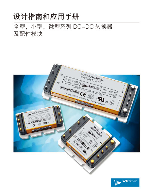
图 2-4 ─ PC / SC 模块警报时间
光耦合器
+IN
PC
4 kΩ PR
-IN
图 2-5 ─ 隔离导通指示器
+OUT
比较器
+IN
+S PC
SC
-S
警报
PR
-OUT
1.00V
–IN
+OUT SC
-OUT
比较器
1.00 V
警报
图 2-6-a ─ 次级导通状态(全型 / 小型模块)
图 2-6-b ─ 次级导通状态(微型模块)
全型、小型和微型系列 DC-DC 转换器及配件模块
全型、小型、微型系列的 DC-DC 转换器是 Vicor 以先 进的设计和制作程序来制造的模块;是公司整体元件功 率解决方案战略中的核心部分 (图 1-1)。该些模块齐备 多样且不受限的标准版本,以至于几乎分不清客制或标 准模块间的界限。
模块的控制器、电磁、开关和封装部件的独特设计,造 就了一个功率密度高达 120 W/in3 (7.3 W/cm3) 的元件, 有三种封装大小:
全型 4.6" x 2.2" x 0.5" (117 x 55.9 x 12.7 mm) 小型 2.28" x 2.2" x 0.5" (57.9 x 55.9 x 12.7 mm) 微型 2.28" x 1.45" x 0.5" (57.9 x 36.8 x 12.7 mm)
该些模块的元件数目只有其原先产品的三份之一。
2. 控制引脚功能及应用
初级控制(PC 引脚)
模块使能 / 失能 可通过将 PC 电压拉到 2.3 V 以下 (相 对于负输入),使模块失能(图 2-1)。这应该通过集电 极开路三极管、继电器或者光耦合器来实现。要使多个转 换器失能,可通过或门二极管配合一个三极管或者继电器 来实现。使用机械开关或者继电器控制 PC 引脚时,务必 使用电容配合(最大 10 nF),以免开关跳动。
VLD可视化设计工具用户操作手册(V1.20版)

许继集团股份有限公司
XJ GROUP CORPORATION CO.,LTD. 2005 年 8 月 31 日
VLD 可视化设计工具用户操作手册
目录 .1 前言 .................................................................................................................................................1 .2 开发环境界面概览..........................................................................................................................1
II
VLD 可视化设计工具用户操作手册
.1 前言
运行 VLD(可视化逻辑设属性)或 者对通过 VLD 工程向导所产生的 VLD 文件(已经成形的装置)进行修改、编译,就可以对 目的装置进行保护逻辑的设计。本文所述装置均指实际安全保护自动装置中的一块 CPU 保护 插件,所产生的保护逻辑均指本插件中所应包含的保护功能。
1
VLD 可视化设计工具用户操作手册
的“元件”、“设置”、“工具”、“运行”等专用的功能菜单组成。具体如下表 1 所示。
菜单
子菜单项
功能简介
名称
文
新建、打开、保存、输出位图、打印、退出
基本工程文件的操
件
作
编 辑 删除、复制、粘贴、读入配置、读入工作区、添加工作区拷贝 完成基本编辑功能
元件
工作区、系统元件、运算元件等(分类)
VAV难点章节

VAV系统安装与调试1.北京华为项目VAV空调系统介绍北京华为项目服务于高级办公和研发,在整个办公场所中设计采用了VAV空调系统,变风量系统是通过改变送入房间的送风量,来调节和控制空调区域温度的一种空调系统。
即体现节能理念,又能降低房间噪音,为科研人员提供良好的办公环境。
本项目中,我公司负责系统的安装和配合VAV BOX设备供应商调试。
本项目的变风量系统采用单风道变风量箱和周边供暖方式的组合,办公区域纵深较大,系统设计上采取了内外分区的方式。
内区设置单风道vavbox送风,通过vavbox供冷或供热;外区设置单风道vavbox 和散热器,通过vavbox供冷或供热,当冬季外区需要供热而内区需要供冷时,空调机运行在供冷模式,外区vav提供冬季最小的送风量,热负荷由散热器提供。
当空调机转换为供热模式时,外区的热负荷尽量由散热器提供,外区vav仍保持冬季最小送风量,当散热器不能提供足够的热负荷时,由外区vav加大送风量供热。
本项目变风量系统由三大要素组成:变风量箱;变风量空调机组;自动控制;Vavbox简图变风量系统的构成示意图2.北京华为项目VAV空调系统的简要构成和控制a)VAV末端的构成和控制DDC主板DDC主板的核心是内置芯片的末端控制器,它通过内置的程序结合输入的参数,可以实现比较复杂的控制规律和实现联网控制。
风速压差传感器风速压差传感器采用若干个全压口和静压孔测定vavbox入口处的动压,该信号为一机械信号,将被送往压力变送器处理。
压差变送器压差变送器将压差机械信号变为压差电信号送到DDC处理,最终计算得到流经vavbox的风量。
风阀驱动器风阀驱动器接受DDC的指令驱动风阀,调节风阀的开度。
房间温控器房间温控器感知房间的温度,并将信号送至DDC进行判断和处理。
压力无关型vavbox的控制逻辑b)变风量空调机ahu的控制在变风量系统中与变风量空调机密切的控制除风阀和水阀的控制,加湿器的控制,压差控制,风机的起停和故障报警等常规控制外,还有最适于变风量系统的变频控制和送风温度控制。
Labview软件设计说明书

Labview软件设计说明书目录1 概述 (3)2 配置要求 (3)3 数据库设计 (3)3.1 User表 (3)3.2 Log表 (3)3.3 Model表 (4)3.4 Testtime表 (4)3.5 Teststep表 (4)3.6 TestProcess表 (4)3.7 TestResult表 (5)3.8 HistoricalQuery表 (5)4 OPC连接 (5)5 软件结构框架 (6)5.1 项目文件管理 (6)5.2 UI界面设计 (6)6 辅助操作 (7)6.1 ActiveX控件注册 (7)7 需改动部分 (8)7.1 IO点位部分 (8)7.2 工艺界面部分 (8)7.3 数据报表部分 (8)1概述本说明书作为LABVIEW软件程序框架说明文件,可作为具体项目程序设计必要说明文件。
内容包括数据库平台、软件结构框架、UI功能设计、OPC连接等,可依据此说明书完成具体项目上位机功能修改及设计。
2配置要求3数据库设计数据库选用WORD Access数据库,共设计有8个表格,每个表格定义如下图所示。
User:帐户密码及权限管理;Log:软件操作日志记录,包括异常操作、软件故障及报警等;Model:产品型号;TestTime:记录设备软件运行时间;TestStep:所有产品及试验项目;TestProcess:用于上位机试验子VI与试验项目关联信息;TestResult:试验结果信息记录;HistoricalQuery:试验过程历史数据记录(特殊要求特殊使用)。
3.1User表User表包含6个字段信息,各字段含义如下图所示。
帐户名称密码权限登陆次数注册时间3.2Log表Log表包含3个字段信息,各字段含义如下图所示。
日志时间帐户名称事件内容3.3Model表Model表包含3个字段信息,各字段含义如下图所示。
产品名称创建时间更新时间3.4Testtime表Testtime表包含3个字段信息,各字段含义如下图所示。
vav空调系统自控设计及实施简介
4. VAV系统之AHU自控设备的配置
通常VAV BOX的冷热风源来自于AHU,且AHU与每个VAV BOX 之间可(应该)有一些联动关系,故需要在AHU处安装一些自控设备 来调节AHU的送风量及送风温度。VAV系统中的AHU控制举例
•有对风机的控制,定静压或变静压控制--------需安装风道静压传感器及 风机变频器。 •对冷/热盘管的控制,定送风温度或变送风温度-------需安装调节水阀及 一些风管温度传感器。 •需对新回风门的控制,使节省能源或保证空调区域空气品质------需安装 电动风门、室内CO2传感器等。 •需要有DDC控制器来采集这些信号,并逻辑运算后发出命令来控制AHU 运行及调节。 •控制AHU的DDC通常必须与每个相关的VAV BOX控制器联网,以实现 对AHU的变静压、变送风温度、空气品质控制及启停控制。
6. VAV系统自控设备的安装
VAV空调系统自控设备的安装关键是VAV BOX及控制设备的安装,
有一些注意事项:
VAV BOX型号避免安装错位,BOX的进出风口连接不要搞错,要给 安装公司交待清楚风口的连接方式 要指明VAV BOX的检修空间及预留尺寸足够的检修孔。 VAV BOX强电电缆与信号电缆要严格分开铺设,BOX电源电缆要有 足够的电流载流能力(尤其是有电加热的BOX)。 所有电缆都要有信号标示套管,信号线色也要统一。 温控面板安装要有统一高度,预埋正确的接线盒。在房间装修完成前 不要安装面板。面板一定要安装在对应的VAV BOX送风区域。 控制通信网络要使用推荐的网络电缆,且连接的VAV BOX控制器数 量不能太多(要有余量)。 安装有BOX处的吊顶板做些标志(如:写上该BOX的编号),便于今 后的调试及维修定位。送风口粘贴飘带。 RJ45网线也要考虑布线距离,如太长可考虑用光纤,也可考虑借用 建筑物内部的综合布线。 风管静压传感器的安装位置。手动风门的安装。
VA-VE手法的运用
SCSP
小豆腐的改善前後比較
改善前(8個Die)
改善後(18個Die)
1999/08月 運管部的
文件 製作
小樣品通關流程
報關行 通關 封箱 機場 放行 出口
結帳
包裝
2000/05月 運管部實施
結帳 包裝 文件 製作
保稅放行簡化流程
保稅放行 出口
通關的機能是為了將貨品運出加工區及 進行報稅的動作,因為三個步驟被合併 了,於是我們得到一個更簡化的事務流 程. 報稅的功能有沒有因為這個流程的簡化 而不一樣呢? 沒有, 所以這就是 VE 的 改善.
石綿事件意示圖
噴漆
電器 用品
石綿板
VE活動特徵
• • • • • 1.使用者(顧客)優先原則 2.機能本位原則 3.創造變更原則 4.團隊設計原則 5.價值提昇原則
提 案 制 度
Q C 小 組 活 動
QCC BKM QIT ….
傳統的產品要打線,所以需要金線
Bumping的產品卻不需要打線
Die Substrate
機能的拆解
動作一 對應的機能一 對應的機能二 對應的機能三 對應的機能一 對應的機能二 對應的機能三
工作流程 (機能提供) VE對象
動作二 …… 零件一
產品 (機能提供)
零件二 ……
2 機能評價
機能評價是為了找出改善的焦點 (優先順序) 1.V 價值(F/C)越低者, 表示投資報酬率太低. 2.成本額度 (C-F) 越高者, 表示太貴了, 機能不 值這個價格.
Square Rectangular VAV终端安装、运行与维护(IOM)手册说明书
SQUARE/RECTANGULAR VAV TERMINALS INSTALLATION, OPERATION &MAINTENANCE (IOM) MANUALReceiving Inspection Prior to removing the shipping materials, visually inspect the packing materials. There should be a black plastic strip wrapped in the clear plastic stretch wrap. If this black plastic strip is missing, the shipment may have been repacked by the shipper and you should make a note of this on the shipping documents and inform the delivering carrier .After unpacking the terminals, check for shipping damage. If any shipping damage is found, report it immediately to the delivering carrier .Always store the product in a clean dry location prior to installation.Units with controls are not recommended for use in ambient temperatures greater than 95º F . For protection of controls, do not store in temperatures above 135ºF .Caution: Do not use the flow sensor , connecting tubing or damper shaft as a lift point. Damage to the components may result.Hanging/Installation Requirements5Unless local building codes require hangers, the basic Square/Rectangular Air Terminals may be light enough to be supported by the ductwork itself. 5Straps or the method prescribed for round duct on the job specification may be used. (See figure 1) 5Trapeze hangers or the method prescribed for round duct on the job specification may be used. (See figure 2)Figure 1 Hanging StrapsMinimum Clearance for AccessSquare/Rectangular Air Terminals require sufficient space to allow servicing of the controls and electric power hook up. Horizontal clearance requirements are dependent upon access panel dimensions which are indicated on the appropriate submittal. For control panel access, a minimum of 18” is recommended. See the appropriate submittal for control panel location.Connecting Duct Work 1. Slip each inlet duct over the inlet collar of the Square/Rectangular Retrofit Air Terminal. 2. Fasten and seal the connection by method prescribed by job specification.3. The dimension of the inlet duct in inches, must be equal to the listed size of the Square/Rectangular Retrofit Air Terminal. The inlet connection of the Square/Rectangular Retrofit Air Terminal is manufactured 1/8” smaller than the listed size in order to fit inside the duct.4. If an inlet air flow sensor is installed, it is recommended the installer provide a minimum of 3 duct diameters of straight duct at the Square/Rectangular Retrofit Air Terminal inlet.5. The outlet end of the Square/Rectangular Retrofit Air Terminal is designed for use with the same duct connections as the inlet.Figure 2 TrapezeField Electrical Wiring 5All field wiring must comply with local building codes and NEC. (ANSI/NFPA 70-2002) 5When Applicable, electrical control and piping diagrams are attached to exterior of Square/Rectangular Retrofit Air Terminal. 5Use copper only conductors. 5Square/Rectangular Retrofit Air Terminal must be properly grounded per NEC 424-14 and 250. 5Always check product label for voltage and current data to determine the proper wire size and over current protection. 5The control cabinet contains live electrical parts. 5Contacting these parts with power applied may cause serious injury or even death. 5The control panel cover must be closed or in place before applying electric power to the Square/Rectangular Retrofit Air Terminal. 5These recommendations are not meant to precluded NEC requirements or applicable local building codes and are the sole responsibility of the installing contractor .ImportantIf equipped with pneumatic controls, the orientation of the Square/Rectangular Retrofit Air Terminal unit is critical. The pneumatic controls must be mounted right side up. The Square/Rectangular Retrofit Air Terminal must be level within + or – 10 degrees of horizontal, both parallel to the air flow and at right angle of air flow. The control side of the Square/Rectangular Retrofit Air Terminal is labeled with an arrow indicating up. Unless otherwise noted, most electric, analog electronic and digital are not position sensitive and may be installed in any orientation. Controls For information on controls provided by other manufactures and installed on the Square/Rectangular Retrofit Air Terminals, contact the local branch or dealer . Installing the Air Terminal in a different location than noted on the Square/Rectangular Retrofit Air Terminal label and building plans, may result in excessive start up labor and is the sole responsibility of the contractor .ImportantSquare/Rectangular retrofit Air Terminals with digital controls, if factory programmed, incorporate specific communication addresses.Inlet Flow Sensor Square/Rectangular Retrofit Air Terminals are shipped with factory installed (where applicable) pressure differential inlet flow sensors in the primary inlet. See figure 3 for calibration curve and K belingSquare/Rectangular Retrofit Air Terminals are shipped from the factory with multiple information labels.Control Sequence Label: Affixed to the exterior of the Square/Rectangular Retrofit Air Terminal casing. Displays piping/wiring diagram, control sequence number and any optional components.Terminal I.D. Label: Affixed to the exterior of Square/Rectangular Retrofit Air Terminal. Shows tagging, representative name, sales order number , applicable certifications, model number, Made in USA, any applicable electrical data and UL compliance markings.AHRI Certification Label: Identifies applicable industry test standard and certifies Air Terminal is in compliance.Orientation Label: Identifies the proper air flow direction and top of Square/Rectangular Retrofit Air Terminal.TroubleshootingInvestigating Noise Complaints 5Noise from a Square/Rectangular Retrofit Air T erminal can be due to a variety of conditions and can be difficult to eliminate. 5The first step is to isolate the type, source and direction.5Generally noise heard at the air outlet is considered a discharge type. 5Noise heard through the ceiling is considered radiated noise. 5For detailed information concerning noise transmission in buildings, refer to AHRI Standard 885-2008, “Procedure for estimating occupied space sound levels in the application of Air Terminals and air outlets”.Discharge Noise 5This is usually caused by high static or little to no internal duct lining downstream of the Square/Rectangular Retrofit Air Terminal. 5It can sometimes be caused by air outlet itself. 5Air outlet generated sounds can be reduced by reducing flow or increasing an outlet size. 5Reducing static pressure, flow or adding additional downstream attenuation materials will reduce discharge sounds from the Air Terminal.Radiated Noise 5Radiated noise is most commonly associated with Fan Powered Terminals.Figure 3。
Vijeo-Designer培训手册
目录一、系统需求----------------------------------------------------------------------- 1二、软件许可----------------------------------------------------------------------- 2三、如何开发工程---------------------------------------------------------------- 3四、创建工程--------------------------------------------------------------------- 44、1 关于工程-------------------------------------------------------------------- 44、2 新建工程-------------------------------------------------------------------- 5五、使用工程--------------------------------------------------------------------- 135、1打开现有工程----------------------------------------------------------- 135、2新建画面--------------------------------------------------------------- 15六、使用简化操作----------------------------------------------------------------- 176、1使用工具窗口------------------------------------------------------------ 176、2设置工具窗口视图----------------------------------------------------- 17七、保存关闭和退出工程----------------------------------------------------- 217、1 保存工程----------------------------------------------------------------- 217、2 工程另存为----------------------------------------------------------------- 237、3 关闭工程----------------------------------------------------------------- 237、4 退出工程----------------------------------------------------------------- 25八、绘制图形-------------------------------------------------------------------------- 268、1图形对像------------------------------------------------------------------- 26九、图形对像功能------------------------------------------------------------------ 299、1调色板---------------------------------------------------------------------- 299、2使用调色板选择颜色---------------------------------------------------- 309、3使用吸管工具选择颜色------------------------------------------------- 301. 系统需求下列表格列出了Vijeo-Designer和Vijeo-Designer Runtime的系统需求。
Vivado 设计流程指导手册 (含安装流程与仿真)

Vivado设计流程指导手册——2013.4Vivado设计分为Project Mode和Non-project Mode两种模式,一般简单设计中,我们常用的是Project Mode。
在本手册中,我们将以一个简单的实验案例,一步一步的完成Vivado 的整个设计流程。
一、新建工程1、打开Vivado 2013.4开发工具,可通过桌面快捷方式或开始菜单中Xilinx Design Tools->Vivado 2013.4下的Vivado 2013.4打开软件,开启后,软件如下所示:2、单击上述界面中Create New Project图标,弹出新建工程向导,点击Next。
3、输入工程名称、选择工程存储路径,并勾选Create project subdirectory选项,为工程在指定存储路径下建立独立的文件夹。
设置完成后,点击Next。
注意:工程名称和存储路径中不能出现中文和空格,建议工程名称以字母、数字、下划线来组成。
4、选择RTL Project一项,并勾选Do not specify sources at this time,勾选该选项是为了跳过在新建工程的过程中添加设计源文件。
点击Next。
5、根据使用的FPGA开发平台,选择对应的FPGA目标器件。
(在本手册中,以Xilinx官方开发板KC705为例,Nexys4开发板请选择Artix-7 XC7A100TCSG324-2的器件,即Family和Subfamily均为Artix-7,封装形式(Package)为CSG324,速度等级(Speed grade)为-1,温度等级(Temp Grade)为C)。
点击Next。
6、确认相关信息与设计所用的的FPGA器件信息是否一致,一致请点击Finish,不一致,请返回上一步修改。
7、得到如下的空白Vivado工程界面,完成空白工程新建。
二、设计文件输入1、如下图所示,点击Flow Navigator下的Project Manager->Add Sources或中间Sources中的对话框打开设计文件导入添加对话框。
江森VAV空调自控培训手册
阿里中心空调自控培训手册培训时间:___________________________ 培训人:_____________________________ 培训参加人员:_________________________________________________________________ _______________________________________________________________________________ _______________________________________________________________________________ _______________________________________________________________________________ _______________________________________________________________________________ 培训参加人员单位:_____________________________________________________________ 培训内容:一、自控系统的登录与注销。
1)系统登陆。
正常启动电脑控制主机,双击鼠标打开屏幕中图标,在弹出的对话框中双击“阿里中心空调自控”后弹出登陆对话框,输入对应的账号与密码。
输入完成后鼠标左键点击Login进入系统Username:(此处填写账号)Password:(此处填写密码)2)系统注销。
注销系统,请点击用户界面菜单栏的Logout 按钮;退出系统,请点击用户界面菜单栏的Exit 按钮。
注:如果您正在显示区域中进行编辑操作,Metasys 软件将会终止注销或退出程序并显示对话框,提醒您在编辑模式中无法注销或退出。
您在注销或退出系统之前必须通过保存或取消变化来退出编辑模式二、用户界面1.用户界面包含四个区域:菜单栏、显示区、导航区及状态栏。
(WI-FM-004)VAV操作手册

北京XXXXXXXX管理服务有限公司广州分公司XXXXXXXX南方工厂B区综合设施管理项目部VAV操作规程XXXXXXXX/WI目录1.目的 (3)2.范围 (3)3.定义 (3)4.职责 (3)5.程序 (3)6.相关文件......................................... 错误!未定义书签。
7.相关记录......................................... 错误!未定义书签。
1. 目的指导运维对VAV空调进行正确的操作及检查,保障VAV的正常、高效、节能运行,为客户的生产和办公提供符合KPI要求的环境。
范围本程序适用于XXXXXXXX XXXXXXXX南方工厂B区项目。
2.定义无3.职责暖通工程师1.负责制定设备操作程序;2.制定教育培训资料及培训计划,并对运行和维护人员进行定期培训与考核;3.处理设备重大故障,制定重大异常故障的改善方案及执行。
BMS1.带领本班组技术员对设施运行进行监控及时发现问题、解决问题,并按照汇报程序及时向上级汇报;2.监控设备运行情况,确保它们在高效方式下运行。
运行班长1.监督运行技术员每日例行检查的完成情况,确保按照部门规定对设备设施进行日常检查;技术员1.严格执行本程序,确保信息及时有效地传递给运行值班长及主管;部门经理:1.负责与客户沟通和协调。
4.操作程序启动前检查:1.确认风阀、水阀是否打开。
2.确认机组配电均在正常送电状态,无故障报警。
VAV空调风柜远程开启:1.现场将控制柜打到“自动”状态。
2.进入所需开启的VAV界面点击“开启”3.在空调控制界面:“送风温度设定”控制水阀开度,“送风压力设定”制控送风风机频率。
”回风压力设定“制控回风风机频率。
“排风阀开度”“新风阀开度”“回风阀控制“采用手动调节。
VAV 空调风柜就地开启:1.现场将控制柜打到“手动”状态。
2.在现场控制柜直接按“开启”远程停机:1.现场将控制柜打到“自动”状态。
VAV变风量空调系统的设计与分析
VAV变风量空调系统的设计与分析作者:刘辉来源:《大观周刊》2012年第33期中图分类号:TB 文献标识码:A 文章编号:1008-925X(2012)O8-0106-02摘要:本文简要介绍了变风量空调系统,对此系统的设计要点及控制要求作了说明;并把通过调研和有关资料收集的设计实例介绍给大家。
希望同行们共同关心、讨论、研究VAV系统的设计及应用。
关键词:变风量空调系统设计控制应用变风量空调系统(VAV)是一种通过改变送风量来调节室内温湿度的空调系统。
变风量空调系统20世纪60年代起源于美国,特别是进入70年代以来,以石油危机为标志的世界能源危机更加促使一些发达国家在各行各业中研究和推广节能技术,自80年代开始在欧美、日本等国得到迅速发展,最重要的原因是其巨大的节能优势。
经过十几年的普及和发展,目前变风量空调系统已占据了欧、美、日集中空调系统约30%的市场份额,并在世界上越来越多的国家得到应用。
1、变风量空调系统(VAV)简介1.1变风量空调系统的含义和组成变风量空调系统是利用改变进入空调区域的送风量来适应区域内负荷变化的一种空调系统。
在设计时充分考虑了瞬时负荷及内外区的热平衡,系统设计是真正基于逐时负荷的设计,可以根据需要随时调节分配到各个区域内的送风量和供冷量(供热量)。
系统总送风量为各时段中所有区域要求风量之和的最大值,而不是所有区域要求风量最大值之和。
前者通常只占后者的70%~90%,因此变风量空调系统可以显著减少系统的总送风量。
在现代建筑尤其是现代高层建筑的空调系统设计中,由于负荷的内外区特性差异大,内区通常表现为全年冷负荷,而外区则既有冷负荷又有热负荷。
变风量空调系统通过回风的混合可以实现能量在区域之间的流动,内区的一部分得热可以转移到外区。
这就是所谓热平衡。
变风量空调系统是由空气处理机组、新风/排风/送风/回风管道、变风量末端、房间温控器和必要的自动控制元件组成。
其中变风量末端是该系统的最重要部分。
迪尔·高效终端产品单区VAV解决方案说明书
Trane Family of Terminal ProductsIt’s time to take another look at the terminal. As your partner, Trane® understands it takes more than a concept to design an effective HVAC system. Between cost and code compliance—not to mention comfort, acoustics and efficiency—the complicated priorities can be challenging to satisfy.The Trane family of terminal products has been redesigned from the inside out, with innovative high-efficiency upgrades guaranteed to fulfill virtually any building’s requirements without compromising your needs. Now, these terminal units come standard with an exclusive Trane electronically commutated motor (ECM)—an industry first. Integrated with the industry’s first factory programmed variable speed controller, the single-zone variable air volume (VAV) solution improves efficiency by up to 66 percent compared to other motor options.Single-source solutionFrom chillers to compressors, the complete line of variable speed Trane HVAC solutions are designed to work together to deliver exceptional performance and value. These high-efficiency systems with flexible configurations can be the perfect fit for your building.Fan CoilA Trane® UniTrane® fan coil is anin-room unit composed of a fanand chilled or hot water coils.Trane also offers vertical unitsspecifically intended for high-rise applications. Fan coil units areideal for hotels, condominiums, dormitories and apartments. Trane® Force-Flo® cabinet heaters are high-capacity forced-air fan coil units for entryways and corridors in large office buildings, schools, hospitals and dormitories.Unit VentilatorsTrane unit ventilator operates onthe same principles as the fancoil but is tailored specifically forschools with a sturdy institutionaldesign and an integrated airside economizer. Our unit ventilator unitsare an especially effective solution forK-12 classroom renovation projects.Blower CoilsA Trane blower coil is an entrylevel air handler for chilled water or refrigeration systems with ductedair distribution. Applicationsinclude schools, hospitals, offices,retail stores and stadiums.2Single-zone VAV SystemSingle-zone variable air volume (VAV) is a high-efficiency system in which the motor speed and air volume automatically adjust in response to a space’s needs. Those spaces—in which occupancy varies—include classrooms, office buildings, gymnasiums, dormitories and barracks.Single-zone VAV offers substantial operating savings over a constant volume system because a high-efficiency motor-driven variable fan speed can be the most energy-efficient way to address partial load conditions. Single-zone VAV lowers operating costs because of the efficiency gains that come from the ability to operate at low speeds for partial loads.A single-zone VAV system can improve comfort for building occupants through:Temperature stability variable speed technology gradually changes fan speed, which reduces temperature swings.Quiet operation variable speed units run at the lowest fan speed necessary and move up and down slowly between speeds. This soft ramp capability means fewer audible changes and a substantial5-to-8-decibel reduction in system noise. Dehumidification operating at lower speeds for more time improves dehumidification, a key factor in IAQ and comfort.Trane® ECM terminal units integrated with the UC400 unit controller offers the only factory-commissioned single-zone VAV solution in the industry.Building LifeTrane knows that careful attention to the unique needs of a building can improve life of the equipment, controls and the HVAC systems.This solutions-oriented commitment to delivering exceptional performance fosters an environment that has a positive impact on the lives of the people within it.Single-zone ConfigurationIn a single-zone VAV system, the temperaturesensor in the zone is used to vary the airtemperature and the air volume in order tomaintain the desired set point.EAOA SARASPACETerminal TransformedTerminal units shouldn’t be an industry afterthought. Trane ® understands these are critical system components, with special consideration given toevery design and technical specification to transform our family of terminal solutions into a high-performing driver for your building’s efficiency. Whether you’re concerned with occupant comfort or system design, Trane can work with you to find the right solution. Innovations in ECMTerminal products were updated from conventional permanent split capacitor (PSC) motors to our exclusive new electronically commutated motor(ECM), making Trane the only manufacturer currently offering environmental conditioning systems (ECSs) as standard technology on all terminal products.Real-time FeedbackVelociTach ™ is our ECM control board that features aTrane exclusive LED screen to provide real-time feedback to installers and maintenance staff. This eliminates the inconvenience of using a separate service tool.Single-zone VAVTrane terminal ECM units integrated with the UC400 unit controller are the industry’s first factory-commissioned single-zone VAV solution, with automated and optimized motor speed adjustments to meet a space’s heating or cooling needs.Met exerum dolupta dolenda autae etus de num cum rem rerrum re tem rateControl Board Benefits Enhances serviceability and improves response time for maintenance staff. Allows maintenance to monitor performance and maximize efficiency.Eliminates cost of additionalcomputer hardware and software. Reduces the time needed tobalance the unit during installation.Trane ECMs ...Giving you ...Have sealed bearings and completelyenclosed construction Extended motor life and lower maintenance costs over the life of the systemOptimize performance at every speed Dramatically enhanced efficiency, with energy savings up to 66 percent Have fewer moving parts and are much Lower maintenancesystems with lower totalTerminal TransformedTrane® developed innovative control algorithms that maximize the performance and efficiency for each of the units under all operating conditions.Only Trane terminal products are available with factory mounted, wired and programmed Tracer® unit controllers, providing unmatched system integration and performance optimization.Flexible ConnectivityHigh-efficiency terminal products—unlike competitive offerings—allow for building connectivity through multiple control options. Preprogrammed Air-Fi®wireless controls can offer plug-and-play connectivity, as well as individual guest control.Tracer UC400-B Unit ControllerThe UC400-B single-zone VAV controller maximizes fan speed while reducing energy consumption by delivering only the airflow necessary to address the space load. This programmable controller’s functions include:• Random start• Warm-up, pre-cool• Freeze avoidance• Built-in dehumidification• Auto fan speed adjustment Controlled CostsThe lowest total cost of ownership in the industry makes the new Trane high-efficiency terminal unitsa value-added asset to any building’s HVAC system.Separation InnovationWe separated the Trane ECM from the VelociTach™motor control board, and added an LED display and manual interface.This delivers the convenience of a visual status report and the ease of push button adjustments, facilitating optimal performance and simplifying serviceability.Tracer UC400-B Unit Controller5Understanding the UpgradesThe terminal products upgrade is more revolution than redesign. Rather than incremental improvements, we took a technological leap forward and elevated the industry standard for this product class.We leveraged the synergy of the new technology suite to produce dramatic improvements in easeof installation, cost of ownership, acoustics and temperature control.Streamlined InstallationUnits, unit controls and piping packages are installed, configured and tested during assembly.A factorycommissioned system makes the job-site installation a streamlined plug-and-play process and ensures long-term trouble-free operation.Quiet OperationSoft ramp technology slowly ramps motor speeds up and down to address the space load and eliminates the distracting noise associated with units turning on and off. And because the moderated air flow achieves the same comfort levels as running at full capacity, variable units are 5 to 8 decibels quieter than traditional three-speed models.Continuous ComfortInnovative tempering algorithms in the UC400 controller eliminate the typical temperature variations that cause occupants discomfort. This discharge air temperature control means your space reached the desired set point more quickly and the temperature maintenance is more stable. Superior PerformanceECM is a high-efficiency programmable motor technology. Motors require less maintenance, are more reliable and have longer service life. They can be performanceoptimized at any speed, dramatically increasing energy efficiency over conventional three-speed PSC motors.ECM has significant efficiency gains over PSC20406080100Full-loadEciency,%Brushless DC (ECM)Permanent Split Capacitor ACShaded Pole ACNo Compromise SolutionThe features you want. The technology you need.Trane® asked customers what they need in a terminal unit. Then we built their feedback into the new designs. The result is a flexible line of high-efficiency solutions that meet all of your new construction and renovation needs. No compromise necessary.Universal CompatibilityTrane terminal units offer flexible solutions for variable speed operation through compatibility with existing thermostats and controllers.The open communication protocol of the Tracer® UC400 supports seamless integration at the building system or equipment level through BACnet communication.With a smart controls retrofit solution, there are no limits to what Trane can do for you.Trane Select AssistHigh-efficiency terminal products are now available through Trane Select Assist. This web-based program improves efficiency and accuracy in your selection process, and enhanced outputs and reports are intuitive and easy to read. With just a few clicks, the program’s guided selections eliminate time spent setting common fields across multiple units. Trusted PartnersYour new Trane system is built on a foundation of expertise earned with a century of hard work. We bring commitment to industry leadership, product innovation and superior performance, and we are focused on providing comprehensive solutions you can count on.Total Cost ofOwnership Efficiency Serviceability Flexibility Acoustics ComfortTrane ExclusiveECM StandardAdvanced ControlsPlug & PlaySoft RampDischarge AirTemperature ControlReal-time FeedbackReduced FLA7Learn more at Trane – by Trane Technologies (NYSE: TT), a global climate innovator – creates comfortable, energy efficient indoor environments through a broad portfolio of heating, ventilating and air conditioning systems and controls, services, parts and supply. For more information, please visit or .© 2021 Trane. All Rights Reserved. All trademarks referenced in this document are the trademarks of their respective owners.UNT-SLB030-EN09/29/2021。
VAV系统设计和调试
VAV 系统设计应用中,对于系统噪声的防控是设计工作 的要点之一。VAV 系统运行的噪音来源主要是空调处理机、排 风机以及风阀、封口以及弯头部位。针对噪音来源,在设计施 工中要对处理机的型号与技术参数进行明确,通过对设备风 机运行、传动方式的分析,选取噪音相对较小的处理机。对于 管道噪音问题来说,在设计中可以于管道中设置复合式消声 器,有效降低和消除系统运行时产生的中低频噪音。
表1vav系统优点对比表类型性能能耗独立性灵活性全空气系统特性vav系统传统系统考量同时使用情况节约风机运行能耗和风机装机容量能耗较大可以根据室内温度与设定值的偏差来调节送风量独立性较差易于改扩建尤其适用于格局多变的建筑灵活性不足属于全空气系统具有全空气系统的部分优点容易产生盘管凝水问题和霉菌滋生等问题3vav系统设计要点分析31变风量末端选型在vav系统设计当中根据工程环境工程规模以及技术要点等因素系统地综合地对变风量末端设备进行选取与应用是系统设计中的重要环节也是保证系统运行质量与效率的重要因素1
中小企业管理与科技
Management &Technology of SME
VAV 系统设计和调试
The Design and Debugging of VAV System
冯玉刚
(成都市青羊区宁夏街 136 号附 4 号,成都 610000) FENG Yu-gang
( No.136-4, Ningxia street, Qingyang District, Chengdu, Chengdu 610000, China )
China has been greatly developed. Continuously improving the air conditioning design system and the debugging technology is an important way
变风量空调系统设计
变风量空调系统设计孙宁清华大学热能工程系(100084 北京清华大学热能系空调教研组)摘要讨论了变风量(VAV)空调系统设计中的新风、噪声、气流组织、房间正压、末端装置的选择以及系统控制方法等几个主要问题,并提出一些建议,供参考。
变风量(VAV)系统简介变风量系统(Variable Air Volume System, VAV系统)本世纪60年代诞生在美国。
VAV技术的基本原理很简单,就是通过改变送入房间的风量来满足室内变化的负荷。
由于空调系统大部分时间在部分负荷下运行,所以,风量的减少带来了风机能耗的降低。
VAV系统追求以较少的能耗来满足室内空气环境的要求。
VAV系统出现后并没有得到迅速推广,当时美国占主导地位的仍是定风量(CAV,Constant Air Volume)系统加末端再加热和双风道系统。
西方70年代爆发的石油危机促使VAV系统在美国得到广泛应用,并在其后20年中不断发展,已经成为美国空调系统的主流,并在其他国家也得到应用。
VAV系统有如下优点:a.由于VAV系统通过调节送入房间的风量来适应负荷的变化,同时在确定系统总风量时还可以考虑一定的同时使用情况,所以能够节约风机运行能耗和减少风机装机容量。
有关文献介绍,VAV 系统与CAV系统相比大约可以节能30%-70%,对不同的建筑物同时使用系数可取0.8左右。
b.系统的灵活性较好,易于改、扩建,尤其适用于格局多变的建筑,例如出租写字楼等。
当室内参数改变或重新隔断时,可能只需要更换支管和末端装置,移动风口位置,甚至仅仅重新设定一下室内温控器。
c.VAV系统属于全空气系统,它具有全空气系统的一些优点,可以利用新风消除室内负荷,没有风机盘管凝水问题和霉菌问题。
图1是一个典型的单风道VAV空调系统。
在这个系统中,除了送、回风机、末端装置(VAV Terminal)、阀门及风道组成的风路外,还有4个反馈控制环路(室温控制、送风静压控制、送回风量匹配控制及新排风量控制)。
VAV空调系统初探_李克欣
VAV 空调系统初探上海大方空调有限公司 李克欣m 华东建筑设计院 叶大法 杨国荣广电部设计院 吴纯举上海市建筑设计院 寿炜炜浙江省建筑设计院 张 力提要 介绍了VAV(Variable Air Volume,变风量)空调系统的特点、构成、系统设计、控制方法,并给出了在上海的两个实例。
关键词 变风量空调装置 设计 控制 定静压 变静压Composition and control of the VAVair conditioning systemB y L i K exin,Y e D afa,Y an g G uorong,Wu Chun ju,Shou W eiwei and Zhang LiAbs t r ac t Des c r i be s gener al advant ages ,c ompo si t i on,des ign and c ont r ol of t he VAV (Var iabl e A i r Vol ume )ai r c ondi t i oni ng s y s t em,and pr ovi de s t wo exampl es o f ac t ual pr oj ec t s bui lt i n S hanghai.m 200003上海市南京西路88号6楼Keywor ds f an power ed box,des i gn,c o nt r ol ,c ons t ant s t at i c pr es sur e,vari abl e st at i c pr es sur eVAV (V ariable Air Volume)空调系统具有舒适、节能等特性,在日美等国或境外设计的我国国内建筑中大量采用,已引起我国空调研究、设计部门及设备厂家的很大兴趣。
VAV 空调系统在国外有多年设计运行实绩。
随着国内办公大楼智能化程度的提高,要求相应的空调系统更加舒适、安全和节能,同时具备智能化功能。
VAV变风量系统 方案描述

x x项目变风量V A V自控系统技术方案1. 方案描述1.1 变风量(VAV)系统的组成常规设计中,变风量空调系统主要包括变频空调机组和末端风箱,末端风箱通过改变对空调制冷/加热区域的送风量调节室内温度,而变频空调机组主要根据送风量的变化调整风机变频器的受电频率,从而在满足末端风量的需求的前提下减少风机的能耗。
同时,为了更好的维持室内微正压的要求,保证室内空气质量,变风量空调系统会要求对室内的新风和排风量都要进行连锁变频控制。
本项目变风量空调系统根据实际建筑的特点设计,主要包括以下部分:位于首层大堂、9-70层、71层的变风量末端2244台(VAV BOX)位于负1夹层、71夹层的变风量空调机组(VAV AHU)位于23层、25层、49层、51层的带热回收组合式新风处理机组(VAV PAUR) 位于69层的带热回收热泵式溶液调湿新风处理机组(VAV HPAU)1.2 变风量空调机组控制方案①定静压控制方案当VAV末端风门改变开度后,会影响整个风道的静压,风机通过改变风量以满足风道系统的静压要求。
根据招标文件提供的设计方案,变风量空调机组的风量调节采用定静压控制方案,通过风机变频器来完成。
风管静压的控制点一般放在主风道距风机出口的2/3处。
定静压控制方案属于传统的变风量空调系统的调节方案,实际使用时常常存在如下问题:·设定值不确定问题定静压控制方案必须在控制系统中对风道静压的设定值进行确定,这种确定往往按设计院提供的设计数据或凭经验设定。
而实际的风系统的阻力特性往往与当初的设计系统存在较大的差别,当静压设定值偏大时,VAV末端装置的风门往往不能全开,浪费能耗;当静压设定值偏小时,远端的VAV末端装置即使风门全开也达到不了房间的温度要求。
·多支管问题当变风量空调机组带有多支路VAV末端装置时,静压传感器布置的位置显得比较复杂,可能需要在很多分支风管上布置静压传感器,然后选取最小值或平均值进行变风量控制依据。
VAV控制器技术说明
VAV控制器技术说明————————————————————————————————作者:————————————————————————————————日期:2西安咸阳国际机场二期扩建工程T3A航站楼空调设备采购项目(1包)VAV控制器技术说明陕西百盛动力设备工程有限公司2010年9月致西部机场集团有限公司招标办公室:西安咸阳国际机场二期扩建工程T3A航站楼空调设备采购项目(1包)中共有V A V末端129套(此数量为招标文件中的数量),其中单风道型V A V末端122套,带热水盘管再加热的风道型V A V控制器7套,该标段中标单位陕西百盛动力设备工程有限公司在V A V末端中所配的V A V控制器为西门子的V A V控制器,由于V A V末端控制涉及到与变风量空调机组的联动控制,所以本技术文件就V A V末端所配的V A V控制器的详细技术参数予以说明,以便其它相关专业参考,技术说明如下:1、V A V末端的说明1.1、单风道型V A V末端单风道型V A V末端所包括的设备及元件:V A V 末端箱体、平均空气流速传感器、风量调节阀,变压器,西门子BACnet ATEC 变风量控制器550-440(风阀执行器一体式V A V控制器),单风道型V A V末端不包括的内容:室内温度传感器,该设备不在空调1包中,建议由楼宇自控专业采购,V A V控制器需依据室内温度传感器采集的数据来控制风量调节阀开度,从而实现V A V末端的变风量控制,维持室内温度在设定范围内。
单风道型V A V末端型号规格:设备名称型号及规格VAV控制器数量单位备注变风量调节器TVS-A/125 L=54~540m³/h 550-440 2 台带24VAC变压器变风量调节器TVS-A/160 L=90~900m³/h 550-440 42 台带24VAC变压器变风量调节器TVS-A/200 L=144~1458m³/h 550-440 28 台带24VAC变压器变风量调节器TVS-A/250 L=216~2214m³/h 550-440 15 台带24VAC变压器变风量调节器TVS-A/315 L=378~3690m³/h 550-440 9 台带24VAC变压器变风量调节器TVS-A/400 L=612~6048m³/h 550-440 17 台带24VAC变压器变风量调节器TVS-B/125 L=54~540m³/h 550-440 2 个带24VAC变压器变风量调节器TVS-B/160 L=90~900m³/h 550-440 6 个带24VAC变压器变风量调节器TVS-B/250 L=216-2214m³/h 550-440 1 个带24VAC变压器1.2、带热水盘管再加热的风道型V A V末端带热水盘管再加热的风道型V A V末端所包括的设备及元件:V A V 末端箱体、热水盘管,平均空气流速传感器、风量调节阀,24V AC变压器,西门子BACnet ATEC 变风量控制器550-445(风阀执行器一体式V A V控制器),带热水盘管再加热的风道型V A V末端不包括的内容:室内温度传感器,热水加热盘管的电动调节阀及执行器。
- 1、下载文档前请自行甄别文档内容的完整性,平台不提供额外的编辑、内容补充、找答案等附加服务。
- 2、"仅部分预览"的文档,不可在线预览部分如存在完整性等问题,可反馈申请退款(可完整预览的文档不适用该条件!)。
- 3、如文档侵犯您的权益,请联系客服反馈,我们会尽快为您处理(人工客服工作时间:9:00-18:30)。
17
EXCONTROL 䰆⟚ࠊ
18
⡍⅞ᑨ⫼
19
ᑇ㸵䯔⇨ᆚ䯔
20
䰘ӊ
21
᠓䯈⏽఼
22
ࠊㄪ⬹
23
ࠊ䚼ӊ
24
㋏㒳䲚៤
27
䆒䅵߭ޚ
28
ᡔᴃ᭛ӊ
29
䆒䗝ൟ
30
乍Ⳃᅲᮑ
32
䇗䆩
33
ḋᵓᎹ
35
亢䞣䇗㡖䯔ⱘ⫳ѻᷛᅮ
2
••••••
Ӵᡓ㒣偠ϡᮁ߯ᮄ
ཹᗱぎ䇗䆒—㧹䗴ᅸݙ㟦䗖⦃๗ⱘ⧚ᛇ䆒
䗮亢ぎ䇗㋏㒳⫼Ѣ䇗㡖ᅸⱘݙぎ⇨ક䋼ঞ⏽ǃᑺˈ ֱ䆕ᅸ⦃ݙ๗⒵䎇⌆ᷛޚEN13779ⱘ㽕∖DŽ
߽⫼䖭Ͼॳ⧚䖯㸠⌟䞣ᯊˈ⇨⌕ϡⳈৠӴᛳ఼㾺ˈ 䖭ህᛣੇⴔӴᛳ఼ϡᯧফ∵ᶧDŽϡ䖛ˈҡ᳝ϔ⚍䳔㽕⊼ ᛣˈ࣪ᄺ㥃કᇚ䗮䖛ᠽᬷ䖤ࡼ䖯ܹব䗕఼ˈৠ䱨㝰ҹঞ ⌟䞣ᇣᅸ㾺ˈѻ⫳ডᑨDŽ✊㗠↨䍋ࡼᗕ⌟䞣ᮍᓣˈ䖭 ϔ䖛ᓩ䍋ⱘॅᆇ㽕ᇣᕫDŽ
U
. V
~U
. V
U
. V
~
U
. V
7
••••••
亢䞣ࠊ
㒑Ӻֱ䰽ὐˈ㒑Ӻˈᖋ
᠓䯈ݙг᳝㡃དⱘぎ⇨ક䋼
g䰤ᅮњ᳔亢䞣ˈϡҙৃҹᇚय़䰡ాໄࠊ 䆒䅵ᷛޚПˈݙ䖬ৃҹ䙓⦄ߎܡĀ亢ᛳā
gᥦ亢гৃҹᣝVAVᮍᓣ䖤㸠
य़Ꮒব䗕఼ⱘ⌟䞣ॳ⧚
ᇚय़Ꮒ䕀বЎ⬉ࡼ⇨ࡼֵোˈ⫼Ѣࠊ亢䞣DŽ⬉ᄤܗ ӊḍࡼᗕय़Ꮒ䴭ᗕय़Ꮒॳ⧚⌟䞣亢䞣DŽ
ࡼᗕय़Ꮒ⌟䞣 䞛ḋ⇨ԧ㒣ᮕ䏃⌕䖛य़Ꮒব䗕఼DŽব䗕఼ⱘ㒧ᵘབϔϾ ᇣൟⱘ䗳ᑺ⌟䞣ㅵDŽব䗕఼ݙ᳝ϔϾࡴ⛁ܗӊˈ䆹ࡴ ⛁ܗӊᇚᦤկϢ亢䞣Ⳍ݇ⱘ⬉ֵোDŽ䖭ᰃ⬅Ѣᔧ⌕㒣ব 䗕఼ⱘ⇨⌕䗳ᑺࡴˈࡴ⛁ܗӊⱘᬷ⛁䞣гᇚࡴDŽ 䞛ḋぎ⇨Ϣᘏ亢䞣៤↨՟ˈ㒣䖛ᷛᅮৢˈৃҹᇚ⌟䞣ֵ ো䕀࣪Ўᘏ亢䞣ˈᑊ䕧ߎϢ亢䞣㒓ᗻⳌ݇ⱘ⬉य़ֵোDŽ
亢䞣㋏㒳ৃҹᅲ⦄䖭Ͼ㽕∖ˈֱ䆕䗕ࠄ↣Ͼ᠓䯈 ऎ
ඳ ⱘ亢䞣Ϣ㓈ᣕᅸݙ㟦䗖⦃๗᠔䳔亢䞣Ⳍ䗖ᑨDŽ
亢䞣ࠊ䳔㽕䜡⬉ࡼ⇨ࡼⱘࠊ䚼ӊDŽ᭄ᚙ
A
މϟˈᰃḍ᠓䯈⏽ᑺ⹂ᅮ亢䞣ᇣDŽᔧ✊ˈгৃ⬅Ϣ
ᅸݙぎ⇨ક䋼Ⳍ݇ⱘখ᭄⹂ᅮ䗕亢䞣DŽ
B
ব亢䞣 䗳ࠊ
ક䋼 㡖
㋏㒳 㛑
ぎ⇨
20ᲇ
亢ᴎ䕀
A TVRൟব亢䞣䇗㡖఼ B RNൟᅮ亢䞣䇗㡖఼
9
••••••
᠓䯈⏽ᑺࠊ
᠓䯈⏽ᑺࠊ
••••••
VAV㋏㒳䞛⫼І㑻ࠊᮍᓣࠊ᠓䯈⏽ᑺDŽ᠓䯈⏽ ఼ᑊϡⳈࠊ䗕亢䯔ˈ㗠ᰃᬍব亢䞣ࠊಲ䏃ⱘ䆒 ᅮؐDŽ亢䞣া㛑᳔ᇣ᳔ؐؐП䯈ব࣪ˈ䖭᳝߽ Ѣֱᣕ᠓䯈⏽ᑺ〇ᅮˈֱ䆕ᭈϾぎ䇗㋏㒳ℷᐌ䖤㸠˖
g亢ㅵय़⊶ࡼϡᕅડ᠓䯈⏽ᑺ g⬅Ѣ䰤ᅮњ᳔ᇣ亢䞣ˈ䖭ḋेՓ᳔ᇣދ䋳㥋ᯊˈ
ᅮ亢ᴎ䕀䗳亢䞣䇗㡖䯔 ϡᖙ⌟䞣↣Ͼᬃㅵⱘ亢䞣ˈা乏䆒ᅮ䕗催ⱘ亢ᴎ䕀䗳ˈ ᦤկ䎇ⱘय़༈ˈֱ䆕᠔᳝䇗㡖䯔ℷᐌᎹⱘय़༈ˈᑊ 乘⬭䖛Ⓒ఼ⱘ㒜䰏ࡴDŽ
ব亢ᴎ䕀䗳ᑇ㸵䯔 䇗㡖ᑇ㸵䯔ᑊࠊ亢ᴎ䕀䗳ҹ㓈ᣕ亢ㅵⱘݙय़ˈҢ㗠 ֱ䆕亢䞣ᘦᅮDŽᔧ䖛Ⓒ఼䰏䕗ᇣᯊˈⳌᑨⱘ亢ᴎ䕀䗳 гህ䕗ԢDŽ
ব亢ᴎ䕀䗳亢䞣䇗㡖䯔 䆹㋏㒳ᔶᓣӬ⚍᳔ˈϡᖙҎᎹᣕ㓁䇗ᭈ㋏㒳ˈϨ㛑ᅲ ⦄㒣⌢䖤㸠DŽ䳔∖亢䞣থ⫳ব࣪ᯊˈা䳔㞾ࡼᬍব亢䞣 䇗㡖䯔ⱘ䆒ᅮؐDŽ
8
••••••
亢䞣ࠊ
••••••
⬉ࡼ⇨ࡼᓣব亢䞣ࠊ
亢䞣ࠊ䞛⫼䯁⦃ࠊˈे˖⌟䞣ˉ↨䕗ˉࠊDŽय़Ꮒ ব䗕఼⌟䞣ᅲ䰙亢䞣ؐˈ㗠亢䞣䆒ᅮؐ䚼ߚഎড়ϟ ᰃ⬅᠓䯈⏽఼⹂ᅮⱘDŽࠊ఼ᇚᅲ䰙ؐϢ䆒ᅮؐ䖯㸠 ↨䕗ˈབᵰϸϾؐߎ⦄أᏂˈህ䇗ᭈӴ䗕㒭亢䯔ᠻ㸠఼ ⱘࠊֵোDŽ
+-
3
1
亢䞣䆒ᅮؐ 1 य़Ꮒব䗕఼
᮴䳔㓈ᡸ
㤤ϔᑈϔ
䴭ᗕय़Ꮒ⌟䞣 㝰ᓣय़Ꮒব䗕఼䞛⫼䴭ᗕय़Ꮒ⌟䞣ॳ⧚DŽӴᛳ఼⬅ϔϾ ᷅ԧϔ⠛ԡѢϸϾᇣᅸ ϔϾЎℷय़ˈϔϾЎ䋳 य़ П䯈ⱘ䱨㝰ᵘ៤DŽϸϾᇣᅸय़Ⳍㄝᯊˈ䱨㝰໘Ѣ ᑇ㸵⢊ᗕˈ໘Ё༂ԡ㕂˗ᔧѠ㗙П䯈ᄬय़Ꮒᯊˈ䱨 㝰ᇚय़Ԣⱘϔջ鼠ࡼˈԡ鼠Ϣय़Ꮒ᳝ؐ݇DŽℸˈ ⬉य़ֵোϢय़Ꮒֵো៤ℷ↨DŽ㒣䖛ᷛᅮৢˈՓ亢䞣Ϣ⬉ य़ֵোⱘᑇᮍḍⳌᇍᑨDŽ
3
••••••
亢䞣ߚ䜡
A
A RNൟᅮ亢䞣䇗㡖఼
亢䞣ߚ䜡
••••••
亢䞣ᰃぎ䇗㋏㒳ⱘᴀখ᭄DŽ㋏㒳Ёⱘ亢䞣ৃҹᰃᘦᅮ ⱘˈгৃҹᰃব࣪ⱘˈⳌᑨഄˈህ᳝њᅮ亢䞣㋏㒳ব 亢䞣㋏㒳DŽ⬅Ѣᅮ亢䞣ব亢䞣ⱘ㒘ড়Ⳍᔧ♉⌏ˈℸ 䖬ৃҹাሔ䚼䞛⫼䖭ϸ辵ᡔᴃDŽ 䗝ᢽԩ辵㋏㒳পއѢᓎㄥ䆒ⱘᭈԧ䆒䅵ᗱᛇDŽা᳝ ऎඳ⏽ᑺ⬅݊ᅗ䆒 བᬷ⛁఼ ࠊˈϡ䳔㽕⏽ᑺ ࠊⱘഎ᠔ˈᠡᓎ䆂Փ⫼ᅮ亢䞣㋏㒳DŽ
2 2 亢䞣ࠊ఼
3 ᠻ㸠఼
亢ㅵय़ব࣪ ᔧ亢ㅵݙ䴭य़থ⫳ব࣪ᯊ བ˖݊ᅗッⱘ亢䞣থ⫳ᬍ বˈᓩ䍋亢ㅵय़ব࣪ ˈ䗮䖛⌟䞣ǃ↨䕗Ϣࠊˈ亢 䞣ࠊ䯔ᇚ㞾ࡼ㸹ٓㅵ䘧य़⊶ࡼᇍ亢䞣ⱘᕅડˈֱ䆕 ᠓䯈⏽ᑺϡফᕅડDŽ
ব亢䞣 亢䞣ࠊ䯔ᇚḍ䕧ֵܹোⱘব࣪䖯㸠䇗㡖ˈֱ䆕ᅲ䰙 亢䞣Ϣ䆒ᅮؐϔ㟈DŽ 亢䞣া㛑᳔ᇣ᳔ؐؐП䯈ব࣪DŽৠᯊˈ䖬ৃҹ䗮 䖛䍙ᓯࠊᅲ⦄݊ᅗࠊˈབᅠܼ݇ᮁㄝDŽ
ऎඳ⣀ゟࠊˈѦϡᑆᡄ
gৃҹᅠܼ݇ᮁˈ݊ᅗ䍙ᓯࠊ
g.
.
g᳔ᇣ亢䞣Vmin᳔亢䞣Vmax㣗ೈݙ䇗㡖亢䞣ˈ
ϡৠࠊ⢊ᗕП䯈䖯㸠ߛᤶ
ࠊಲ䏃П䯈Ѧϡᑆᡄ
gৃҹ䱣ᯊᬍব䆒ᅮؐ ggߚᏗᓣᎹⱘ䇗㡖䯔ࠊ఼ৃҹ䲚៤ࠄὐᅛࠊ㋏
㒳(BMS)Ё
ᖋ⬉ֵˈ⊩݄ˈ生ܟᖋ
5
••••••
亢䞣⌟䞣
A
A VFLൟᅮ亢䞣䯔
᳝䆒ᅮؐߛᤶࡳ㛑ⱘᅮ亢䞣ࠊ
ᅮ亢䞣㋏㒳㽕ᅲ⦄㡖㛑䖤㸠ˈᖙ乏䰡Ԣϟ⧁ᯊ↉ 䯈Ꮉ ⱘ މ亢䞣DŽЎℸᅮ亢䞣ࠊ䯔䆒᳝ϸϾ䆒ᅮؐˈߚ߿ᇍ ᑨѢϡৠⱘᎹˈމᑊ߽⫼ঠԡᠻ㸠఼䖯㸠ᎹߛމᤶDŽ
ᴎẄᓣᅮ亢䞣䯔ⱘ䇗䆩Ⳍᔧㅔऩˈা䳔Ⳉ߽⫼݊䚼 ⱘࠏᑺⲬ䆒ᅮད亢䞣ؐेৃDŽཹᗱᦤկⱘᴎẄᓣᅮ亢䞣 䯔᳝RN ᔶ EN ⶽᔶ ϸ辵㉏ൟDŽᴎẄᓣᅮ亢䞣䯔 ⫼Ѣ⦃๗ాໄ㽕∖↨䕗催ⱘഎড়ᯊ䳔ᅝ㺙⍜ໄ఼ҹ⍜䰸 ⇨⌕ాໄDŽ
100 % 90 % 80 % 70 % 60 % 50 % 40 % 30 % 20 % 10 % 0% 0
50
100
亢ㅵय़
200
500
.
. Vmax
. Vintermediate
Vmin ᅠܼ݇ᮁ
亢䞣
800
䯔ԡ
亢䞣ࠊ
ᴎẄᓣᅮ亢䞣ࠊ
ᴎẄᓣ䇗㡖㺙㕂ᰃᅮ亢䞣ࠊⱘ佪䗝ᮍḜDŽ⬅Ѣ≵᳝ 䚼ࡼկᑨˈ᠔ҹ᮴䳔ᇍᴎẄᓣᅮ亢䞣䯔䖯㸠㒓ঞ䇗 䆩DŽ ⇨⌕⌕ࡼѻ⫳ࡼˈ䖭ϔ⫼ݡ㒣⬅ᅮ亢䞣䯔⇨ⱘݙ ಞᬒˈ⫼Ѣ䯔⠛Փ݊ᳱ݇䯁ᮍ䖤ࡼDŽৠᯊˈ⬅ᔍ ㇻ⠛ߌ䕂㒘៤ⱘᴎẄ㺙㕂偅Փ䯔⠛Ⳍডᮍ䖤ࡼˈ Ң㗠ֱ䆕亢ㅵय़ব࣪ᯊ亢䞣㓈ᣕϡবDŽ ℸˈ⇨ಞ䖬᳝㓧ޣކ䳛ⱘ⫼DŽ
ᅮ䴭य़亢ᴎ䕀䗳ࠊ㋏㒳ৃҹߚܙᣪᥬ㋏㒳ⱘ㡖㛑┰ˈ ᅗᇚ㋏㒳ᶤϔখ㗗⚍Ϟⱘㅵ䘧䴭य़ؐЎࠊব䞣DŽ㛑ড 作ᑊӬ࣪䯔⠛ᓔᑺⱘব䴭य़㋏㒳ˈ݊㡖㛑ᬜᵰᇚᰒ㨫DŽ
㋏㒳㒘ড়
ৠϔぎ⇨䕧䜡㋏㒳ݙ᮶ৃҹ᳝ব亢䞣ⱘㅵ↉ˈгৃҹ᳝ ᅮ亢䞣ⱘㅵ↉DŽব亢䞣ッ㺙㕂ᅮ亢䞣ッ㺙㕂ৃҹᅝ 㺙Ⳍ䚏ⱘㅵ↉ϞDŽϡ䆒㕂亢䞣ࠊ䯔ⱘㅵ↉ᑨᅝ㺙ㅵ䘧 य़ࠊ䯔DŽ
Ўぎ⇨䕧䜡㋏㒳Ёⱘࡼ⑤⊝ˈ亢ᴎঞ亢ᴎ䕀䗳ࠊ 䆒ᑨ䆹ᕫࠄҎӀ䎇ⱘ䞡㾚DŽা᳝ḍᅲ䰙䳔㽕ࠊ 亢ᴎⱘ䕀䗳ᠡ᳝ৃ㛑ᅲ⦄㒣⌢䖤㸠DŽ
ᅮ亢䞣㋏㒳
ᅮ亢䞣㋏㒳㛑Ў↣Ͼぎ䇗ऎᦤկᘦᅮⱘ亢䞣DŽ✊㗠ˈᅲ ⦄䖭ϔⳂⱘⱘ㋏㒳ᔶᓣै辵ḋˈ↣ϔ辵ᔶᓣ䛑᳝ 㞾ⱘᡔᴃ㒣⌢⡍ᗻDŽ
ᅮ亢ᴎ䕀䗳ᑇ㸵䯔 䆹㋏㒳ᔶᓣⱘ䇗䆩䴲ᐌᴖǃ㗫ᯊ˖ᖙ乏⌟䞣↣Ͼᬃㅵ ⱘ亢䞣ˈ✊ৢˈḍأᏂ䇗㡖䯔䮼ᓔᑺDŽϔ㠀㽕㒣䖛ড ⌟䞣䇗䆩ᠡ㛑ՓϾㅵ↉䛑䖒ࠄ䆒䅵亢䞣DŽ䖤㸠䖛 Ёˈ䱣ⴔ䖛Ⓒ఼䰏ⱘࡴˈ亢䞣ᇚޣᇣDŽ
亢䞣䰤ᅮ
া᳝ড়⧚ⱘ亢ㅵᏗሔ㒣䖛∈ᑇ㸵 䇗㡖ᑇ㸵䯔 ৢˈ ᠡ㛑ֱ䆕Ͼ亢ষⱘ亢䞣ߚ䜡ഛࣔDŽ⬅Ѣ㛑Փ䇗䆩䖙 䗳ㅔ֓ˈᑊ㛑䙓行أ⦄ߎܡ䆒䅵খ᭄ⱘᚙˈމℸ䴲ᐌ ᳝ᖙ㽕䰤ᅮッᬃㅵⱘ亢䞣DŽˈҢ⦃๗ాໄࠊ ⱘ㾦ᑺᴹ䇈ˈ㋏㒳य़ᤳ༅гϡ㛑ˈᅰ䞛⫼Ԣ䗳㋏ 㒳DŽ
Huk-Coburgֱ䰽݀ৌˈ里ˈᖋ
AIRFLOWCONTROL 亢䞣䇗㡖䆒䅵ݠ
亢䞣䇗㡖䆒䅵_ݠ㧹䗴ᅸݙ㟦䗖⦃๗ⱘ⧚ᛇ䆒
Ⳃᔩ
••••••
㒣偠߯ᮄ
3
亢䞣ߚ䜡
4
亢䞣⌟䞣
6
亢䞣ࠊ
8
᠓䯈⏽ᑺࠊ
10
य़ࠊ
11
亢ᴎ䕀䗳ࠊ
12
CONSTANTFLOW ᅮ亢䞣ࠊ
13
VARYCONTROL ব亢䞣ࠊ
14
亢䞣⌟䞣㺙㕂
ᴎẄᓣ亢䞣ࠊ䯔 ⫼Ѣᅮ亢䞣ࠊDŽ䆹辵ッ㺙㕂᮴䳔⬉ࡼ⇨ࡼㄝ䕙 ࡽࡼDŽ
亢䞣⌟䞣
⌟䞣ߎ⌕㒣ᶤϔ亢ㅵᮁ䴶ⱘ亢䞣ˈᑊ⫼Ңሲࠊ఼ ⱘࠊֵোˈЎ㋏㒳ⱘⲥ⌟᭄DŽ
⇨ᆚ䯔ঞᑇ㸵䯔
㛑ᅲ⦄⇨ᆚ݇ᮁˈᑇ㸵亢ㅵ↉ⱘ䰏DŽ
䰆⟚ࠊঞ⡍⅞ᑨ⫼
ৃ⫼Ѣᓎㄥ䰆⟚ऎⱘݙ亢䞣ࠊッঞ⇨ᆚ䯔DŽ⫼ ᅲ偠ᅸᓎㄥǃᆒ佚䕂㠍ㄝ⡍⅞എড়ⱘッ㺙㕂DŽ
ᇍѢッ㺙㕂ᴹ䇈ˈӴᛳ఼ᰃᖙϡৃ ᇥⱘDŽᅗ߽⫼⚍ᑇഛߚᏗⱘ⌟य़ㅵ ⌟ᕫᶤϔ↉䴶ⱘᑇഛय़ؐDŽཹᗱⱘ य़ᏂӴᛳ఼ᰃ 㓐ড়㗗㰥њ㒣 ⌢ᡔᴃϸᮍ 䴶㋴ৢⱘ᳔ Ӭ䆒䅵DŽ
⦄ҷ݀ৌᘏ䚼ˈ༹㢀Ꮘ䌿ˈᖋ
4
••••••
亢ᴎ䕀䗳ᘦᅮ ᑇ㸵䯔 亢䞣䇗㡖䯔 亢ᴎ䕀䗳ব࣪ ᑇ㸵䯔 亢䞣䇗㡖䯔
♉⌏
㒣⌢
亢䞣ᘦᅮ
᮴䇗ᭈ
–– – – ++ – +
–++– ++ + +