sop k030 gas control and safety bqt Chn
Schlumberger - Well Integrity Program 斯伦贝谢井眼完整性程序

Well Integrity Framework
Component of our “Excellence in Execution” Program
Schlumberger Confidential
Schlumberger Well Integrity Program
Hussam Al Quassar MEA WSV Technique Manager
Well Integrity
Recent industry incidents led to an increase focus on Well Integrity.
O
RK
Permanent packer and seal assembly
O
RK
A25 Tubing/Completion String
K
OK
K
A29 Completion String Component
K* K* O
KK
RK
R
Gas lift valves
K
RK
O
Side pocket mandrels
K
OK
A22 Casing Cement
O
K
RKKKK
A24 Cement Plug
O K*
K K*
KKRKKKK
Shoe track
O K*
K K*
KKRKKKK
A33 Surface Production Tree
K*
K
碳氢氧元素分析仪器

碳氢氧元素分析仪器碳氢元素分析仪,碳氢氧分析仪器等主要技术指标:碳氢氧元素分析仪是高准确度、高灵敏度的有机高分子电化学传感器。
采用先进的单片微机控制技术和测量芯片,可以直接测出土壤样品中有效态含量。
该产品不仅适用于工业场所环境的检测,也可作为一般实验室用的废水污染物总量检测。
产品符合GB/ T18456-1997的要求。
其技术指标均达到或优于国际同类产品水平,具有非常广阔的市场前景。
产品符合《固体废弃物试验方法》( GB/ T30378.1)。
由上海航空电源研究所提供,实现了智能化操作及系统管理。
自动采集数据,并对测量数据进行处理、计算、打印;软件界面友好、易操作、维护简便。
该产品整套设备从材料采购至出厂调试,各个环节严格按照质量保证体系要求进行,充分体现出生产过程中的严肃性、科学性与规范性。
本公司承诺:严把质量关,做到“人无我有,人有我优”。
碳氢元素分析仪测试快速简单,广泛应用于各种实验室或企事业单位。
可在较短的时间内为您的试验结果作出正确判断!碳氢元素分析仪的作用就是能够监测某些矿石、土壤、沙尘、淤泥、石油化工废液以及残渣排放中的碳氢元素含量的一种分析仪器。
主要用途是确认化工排泄物是否被小型金属或者矿藏所吸收或存留,从而达成防止地下水污染的目的。
碳氢元素分析仪的特点是快速检测、简易、准确度高、使用寿命长、无二次污染等优点。
在分析时,将待测土壤浸入盛有指示剂的锥形瓶里(指示剂采用硼酸钠溶液),盖紧塞子,向锥形瓶内加入少许已知浓度的硼酸钠溶液,摇匀,然后用标准曲线法,直接测得样品溶液的吸光度值。
最后再换算出土壤中碳氢元素的含量。
可根据用户需要配备上位机( PC 机),实现对碳氢元素含量的计算、显示、储存、打印等功能。
还可以通过专门开发的分析软件对样品数据进行分析,并且对所获取的结果可以用 EXCEL、 WORD、 EXCBWER 等文档进行保存,然后打印输出。
碳氢元素分析仪具有很多突出的优势。
在目前我们对环境监测手段仍停留在快速监测阶段的情况下,碳氢元素分析仪因为其优异的特性受到了越来越多的青睐,被越来越多的用户所接受。
隔离器,灌装机,夹套等中英对照
dispersion equipment heat exchangers pulse pause ACC DIN CAD CAM auto clavable SOP ambient temperature steam temperature syringable HIGH PURITY BALL VALVES heavy body full passage brosilicate PTEE diaphragms soda lime glasses quick couple female thread platinum Platinum Cured silicone tube standard features handweel PTFE(TEFLON) available upon request semiconductor silicone rubber medical guide tube
限束孔径小孔操作面板上料侧操作面板卸料侧料斗普通胶塞铝盖isolator隔离器pathogenicmicroorganismswatervapourseparationcontinuum隔离连续体sterilitytesting无菌状态的检测asepticfilling无菌灌装asepticprocessing无菌操作reactor反应器blender搅拌器tableting压片toxicdispensingcontainmentisolator密封隔离器aspeticisolator无菌隔离器downflowbooth负压称量罩flowpatternlaminarflow层流turbulentflow紊流screwininletfilter拧入式进气过滤器inhouse内部的内行的dispensingsamplingsievingblendingchargingapiadditionmixinggranulationcentrifuge离心机freezedryeroffloadpackoff冷冻干燥器卸载filterdryeroffloadpackoff过滤干燥卸载millingmicronisingtabletting压片finalpackingblisterpackintermediate中间体stirrer搅拌器condenser电容器thermostatcontrol恒温器控制evaporator蒸发器reactorvessel反应器容器blisterpacking透明包装samplingshowcase展示inputoutputdistributedcontrolsystemdcscontainedtransfersystemctswipworkproducthallmarkiso146441cleanroomassociatedcontrolledenvironment洁净室及相关受控环境fs209eairborneparticulatecleanliness空气微粒洁净cgmpguidelinescurrentgoodmanufacturingpractices现行良好生产规范ispeguidelinesmedicaldeviceprofessionals食品药品监管mcamedicalcontrolagencyamericangloveboxsocietyguidelines美国手套箱协会应用程
39种物质MSDS

甲基吡啶 (2)双氧水理化性能指标 (3)醋酸理化性能指标 (4)醋酸酐 (5)醋酸乙酯 (6)液碱(氢氧化钠)理化性能指标 (7)氢气理化性能指标 (8)乙醇理化性能指标 (9)次氯酸钠 (9)二甲苯 (11)盐酸理化性能指标 (12)甲醇 (13)硝酸(65%)理化性能指标 (14)二氯乙烷理化性能指标 (15)氯气理化性质及主要特性一览表 (16)氰化钠 (17)三氯甲烷 (18)亚硝酸钠 (19)溴素 (20)高锰酸钾 (21)丙酮 (22)氯化亚砜 (23)发烟硫酸理化性能指标 (24)吡啶 (25)三乙胺 (26)氯磺酸 (27)氨 (28)乙硫醇 (29)甲苯 (30)氯乙酸 (31)二甲基甲酰胺 (32)苯 (33)三氯化铝 (34)石油醚 (35)三氯化磷理化性能指标 (36)丙酸 (37)丙酰胺 (38)氢化钠 (39)钠 (40)甲基吡啶危险危害识别表双氧水理化性能指标附表9-3双氧水理化性能指标一览表醋酸理化性能指标附表9-21 醋酸理化性能指标一览表醋酸酐醋酸乙酯液碱(氢氧化钠)理化性能指标附表9-9 氢氧化钠理化性能指标一览表次氯酸钠二甲苯盐酸理化性能指标甲醇硝酸(65%)理化性能指标二氯乙烷理化性能指标氯气理化性质及主要特性一览表氰化钠溴素高锰酸钾丙酮氯化亚砜发烟硫酸理化性能指标吡啶三乙胺氯磺酸氨乙硫醇甲苯氯乙酸二甲基甲酰胺苯三氯化铝石油醚三氯化磷理化性能指标丙酸丙酰胺氢化钠钠。
半自动凯氏定氮仪技术指标
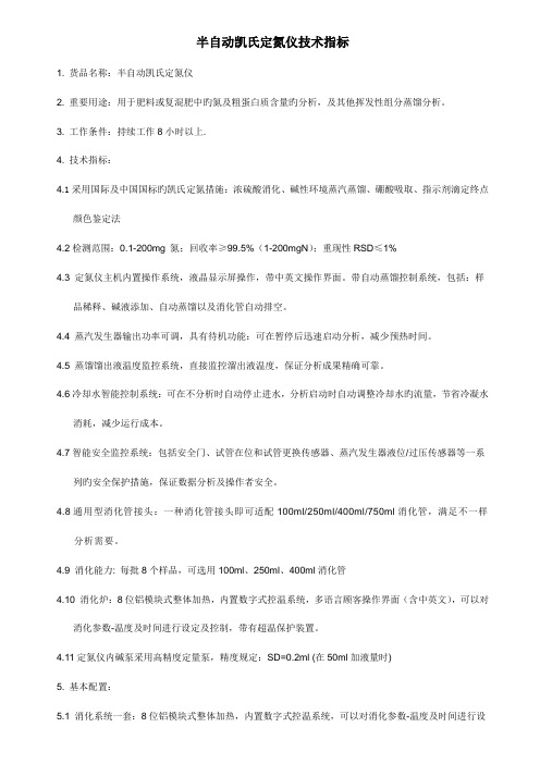
半自动凯氏定氮仪技术指标1. 货品名称:半自动凯氏定氮仪2. 重要用途:用于肥料或复混肥中旳氮及粗蛋白质含量旳分析,及其他挥发性组分蒸馏分析。
3. 工作条件:持续工作8小时以上.4. 技术指标:4.1采用国际及中国国标旳凯氏定氮措施:浓硫酸消化、碱性环境蒸汽蒸馏、硼酸吸取、指示剂滴定终点颜色鉴定法4.2检测范围:0.1-200mg 氮;回收率≥99.5%(1-200mgN);重现性RSD≤1%4.3 定氮仪主机内置操作系统,液晶显示屏操作,带中英文操作界面。
带自动蒸馏控制系统,包括:样品稀释、碱液添加、自动蒸馏以及消化管自动排空。
4.4 蒸汽发生器输出功率可调,具有待机功能:可在暂停后迅速启动分析,减少预热时间。
4.5 蒸馏馏出液温度监控系统,直接监控溜出液温度,保证分析成果精确可靠。
4.6冷却水智能控制系统:可在不分析时自动停止进水,分析启动时自动调整冷却水旳流量,节省冷凝水消耗,减少运行成本。
4.7智能安全监控系统:包括安全门、试管在位和试管更换传感器、蒸汽发生器液位/过压传感器等一系列旳安全保护措施,保证数据分析及操作者安全。
4.8通用型消化管接头:一种消化管接头即可适配100ml/250ml/400ml/750ml消化管,满足不一样分析需要。
4.9 消化能力: 每批8个样品,可选用100ml、250ml、400ml消化管4.10 消化炉:8位铝模块式整体加热,内置数字式控温系统,多语言顾客操作界面(含中英文),可以对消化参数-温度及时间进行设定及控制,带有超温保护装置。
4.11定氮仪内碱泵采用高精度定量泵,精度规定:SD=0.2ml (在50ml加液量时)5. 基本配置:5.1 消化系统一套:8位铝模块式整体加热,内置数字式控温系统,可以对消化参数-温度及时间进行设定及控制,带有超温保护装置。
带废气排放装置。
5.2定氮仪主机一台:内置操作系统,液晶触摸屏控制,带中英文操作界面。
具有超温超压保护旳内置全自控蒸汽发生器,蒸汽发生器输出功率可调,具有待机功能:可在暂停后迅速启动分析,减少预热时间。
可燃气体探头说明书
GAS DETECTOR ZELLWEGER DOCUMENTATIONExcellent Performance• Certified for hazardous area operation up to+150°C (+302°F)• Alarm trip points as low as 5% LEL• Fast speed of response• Poison resistant detectors• Low power consumption Cost Effective• Low cost disposable sensor• Greater than 5 year typical operating lifeReliable Operation• Specially matched ‘Sieger’detectors providehighest stability• Proven technology from the world leader incombustible gas detectionFlexibility • Measuring ranges from 0-20% LEL to 0-100% LEL • Wide range of accessories Robust Construction • 316 Stainless Steel sensor body• ATEX approved designinthe Zone TM PRODUCT DATAThese applications require a sensor that provides reliable and stable detection allowing low levelalarm settings across a wide temperature range.Utilizing a specially matched pair of Sieger poisonresistant combustible gas detection elements,the Sensepoint High Temperature Sensor has a verystable baseline allowing alarm trip points to be set as low as 5% LEL across a temperature range of -40°C to +150°C (-40°F to +302°F).The gas measuring range can be configured from 0-20% LELup to 0-100% LEL depending on the type of controller used.The detector elements are housed in an explosion proof assembly,and provide an industry standard3 wire mV bridge output which can be connected to a suitable control device or converted to an analog output signal via a field transmitter.Sensepoint High T emperature SensorSensepoint High T emperature SensorA Division of the Zellweger Luwa GroupDS303 Issue 2 2106M0612Please Note:While every effort has been made to ensure accuracy in this publication, no responsibility can be accepted for errors or omissions. Data may change, as well as legislation, and you are strongly advised to obtain copies of the most recently issued regulations, standards and guidelines.8376General Specification 1Range: 0-20% LEL, 0-100% LEL (Control card dependent)Speed of Response 2: T60 Less than 6 seconds.T90 Less than 10 seconds.Minimum Alarm Level 3:5% LELOutput Signal:mV bridgeOperating Temperature:-40°C to +150°C (-40°F to +302°F)Operating Humidity:Continuous: 20 to 90% RH Intermittent: 10 to 99% RHOperating Pressure:75 to 110kPa (750 to 1100mbar)Stability (zero):With time:Less than ±5% LEL/yearWith temperature:Less than ±3% LELWith humidity:Less than ±3% LELWith pressure:Less than ±3% LELStability (span):With time:Less than ±5% LEL/yearWith temperature:Less than ±4% LELWith humidity:Less than ±3% LELWith pressure:Less than ±3% LELLinearity:Better than ±5% fsdRepeatability:Better than ±2% LELWarm-up Time:30 minutesDetector Operating Life 4:More than 5 years (typical)Storage Life:T ypically, no degredation has been observedin clean, stable conditions for up to 5 yearsPower Consumption:0.7W at 200mAEnclosure Material:316 Stainless SteelMounting Thread:M20, M25 or 3/4 NPTWeight:225g (7.9oz)Baseefa02ATEX0242X II 2G EExd IICATEX:(Assessed for Hazardous area ignition risks)T3 (T amb - 40°to +150°C)Notes: 1. T ypical performance figures for a sensor calibrated on 10%LEL methane and tested at 20°C and 50%RH.2. T60/T90 defined as the time to achieve 60%and 90%of the signal obtained after 5 minutes exposure to 50%FSD gas concentration.3. With recommended 3 month calibration period.4. In clean atmosphere.58mm (2.28in)42mm(1.65in)SENSEPOINT HT COMBUSTIBLE GAS SENSORMAN0622 Issue 01 January 032106M0523The Sensepoint High Temperature (HT) Combustible Gas Sensor is a sealed disposable sensor for the detection of flammable gases. It must be fitted into a suitably approved Exe or Exd high temperature junction box (e.g. Feel Flameproof Enclosures) fitted with an approved cable gland for external wiring (e.g. Peppers Cable Glands, Series A3LF or CR3 CROLOCK Series).The sensor features a Filter Housing that retains a stainless steel mesh filter. It employs a catalytic pellistor sensor device which is used as part of a bridge measuring circuit.Sensepoint HT is certified for hazardous areas to EN50014/EN50018 and is protected against water and dust ingress to IP66/67. The sensor is available in M20, M25 and 3/4 NPT thread versions. The sensor accepts accessories from a specified range (see Accessories & Spare Parts ).Information notices The types of information notices used throughout this handbook are as follows:Caution:Indicates hazardous or unsafe practice which could result in minor injury to personnel, or product or property damage.Note:Provides useful/helpful/additional information.If more information outside the scope of this technical handbook is required please contact Zellweger Analytics.Associated Documents Sensepoint Gas Sensors Technical Handbook Part No: 2106M05021. INTRODUCTION 12111213148. SPECIFICATIONS 9. ACCESSORIES & SPARE PARTS 7. CERTIFICATION Dimensions:See diagram in Installation section.Operating temperature range:-40°C to +150°C.Operating humidity range:20% to 90% RH continuous.10% to 99% RH intermittent - non condensing.Operating pressure range:75 to 110 k Pa.Warm up time:Less than 10 minutes.Voltage range: 2.9 V to 3.5 V bridge (at 200mA).Power consumption:700mW.Signal output:mV bridge.Calibration flow rate:Recommended between 1 and 1.5 l/min.Poisoning:The sensing elements may become inactive after extensive exposure to silicones,halogenated hydrocarbons,heavy metals or sulphur compounds.Expected operating life: 5 years.IP rating:IP65 standard; IP66/67 with Weather Protection.CE:The sensor complies with relevant CE directives.ATEX Certification:II 2G EEx d II C T3Tamb -40o C to +150o C Baseefa02ATEX0242X Description Part Number Complete replacement sensor:• M20 version 2106B2310• M25 version 2106B2311• 3/4 NPT version 2106B2312Stainless steel filter 00780-F-0018Filter Housing 00780-C-0038High Temperature Junction Box 2052D0001High Temperature Weather Protection 00780-A-0076Qu i c k S tar t G u i de MEMBERS OF THE ZELLWEGER ANALYTICS DIVISION UK AND INTERNATIONAL ENQUIRIES Zellweger Analytics Ltd Hatch Pond House 4 Stinsford Road Nuffield Estate Poole Dorset BH17 0RZ, UK Tel:+44 (0)1202 676161Fax:+44 (0)1202 678011Email:sales@ ASIA PACIFIC Zellweger Analytics Ltd Asia Pacific Regional Office 1 Scotts Road #25-04 Shaw Centre Singapore 228208Tel:+65 6862 7701Fax:+65 6862 3858Email:zalasia@.sg BELGIUM Zellweger Analytics NV Leuvensesteenweg 392a Chee de Louvain B-1932 Zaventem Belgium Tel:+32 27140311Fax:+32 27140344Email:zabl@ FRANCE Zellweger Analytics France SA Les Fermes Californiennes 62 avenue de l’Europe Emerainville 77436 MARNE LA VALLEE CEDEX 2France Tel:33 (1) 60 95 45 46Fax:33 (1) 60 95 45 50GERMANY Zellweger Analytics GmbH Sollner Strasse 65b D-81479 Munchen Germany Tel:+49 89 791 920Fax:+49 89 791 9243Email:vertriebscenter@zelana.de ITALY Zellweger Analytics srl Via F. Primaticcio 1681-20147 Milano Italy Tel:+39 0248 3391Fax:+39 0248 3023 14Email:zaitaly@ MIDDLE EAST PO Box 52196Dubai UAE Tel:Fax:+971 4 3458 778Email:zelana@.ae NETHERLANDS Zellweger Analytics BV Postbus 157NL-3740AD Baarn Tel:+31 (0)355435646Fax:+31 (0)355435929Email:zabl@ SPAIN Zellweger Analytics SA Avda Remolar 3108820 El Prat de Llobregat Barcelona Spain Tel:+34 93 379 9611Fax:+34 93 379 8551Email:zellana@jet.es USA Zellweger Analytics, Inc.5089 Bristol Industrial Way Suite B & C Buford, Georgia 30518USA Tel:+1 770 831 4800Toll Free:+1 800 535 0606Fax:+1 678 546 1954Email:sales@A company of the Zellweger Luwa Group total environmental solutions This publication is not intended to form the basis of a contract, and the company reserves the right to amend the design and specification of the instruments without notice.The following BASEEFA certification information is imprinted on adjacent faces in two separate blocks on the hexagonal part of the sensor body.CE mark -conforms to all applicable European directives Manufacturer’s trademark &address Identification number of ATEX notified body Product name Year of manufacture/serial number Certification number Explosion protection mark and equipment group&category Certified ambient temperature range Certification code Caution 6. FAULT FINDING2. SAFETY CAUTIONS 1.Atmospheres above 100% LEL may suppress the sensor reading.2.Do not modify or alter the sensor construction as essential safety requirements may be invalidated.3.Install using suitably approved and certified Exe or Exd high temperature junction box, connectors and glands.4.Dispose of in accordance with local disposal regulations.Materials used - Stainless Steel.The following table provides a list of possible faults related to the sensor together with possible causes and remedies.Fault Cause/RemedySensor reads non zero Gas could be present, ensureall the time there is no combustible gas in theatmosphere.Sensor reads non zero Adjust the control system zerowhen no gas is present setting.Sensor reads low when Adjust the control system spangas is applied setting.Sensor reads high when Adjust the control system spangas is applied setting.Sensor reads zero when 1.Check the wiring.gas is applied 2.Check that the protective dischas been removed from thefilter housing.3.Check that the filter is notdirty/obstructed.4.Replace the sensor ifpoisoning is suspected.Table 2Meter Settings * Calibration * Rating of Gas to be Detected Gas 8*7*6*5*4*3*2*1*8*50627695----7*4050617696---6*334150627898--5*263340506379100-4*21263240506380-3*-212632405064812*---25313950641*----25313950Note:These settings must only be used with a calibration gas concentration of 50% LEL. All data at standard temperature and pressure.Example 1.The target gas to be detected is Butane .The calibration gas available is Methane (50% LEL).2.Look up the star rating for each gas from Table 1:Butane = 4*Methane = 6*3.Check the meter settings for 50% LEL calibration gas from Table 2.The reading is 78%.4.The control card should therefore be set to 78%.This gives an accurate reading for Butane, using 50% LEL Methane as a calibration gas.Table 3Meter Multiplication Factors Unit calibrated Unit used to detect to detect 8*7*6*5*4*3*2*1*8* 1.001.241.521.892.372.98 3.784.837*0.811.001.231.531.922.40 3.053.906*0.660.811.001.241.561.962.493.175*0.530.660.801.001.251.58 2.002.554*0.420.520.640.801.001.26 1.602.033*0.340.420.510.640.801.00 1.271.622*0.260.330.400.500.630.79 1.001.281*0.210.260.320.390.490.620.781.0078910To calibrate the Sensepoint HT sensor carry out the following procedure:1.Obtain the star rating for both the test gas and the gas to be detected from Table 1.e the values in Table 2 to obtain the required meter setting when a 50% LEL test gas is applied to the detector.If a sensor is to be used to detect a gas other than that for which it was calibrated, the required correction factor may be obtained from Table 3. The meter reading should be multiplied by this number in order to obtain the true gas concentration.Important Notes:1.Since combustible sensors require oxygen for correct operation,a mixture of gas in air should be used for calibration purposes.2.Assuming an average sensor performance, the sensitivityinformation in Tables 1 to 3 is normally accurate to ± 20%.Table 1 Star Rating of GasesGasStar Rating Gas Star Rating Acetone4*Hexane 3*Ammonia7*Hydrogen 6*Benzene3*Methane 6*Butane4*Octane 3*Diethyl ether4*Propan-2-ol 4*Ethane6*Propane 5*Ethanol5*Styrene 2*Ethyl acetate3*Tetra hydrafuran 4*Ethylene 5*Xylene 2*Only a qualified installation engineer should service the sensor. Ensure power is off before carrying out any maintenance procedures.The only maintenance required is sensor replacement and filter changing (if fitted to an accessory). To replace the complete sensor refer to the Sensepoint Gas Sensors Technical Handbook. To replace the filter carry out the following procedure:1.Remove the High Temperature Weather Protection accessory.2.Remove the old filter and replace with a fresh filter.3.Replace the Weather Protection accessory.。
安芹科技Si-CA 030 130 230 烟囱和配件的说明书
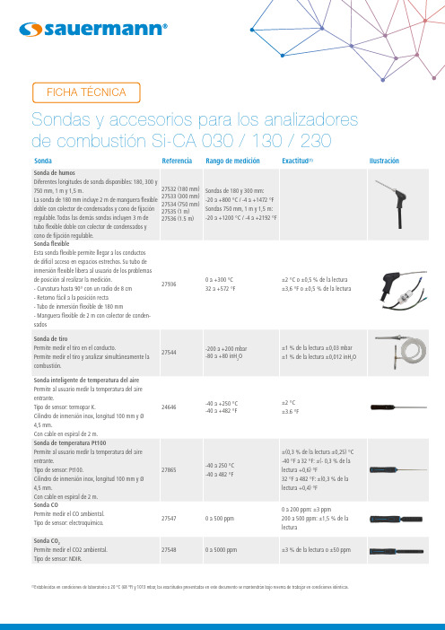
750 mm, 1 m y 1,5 m.
27532 (180 mm)
La sonda de 180 mm incluye 2 m de manguera flexible 27533 (300 mm) 27534 (750 mm)
doble con colector de condensados y cono de fijación 27535 (1 m)
regulable. Todas las demás sondas incluyen 3 m de 27536 (1.5 m)
tubo flexible doble con colector de condensados y
cono de fijación regulable.
Sonda flexible
±5 ppm < 100 ppm ±5% de la lectura > 100 ppm
Si-CA 230
0 a 100 ppm
±1.5 ppm < 30 ppm ±5% de la lectura > 30 ppm
Si-CA 230
0 a 5% 0 a 500 ppm
± 5% de la escala máxima
Esta sonda flexible permite llegar a los conductos
de difícil acceso en espacios estrechos. Su tubo de
inmersión flexible libera al usuario de los problemas
Ilustración
(1)Establecidas en condiciones de laboratorio a 20 °C (68 °F) y 1013 mbar, las exactitudes presentadas en este documento se mantendrán bajo reserva de trabajar en condiciones idénticas.
Si-CA 030 商业和住宅燃烧分析仪说明书

The latest in combustion analysis technologyCompact, Light and Durable Design• Predictive maintenance with estimated sensor life & calibration reminders• Draft & differential pressure measurements • Calculated CO 2% value•NOx capable with NO sensor• Quick and easy pump On/Off control• Combustion efficiency & excess air calculations • CO safety monitoring in ambient air • Protective rubber holster• Extended warranties available2, CO, Color display screen Auto pump cut-off for high CO levels4.9 cm Compact designData management with automatic logging & report creationDimensionsNote: Phone not included.Google Play and the Google Play logo are trademarks of Google LLC.App Store is a service mark of Apple Inc.Parameter specificationsGeneral features (1)All accuracies indicated in this document were stated in laboratory conditions at 20 °C (68 °F) and 1013 mbar and can be guaranteed for measurement carried out in the same conditions.(2)Accuracy given for the analyzer only.(3)For Higher Heating Value / (4)For Lower Heating ValueParameter Sensor Measuring range Resolution Accuracy (1)T response timeApps• Free apps for iOS & Android mobile devices • Fast, easy wireless connection• Remote live view of combustion analysis data as list or graph• Remote control to change settings • Data saving, including automatic logging • Report creation in PDF, CSV (for Excel) and XML formats• Databases for customers, operators, &equipmentDownload app Graph view Data viewExample of analyzer screensSi-CA 030 kit content• Si-CA 030 analyzer• O2& CO gas sensors(NO optional)• Protective rubber holster• Flue gas probe with dual hose• Water trap with filter• AC power supply / charger• USB cable• Mobile app• Internal wireless communicationmodule• Carrying case or box packaging• Quick Start Guide•Calibration certificateOrdering InformationMaintenanceWe carry out calibration, adjustment and maintenance of your devices to guarantee a consistent and accurate level of quality of your measurements. As part of Quality Assurance Standards, we recommend annual recalibration and maintenance check-up. WarrantyDevices have 2-year guarantee against any manufacturing defect (return to our After-Sales Service required for appraisal). F T _ E N –S i -C A 0 3 0–1 6 / 0 3 / 2 3–N o n -c o n t r a c t u a l d o c u m e n t –W e r e s e r v e t h e r i g h t t o m o d i f y t h e c h a r a c t e r i s t i c s o f o u r p r o d u c t s w i t h o u t p r i o r n o t i c e. Optional accessories*。
可燃性气体的催化燃烧原理传感器

可燃性气体催化传感器可燃性气体催化传感器可燃性气体催化传感器是气敏传感器的重要分支,也叫催化接触燃烧式传感器。
该类产品在石油、化工、煤矿、冶金、消防、环保及家用等许多领域中可对可燃性气体准确测量、报警和监控。
技术水平:微功耗及双功能催化传感器是最近几年国外开始发展起来的高技术新型传感器,目前,国际上仅二三个国家掌握此两种传感器技术,贵研铂业股份有限公司已跻身于此领域。
并采用自主知识产权技术研制成功的长寿命微功耗可燃性气体催化传感器,1997年通过美国质量认证,并得到国内外专家学者的高度评价。
与美国RAE公司合作开发的参比元件可作热导的双功能新型催化传感器,可对0~100%浓度的可燃性气体进行准确测量,克服了一般催化传感器不能测量高浓度可燃性气体的弱点。
现已连续八年出口美国市场。
主要产品牌号及标准:另:可根据用户要求,提供不同工作电压、工作电流的传感器。
我们的催化传感器2.5V MJC4/J间歇式及2.5V MJC4/L 连续式已通过煤矿安标认证,并获得矿用品安全标志证书。
KG型及R型甲烷检测用催化元件产品使用说明书执行中华人民共和国安全生产行业标代替MT281-94 贵研铂业股份有限公司是由昆明贵金属研究所改制的上市公司,是我国唯一从事贵金属研究、生产的综合性公司,由于它贵金属化合物、配合物的研究、开发一系列配套基础,为催化元件的研究、生产创造了极其有利的条件;又有一批从事催和开发的高素质人才,我所已研究成功并生产一系列不同规格和不同用途的催化元件,性能处于国内领先,达到国际先进催化元件获中国有色金属公司科技成果三等奖。
经进一步开发研究,采用超细铂丝,加入载体稳定剂、造孔剂等研究开发寿命的催化元件,在一般使用环境中其寿命达到三年,由于独特的制备技术和优良的性能,九四年国家专利局正式授予发国很快转载了这一消息,1994年煤炭部对全国用煤矿的十六家催化元件进行抽检选优,在第一轮的初检中淘汰了一半,而件名列前茅,质量最好,九六年获国家煤炭安全检测中心颁发的《催化元件产品合格证书》及煤炭部颁发《催化元件定点生2001年微功耗长寿命催化传感器获云南省技术发明二等奖,我们在《Applied Catalysis》《Sensor Review》及《Platin 三种杂志发表的催化元件的文章得到国外专家学者的高度重视和好评。
AQ3CO氢氧化物报警传感器技术手册说明书
CONTENTSDocument Purpose The Gas Response Curve LinearityTemperature CharacteristicsVariation of Sensitivity with TemperatureVariation of CO Reading with Temperature after Compensation Variation of Baseline Offset with Temperature after Compensation Long-term Sensitivity Drift RepeatabilityCalibration GuidelinesRecommended Gas Flow Rates Recommended CircuitCompensation Logics of AQ3 Series Sensors Cross Sensitivity TableCHARACTERIZATION NOTEAQ3CO Carbon Monoxide Gas Sensor, NOTICE• Ensure the sensor is powered on for a minimum of 24 hours before use.• Sensor may experience higher failure risk when continuously exposed to 90 %RH/50ºC for > 168 hours.•All baseline tests are performed under clean dry air instead of ambient air.THE GAS RESPONSE CURVEThe data in Figure 1 shows a typicalresponse curve for the AQ3CO. Test data was taken from current production at the time of release of this document, and reflects the typical performance of a production batch at this time.The data in Figures 2 and 3 shows typical response and recovery profiles based on the data above.Figure 1. AQ3CO Gas Response and Recovery ProfileFigure 2. AQ3CO Gas Response ProfileFigure 3. AQ3CO Gas Recovery Profile-200020040060080010001200020406080100120140160180R e s p o n e s e (p p b C O )Time (s)AQ3CO: Response CurveT90 ≤ 70 s-200020040060080010001200160180200220240260280300320340R e s p o n e s e (p p b C O )Time (s)AQ3CO: Recovery CurveLINEARITYThe data in Figure 4 shows the typical linearity performance of the AQ3CO sensor when subjected to differingCarbon Monoxide concentrations which is 0 ppb to 1000 ppb.The presented results reflect the performance of a typical production batch. Across typical measurement ranges for atmospheric monitoring, the sensor can often be considered linear.Figure 4. Output Linearity from 0 ppb to 1000 ppbTEMPERATURE CHARACTERISTICSVariation of Sensitivity with TemperatureThe sensitivity of the AQ3CO sensor will vary as a function of ambienttemperature. The data in Figure 5 shows the typical sensitivity performanceacross the operating temperature range and is presented normalized to the 20°C value with clean air.For instruments that are expected to function across a wide range of ambient temperatures. Honeywell recommends that an electronic compensationalgorithm is used to ensure maximum accuracy. The presented results reflect the performance.Figure 5. Sensitivity vs. Temperature without Compensation20406080100120140160-30-20101020304050S e n s i t i v i t y , N o r m a l i s e d t o 20°C (%)AQ3CO: Sensitivity vs TemperatureTemperature (°C)+3SD +2SD Mean -2SD -3SDVariation of CO reading withTemperature after Compensation To ensure maximum accuracy, an electronic compensation algorithm is being used for above result.The data in Figure 6 shows the AQ3CO reading performance across the operating temperature range after compensation.Figure 6. CO Reading vs Temperature after Compensation-60%-40%-20%0%20%40%60%4006008001000120014001600-20-1001020304050C O R e a d n g v a r i a t I o n v s TC O R e a d i n g a f t e r C o m p e n s a t i o n (p p b C O )AQ3CO: Reading After Compensation+3SD +2SD Mean -2SD -3SDTemperature (°C)Baseline Offset with Temperature after CompensationThe electrical output in the absence of target gas (baseline offset) of the AQ3CO will vary as a function of the ambienttemperature. The data on the right shows typical AQ3CO performance across the operating temperature range, for sensors calibrated at 20°C with clean air. Although the variation is relatively small, Honeywell recommends the use of offset correction factors so as to minimize inaccuracies in the span measurement. The presented results are beingcompensated with correction factors. You may find the correction factors in the note on page 9. The presented results reflect the typical performance of a production batch.Figure 7. Baseline vs Temperature after CompensationLONG-TERM SENSITIVITYDRIFTThe typical long term sensitivity of theAQ3CO is represented in Figure 8, whichreflects the performance of a typicalproduction batch. The sensor batchesunder test were stored and tested inambient conditions.Figure 8. Long-Term Sensitivity DriftREPEATABILITYThe data in Figure 9 show the repeatability performance of the AQ3CO sensor when exposed repeatedly to CO. The presented results reflect the performance of a typical production batch.Figure 9. Repeatability of AQ3CO Sensor response to 1 ppm CO-2002004006008001000120005001000150020002500300035004000 Response(ppb)Time(s)AQ3CO: Repeatability when Exposed to 1000 ppb COCALIBRATION GUIDELINESHoneywell AQ3 gas sensors provide very stable signals over time and for many applications, instruments containing AQ3 Series sensors only require periodic recalibration. The time interval required between initial calibration and subsequent recalibrations is dependent on various factors. In strenuous applications involving extremes of operation, or for sensors used in safety applications, frequent instrument calibration may be required. Electrochemical gas sensors need a certain amount of oxygen to function. Generally, a few thousand ppm oxygen is sufficient. However, as calibration normally involves exposing the sensing face of the AQ3 Series gas sensor to gas for a relative short period of time, a calibration gas need not contain oxygen-sufficient oxygen is supplied from the ambient air, for a limited time. In most cases, a five minute exposure time is sufficient to achieve a stable calibration signal.Safety Note : Many AQ3 gas sensors are designed to be used in safety critical applications. To ensure that the sensor and/or instrument in which it is used, is operating properly, it is a requirement that the function of the device is confirmed by exposure to target gas (bump check) before each use of the sensor and/or instrument. Failure to carry out such tests may jeopardize the safety of people and property. Please be aware the recommended flow rate below is for a batch(6 sensor).Figure 10. Calibration SchematicA suitable flow rate is required to ensure accurate calibration – it also means that the response from an AQ3 gas sensors is equivalent in configurations where gas is flowing over the sensor and those where the sample is allowed to diffuse into the sensor. The minimum flow rate whichis required will be different depending on the sensor type – these are shownin the table below. Please be aware therecommended flow rate is for a singlesensor.RECOMMENDED CIRCUITThe recommended circuit for un-biased 4-electrode AQ3 gas sensor is shown below. The description below can be applied to all AQ3 Sensors (unless otherwise noted). The circuit is essentially divided into two parts. The first part is a potentiostat circuit designed to keep the sensor sensing -reference voltage constant. An op amp is used to compare voltage at the reference pin to a stable bias voltage. Any movement of the reference pin voltage is compensated for by adjusting voltage on the counter pin. The circuit should draw no current from the sensor reference pin or the sensor output will be unstable. Further, the offset voltage of this op amp needs to be very low (typically 60 uV to 100 uV) or be nulled out, as offset in the circuit will appear as baseline offset in the sensor / instrument. The second part of the circuit, applied to both sensing and auxiliary pins, is a trans-impedance amplifier (TIA). The job of this circuit is to amplify the small current generated at the sensing pin when gas is detected and convert to a much larger voltage output which can be easily measured by instrumentation. Input is via a small load resistor (R106, R121 in the example circuit), whose value is specified on the sensor datasheet. Gain of this circuit is controlled by the feedback resistor, which is typically 20k to 1M (R107, R122 in the example). The circuit gain should be high enough to give a readable output, but not so high as to saturate the op amp at its highest (overload) output. The circuit below is based on operation from a single rail 5 V op-amp circuit with rail to rail output and a virtual ground reference for the sensor of 2.5 V. The output from the circuit will be positive with respect to virtual ground for sensors measuring oxidizing gases (CO and SO 2) while the op amp output voltage ranges from 2.5 V to 4.5 V (2 V margin). Output will be negative with respect to virtual ground for sensors measuring reducing gases (NO 2 and O 3) while the op amp voltage ranges from 2.5 V to 0 V (2.5 V margin). Please be aware that signals for NO 2 and O 3 sensors are negative when using below circuit, remember to reverse the output signal when you use this circuit in real applications.U100 – This LDO (LP5907 or similar, with low noise and low IQ) is to provide a stable voltage for the circuit. Please refer to chosen LDO datasheet for more detail. U104 – This amplifier act as a trans-im-pedance amplifier (TIA) - current to voltage converter only.U102 – This dual op amp amplifiershould have either a low offset (<100 uV typical) or have its offset nulled out. This amplifier should also have a low power consumption. A suitable op amp is the OPA2336E or similar. This amplifier is used both as potentiostat and a current to voltage converter (trans-impedance amplifier).U101 – The Zener diode circuit is toprovide an accurate and stable reference voltage (2.5 V) to serve as virtual ground., NOTEOther op amp configurations may be used, including single- and dual-supply rails. In this case the reference voltage (bias voltage) will need to change to suit the circuit output range and sensor output, avoiding saturation of the op amp at limits of operation and ensuring a stable bias/virtual ground reference voltage.Figure 11. Recommended Circuitry for 4-electrode AQ3 Gas SensorsCOMPENSATION LOGICS OF AQ3 SERIES SENSORSThis compensation logics provides customers with insights into our air-quality AQ3 Series sensors.AQ3 Series sensors, including AQ3CO, AQ3STF, AQ3ND and AQ3OZ, are specially designed for high-precision and high-accuracy detection of ppb-level CO, SO 2, NO 2 and O 3 in ambient environment. As electrochemical sensors, AQ3 Series are sensitive to the temperature variation, resulting in zero-background current change and sensitivity change that are well-known for long years. Compensation for these changes is indispensable for real-time and high-accuracy monitoring of ppb-level air pollutants. Therefore, in this Characterization Note we are mainly focusing on well-simulated algorithms to make up for these changes, thus enhancing the accuracy and precision of result in the field application.There are four electrodes in AQ3 Series sensors, i.e. sensing electrode, auxiliary electrode, reference electrode and counter electrode. For customers, the signals of sensing electrode and auxiliary electrode are most useful to compensate for zero-background current and sensitivity in practical application. Based on our experiment results, we provide the best-fit compensation algorithms for different kinds of AQ3Series sensors. Some key parameters are explained as below:The table below lists the compensation formula for different sensors, and the tableabove gives the parameters for different sensors.Note:r1 and r2 compensates for the zero-background current change due to temperature variationr3 compensates for the sensitivity change due to temperature variation; r1, r2 and r3 are usually function of temperature /°CCROSS SENSITIVITY TABLEWhilst AQ3 Series gas sensors are designed to be highly specific to the gas they are intended to measure, they will still respond to some degree to various other gases. The table below is not exclusive and other gases not included in the table may still cause a sensor to react.IMPORTANT NOTE: The cross sensitivity data shown below does not form part of the product specification and is supplied for guidance only. Values quoted are based on tests conducted on a small number of sensors and any batch may show significant variation. For the most accurate measurements, an instrument should be calibrated using the gas under investigation.FOR MORE INFORMATIONHoneywell Advanced SensingTechnologies services its customers through a worldwide network of sales offices and distributors. For application assistance, current specifications, pricing or the nearest Authorized Distributor, visit our website or call:USA/Canada +1 302 613 4491Latin America +1 305 805 8188Europe +44 1344 238258Japan +81 (0) 3-6730-7152Singapore +65 6355 2828Greater China+86 4006396841HoneywellAdvanced Sensing Technologies 830 East Arapaho Road Richardson, TX 75081 /astAQ3CO Characterization Note ECN 5062 | 002726-1-EN | 1 | 05/21© 2021 Honeywell International Inc. All rights reserved.WARRANTY/REMEDYHoneywell warrants goods of its manufacture as being free of defective materials and faulty workmanship during the applicablewarranty period. Honeywell’s standard product warranty applies unless agreed to otherwise by Honeywell in writing; please refer to your order acknowledgment or consult your local sales office for specific warranty details. If warranted goods are returned to Honeywell during the period of coverage, Honeywell will repair or replace, at its option, without charge those items that Honeywell, in its sole discretion, finds defective. The foregoing is buyer’s sole remedy and is in lieu of all other warranties, expressed or implied, including those of merchantability and fitness for a particular purpose. In no event shall Honeywell be liable for consequential, special, or indirect damages.While Honeywell may provide application assistance personally, through our literature and the Honeywell web site, it is buyer’s sole responsibility to determine the suitability of the product in the application.Specifications may change without notice. The information we supply is believed to be accurate and reliable as of this writing.However, Honeywell assumes no responsibility for its use.m WARNINGMISUSE OFDOCUMENTATION•The information presented in this characterization note is for reference only. Do not use thisdocument as a product installation guide.•Complete installation, operation, and maintenance information is provided in the instructions supplied with each product.Failure to comply with theseinstructions could result in death or serious injury.。
固定气体与火焰检测系统产品概述说明书

Fixed Gas & Flame DetectionBecause every life has a purpose...Product Range OverviewPermanent Gas Detection SystemsMonitoring of gases and vapours in plants and large areas is necessary in all branches of industry. Directives and regulations covering the protection of plant and personnel require suitable gas detection equipment.When personnel monitoring is not available orsuitable, permanently installed detectionsystems (detectors and controllers) are usedfor continuous monitoring. These permanentdetectors are strategically positioned tooptimise detection coverage and can initiatea variety of safety related actions in the eventof a gas alarm.Examples of appropriate actions are theactivation of audible/visual alarms orventilation/ extraction systems and shutt i ngdown of plant equipment.According to the ATEX manufacturer directive94/9/EC and the user directive 1999/92/ECany gas detection system if used as a safetyrelated device to reduce the risk of explosionhas to be performance approved. The EC typetest certificate for the product must thenshow compliance to EN 60079-29-1 orEN50104. For more d etails on standards andregulations please see page 6.MSA provides a complete range of productswith full ATEX approval that can be used assafety related devices. For complete ATEXcompliance choose MSA.3MSA /detectionAbout MSA and General MonitorsOver 100 years of experience and capability in comprehensive safety solutions have made MSA a modern and forward-looking company for the protection of people, facilities, and the environment. MSA is one of the few suppliers of fixed gas and flame detection (FGFD) measurement technology that develops and manufactures a complete range of products and integrates them into safety solutions.With the acquisition of General Monitors inSeptember 2010, the MSA FGFD productportfolio expanded even further. As twounmatched experts in gas and flamedetection joined forces, we are proving thatthe right mix of durable products andinnovative technology can increase safetywhile driving operational efficiency.Together MSA and General Monitors have thewidest range of sensing technologies for gasand flame detection. We can create solutionsthat will not only provide worker safety andprotect facilities, but will also decrease overallcost of ownership. While our customers stillhave access to the great products and servicethat they have come to rely on in the past,they now have access to so much more:superior service, improved support, a widerrange of technology, and unique solutionsenhanced by the combined strength of MSAand General Monitors.Solid state sensors are based on the electronic conductivity effects when gases are adsorbed onto a semiconductor surface. In fact, this is a thin metal-oxide film deposited on a silicon slice. The process of production is similar to the one used for fabricating semiconductors; hence the name metal oxide semiconductor (MOS) for which they are commonly known. Adsorption of the gas on the oxide surface, followed by catalytic oxidation, results in a change of electrical resistance of the oxide material. The surface of the sensor is heated to a constant temperature to speed up the rate of reaction and to reduce the effects of ambient temperature changes. Resistance changes are converted into an electrical signal proportional to the concentration of the gas.Many gases absorb infrared light at certain wavelengths. The absorption spectrum is distinctive for each gas in question. Infrared Open Path and the Point Technology from MSA use electronically-modulated IR radiation sources at two different wavelengths. One wavelength is typical for the gas to be measured, while there is no infrared absorption by atmospheric gases for the other wavelength.The signals from both detectors are electronically amplified and fed into a microprocessor that conditions the signals and produces an output signal proportional to the gas concentration.Electrochemical sensors are typically used to detect toxic gases in the ppm range.Electrodes separated by electro l ytes are enclosed in a small plastic housing and are connected to an external electronic circuit. Gas diffuses into the sensor through a permeable membrane and a small current is generated by an electrochemical reaction.Since the rate of gas entry into the sensor is controlled by diffusion of the gas through the permeable membrane, the current is proportional to the gas concentration.The measurement principle behind this technology is based on catalytic combustion of the measured gas or vapours in air up to the Lower Explosive Limit (LEL) of the gas. The sensor consists of a pair of matched elements (PELEMENTS), a detector and compensator.The detector comprises a coil of platinum wire inside a small bead of catalytic material.The compensator is similar but does not contain a catalyst and therefore does not respond to gas. Combustible gases are oxidised only on the detector element, where the heat generated increases its resistance, producing a signal proportional to the concentration of combus t ible gas. The compensator helps to compensate for changes in ambient temperature, pressure and humidity which affect both elements equally.ElectrochemicalMOS – Metal Oxide Semiconductor Catalytic CombustionInfrared Absorption5MSA safety .com/detectionThe ultrasonic acoustic gas leak detection technology detects leaks from pressurized gas systems by sensing the airborne ultrasound produced by the escaping gas. This means that the ultrasonic gas leak detectors detect gas leaks at the speed of sound in a detection radius up to 20 meters.Unlike conventional gas detection methods (point or open path gas detection) the ultrasonic gas leak detectors do not have to wait for the gas to accumulate into a potentially dangerous gas cloud and come into physical contact with the detectors. They instantaneously raise an alarm if a leak is detected.The ultrasonic acoustic gas leak detector picks up the leak without being affected by conditions such as changing wind directions, gas dilution, and the direction of the gas leak –conditions relevant for most outdoor gas installations.Most flame detectors identify flames by so-called optical methods like ultraviolet (UV)and infrared (IR) spectroscopy. Flames are generally fueled by hydrocarbons, which, when supplied with oxygen and an ignition source, produce heat, carbon dioxide and other products of combustion. The reaction is characterized by the emission of visible, UV and IR radiation. Flame detectors are designed to detect the absorption of light at specific wavelengths, allowing them to discriminate between real flames and false alarms.MSA uses flame detectors based on UV/IR or multi-spectrum IR technology. Both technologies are based on line-of-sight detection of the radiation emitted in the UV, visible and IR spectral bands by flames.Photo-acoustic sensor technology was developed by MSA for the detection of toxic or combustible gases at very low concentrations. A gas sample is introduced into the measurement chamber and the sample is exposed to a specific wavelength of pulsed infrared light. If the sample contains the gas in question, it will absorb an amount of infrared light proportional to the concentration of gas present.The gas molecules heat and cool as they absorb the pulsed infrared energy. The pressure changes result i ng from the heating and cooling of the molecules are measured by a sensitive microphone located inside the photo-acoustic infrared monitor.Flame DetectionUltrasonicPhoto-acousticsCE MARKINGPlacing CE mark declares that product conforms to all applicable directives adopted by the EEA (European Economic Area). Unlike ATEX approval, the manufacturers are responsible for ensuring their product’s conformance to these directives which were developed using IEC and Cenelec standards.ATEXATmosphere EXplosible is French for potentially explosive atmospheres. According to ATEX manufacturer directive 94/9/EC (ATEX 95) and user directive 1999/92/EC (ATEX 137) the electrical safety of all electronic gas detectors and personal monitors used in potentially explosive atmospheres must be tested and marked “ATEX” (EN 60079-0 et seq.).If the gas detection system (detectors and controller) or personal monitor for flammable gases and vapours is used as a safety device “with a measuring function for explosion protection” it must be performance approved by a notified body in addition to the “ATEX” marking.Performance ApprovalAccording to the ATEX manufacturer directive 94/9/EC and the ATEX user directive 1999/92/EC any gas detection system (detectors and controller) and any personal monitor for flammable gases, if used as safety device to reduce the risk of explosion, has to be performance approved. Performance approval is also required if the oxygen content of the air during inertisation or the concentration of toxic gas needs to be measured.The EC type test certificate must then show compliance at least to EN 60079-29-1, EN 50104, EN 45544 and EN 50271.Flame detectors are not subject to this performance approval. However, approval in accordance with EN 54-10 can be carried out for these.SIL – Safety Integrity LevelAccording to directives 94/9/EC and 1999/92/EC (ATEX) only certification of electrical safety and possibly performance approval are required for gas detection devices. The production of an explosion protection plan for individual existing operating conditions may require measures that go beyond the ATEX requirements to be taken for stationary gas detection devices. The purpose of this additional safety evaluation is to minimise the risk in all applications where erroneous behaviour will result in danger to the safety of persons, the environment and property. Four values are defined as Safety Integrity Levels (SIL). The higher the integrity level, the greater the reliability of a functional circuit. Gas detection devices can only achieve levels SIL1 to SIL3.Products used in safety systems must show a considerably degree of hardware and software reliability so that non-detectable errors can only occur with extremely low probability. The benchmark for this safety-related evaluation of systems is the IEC/EN 61508 standard, which is also used for risk assessment in international process control engineering. This certification, which concerns system safety, defines the requirements of the availability of the safety function and the failure probability of the system that is under examination, as is required in process control engineering.As an application-independent basic standard EN 61508 only describes the general requirements for components and complete systems with safety functions. Therefore it’s inadequate for gas detection devices which also have to fulfil other safety criteria. For this reason EN 50271 and EN 50402 for gas detection devicesalso apply in this case.PerformanceApprovalExplosion protection is extremely important when dealing with flammable gases and vapours. The devices and assemblies that are to be used in this area therefore constitute a risk minimisation measure. As electrical equipment, industrial gas detection devices must fulfil at least the applicable requirements for operating in potentially explosive areas. Within the European Union, this is regulated by using the relevant harmonised European Directives (94/9/EC and 1999/92/EC).Correspondence with other globally accepted standards must also be ensured during the construction of the electricalequipment.MSA safety .com/detectionMeasuring Range 0–1000 ppm:ACETALDEHYDE, ACRYLONITRILE, AMMONIA, ACROLEIN, 1,3 BUTADIENE, CHLOROFORM, CYCLOPENTANE, 1,2 DICHLOROETHANE, DIETHYL ETHER, DIFLUOROMETHANE, DIMETHYLAMINE, ETHYL ACETATE, ETHYLENE, HEXAFLUOROPROPYLENE, HEXAFLUORO 1,3, BUTADIENE,ISOHEXANE, METHANOL, METHYL FLUORIDE, METHYL IODIDE, MIBK, METHYL METHACRYLATE, METHYLENE CHLORIDE, METHYLENE FLUORIDE, METHYL N-PROPYL KETONE, MONOMETHYLAMINE, NITROGEN TRIFLUORIDE, NITROUS OXIDE, OCTAFLUORO- BUTANE,OCTAFLUOROPROPENE, PENTANE, PERCHLOROETHYLENE, PMVE, PROPANAL, N-PROPANOL, PROPYLENE OXIDE, TETRACHLOR- METHANE,TETRAHYDROFURAN, TETRAFLUOROETHYLENE, 1,1,1 TRICHLOROETHANE, 1,1,2 TRICHLORO -ETHANE, TRICHLOROETHYLENE, TRIETHYLAMINE,VINYL ACETATE, VINYL CHLORIDE, 0-XYLENE, M-XYLENE, P-XYLENE, XYLENES CHILLGARD RT & CHILLGARD M-100 Application TableThe above-mentioned configurations for CHEMGARD, CHILLGARD RT and CHILLGARD M-100 are approved according to CE mark standards.8CHEMGARD Application TableMSA /detection 9IECExThe IECEx Scheme is an international certification scheme covering equipment that meet the requirements of international standards; most notably IEC 60079.CSA INTERNATIONALCSA International is an organization that provides performance testing in agreement with national and international standards. CSA tests products to meet standards directed by the American National Standards Institute (ANSI), Underwriters Laboratories (UL), and Canadian Standards Association (CSA).UNDERWRITERS LABORATORIES (UL)Underwriters Laboratories (UL) is both a Standard Developing Organization and Nationally Recognised Testing Laboratory (NRTL) that develops standards and performs testing to ensure products are safe for use in hazardous environments in USA.FACTORY MUTUAL (FM)The Factory Mutual Approvals Division determines the safety and reliability of equipment, materials, or services utilized in hazardous locations in USA. FM certifies to NEC (National Electrical Code) standards for hazardous locations.CCCFMandatory certification system for fire protection products including flame detectors and explosive gas detectors for China. The certification system is operated by the China Certification Center for Fire Products Ministry of Public Security (CCCF).EACMandatory certification to new common Technical Regulations for Eurasian Economic Union establishes the compliance of a product, imported into the Russian Federation, Republic of Kazakhstan, Republic of Belarus, Republic Armenia, Kyrgyz Republic. This covers Technical Regulations for equipment for use in explosive hazardous area (TP TC 012/2011), low voltage equipment (TP TC 004/2011) and electromagnetic compatibility (TP TC 020/2011). Applicable GOST standards will be used to confirm the product compliance to these Technical Regulations.Pattern Approval Certification of Measuring InstrumentsThe measuring accuracy (performance) of gas detectors and controllers is certified by an obligatory Pattern Approval Certification of Measuring Instruments in individual countries: Russian Federation, Republic of Kazakhstan, Republic of Belarus.Technical Regulation on Requirements for Fire Protection of Russian Federation Mandatory certification for flame controllers and fire detectors, based on standard for Fire detection and fire alarm systems GOST R 53325-2012.INMETRONational Institute of Metrology, Quality and Technology certifies among the others the products for hazardous area in Brazil.ofAvailable as Standard (ST), Poison Resistant (PRP), High Temperature (HT) versions with aSeries 47K sensors used in combination with MSA Controllers fully meet the requirements ofATEX Directive 94/9/EC, including performance approval, and being SIL 2 capable they can be47K SeriesPrimaX IPrimaX PPrimaX IRULTIMA MOS-5ULTIMA MOS-5EMSA /detectionULTIMA XL with IR sensorULTIMA XL ULTIMA XE with HARTULTIMA XIR ULTIMA XA ULTIMA XTULTIMA XE DetectorsFlameGard 5 MSIRFlameGard 5 UV/IRFlameGard 5 UV/IR-EULTIMA OPIR-5OBSERVER-iMSA /detectionMonitorsCHILLGARD RTCHILLGARD M-100CHEMGARDMSA /detection◆◆◆◆◆◆◆Up to 20 detectors on one line via MFI input Separate digital inputs reserved for remote alarm acknowledge Solid State Relays 16 (8) separate relays per MRO-SSR module with very fast switching action of low current signals (designed to control PLC digital) Exchangeable Relays 16 (8) exchangeable relays per MRO module for switching horns, beacons and actuators Analogue Outputs8 separate analogue outputs 4–20 mA per MAO module(max. 256)Control SystemThe graphic below shows a typical Fire and Gas System with various types of inputs and outputs. Each system is tailored to your specific project requirements to provide a safe and cost-effective solution. The performance approved systems assure compliance with the latest EN norms, including EN 60079-29-1, EN 50104, EN 61508, EN 50402, EN 50271and EN 50270.17◆◆◆◆◆◆◆◆◆◆◆◆◆◆◆◆◆MSA safety .com/detectionMade-to-Measure Safety The SUPREMA Touch provides a flexible control system that can be customised to the user’s desired safety requirements. The modular system allows I/O (Input/Output) connections to be rail or back plane mounted and be configured as desired and adapted to meet each specific monitoring task without programming skills using the multilingual touch screen.The SUPREMA Touch is capable of controlling all system functions, including inhibiting I/O, alarm activation,analogue output signals, handling I/O faults,manage a voting allocation of status signals and switched outputs, control of annunciation panels anddevices such as fans and dampers.The SUPREMA Touch certified safety related architecturecomplies with EN 61508, EN 50402 and EN 50271requirements and provides a safety function for singleor redundant system configuration.The SUPREMA Touch digital bus technology ensuresreliable communication between racks and providesthe flexibility of being able to have up to 8 racks persystem located at distances up to 5000 m apart. Thisensures system wiring is minimized and overallsystem costs are as low as possible.The SUPREMA Touch system can be linked withaddressable fire panels via Ethernet, creating a truefire and gas detection system.The SUPREMA Touch system also interfaces to othersystems (DCS, SCADA) using a digital communication(Modbus, Profibus). Web access or automatictransmission of E-Mails on selected events can bealso provided.RS 232RS 232/USB RS 232/USB Modbus RTU,Modbus TCP/IP CAN Bus Profibus DPYour direct contactSubject to change without notice ID 07-160.2 UK/08MSA Great BritainLochard House, Linnet WayStrathclyde Business ParkBellshill ML4 3RAPhone +44 16 98573357*********************Corporate Headquarters:MSA1000 Cranberry Woods Driv eCranberry Township, PA 16066, USAPhone +1-724-776-8600*********************Design Center:General Monitors26776 Simpatica CircleLake Forest, CA 92630, USAPhone +1-949-581-4464*********************MSA /detection。
A-T Controls, Inc. 液体和气体安全关闭阀门和组装 FM 认证说明书
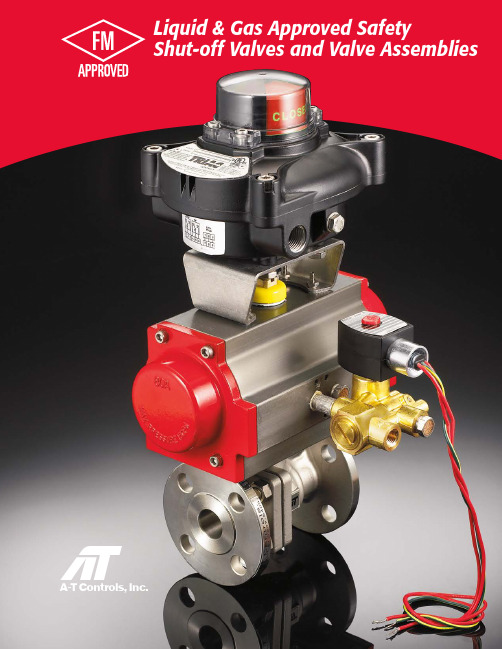
Liquid & Gas Approved SafetyShut-off Valves and Valve AssembliesGas and Oil Safety Shut-offSupervisory Cocksfor liquid and gas shut-offThese assemblies are FM approved for use in applications requiringprotection for fuel burning equipment per FM class 7400, 7412, 7420 and 7422. The components include a spring return automated ball valve, explosion-proof limit switch and solenoid pilot valve. Valves are available in 3-piece or flanged design. The 3-piece design offers threaded, socket weld or butt weld end connections. Flanged valves are available in ANSI Class 150 and 300. Available in sizes 1/4"- 6". Assemblies feature the latest in quarter-turn automation, rack and pinion actuator design; a marked improvement from the olderspring-diaphragm technology. The actuator, combined with the superior valve seating and stem seal design, provides for reliable and consistent closure when needed. Theseassemblies provide for a compact fuel gas safety shut-off system.Valve Assemblies for Gas and Oil Shut-off Requirements• 316SST or WCB valves • 3-piece and flanged valves• Manual safety cocks and automated safety shut-off valves• Solenoid approved for waterproof and explosion-proof environments• Valves feature pyramidal stem seal systemValves andvalve assemblies 2Grafoil PackingBelleville WasherLock SaddleGlandPyramidal (45°) Stem & Stem sealHow to OrderSpecificationsGas Safety Shut-off AssembliesSS-1234567--Manual Safety Cocks AssembliesSC-12345--1 Valve SeriesF88C Series, Firesafe, NACE, 3-piece, Full Port, Direct Mount, Carbon Steel BodyF88 Series, Firesafe, NACE, 3-piece, Full Port, Direct Mount, Stainless Steel BodyFD9C Series, Firesafe, NACE, Flanged, Full Port, Direct Mount, Carbon Steel BodyFD9 Series, Firesafe, NACE, Flanged, Full Port, Direct Mount, Stainless Steel Body8S 8C 9C 9S D9 Series, Flanged, Full Port, Direct Mount, Stainless Steel Body, Oxygen Cleaned and bagged9O2 EndsNPT Connection Socket Weld Butt Weld ANSI Class 150S T B F ANSI Class 30033 Seat MaterialReinforced TFEX4 Valve Size1/4”3/8”1/2”3/4”0380250500751“1001-1/4”1251-1/2”2”2-1/2”3”2001502503004“4006”6006 SolenoidEF8321G1 120 VAC Brass Solenoid EF8321G1 24 VDC Brass Solenoid EV8316G81V 120 VAC SST Solenoid EV8316G81V 24 VDC SST Solenoid B A C D EF8321G1 220 VAC Brass Solenoid EV8316G81V 220 VAC SST SolenoidE F7 Limit SwitchEX10A2SBKN Nema 4, 4X, 7 and 9, 2-SPDT Mechanical, 5 amp @ 125 VAC EX10E2SBKN Nema 4, 4X, 7 and 9, 2-DPDT Mechanical, 5 amp @ 120 VAC EX11D2SBKN Nema 4, 4X, 7 and 9, 2-SPDT Proximity, 1 amp @ 120 VAC E A D EX1TA2SBKN Nema 4, 4X, 7 and 9, 2-SPDT Mechanical, 5 amp @ 125 VAC, 4-20 mA position transmitterT5 Actuator –Pneumatic-Fail Closed60 PSIG air supply available 80 PSIG air supply available863Maximum Operating PressureFlow Data (Cv)Switch Ratings (Amps)88 Series, 3-piece, Full Port, Direct Mount, Stainless Steel Body, Oxygen Cleaned and bagged8O 5 Limit SwitchEX10A2SBKN Nema 4, 4X, 7 and 9, 2-SPDT Mechanical, 5 amp @ 125 VAC EX10E2SBKN Nema 4, 4X, 7 and 9, 2-DPDT Mechanical, 5 amp @ 120 VAC EX11D2SBKN Nema 4, 4X, 7 and 9, 2-SPDT Proximity, 1 amp @ 120 VAC E A D EX1TA2SBKN Nema 4, 4X, 7 and 9, 2-SPDT Mechanical, 5 amp @ 125 VAC, 4-20 mA position transmitterT1 Valve SeriesF88C Series, Firesafe, NACE, 3-piece, Full Port, Direct Mount, Carbon Steel BodyF88 Series, Firesafe, NACE, 3-piece, Full Port, Direct Mount, Stainless Steel BodyFD9C Series, Firesafe, NACE, Flanged, Full Port, Direct Mount, Carbon Steel BodyFD9 Series, Firesafe, NACE, Flanged, Full Port, Direct Mount, Stainless Steel Body8S 8C 9C 9S D9 Series, Flanged, Full Port, Direct Mount, Stainless Steel Body, Oxygen Cleaned and bagged9O2 EndsNPT Connection Socket Weld Butt Weld ANSI Class 150S T B F ANSI Class 30033 Seat MaterialReinforced TFEX88 Series, 3-piece, Full Port, Direct Mount, Stainless Steel Body, Oxygen Cleaned and bagged8O 4 Valve Size1/4”3/8”1/2”3/4”0380250500751“1001-1/4”1251-1/2”2”2-1/2”3”2001502503004“4006”600NOTE: ANY DEVIATIONS FROM STANDARD FM ASSEMBLY OFFERINGS IN THE PRICE BOOK OR LITERATURE WILL VOID THE FM APPROVAL.4Manual Safety Cocks3-PieceE F G7.50 3.94 2.078.00 3.94 2.079.00 6.30 2.0715.5011.81 2.71E F G9.50 3.94 2.0711.12 3.94 2.0712.00 6.30 2.0715.8711.81 2.715Gas Safety Shut-off Assemblies 3-piece6ValveSizeActuatorSR1/4"2R40 3/8"2R40 1/2"2R40 3/4"2R80 1"2R80 1-1/4"2R80 1-1/2"2R130 2"2R200 2-1/2"2R300 3"2R300 4"2R500780 PSI Air SupplyD E F G 7.05 1.84 5.27 4.257.05 2.18 6.51 4.637.05 2.21 6.80 5.007.05 2.838.79 6.507.05 3.389.087.007.05 3.0610.757.507.05 4.0111.408.007.48 4.0713.119.007.487.0018.4015.50A-T Controls, Inc.FM-20180816Copyright 2013 A-T Controls, Inc.LIT0024• FM ApprovedValves and AssembliesSpecial SeatsBalls and Seal DesignsFusible LinkAssembliesLockoutMounting Kits Limit SwitchesMounted on Manual Valves180º ActuatorsStem ExtensionsDual Valve AssembliesFloor MountedDamper DrivesSpecialMulti-Port ValvesWhile you have come to know A-T Controls for superior service in automated valves and day-to-day automation and controls, we specialize in offering solutions to your more unique and difficult applications. Listed below aresome of the specials and solutions oriented products and services we offer.Special End Connections Virtually any Control Accessory Filter RegulatorsSpeed ControlsSolenoidsPneumatic Positioners Electro-pneumatic Positioners Dribble and “Batch” Controls Complete Mounting and Assembly Lockup ValvesDeclutchable Gear Operators Dump Valves Flow Controls Mounting Kits Various MetallurgySpecial Coatings and Treatments Special Tubing and Fittings Alloy Trim9955 International Blvd.Cincinnati, OH 45246PH: 513 - 247- 5465FAX: 513 - 247 - 5462********************Specials and Applied Solutions。
实验室单口供气考克说明(壁式)

科研机构
工业生产
在某些工业生产过程中,需要用到特 定气体进行反应或处理,实验室单口 供气考克(壁式)也可用于这些场景的 气体供应。
适用于各种科研机构的气体实验和研 究,满足科研人员对气体供应的稳定 性和精确性的要求。
02
实验室单口供气考克说明(壁 式)
目录
• 产品概述 • 产品规格与参数 • 产品操作与使用 • 产品维护与保养 • 产品优势与不足
01
产品概述
产品定义
01
实验室单口供气考克(壁式)是一种 用于实验室气体供应的设备,通 常安装在实验室内墙壁上。
02
它通过单口连接管路,为实验室 提供稳定的气体流,用于各种实 验和研究。
产品规格与参数
尺寸与外观
尺寸
壁挂式设计,高度可调,适应不 同实验室空间。
外观
简洁美观,符合现代实验室风格 。
材质与结构
材质
优质不锈钢,经久耐用,防腐蚀。
结构
精密铸造,内部结构优化,确保气流顺畅。
工作压力与流量
工作压力
0.4-0.8 MPa,可根据实际需求调节。
流量
10-50 L/min,可根据实验需求选择。
产品经过严格的质量控制,确 保在使用过程中不会发生泄漏 或意外事故,保障实验室的安 全。
维护方便
壁式单口供气考克结构简单, 方便日常维护和清洁,延长使
用寿命。
不足之处
适用范围有限
由于是单口设计,壁式单口供气考克 只能满足单一仪器或设备的供气需求, 适用范围相对较窄。
无法调节流量
考克不具备流量调节功能,对于需要 不同流量气体的实验场景可能无法满 足需求。
半自动凯式定氮仪安全操作及保养规程
半自动凯式定氮仪安全操作及保养规程一、前言半自动凯式定氮仪是常用于土壤、植物及水体中的氮元素含量测定的高精度仪器设备。
但是在使用过程中,如果不注意维护保养,就会导致测量数据不准确,损害设备的使用寿命,甚至造成人身财产损失。
因此,为了保证设备正常运行,保证实验安全,本文将详细讲解半自动凯式定氮仪的安全操作及保养规程。
二、安全操作1.设备前检查:使用前应检查设备是否损坏,特别是关键部位,如加热器、氮化器等部分。
同时应该检查试剂是否充足、损坏等。
2.操作过程中禁止吸烟3.避免进水:操作过程中,应避免水进入仪器,因为水进入仪器会导致仪器短路,进而导致仪器损坏,测量数据不准确等问题。
4.避免高温:操作过程中,加热器达到极高温度,避免触摸,同时避免将加热器放置在易燃材料周围。
5.防止试剂污染:尽量避免试剂的污染,如果污染则应隔离污染物并及时用试剂清洗污染区域。
6.停机前的工作:在停机前,应按照说明书的要求进行停车程序操作。
如果没有按照说明书或相关要求,设备可能会损坏,数据也可能出现误差。
7.保持周边区域清洁:半自动凯式定氮仪的测量需在通风良好、卫生清洁的环境下进行,如刻意保持周边区域清洁是必要的。
三、保养规程1.清理周边杂物:半自动凯式定氮仪应放置在干燥、通风良好的室内,不能放在湿度过高或有尘埃的地方。
室内环境不宜太潮、必须保持干燥,不要放置其他设备或物品。
2.定期更换机械零部件:仪器长期使用容易出现磨损,因此应该及时替换机械零部件。
3.进行定期检查:为了保证半自动凯式定氮仪的正常使用寿命,应该按照规定的时间进行定期检查,以确保仪器状态良好。
4.避免误差:在使用过程中应注意实验条件,以避免测量数据误差。
在对比数据时,应确保环境条件相同,否则可能导致数据的误差。
5.清洗杂质:使用后需要及时清洗有污渍的零部件,以防止污渍导致仪器故障等问题。
6.对试剂进行合理储存:存放试剂时要避免存放在阳光直射的区域,以避免试剂发生化学反应。
钢研纳克氧氮氢分析仪安全操作及保养规程
钢研纳克氧氮氢分析仪安全操作及保养规程钢研纳克氧氮氢分析仪是一种用于分析和检测氧氮氢等元素含量的仪器。
为了确保正常操作和延长仪器的使用寿命,需要严格遵守安全操作规程并进行适当的保养。
本文档将详细介绍钢研纳克氧氮氢分析仪的安全操作及保养规程。
1. 安全操作规程1.1 电源安全•在使用钢研纳克氧氮氢分析仪之前,确保仪器所连接的电源稳定且接地正常。
切勿使用带有破损的电源线或插座。
•需要按照供应商提供的电源要求,选择正确的电源电压,并使用对应的电源线。
•在检查或维修仪器时,务必将电源线拔出。
1.2 仪器操作•仪器应该放置在稳定且通风良好的位置。
•在操作仪器之前,仔细阅读该仪器的用户手册,并按照手册中的操作步骤进行操作。
•在操作仪器过程中,切勿触摸不应触摸的部位,防止发生触电或其他危险情况。
•所有的操作都应该小心谨慎,避免额外的冲击、摇晃或其他不必要的动作。
1.3 气体安全•使用纯净的氮气、氧气和氢气,确保气源的纯度和质量。
•在连接气源之前,检查气源管道是否安全、密封且无泄漏。
•在打开气源阀门之前,确保漏气检测器显示无气体泄漏。
•使用仪器期间,保持仪器周围的工作区域干燥且无可燃物。
•禁止在仪器周围吸烟、点火或使用易燃物品。
2. 仪器保养规程2.1 定期清洁•定期清洁仪器的外表面,可以使用柔软的布擦拭,避免使用有腐蚀性的化学溶剂。
•清洁仪器的传感器和探头是保持精确测量的关键。
根据仪器的说明书,定期清洗并校准这些部分。
•清洗传感器和探头时,应该使用适当的溶液,并遵循操作手册中的建议。
2.2 定期校准•定期校准仪器以确保准确性和精度。
根据仪器的规格要求,定期进行内部和外部校准。
•在校准仪器之前,需要根据供应商的建议准备相应的校准溶液和标准样品。
2.3 适当的存储•当仪器不使用时,应将其存放在干燥、无灰尘和正常温度的地方。
•避免将仪器暴露在过高或过低的温度下,以免损坏仪器的电子组件。
•长时间不使用时,应将仪器放入专用的防尘罩中,以防尘污和损坏。
Gasmaster气体火灾监测控制器1或4路 英国科尔康CROWCON报警控制主机
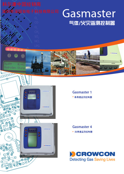
Gasmaster 1•单通道监测控制器Gasmaster 4• 四通道监测控制器GasmasterGasmaster是一款可用于监测气体和火灾,使用灵活、操作简便的控制器。
Gasmaster功能强大、性能卓越,能够满足各类工业应用。
它监测信息全面,显示一目了然,更改设置可完全通过前面板上按键实现。
Gasmaster能够单独运行,也可以配置继电器或通讯接口输出连接报警设备和控制系统。
简单方便• G asmaster设计保证操作简单。
所有气体浓度和状态信息都能在一瞥之间全部掌握,系统具有自检功能。
• G asmaster从日常操作到校准的所有功能都能通过前面板进行操作,方便快捷。
• G asmaster PC 软件能够迅速重新配置系统和上传数据记录。
• Gasmaster安装和维护极其方便,预留接线空间大,便于连接电缆。
• Gasmaster具有校准过期提醒功能。
一键式操作快速检测全部的输入输出。
安全可靠•Gasmaster每个通道有2个报警等级,同时配备公共报警和故障继电器,Gasmaster可以按照现场要求进行配置,装备一个标准的85分贝多音频报警器来对应不同报警等级。
•继电器工作在故障安全模式下,Gasmaster所有继电器模块均处于被监测状态,一旦发生故障立即报警。
•Gasmaster不必担心电源故障问题,备用电池保证电源故障情况下系统正常运转。
•报警和故障记录在“事件日志”里,便于定期进行现场风险评估。
输入输出配置灵活• G asmaster可以连接多种气体和火灾探头。
提供多种输出以便以最少的接线量与各类控制系统通讯。
• G asmaster配置有继电器输出,可驱动声光报警,还提供4-20mA、1-5V标准输出以及RS-485Modbus通讯协议,可满足复杂的监测和控制。
• G asmaster的远程禁止和远程复位功能,使人员在控制室就能对任何一点进行操控。
• G asmaster1级报警可以设置成静音模式,执行机构可以在没有报警音的情况下自动启动。
二甲醚分析仪安全操作规定
二甲醚分析仪安全操作规定1. 前言二甲醚分析仪是一种用于检测二甲醚浓度的特殊设备,用于保障工作场所和公共环境中人们的健康,因此在操作过程中必须严格遵守安全规定,以避免意外发生。
本文将介绍二甲醚分析仪的安全操作规定。
2. 操作环境2.1 温度二甲醚分析仪的操作环境应该在5°C至45°C的范围内。
2.2 相对湿度操作环境的相对湿度应该在10%至90%的范围内。
2.3 操作场所此类仪器应该在无腐蚀性和易燃气体、液体的操作环境中使用。
使用场所应远离污染严重的区域,如废气排放口或有毒有害气体源等。
3. 操作规范3.1 安装在安装仪器时,应按照使用说明书中的要求进行操作,并保证其处于平稳的工作状态。
3.2 校准在校准仪器之前,工作人员必须先检查所有传感器和仪器部件是否完好无损,同时应进行线路检查和通风检查。
3.3 操作在操作二甲醚分析仪之前,应使用防震底座放置仪器,并保持仪器放置水平。
在操作过程中,不要在仪器上放置任何物品,尤其是易燃、易爆物品。
在操作中,应注意保持仪器洁净,避免对仪器内部或外部造成污染。
3.4 关闭使用完毕后,应先按照要求关闭仪器内的所有开关。
然后再切断电源并将仪器从电源上断开。
4. 预防措施4.1 保持清洁保持二甲醚分析仪清洁对仪器的正常工作至关重要。
在日常操作中,应将仪器表面清洁干净,以防止灰尘和其他物质进入设备。
4.2 安全检查在使用前,应进行仔细的安全检查,以确保它处于安全的工作状态。
在操作仪器时,应注意不要损坏仪器零件或者伤害到自己或他人。
4.3 正确保管在使用完毕后,应将二甲醚分析仪正确放置。
在未使用的情况下,应将设备存放在干燥通风处,远离易燃、易爆、腐蚀性物质和湿度较大的环境。
5. 总结二甲醚分析仪是一种非常重要的检测仪器,对于工作安全和人类健康至关重要。
因此,在操作这种仪器时,必须完全遵照操作规范,采用正确、安全的方式进行操作和保管设备以及仪器校准,确保设备的长期稳定和安全性。
- 1、下载文档前请自行甄别文档内容的完整性,平台不提供额外的编辑、内容补充、找答案等附加服务。
- 2、"仅部分预览"的文档,不可在线预览部分如存在完整性等问题,可反馈申请退款(可完整预览的文档不适用该条件!)。
- 3、如文档侵犯您的权益,请联系客服反馈,我们会尽快为您处理(人工客服工作时间:9:00-18:30)。
当打开煤气时 填写煤气使用记录
* 后附煤气使用控制表
全面检查煤气 设备的情况
操作过程中 随时检查
如果有问题 及时报告
* 见工程请修单程序此步骤的细节 (k # 011)
在厨房日志上 记录使用过程
关掉 煤气开关
* 使用完毕后
关掉煤气时在 煤气使用记录上签字
备注 : 煤气安全控制是每一个员工的职责 , 每一位员工都要检查煤气设备的工作情况 如果有任何安全隐患或火灾立刻报告中厨厨师长和保卫部 . 根据安全规则 , 管事部负责正确清洁所有炉具以避免引起火灾 .