Modeling IT Operations to Derive Provider Accepted Management Tools
Requirements engineering (RE) is concerned with the identification

Requirements Engineering in the Year 00: A Research PerspectiveAxel van LamsweerdeDépartement d’Ingénierie InformatiqueUniversité catholique de LouvainB-1348 Louvain-la-Neuve (Belgium)avl@info.ucl.ac.beABSTRACTRequirements engineering(RE)is concerned with the iden-tification of the goals to be achieved by the envisioned sys-tem,the operationalization of such goals into services and constraints,and the assignment of responsibilities for the resulting requirements to agents such as humans,devices, and software.The processes involved in RE include domain analysis,elicitation,specification,assessment, negotiation,documentation,and evolution.Getting high-quality requirements is difficult and critical.Recent surveys have confirmed the growing recognition of RE as an area of utmost importance in software engineering research and practice.The paper presents a brief history of the main concepts and techniques developed to date to support the RE task,with a special focus on modeling as a common denominator to all RE processes.The initial description of a complex safety-critical system is used to illustrate a number of current research trends in RE-specific areas such as goal-oriented requirements elaboration,conflict management,and the handling of abnormal agent behaviors.Opportunities for goal-based architecture derivation are also discussed together with research directions to let thefield move towards more disciplined habits.1. INTRODUCTIONSoftware requirements have been repeatedly recognized during the past25years to be a real problem.In their early empirical study,Bell and Thayer observed that inadequate, inconsistent,incomplete,or ambiguous requirements are numerous and have a critical impact on the quality of the resulting software[Bel76].Noting this for different kinds of projects,they concluded that“the requirements for a system do not arise naturally;instead,they need to be engineered and have continuing review and revision”.Boehm esti-mated that the late correction of requirements errors could cost up to200times as much as correction during such requirements engineering[Boe81].In his classic paper on the essence and accidents of software engineering,Brooks stated that“the hardest single part of building a sofware system is deciding precisely what to build...Therefore,the most important function that the software builder performs for the client is the iterative extraction and refinement of the product requirements”[Bro87].In her study of software errors in NASA’s V oyager and Galileo programs,Lutz reported that the primary cause of safety-related faults was errors in functional and interface requirements [Lut93]. Recent studies have confirmed the requirements problem on a much larger scale.A survey over8000projects under-taken by350US companies revealed that one third of the projects were never completed and one half succeeded only partially,that is,with partial functionalities,major cost overruns,and significant delays[Sta95].When asked about the causes of such failure executive managers identifed poor requirements as the major source of problems(about half of the responses)-more specifically,the lack of user involve-ment(13%),requirements incompleteness(12%),changing requirements(11%),unrealistic expectations(6%),and unclear objectives(5%).On the European side,a recent sur-vey over3800organizations in17countries similarly con-cluded that most of the perceived software problems are in the area of requirements specification(>50%)and require-ments management (50%) [ESI96].Improving the quality of requirements is thus crucial.But it is a difficult objective to achieve.To understand the reason one shouldfirst define what requirements engineering is really about.The oldest definition already had the main ingredients.In their seminal paper,Ross and Schoman stated that“require-ments definition is a careful assessment of the needs that a system is to fulfill.It must say why a system is needed,based on current or foreseen conditions,which may be internal operations or an external market.It must say what system features will serve and satisfy this context.And it must say how the system is to be constructed”[Ros77b].In other words,requirements engineering must address the contex-tual goals why a software is needed,the functionalities the software has to accomplish to achieve those goals,and the constraints restricting how the software accomplishing those functions is to be designed and implemented.Such goals,functions and constraints have to be mapped to pre-cise specifications of software behavior;their evolution over time and across software families has to be coped with as well [Zav97b].This definition suggests why the process of engineering requirements is so complex.•The scope is fairly broad as it ranges from a world of human organizations or physical laws to a technical arti-fact that must be integrated in it;from high-level objec-tives to operational prescriptions;and from informal to formal.The target system is not just a piece of software,Invited paper for ICSE’2000 - To appear inLimerick, June 2000, ACM PressProc. 22nd International Conference on Software Engineering,but also comprises the environment that will surround it; the latter is made of humans,devices,and/or other soft-ware.The whole system has to be considered under many facets,e.g.,socio-economic,physical,technical,opera-tional, evolutionary, and so forth.•There are multiple concerns to be addressed beside func-tional ones-e.g.,safety,security,usability,flexibility,per-formance,robustness,interoperability,cost, maintainability,and so on.These non-functional concerns are often conflicting.•There are multiple parties involved in the requirements engineering process,each having different background, skills,knowledge,concerns,perceptions,and expression means-namely,customers,commissioners,users,domain experts,requirements engineers,software developers,or system maintainers.Most often those parties have conflict-ing viewpoints.•Requirement specifications may suffer a great variety of deficiencies[Mey85].Some of them are errors that may have disastrous effects on the subsequent development steps and on the quality of the resulting software product-e.g.,inadequacies with respect to the real needs,incom-pletenesses,contradictions,and ambiguities;some others areflaws that may yield undesired consequences(such as waste of time or generation of new errors)-e.g.,noises, forward references,overspecifications,or wishful thinking.•Requirements engineering covers multiple intertwined activities.–Domain analysis:the existing system in which the soft-ware should be built is studied.The relevant stakehold-ers are identified and interviewed.Problems and deficiencies in the existing system are identified;oppor-tunities are investigated;general objectives on the target system are identified therefrom.–Elicitation:alternative models for the target system are explored to meet such objectives;requirements and assumptions on components of such models are identi-fied,possibly with the help of hypothetical interaction scenarios.Alternative models generally define different boundaries between the software-to-be and its environ-ment.–Negotiation and agreement:the alternative require-ments/assumptions are evaluated;risks are analyzed;"best"tradeoffs that receive agreement from all parties are selected.–Specification:the requirements and assumptions are for-mulated in a precise way.–Specification analysis:the specifications are checked for deficiencies(such as inadequacy,incompleteness or inconsistency)and for feasibility(in terms of resources required, development costs, and so forth).–Documentation:the various decisions made during the process are documented together with their underlying rationale and assumptions.–Evolution:the requirements are modified to accommo-date corrections,environmental changes,or new objec-tives.Given such complexity of the requirements engineering pro-cess,rigorous techniques are needed to provide effective support.The objective of this paper is to provide:a brief his-tory of25years of research efforts along that way;a concrete illustration of what kind of techniques are available today; and directions to be explored for requirements engineering to become a mature discipline.The presentation will inevitably be biased by my own work and background.Although the area is inherently interdisci-plinary,I will deliberately assume a computing science viewpoint here and leave the socological and psychological dimensions aside(even though they are important).In partic-ular,I will not cover techniques for ethnographic observation of work environments,interviewing,negotiation,and so forth.The interested reader may refer to[Gog93,Gog94]for a good account of those dimensions.A comprehensive,up-to-date survey on the intersecting area of information model-ing can be found in [Myl98].2. THE FIRST 25 YEARS: A FEW RESEARCHMILESTONESRequirements engineering addresses a wide diversity of domains(e.g.,banking,transportation,manufacturing),tasks (e.g.,administrative support,decision support,process con-trol)and environments(e.g.,human organizations,physical phenomena).A specific domain/task/environment may require some specific focus and dedicated techniques.This is in particular the case for reactive systems as we will see after reviewing the main stream of research..Modeling appears to be a core process in requirements engi-neering.The existing system has to be modelled in some way or another;the alternative hypothetical systems have to be modelled as well.Such models serve as a basic common interface to the various activities above.On the one hand, they result from domain analysis,elicitation,specification analysis,and negotiation.On the other hand,they guide fur-ther domain analysis,elicitation,specification analysis,and negotiation.Models also provide the basis for documenta-tion and evolution.It is therefore not surprising that most of the research to date has been devoted to techniques for mod-eling and specification.The basic questions that have been addressed over the years are:•what aspects to model in the why-what-how range,•how to model such aspects,•how to define the model precisely,•how to reason about the model.The answer to thefirst question determines the ontology of conceptual units in terms of which models will be built-e.g., data,operations,events,goals,agents,and so forth.The answer to the second question determines the structuring relationships in terms of which such units will be composed and linked together-e.g.,input/output,trigger,generaliza-tion,refinement,responsibility assignment,and so forth.The answer to the third question determines the informal,semi-formal,or formal specification technique used to define the required properties of model components precisely.The answer to the fourth question determines the kind of reason-ing technique available for the purpose of elicitation,specifi-cation, and analysis.The early daysThe seminal paper by Ross and Schoman opened thefield [Ros97b].Not only did this paper comprehensively explain the scope of requirements engineering;it also suggested goals,viewpoints,data,operations,agents,and resources as potential elements of an ontology for RE.The companion paper introduced SADT as a specific modeling technique [Ros97a].This technique was a precursor in many respects. It supported multiple models linked through consistency rules-a model for data,in which data are defined by produc-ing/consuming operations;a model for operations,in which operations are defined by input/output data;and a data/oper-ation duality principle.The technique was ontologically richer than many techniques developed afterwards.In addi-tion to data and operations,it supported some rudimentary representation of events,triggering operations,and agents responsible for them.The technique also supported the step-wise refinement of global models into more detailed ones-an essential feature for complex models.SADT was a semi-formal technique in that it could only support the formaliza-tion of the declaration part of the system under consideration -that is,what data and operations are to be found and how they relate to each other;the requirements on the data/opera-tions themselves had to be asserted in natural language.The semi-formal language,however,was graphical-an essential feature for model communicability.Shortly after,Bubenko introduced a modeling technique for capturing entities and events.Formal assertions could be written to express requirements about them,in particular, temporal constraints[Bub80].At that time it was already recognized that such entities and events had to take part in the real world surrounding the software-to-be [Jac78]. Other semi-formal techniques were developed in the late seventies,notably,entity-relationship diagrams for the mod-eling of data[Che76],structured analysis for the stepwise modeling of operations[DeM78],and state transition dia-grams for the modeling of user interaction[Was79].The popularity of those techniques came from their simplicity and dedication to one specific concern;the price to pay was their fairly limited scope and expressiveness,due to poor underlying ontologies and limited structuring facilities. Moreover they were rather vaguely defined.People at that time started advocating the benefits of precise and formal specifications,notably,for checking specification adequacy through prototyping [Bal82].RML brought the SADT line of research significantly further by introducing rich structuring mechanisms such as generali-zation,aggregation and classification[Gre82].In that sense it was a precursor to object-oriented analysis techniques. Those structuring mechanisms were applicable to three kinds of conceptual units:entities,operations,and con-straints.The latter were expressed in a formal assertion lan-guage providing,in particular,built-in constructs for temporal referencing.That was the time where progress in database modeling[Smi77],knowledge representation [Bro84,Bra85],and formal state-based specification [Abr80]started penetrating ourfield.RML was also proba-bly thefirst requirements modeling language to have a for-mal semantics,defined in terms of mappings tofirst-order predicate logic [Gre86].Introducing agentsA next step was made by realizing that the software-to-be and its environment are both made of active components. Such components may restrict their behavior to ensure the constraints they are assigned to.Feather’s seminal paper introduced a simple formal framework for modeling agents and their interfaces,and for reasoning about individual choice of behavior and responsibility for constraints[Fea87]. Agent-based reasoning is central to requirements engineer-ing since the assignment of responsibilities for goals and constraints among agents in the software-to-be and in the environment is a main outcome of the RE process.Once such responsibilities are assigned the agents have contractual obligations they need to fulfill[Fin87,Jon93,Ken93]. Agents on both sides of the software-environment boundary interact through interfaces that may be visualized through context diagrams [War85].Goal-based reasoningThe research efforts so far were in the what-how range of requirements engineering.The requirements on data and operations were just there;one could not capture why they were there and whether they were sufficient for achieving the higher-level objectives that arise naturally in any require-ments engineering process[Hic74,Mun81,Ber91,Rub92]. Yue was probably thefirst to argue that the integration of explicit goal representations in requirements models pro-vides a criterion for requirements completeness-the require-ments are complete if they are sufficient to establish the goal they are refining[Yue87].Broadly speaking,a goal corre-sponds to an objective the system should achieve through cooperation of agents in the software-to-be and in the envi-ronment.Two complementary frameworks arose for integrating goals and goal refinements in requirements models:a formal framework and a qualitative one.In the formal framework [Dar91],goal refinements are captured through AND/OR graph structures borrowed from problem reduction tech-niques in artificial intelligence[Nil71].AND-refinement links relate a goal to a set of subgoals(called refinement); this means that satisfying all subgoals in the refinement is a sufficient condition for satisfying the goal.OR-refinement links relate a goal to an alternative set of refinements;this means that satisfying one of the refinements is a sufficient condition for satisfying the goal.In this framework,a con-flict link between goals is introduced when the satisfaction of one of them may preclude the satisfaction of the others. Operationalization links are also introduced to relate goals to requirements on operations and objects.In the qualitative framework[Myl92],weaker versions of such link types are introduced to relate“soft”goals[Myl92].The idea is that such goals can rarely be said to be satisfied in a clear-cut sense.Instead of goal satisfaction,goal satisficing is intro-duced to express that lower-level goals or requirements are expected to achieve the goal within acceptable limits,ratherthan absolutely.A subgoal is then said to contribute partially to the goal,regardless of other subgoals;it may contribute positively or negatively.If a goal is AND-decomposed into subgoals and all subgoals are satisficed,then the goal is sat-isficeable;but if a subgoal is denied then the goal is deniable. If a goal contributes negatively to another goal and the former is satisficed, then the latter is deniable.The formal framework gave rise to the KAOS methodology for eliciting,specifying,and analyzing goals,requirements, scenarios,and responsibility assignments[Dar93].An optional formal assertion layer was introduced to support various forms of formal reasoning.Goals and requirements on objects are formalized in a real-time temporal logic [Man92,Koy92];one can thereby prove that a goal refine-ment is correct and complete,or complete such a refinement [Dar96].One can also formally detect conflicts among goals [Lam98b]or generate high-level exceptions that may prevent their achievement[Lam98a].Requirements on operations are formalized by pre-,post-,and trigger conditions;one can thereby establish that an operational requirement“imple-ments”higher-level goals[Dar93],or infer such goals from scenarios [Lam98c].The qualitative framework gave rise to the NFR methodol-ogy for capturing and evaluating alternative goal decomposi-tions.One may see it as a cheap alternative to the formal framework,for limited forms of goal-based reasoning,and as a complementary framework for high-level goals that can-not be formalized.The labelling procedure in[Myl92]is a typical example of qualitative reasoning on goals specified by names,parameters,and degrees of satisficing/denial by child goals.This procedure determines the degree to which a goal is satisficed/denied by lower-level requirements,by propagating such information along positive/negative sup-port links in the goal graph.The strength of those goal-based frameworks is that they do not only cover functional goals but also non-functional ones; the latter give rise to a wide range of non-functional require-ments.For example,[Nix93]showed how the NFR frame-work could be used to qualitatively reason about performance requirements during the RE and design phases. Informal analysis techniques based on similar refinement trees were also proposed for specific types of non-functional requirements,such as fault trees[Lev95]and threat trees [Amo94]for exploring safety and security requirements, respectively.Goal and agent models can be integrated through specific links.In KAOS,agents may be assigned to goals through AND/OR responsibility links;this allows alternative bound-aries to be investigated between the software-to-be and its environment.A responsibility link between an agent and a goal means that the agent can commit to perform its opera-tions under restricted pre-,post-,and trigger conditions that ensure the goal[Dar93].Agent dependency links were defined in[YuM94,Yu97]to model situations where an agent depends on another for a goal to be achieved,a task to be accomplished,or a resource to become available.For each kind of dependency an operator is defined;operators can be combined to define plans that agents may use to achieve goals.The purpose of this modeling is to support the verification of properties such as the viability of an agent's plan or the fulfilment of a commitment between agents. Viewpoints, facets, and conflictsBeside the formal and qualitative reasoning techniques above,other work on conflict management has emphasized the need for handling conflicts at the goal level.A procedure was suggested in[Rob89]for identifying conflicts at the requirements level and characterizing them as differences at goal level;such differences are resolved(e.g.,through nego-tiation)and then down propagated to the requirements level. In[Boe95],an iterative process model was proposed in which(a)all stakeholders involved are identified together with their goals(called win conditions);(b)conflicts between these goals are captured together with their associ-ated risks and uncertainties;and(c)goals are reconciled through negotiation to reach a mutually agreed set of goals, constraints, and alternatives for the next iteration.Conflicts among requirements often arise from multiple stakeholders viewpoints[Eas94].For sake of adequacy and completeness during requirements elicitation it is essential that the viewpoints of all parties involved be captured and eventually integrated in a consistent way.Two kinds of approaches have emerged.They both provide constructs for modeling and specifying requirements from different view-points in different notations.In the centralized approach,the viewpoints are translated into some logic-based“assembly”language for global analysis;viewpoint integration then amounts to some form of conjunction[Nis89,Zav93].In the distributed approach,viewpoints have specific consistency rules associated with them;consistency checking is made by evaluating the corresponding rules on pairs of viewpoints [Nus94].Conflicts need not necessarily be resolved as they arise;different viewpoints may yield further relevant infor-mation during elicitation even though they are conflicting in some respect.Preliminary attempts have been made to define a paraconsistent logical framework allowing useful deduc-tions to be made in spite of inconsistency [Hun98]. Multiparadigm specification is especially appealling for requirements specification.In view of the broad scope of the RE process and the multiplicity of system facets,no single language will ever serve all purposes.Multiparadigm frame-works have been proposed to combine multiple languages in a semantically meaningful way so that different facets can be captured by languages thatfit them best.OMT’s combina-tion of entity-relationship,dataflow,and state transition dia-grams was among thefirst attempts to achieve this at a semi-formal level[Rum91].The popularity of this modeling tech-nique and other similar ones led to the UML standardization effort[Rum99].The viewpoint construct in[Nus94]pro-vides a generic mechanism for achieving such combinations. Attempts to integrate semi-formal and formal languages include[Zav96],which combines state-based specifications [Pot96]andfinite state machine specifications;and[Dar93], which combines semantic nets[Qui68]for navigating through multiple models at surface level,temporal logic for the specification of the goal and object models[Man92, Koy92],and state-based specification[Pot96]for the opera-tion model.Scenario-based elicitation and validationEven though goal-based reasoning is highly appropriate for requirements engineering,goals are sometimes hard to elicit. Stakeholders may have difficulties expressing them in abstracto.Operational scenarios of using the hypothetical system are sometimes easier to get in thefirst place than some goals that can be made explicit only after deeper understanding of the system has been gained.This fact has been recognized in cognitive studies on human problem solving[Ben93].Typically,a scenario is a temporal sequence of interaction events between the software-to-be and its environment in the restricted context of achieving some implicit purpose(s).A recent study on a broader scale has confirmed scenarios as important artefacts used for a variety of purposes,in particular in cases when abstract modeling fails[Wei98].Much research effort has therefore been recently put in this direction[Jar98].Scenario-based techniques have been proposed for elicitation and for valida-tion-e.g.,to elicit requirements in hypothetical situations [Pot94];to help identify exceptional cases[Pot95];to popu-late more abstract conceptual models[Rum91,Rub92];to validate requirements in conjunction with prototyping [Sut97],animation[Dub93],or plan generation tools [Fic92]; to generate acceptance test cases [Hsi94].The work on deficiency-driven requirements elaboration is especially worth pointing out.A system there is specified by a set of goals(formalized in some restricted temporal logic), a set of scenarios(expressed in a Petri net-like language), and a set of agents producing restricted scenarios to achieve the goals they are assigned to.The technique is twofold:(a) detect inconsistencies between scenarios and goals;(b) apply operators that modify the specification to remove the inconsistencies.Step(a)is carried out by a planner that searches for scenarios leading to some goal violation. (Model checkers might probably do the same job in a more efficient way[McM93,Hol97,Cla99].)The operators offered to the analyst in Step(b)encode heuristics for speci-fication debugging-e.g.,introduce an agent whose responsi-bility is to prevent the state transitions that are the last step in breaking the goal.There are operators for introducing new types of agents with appropriate responsibilities,splitting existing types,introducing communication and synchroniza-tion protocols between agents,weakening idealized goals, and so forth.The repeated application of deficiency detec-tion and debugging operators allows the analyst to explore the space of alternative models and hopefully converge towards a satisfactory system specification.The problem with scenarios is that they are inherently par-tial;they raise a coverage problem similar to test cases,mak-ing it impossible to verify the absence of errors.Instance-level trace descriptions also raise the combinatorial explo-sion problem inherent to the enumeration of combinations of individual behaviors.Scenarios are generally procedural, thus introducing risks of overspecification.The description of interaction sequences between the software and its envi-ronment may force premature choices on the precise bound-ary between st but not least,scenarios leave required properties about the intended system implicit,in the same way as safety/liveness properties are implicit in a pro-gram trace.Work has therefore begun on inferring goal/ requirement specifications from scenarios in order to support more abstract, goal-level reasoning [Lam98c].Back to groundworkIn parallel with all the work outlined above,there has been some more fundamental work on clarifying the real nature of requirements[Jac95,Par95,Zav97].This was motivated by a certain level of confusion and amalgam in the literature on requirements and software specifications.At about the same time,Jackson and Parnas independently made afirst impor-tant distinction between domain properties(called indicative in[Jac95]and NAT in[Par95])and requirements(called optative in[Jac95]and REQ in[Par95]).Such distinction is essential as physical laws,organizational policies,regula-tions,or definitions of objects or operations in the environ-ment are by no means requirements.Surprisingly,the vast majority of specification languages existing to date do not support that distinction.A second important distinction made by Jackson and Parnas was between(system)require-ments and(software)specifications.Requirements are for-mulated in terms of objects in the real world,in a vocabulary accessible to stakeholders[Jac95];they capture required relations between objects in the environment that are moni-tored and controlled by the software,respectively[Par95]. Software specifications are formulated in terms of objects manipulated by the software,in a vocabulary accessible to programmers;they capture required relations between input and output software objects.Accuracy goals are non-func-tional goals requiring that the state of input/output software objects accurately reflect the state of the corresponding mon-itored/controlled objects they represent[Myl92,Dar93]. Such goals often are to be achieved partly by agents in the environments and partly by agents in the software.They are often overlooked in the RE process;their violation may lead to major failures[LAS93,Lam2Ka].A further distinction has to be made between requirements and assumptions. Although they are both optative,requirements are to be enforced by the software whereas assumptions can be enforced by agents in the environment only[Lam98b].If R denotes the set of requirements,As the set of assumptions,S the set of software specifications,Ac the set of accuracy goals,and G the set of goals,the following satisfaction rela-tions must hold:S, Ac, D|== R with S, Ac, D|=/=falseR, As, D|== G with R, As, D|=/=falseThe reactive systems lineIn parallel with all the efforts discussed above,a dedicated stream of research has been devoted to the specific area of reactive systems for process control.The seminal paper here was based on work by Heninger,Parnas and colleagues while reengineering theflight software for the A-7aircraft [Hen80].The paper introduced SCR,a tabular specification technique for specifying a reactive system by a set of parallel finite-state machines.Each of them is defined by different types of mathematical functions represented in tabular for-mat.A mode transition table defines a mode(i.e.a state)as a transition function of a mode and an event;an event table defines an output variable(or auxiliary quantity)as a func-。
大数据的影响英文介绍作文

大数据的影响英文介绍作文Title: The Impact of Big Data: Revolutionizing the Future。
In the digital age, the advent of big data has usheredin a new era of innovation and transformation acrossvarious sectors. Big data, characterized by its vast volume, high velocity, and diverse variety, has profoundlyinfluenced numerous aspects of our lives, ranging from business and healthcare to education and governance. This essay delves into the multifaceted impact of big data, exploring its implications and opportunities for the future.One of the most significant effects of big data lies in its capacity to revolutionize decision-making processes. Through advanced analytics and predictive modeling, bigdata enables organizations to derive actionable insights from massive datasets in real-time. By leveraging these insights, businesses can make informed strategic decisions, optimize operations, and gain a competitive edge in themarket. For instance, retailers can analyze customer purchasing patterns to personalize marketing campaigns, leading to higher customer engagement and increased sales revenue.Furthermore, big data plays a crucial role in driving innovation and fostering technological advancements. The wealth of data generated from various sources, including social media, sensors, and online transactions, serves as a valuable resource for research and development. Machine learning algorithms and artificial intelligence algorithms can analyze this data to uncover hidden patterns,facilitate product innovation, and fuel the creation of disruptive technologies. For example, in the healthcare sector, big data analytics is instrumental in drug discovery, disease diagnosis, and personalized medicine, leading to improved patient outcomes and enhanced healthcare delivery.Moreover, big data has transformative implications for society as a whole, particularly in the realm of governance and public policy. Government agencies can harness big dataanalytics to enhance decision-making processes, improve service delivery, and address societal challenges more effectively. By analyzing data related to transportation, urban planning, and public health, policymakers can develop evidence-based policies and interventions that better meet the needs of citizens. Additionally, big data enables greater transparency and accountability in governance by providing insights into government operations and expenditures, thereby fostering public trust and participation in democratic processes.However, alongside its myriad benefits, big data also raises important ethical, privacy, and security concerns. The collection and analysis of vast amounts of personal data raise questions about individual privacy rights and data protection. Moreover, the potential for data breaches and cyberattacks poses significant risks to data security and confidentiality. As such, it is imperative for organizations and policymakers to implement robust data governance frameworks, security measures, and ethical guidelines to safeguard against misuse and abuse of data.In conclusion, big data represents a transformative force that is reshaping the way we live, work, and interact with the world around us. From enabling data-driven decision-making and fostering innovation to enhancing governance and public policy, the impact of big data is profound and far-reaching. However, realizing the full potential of big data requires a concerted effort to address ethical, privacy, and security concerns, ensuring that its benefits are equitably distributed and responsibly managed. As we continue to harness the power of big data, we have the opportunity to unlock new possibilities and create a more prosperous and sustainable future for generations to come.。
Modeling power line icing in freezing precipitation

Modeling power line icing in freezing precipitationLasse MakkonenVTT Building Technology, Technical Research Centre of Finland, Box 18071, 02044 VTT, FinlandAvailable online 25 November 1998.AbstractThe existing widely used models of power line icing in freezing precipitation are conceptually evaluated.The reasons for the different predictions by the models are pointed out, and it is shown that none of the models is both correct and complete in predicting design glaze ice loads. Improvements to the modeling are proposed and a new comprehensive numerical model is presented. This model includes detailed simulation of icicle growth. The results of the new model show that earlier models underestimate ice loads under certain conditions. Furthermore, the new model shows that ice loads formed close to 0°C may be much higher than those formed at lower temperatures, other conditions being the same.Keywords: Icing; Freezing precipitation; Freezing rain; Glaze; Ice loads; Power lines; IciclesArticle Outline∙ 1. Introduction∙ 2. The problem∙ 3. Model evaluations∙o 3.1. Imai modelo 3.2. Lenhard modelo 3.3. Goodwin et al. modelo 3.4. Chainé and Castonguay modelo 3.5. Numerical glaze icing modelso 3.6. Summary of model evaluation∙ 4. A new comprehensive model∙ 5. Discussion∙Acknowledgements∙References1. IntroductionIn many regions, freezing precipitation is the basis for the design ice load of power lines. Consequently, attempts to theoretically estimate glaze ice loads based on weather data have been made for over 50 years.This period has, however, not been sufficient to show which of the proposed freezing precipitation models is preferable. Still today, there are various models used operationally and in theoretical studies (Imai, 1953; Lenhard, 1955; Chainé and Castonguay, 1974; Anon, 1984; Goodwin et al., 1983; Lozowski et al., 1983; Makkonen, 1984; Finstad et al., 1988; Szilder, 1994; [Anon, 1977. Ontario Hydro wind and ice loading model. Meteorology Research Report MRI 77 FR-1496, (unpublished)]). Attempts have recently been made to systematically compare the models as `black boxes' against specially collected data for individual icing events (Krishnasamy and Brown, 1986 and Krishnasamy et al., 1993;Felin, 1988; McComber et al., 1993; Yip, 1993). However, the models require different and sometimes missing input parameters, which makes objective comparisons by this method difficult. Also, the data sets seldom include the extreme situations. The models that behave well in limited tests of this kind may not be the ones that predict correctly in the rare extreme conditions that are of interest in structural design. Thus, it is necessary to `open the black boxes' and consider the expected applicability of the various models from a theoretical point of view.In this paper the existing models of power line icing in freezing precipitation are conceptually evaluated. The essential assumptions, the logical concepts, the correctness of mathematical formulas and the completeness of the physics described are considered. A new comprehensive numerical model is then proposed.2. The problemWhen significant liquid precipitation occurs at freezing temperatures glaze ice will form. We consider here the physics of the icing process. A discussion of the meteorological conditions resulting in freezing precipitation can be found elsewhere (e.g., Stallabrass, 1983). It is noteworthy, however, that the structure of the atmospheric boundary-layer is exceptional in these conditions, so that model results may not be readily extrapolated to other heights in the case of tall structures or hilly areas.The process to be modelled is schematically shown in Fig. 1. In order to simulate the process theoretically, one obviously needs to know at least the cable radius R0, the precipitation intensity I, and the wind speed V. More detailed modeling requires the angle θ between the cable orientation and thewind, and the fall speed of the drops V d, so that the drop impact velocity vector can be determined.Using , the flux density F=WV i of impinging water may be calculated if the liquid water content W in the air is known. The latter can be calculated from W=ρW I/V d, where ρW is the water density. The drop fall velocity V d can be determined from empirical expressions relating V d, the drop size distributionand I (e.g., Stallabrass, 1983).Full-size image (9K) Fig. 1.Icing in freezing rain.In freezing rain the drops are so big that the drop collision efficiency may be taken as unity. However, the water collected by the cable may not freeze on the surface, but may be partly lost by shedding. On the other hand, all the run-back water is not typically lost directly. Instead, icicles will grow. The icicles, in turn, offer an additional surface for collecting the wind driven drops, thus increasing the total impinging flux. Simulation of these processes requires the use of air temperature T.The problem description above shows that the most necessary input parameters are rather basic and usually available for weather stations. The precipitation intensity I and duration t of the freezing rain events are the most difficult ones to obtain, but using observers' log-books data can be found. Furthermore, routine weather observations include a code for precipitation type, and these may be used to derive the required input (Haldar et al., 1988; Makkonen and Ahti, 1995) Thus, successful operational modelling of the ice load in the situation of Fig. 1. depends primarily on our ability to describe correctly the physics of the process. The most widely utilized attempts to do this are next critically reviewed.3. Model evaluations3.1. Imai modelImai (1953)proposed that the growth rate of glaze mass per unit length of cable is(1)where C1 is a constant. Integrating Eq. (1)gives(2)where a fixed value (of 0.9 g cm−3) is assumed for the ice density and t is time.Eq. (1)is based on the idea that the icing intensity is controlled by the heat transfer from the cylinder, i.e., the icing mode is wet growth. Therefore, d M/d t is proportional to −T and the precipitation intensity I has no effect.This simple model is, in principle, conceptually correct. However, more recent studies (e.g., [Makkonen, 1984] and [Makkonen, 1985] ) have shown that the heat transfer (controlled by constant C2) is also affected by surface roughness and evaporative cooling, and that wet growth conditions do not always prevail down to −5°C, as assumed by Imai. Because of these deficiencies, the model overestimates ice loads under typical icing conditions, where the water flux F rather than the heat transfer controls icing, and underestimates ice loads in extreme icing conditions because the value of C2 is too small and because icicles are neglected. The underestimation is particularly severe if the air temperature of the design glaze event is close to 0°C.3.2. Lenhard modelLenhard (1955)proposed, based on empirical data, that the ice weight per meter M is(3)where H g is the total amount of precipitation during the icing event and C3 and C4 are constants. It follows from Eq. (3)that(4)In the light of the discussion above (Section 2), this model is very simplistic. It neglects all effects of wind and air temperature, for example. It has also been shown empirically (Lenhard, 1955; McKay and Thompson, 1969; Snitkovskii, 1977) that the correlation between the precipitation amount and ice load is very low.3.3. Goodwin et al. modelThe Goodwin et al. model (Goodwin et al., 1983) assumes that all the drops collected freeze on the cable. In other words, the growth mode is dry. Then, the accretion rate per unit length of the cable is(5)Here, R is the radius of the iced cylinder, W is the liquid water content in air and V i is the drop impact speed. The mass per unit length M at time t, equals πδi (R2−R02), where R is the radius of the iced cylinder, R0 is the radius of the cable and δI is the density of accreted ice. Substituting for M in Eq.(5)gives(6)Integrating Eq. (6)gives the radial ice thickness ΔR=R−R0 accreted in a period t,The drop impact speed is(8)where V d is the fall speed of the drops and V is the wind speed. Here it is assumed that the wind is perpendicular to the cable axis. The liquid water content W can be related to the depth of liquid precipitation H g measured during the accretion time t by(9)where ρw is the water density. Inserting Eq. (8)into Eq. (7)gives(10)which using Eq. (9)equals(11)Eq. (11)is the correct analytical solution for radial ice thickness using the above mentioned assumptions, which include the assumed radial ice shape. Thus, the Goodwin et al. model is conceptually correct.However, in the equation presented originally by Goodwin et al. (1983)the factor ρw in Eq. (11)is missing, perhaps due to implicitly assumed use of the c.g.s. units. It is also missing in Goodwin's equation corresponding to Eq. (9). This may result in incorrect dimensions and numerical errors depending on the units used. This problem appears in some connections (e.g., Anon, 1984; Kolomeychuk and Castonguay, 1987) where the Goodwin et al. model has been referred to.3.4. Chainé and Castonguay modelChainé and Castonguay (1974) also assume that all impinging drops freeze on the cable, but consider an elliptical ice shape. In such a case the cross-sectional area of the ice deposit S i becomes, accordingto Chainé and Castonguay, 1974 Chainé, P.M., Castonguay, G., 1974. New approach to radial ice thickness concept applied to bundle-like conductors, Industrial Meteorology-Study IV, Environment Canada, Toronto, 11 pp..Chainé and Castonguay (1974),(12)where H v is the thickness of the water layer deposited on a vertical surface, i.e., H v=WVt/ρw. Chainé and Castonguay then define a correction factor K as the ratio of the real cross-sectional area and the one calculated from Eq. (12). Then they compare S i with the radial ice section, that is a circular cross-section with the area S i, and show that the equivalent radial ice thickness isThe shape correction factor K is determined empirically by the data in Stallabrass and Hearty (1967)as a function of R0 and air temperature T only. The experiments in Stallabrass and Hearty (1967)were made at much higher velocities and liquid water contents and with smaller drops than those characteristic of freezing rain.Suppose now, as an example, that the real shape is cylindrical. Then Eq. (11)applies. Inserting V t and V, solved from the definitions of H g and H v, into Eq. (11)gives(14)Comparing this solution for a cylindrical deposit with the elliptical concept result in Eq. (13)anddefining results in(15)Solving K from Eq. (15)gives(16)Assuming a typical glaze ice density of 0.9 g/cm3 in Eq. (16)gives(17)or(18)It can be seen from (16) and (18)that, even in the simplest case of a cylindrical real ice accretion, the shape correction factor K in the Chainé and Castonguay (1974) method depends on all the relevant parameters that affect the icing process as well as on ice density. In particular, Eq. (17)showsthat K depends on the effective ice thickness H. In other words, the method solves the ice thickness from an equation which includes a `constant' that depends on the ice thickness itself. Thus, the methodof Chainé and Castonguay (1974) is conceptually incorrect. The severity of the problem in practice can be estimated by changing the ice thickness H in Eq. (17). As an example, for R0=10 mm and H=5 mm the correction factor is K=1.53, and for R=10 mm and H=50 mm it is K=2.65. For larger cable diameters, the change in K with H is smaller. However, in the case of other real ice shapes, K may vary more.3.5. Numerical glaze icing modelsMore recently, various numerical models have been developed to simulate glaze icing on cables. These include the model by Lozowski et al. (1983)the MRI model [Anon, 1977. Ontario Hydro wind and ice loading model. Meteorology Research Report MRI 77 FR-1496, (unpublished)], the MEP model (Anon, 1984) and the models by Makkonen (Makkonen, 1984; Mitten et al., 1988) and Finstad et al. (1988). These models include the various physical processes described in Section 2to a varying extent, and have many similar components.The primary advantage of numerical modeling is that the time-dependent effects can be incorporated and, therefore, also changes in the input parameters can be easily taken into account. Moreover, all of the above mentioned models also simulate rime icing (dry growth) and the models can detect the growth mode by heat balance calculations. Thus, these models make no presumptions about the icing mode.Nevertheless, these numerical models offer little improvement over the analytical solutionof (11) and (14)in estimating design ice loads due to freezing rain. This occurs for the following reasons. First, the designer is interested in the extreme loads and cannot afford to utilize the models' ability to predict smaller ice loads close to 0°C. If he does not have measured weather data for all his sites, h will need to be estimated on the safe side assuming a temperature several degrees below 0°C, in which case these models will predict the highest ice accretion rate. Second, it was shown experimentallyby Makkonen and Stallabrass (1984)and numerically by Finstad et al. (1988)that with no water shedding, the ice accretion rate is quite insensitive to the shape, which some of these models (Lozowski et al., 1983; Finstad et al., 1988) attempt to simulate. Finally, in the case of freezing rain the drop collision efficiency is very close to unity and ice density is invariable, so that there is no need to simulatetime-dependent effects other than the growth of accretion dimensions. This effect is taken into account via time-integration already in (11) and (14).Thus, while the above-mentioned numerical models may be conceptually correct, the simpler Goodwin et al. (1983)model may be used as well in estimating design ice loads due to freezing rain. More so, because complicated numerical models may include numerical problems and software errors. This appears to be the case with the MRI and MEP models, as their predictions differ significantly from those predicted by the Goodwin et al. model as shown by model sensitivity tests (Mitten et al., 1988).Attempts to take into account the formation of icicles have also been made in numerical modeling of cable icing during freezing rain. The Makkonen model (Makkonen, 1984) was improved (Mitten et al., 1988and Makkonen, 1988a) to include icicles. The excess water, otherwise shed from the cable, was assumed to feed the growth of icicles modelled by a separate icicle growth theory (Makkonen, 1988b). However, since the direct water impingement on the icicles themselves was neglected, this model never predicts higher ice loads than in the case of no shedding, i.e., as predicted by Eq. (11). Another model including icicle simulation was presented by Szilder (1994). This is a hybrid analytical and random-walk model that includes empirically based freezing probability and shedding parameters. This model is similar to the above-mentioned version of the Makkonen model in that it does not consider direct water impingement on the icicles. The Szilder model (Szilder, 1994) is not intended for operational use, as no wind effects are included.3.6. Summary of model evaluationThe preceding evaluation of the models for icing due to freezing precipitation may be summarized by noting that the corrected form of the Goodwin model, i.e., Eq. (11)or Eq. (14), is conceptually correct while most other models either are based on deficient physics or are otherwise inapplicable. Out of the tested operational versions, only the Makkonen model (Mitten et al., 1988; Makkonen, 1988a) predicts results essentially the same as the Goodwin model according to the sensitivity tests (Mitten et al., 1988)A summary of the model evaluation is shown in Table 1. An expectation is suggested, based on this conceptual evaluation and the sensitivity tests in Mitten et al. (1988), for the accuracy of the model predictions. This is done separately for typical freezing precipitation conditions and for the extreme cases relevant to structural design. The evaluation by the author is subjective as such, but is an attempt to reflect objectively the conceptual arguments presented in this paper.The rating in Table 1 may first appear to be too critical. However, there is an additional reason, not discussed in detail here so far, for such pessimism. This is that, as long as none of the models properly simulate the growth of icicles and their significant effect in increasing the capture area of the ice deposit, the predictions by even the best of these models may be too low, particularly in extreme icing conditions. This aspect is discussed in detail in the next section.4. A new comprehensive modelThe Makkonen model (Makkonen, 1984Makkonen, 1988a; Mitten et al., 1988) is improved here to take into account direct water impingement on the growing icicles, and to simulate spongy ice growth. This model is the first comprehensive effort to include all relevant physical features, discussed in Section 2, in the modelling of icing in freezing precipitation.The foundation of the new model is the Makkonen (1984)model, which assumes a cylindrical accretion. The impinging water flux in the new model is calculated by the drop impact velocity V i (see Section 2) taking into account the impact angle. The drop fall velocity is solved following Stallabrass (1983). When the growth is wet, the ice is supposed to grow spongy with a liquid fraction of 26% (Makkonen, 1990).When the cylindrical model shows that all the water is not frozen or incorporated into the spongy matrix, then the excess water is assumed to flow onto the bottom of the cable and initiate icicle growth. The water flux from the cylinder into one icicle is obtained by dividing the excess water flux by the number of icicles. A number of 45 icicles per meter is used, based on a theoretical and experimental study of icicle spacing by Makkonen and Fujii (1993).Icicle growth is then modelled simultaneously with the radial growth. Interference between radial growth and icicle growth is addressed in such a way that no radial growth is modelled for the section covered by the root of the icicle and that the icicle length is reduced by radial growth around its root. The subroutine for icicle simulation is the Makkonen icicle model (Makkonen, 1988b) with the improvements explainedin Maeno et al. (1994). Maeno et al. (1994)also includes experimental verification of the icicle model in both calm and windy conditions. As the icicles grow in the model, they start to collect additional water from the precipitation particles which have a horizontal velocity component due to the wind. This adds to the water flux into the icicles and considerably contributes to their growth.The model is designed for operational use. Cable diameter, air temperature relative humidity, wind speed, precipitation rate, angle between wind and line orientation and event duration are needed as input. Consecutive events can be run for long simulations with changing input conditions. The output of the model is the ice load (kg/m) and the equivalent radial ice thickness (mm) on the cable, in the icicles and for the total accretion. Icicle length is also given.Final verification of the new model should be done with data from wind tunnel experiments. However, existing data directly useful for this purpose are scarce. Only four wind tunnel tests made in connection with an icicle spacing study (Makkonen and Fujii, 1993) are directly applicable to this. In these tests the liquid water contents were higher and event durations shorter than those in freezing precipitation. However, the growth conditions were otherwise similar to wet freezing rain icing. Icicles grew in all the tests. The experimental arrangements are given in reference (Makkonen and Fujii, 1993). A version of the new model, which accepts the liquid water content directly as input, was run for the test conditions. The results of the comparison are shown in Table 2. These limited results suggest that the new model predicts well the complicated process of extreme glaze icing with icicles.A fundamentally important feature of the new model presented here is that it simulates the positive feedback between the growth of icicles and the water collected by them. An example of the simulated effect of air temperature on the ice load in an extreme icing event is shown in Fig. 2. Fig. 2 demonstratesthat the biggest load occurs under conditions where the growth mode is wet and icicles grow. In other words, the new model shows that the ice load may, in otherwise fixed conditions, increase with increasing air temperature.Full-size image (6K)Fig. 2.Example of temperature dependence of ice load in freezing precipitation as predicted by the new model. The cable diameter is 15 mm, wind angle 90°, wind speed 12 m/s, precipitation rate 5 mm/h and event duration 6 h. At temperatures below about −1.3°C, all impinging water freezes. At temperatures slightly warmer than this, some water is lost by dripping in the beginning of the icing process, but the icicles do not collect much water directly from the air because they are still small. At temperatures higher than about −1.1°C, icicles grow fast and also collect water directly. At temperatures very close or above 0°C, both radial ice and icicles grow slowly. Some icing occurs above 0°C due to evaporative heat loss, as the relative humidity is assumed as 85% in these simulations.5. DiscussionThe conceptual evaluation presented in this paper indicates that, when the angle between cable orientation and wind is taken into account, the simple Goodwin et al. model or a similar numerical procedure is sufficient to simulate dry growth icing in freezing rain. The Goodwin et al. model gives the same prediction for wet growth and dry growth, because it considers no water shedding. The same applies to the Chainé and Castonguay model. In the light of the new model results presented here, this is only moderately reasonable, as is the approach in the Makkonen model, where most of the otherwise shed water is retained in the form of icicles. All the other useful models, on the other hand, assume that the water not frozen on the cable is completely lost by shedding. It has been shown in this paper that this is not reasonable at all. The excess water from the cable rather increases the total load than decreases it,because of icicle growth. This effect is due to the highly increased surface capture area of the deposit when icicles grow, and it is very important when the wind speed is high.The effect of icicles on the growth of ice loads can be properly taken into account only by numerical modelling that includes all the relevant physical processes and their interactions. A new comprehensive model was presented here and was verified by a limited wind tunnel data set. The new model predicts that in a severe icing environment icicles are an important part of the design load. It also shows that the heaviest ice load may occur at temperatures very close to 0°C and may exceed those predicted by the earlier models.AcknowledgementsI wish to thank Mr. Paul Mitten of Compusult for comments and Mr. Y. Fujii of the Hokkaido Electric Power Company for assistance in the wind tunnel tests.ReferencesAnon, 1984 Anon, 1984. Climatological ice accretion modelling. Meteorological and Environmental Planning and Ontario Hydro, Canadian Climate Centre Report No. 84-10, Atmospheric Environment Service, Downsview, 195 pp..Chainéand Castonguay, 1974 Chainé, P.M., Castonguay, G., 1974. New approach to radial ice thickness concept applied to bundle-like conductors, Industrial Meteorology-Study IV, Environment Canada, Toronto, 11 pp..Felin, 1988 Felin, B., 1988. Freezing rain in Quebec: field observations compared to model estimations. In the Proceedings of the Fourth IWAIS, pp. 119–123..Finstad et al., 1988 Finstad, K., Fikke, S., Ervik, M., 1988. A comprehensive deterministic model for transmission line icing applied to laboratory and field observations. In the Proceedings of the Fourth IWAIS, pp. 227–231..Goodwin et al., 1983 Goodwin, E.J., III, Mozer, J.D., Di Gioia, A.M., Jr., Power, B.A., 1983. Predicting ice and snow loads for transmission lines. In the Proceedings of the First IWAIS, pp. 267–273..Haldar et al., 1988 Haldar, A., Mitten, P., Makkonen, L., 1988. Evaluation of probabilistic climatic loadings on existing 230 kV steel transmission lines. In the Proceedings of the Fourth IWAIS, pp. 19–23..Imai, 1953 I. Imai, Studies on ice accretion. Res. Snow Ice, 1 (1953), pp. 35–44.Kolomeychuk and Castonguay, 1987 Kolomeychuk, R., Castonguay, G., 1987. Climatological ice accretion model implementation, data and testing strategy. Canadian Climate Centre Report No. 87-4, Atmospheric Environment Service, Downsview, 142 pp..Krishnasamy and Brown, 1986 Krishnasamy, S.G., Brown, R.D., 1986. Extreme value analysis of glaze ice accretion. In the Proceedings of the Third IWAIS, pp. 97–101..Krishnasamy et al., 1993 Krishnasamy, S.G., Tabatabai, M., Kastelein, M., 1993. A pilot field project to evaluate icing models in Ontario, Canada. In the Proceedings of the Sixth IWAIS, pp. 85–97..Lenhard, 1955 R.W. Lenhard, An indirect method for estimating the weight of glaze on wires. Bull. Am. Meteor. Soc., 36 (1955), pp. 1–5. | View Record in Scopus | | Cited By in Scopus (9)Lozowski et al., 1983 E.P. Lozowski, J.R. Stallabrass and P.F. Hearty, The icing of an unheated, non-rotating cylinder: Part I: A simulation model. J. Climate Appl. Meteor., 22 (1983), pp. 2053–2062. | View Record in Scopus | | Full Text via CrossRef | Cited By in Scopus (31)Maeno et al., 1994 N. Maeno, L. Makkonen, K. Nishimura, K. Kosugi and T. Takahashi, Growth rates of icicles. J. Glaciol., 40 (1994), pp. 319–326. | View Record in Scopus | | Cited By in Scopus (16)Makkonen, 1984 L. Makkonen, Modeling of ice accretion on wires. J. Climate Appl. Meteor., 23 (1984), pp. 929–939. | View Record in Scopus | | Full Text via CrossRef | Cited By in Scopus (52)Makkonen, 1985 L. Makkonen, Heat transfer and icing of a rough cylinder. Cold Regions Res. Technol., 10 (1985), pp. 105–116. Article | PDF (926 K) | | View Record in Scopus | | Cited By in Scopus (28)Makkonen, 1988a Makkonen, L., 1988a. The growth of icicles. In the Proceedings of the Fourth IWAIS, pp. 236–242..Makkonen, 1988b L. Makkonen, A model of icicle growth. J. Glaciol., 34 (1988), pp. 64–70. | View Record in Scopus | | Cited By in Scopus (22)Makkonen, 1990 Makkonen, L., 1990. The origin of spongy ice. In the Proceedings of the Tenth IAHR Symposium on Ice, V ol. II, pp. 1022–1030..Makkonen and Ahti, 1995 L. Makkonen and K. Ahti, Climatic mapping of ice loads based on airport weather observations. Atmos. Res., 36 (1995), pp. 185–193. Article | PDF (464 K) | | View Record in Scopus | | Cited By in Scopus (9)Makkonen and Fujii, 1993 L. Makkonen and Y. Fujii, Spacing of icicles. Cold Regions Sci. Technol., 21 (1993), pp. 317–322. Article | PDF (475 K) | | View Record in Scopus | | Cited By in Scopus (10)Makkonen and Stallabrass, 1984 Makkonen, L., Stallabrass, J.R., 1984. Ice accretion on cylinder and wires. National Research Council of Canada, DME Report TR-LT-005, 50 pp..。
最后的英文参考文献2

最后的英⽂参考⽂献2英⽂正⽂资料英⽂正⽂资料ABSTRACTDesign and manufacturing are the core activities for realizing a marketable and profitable product. A number of evolutionary changes have taken place over the past couple of decades in the areas of both design and manufacturing. First we explore the developments in what is called CAD. The major focus in CAD technology development has been on advancing representation completeness. First there was the development of a two-dimensional (2D) drafting system in the 1960s. Then the extension of 2D drafting systems to three-dimensional (3D) models led to the development of wire frame-based modeling systems. However, it was not possible to represent higher order geometry data such as surface data. To bridge this gap, surface based models were developed in the early 1970s. Even though the surface models provided some higher level information, such as surface data for boundary representation, this was still not sufficient to represent solid or volume enclosure information. The need for solid modeling intensified with the development of application programs such as numerical control (NC) verification codes and automation mesh generation. A volume representation of the part is needed for performing topological validity checks. The solid modeling technology has evolved only since the mid-1970s. A large number of comprehensive software products are now available that enable integration of geometric modeling with design analysis and computer aided manufacturing .The latest evolutionary development in the CAD/CAM industry has been knowledge-based engineering systems that can capture both geometric and nongeometric product information, such as engineering rules, part dependences, and manufacturing constraints, resulting in more informationally complete product definitions.Optimum DesignIn the design of any component , there are always associate with the design certain desirable and undesirable effects. It is possible to obtain design solutions without1西安交通⼤学城市学院本科⽣毕业设计(论⽂)paying too much attention to these effects (other than casually checking that the component will perform its required function without failure); such a solution might be termed an adequate design .In many instances, however, it is necessary to give more than casual consideration to the various effects: either to maximize a desirable one or minimize an undesirable one . The design solution may then be termed an optimum design . For example , it may be required to minimize the cost of a component (particularly if the design is for mass production ), to minimize weight or deflection , or to obtain maximum power transmission capability or load carrying capacity .When any component is designed , certain functional requirements must be satisfied , and there are usually many design solutions which will satisfy these requirements. It is the purpose of the optimum design method to present a procedure of design which will give an optimum solution , taking account of all the factors involved .Any idealized engineering system can be described by a finite set of quantities. For example, an elastic structure modeled by finite elements is characterized by the mode coordinates … Some of these quantities are fixed in advance and they will not be changed by the redesign process (they are often called prescribed parameters ). The others are the design variables; they will be modified during each redesign process in order to gradually optimize the mechanical system. A function of the design variables must be defined, whose value permits selecting different feasible design variables; this is the objective function (e.g. the weight of an aerospace structures ). A design is said to be feasible if it satisfies all the requirements that are imposed to the mechanical system when performing its tasks. Usually , requiring that a design is feasible amounts to assigning upper or lower limits to quantities characterizing the system behavior (inequality constraints ).Sometimes given values , rather than lower or upper bounds , are imposed to these quantities (equality constraints ).Taking again the case of structural optimization , the behavior constraints are placed on stresses, displacement , frequencies, buckling loads, etc…Reliability DesignConsumer products, industrial machinery , and military equipment are intently evaluated for reliability of performance and life expectancy. Although the “military” and particular industrial users (for example ,power plants both fossil fuel and muclear 2 fuel ) have always followed some sort of reliability programs, consumer products have of late received the widest attention and publicity. One of the most important foundations for product reliability is its design, and it is apparent that the designershould at least be acquainted with some of the guidelines.The article entitle d “A Manual of Reliability ”offers the following definition of reliability:” Reliability is the probability that a device will perform without failure a specific function under given conditions for a given period of time “. From this definition, we see that a thorough and in-depth analysis of reliability will involve statistics and probability theory .All products , systems , assemblies, components and parts exhibit different failure rates over their service lives. Although the shape of the curve varies, most exhibit a low failure rate during most of their useful lives and higher failure rates at the beginning and end of their usefullives.The curve is usually shaped like a bathtub as is shown in figure 1. Infant mortality of manufactured parts occurs because a certain percentage, however small , of seemingly identical parts are defective. If those parts are included in a system, the system will fail early in its service life. Product warranties are usually designed to reduce customer losses due to infant mortality. Parts wear out due to friction, overload , plastic deformation , fatigue , changes in composition do to excessive heat,3西安交通⼤学城市学院本科⽣毕业设计(论⽂)corrosion ,fouling , abuse , etc.The design function of engineering should include an examination of reliability and should seek to provide adequate reliability in a part or system commensurate with its use. When the safety of people is concerned, product reliability with respect to potential injury producting failure must be very high . Human health and safety cannot be compromised for the sake of profit .Computer-Aided DesignThe computer has grown to become essential in the operations of business, government, the military, engineering, and research. It has also demonstrated itself ,especially in recent years, to be a very powerful tool in design and manufacturing . In this chapter, we consider the application of computer technology to the design of a product. That is computer-aided design or CAD. Computer-aided design involves any type of design activity which makes use of the computer to develop, analyze, or modify an engineering design. Modern CAD systems (also often called CAD/CAM systems ) are based on interactive computer graphics (ICG). Interactive computer graphics denotes a user-oriented system in which the computer is employed to create, transform, and display data in the form of picture or symbols . The user in the computer graphics design system is the designer , who communicates data and commands to the computer through any of several input devices. The computer communicates with the user via a cathode ray tube (CRT).The designer create an image on the CRT screen by entering commands to call the desired software subroutines stored in the computer . In most systems, the image is constructed out of basic geometric elements-points, lines, circles, and so on. It can be modified according to the commands of the designer-enlarged, reduced in size, moved to another location on the screen, rotated, and other transformations. Through these various manipulations , the required details of the image are formulated.The typical ICG system is a combination of hardware and software.The hardware includes a central processing unit(CPU),one or more workstations (including the graphics display terminals), and peripheral devices such as printers, plotters, and drafting equipment . The software consists of the computer programs needed to implement graphics processing on the system. The software would also typically include additional specialized application programs to accomplish the particular4engineering functions required by the user company .It is important to note the fact that the ICG system is one component of a computer-aided design system. The other major component is the human designer . Interactive computer graphics is a tool used by the designer to solve a design problem. In effect, the ICG system magnifies the powers of the designer. This has been referred to as the synergistic effect. The designer performs the portion of the design process that is most suitable to human intellectual skills (conceptualization, independent thinking ); the computer performs the task best suited to its capabilities (speed of calculations, visual display, storage of large amounts of data ), and the resulting system exceeds the sum of its components.There are many benefits of computer-aided design, only some of which can be easily measured. Some of the benefits are intangible, reflected in improved work quality, more pertinent and usable information, and improved control, all of which are difficult to quantify. Other benefits are tangible, but the savings from them show up far downstream in the production process, so that it is difficult to assign a dollar figure to them in the design phase. Some of the benefits that derive from implementing CAD/CAM can be directly measured. In the subsections that follow, we elaborate on some of potential benefits of an integrated CAD/CAM system.Increased productivity translates into a more competitive position for the firm because it will reduce staff requirements on a given project. This leads to lower costs in addition to improving response time on projects with tight schedules.Surveying some of the larger CAD/CAM vendors, one finds that the productivity improvement ratio for a designer/draftsman is usually given as a range, typically from a low end of 3:1 to a high end in excess of 10:1(often far in excess of that figure). Productivity improvement in computer-aided design as compared to the traditional design process is dependent on such factors as:Complexity of the engineering drawing ;Level of detail required in the drawing ;Degree of repetitiveness in the designed parts;Degree of symmetry in the parts;5西安交通⼤学城市学院本科⽣毕业设计(论⽂)6Extensiveness of library of commonly used entities .As each of these factors is increased , the productivity advantage of CAD will tend to increase.Interactive computer-aided design is inherently faster than the traditional design process. It also speeds up the task of preparing reports and lists (e.g, the assembly lists) which are normally accomplished manually. Accordingly, it is possible with a CAD system to produce a finished set of component drawings and the associated reports in a relatively short time. Shorter lead times in design translate into shorter elapsed time between receipt of a customer order and delivery of the final product.The design analysis routines available in a CAD system help to consolidate the design process into a more logical word pattern. Rather than having a back-and-forth exchange between design and analysis groups, the same person can perform the analysis while remaining at a CAD workstation. This helps to improve the concentration of designers, since they are interacting with their designs in a real-time sense. Because of this analysis , capability designs can be created which are closer to optimum. There is a time saving to be derived from the computerized analysis routines, both in designer time and in elapsed time. This saving results from the rapid response of the design analysis and from the time no longer lost while the design finds its way from the designer’s drawing board to the design analyst’s queue and back again.An example of the success of this is drawn from the experience of the General Electric Company with the T700 engine. In designing a jet engine, weight is an important design consideration. During the design of the engine, weights of each component for each design alternative must be determined. This had in the past been done manually by dividing each part into simple geometrical shapes to conveniently compute the volumes and weights. Through the use of CAD and its mass properties analysis function, the mass properties were obtained in 25% of the time formerly taken.英⽂译⽂英⽂译⽂设计⽅法对于⽣产⼀种适合市场销售从⽽获利的产品来说,设计及制造是核⼼任务。
stochastic 名词
StochasticStochastic is a term commonly used in mathematics, statistics, and finance to describe processes or events that involve randomness or uncertainty. The word “stochastic” is derived from the Greek word “stokhastikos,” meaning “able to guess.”Introduction to StochasticStochastic refers to a system or process that involves random variables and probabilities. Unlike deterministic systems, where the outcome is entirely predictable and certain, stochastic systems incorporate randomness. These systems can be found in various fields such as physics, biology, economics, and computer science.Stochastic ProcessesA stochastic process is a mathematical model that describes theevolution of a system over time. It consists of a collection of random variables indexed by time or another parameter. Each random variable represents the state of the system at a specific time.There are two main types of stochastic processes: discrete-time and continuous-time processes. In discrete-time processes, the state variables change at discrete points in time, while in continuous-time processes, they change continuously over time.Examples of stochastic processes include Brownian motion, Poisson process, Markov chains, and Gaussian processes. These models are widely used to analyze and predict various phenomena such as stock prices, population growth, and particle movement.Stochastic CalculusStochastic calculus is a branch of mathematics that deals with calculus operations on stochastic processes. It provides tools for analyzing the behavior of stochastic models and making predictions based onprobabilistic methods.The two fundamental concepts in stochastic calculus are the Ito integral and Ito’s lemma. The Ito integral extends the concept of Riemann integration to incorporate randomness. It allows us to calculateintegrals with respect to stochastic processes.Ito’s lemma is a formula that relates a function of a stochasticprocess to its differential form. It enables us to derive differential equations involving random variables and solve them using probabilistic methods.Stochastic calculus has applications in various fields, including finance, physics, and engineering. It is widely used in option pricing, portfolio optimization, risk management, and modeling complex systems.Stochastic SimulationStochastic simulation is a technique used to model and analyze systems that involve randomness. It involves generating random variables according to specified probability distributions and using them to simulate the behavior of the system over time.Monte Carlo simulation is a popular stochastic simulation method. It involves running multiple simulations with different sets of random inputs to estimate the distribution of possible outcomes. This technique is widely used in finance, engineering, and scientific research.Stochastic simulation allows us to study the behavior of complex systems that are difficult to analyze analytically. By incorporating randomness into the models, we can capture the inherent uncertainties and make informed decisions based on probabilistic results.Applications of Stochastic ModelsStochastic models find applications in various fields due to theirability to capture randomness and uncertainty. Some common applications include:•Finance: Stochastic models are extensively used in option pricing, risk management, portfolio optimization, and financial forecasting.They help investors and financial institutions make informeddecisions by considering the probabilistic nature of financialmarkets.•Biology: Stochastic models are used to study population dynamics,genetic evolution, epidemiology, and ecological systems. Theyallow scientists to understand how random events affect thebehavior and evolution of biological systems.•Engineering: Stochastic models are employed in reliability analysis, queuing theory, inventory management, and supply chainoptimization. They help engineers design robust systems that canwithstand uncertainties and variations in input parameters.•Computer Science: Stochastic models play a crucial role incomputer simulations, machine learning algorithms, optimizationtechniques, and network analysis. They enable computer scientists to understand complex systems and develop efficient algorithms.ConclusionIn conclusion, stochastic processes provide a powerful framework for modeling and analyzing systems that involve randomness or uncertainty. By incorporating probabilistic methods into mathematical models, we can gain insights into the behavior of complex systems and make informed decisions based on the inherent uncertainties.Stochastic calculus and stochastic simulation techniques further enhance our ability to analyze and predict the behavior of stochastic models. These tools find applications in various fields, including finance, biology, engineering, and computer science.By understanding stochastic processes and utilizing stochastic models, we can better navigate the inherent randomness in our world and make more informed decisions in an uncertain environment.。
实数英语知识点总结
实数英语知识点总结In mathematics, real numbers are a fundamental concept that encompasses all rational and irrational numbers. Real numbers include integers, fractions, decimals, and irrational numbers such as √2 and π. The real number system is a crucial concept in algebra, calculus, and other branches of mathematics, and it forms the foundation for many mathematical principles and theories.Properties of Real NumbersReal numbers have several key properties that distinguish them from other types of numbers. These properties include:1. Closure: The sum, difference, product, and quotient of any two real numbers are also real numbers. In other words, the real number system is closed under addition, subtraction, multiplication, and division.2. Commutative property: The order in which real numbers are added or multiplied does not affect the result. For example, a + b = b + a and a * b = b * a for any real numbers a and b.3. Associative property: The grouping of real numbers in addition and multiplication does not affect the result. For example, (a + b) + c = a + (b + c) and (a * b) * c = a * (b * c) for any real numbers a, b, and c.4. Distributive property: Multiplication distributes over addition. In other words, a * (b + c) = a * b + a * c for any real numbers a, b, and c.5. Identity elements: The real number 0 serves as the additive identity, meaning that a + 0 =a for any real number a. The real number 1 serves as the multiplicative identity, meaning that a * 1 = a for any real number a.6. Inverses: Every real number a has an additive inverse -a such that a + (-a) = 0, and every nonzero real number a has a multiplicative inverse 1/a such that a * (1/a) = 1.These properties make the real number system a powerful and versatile tool for solving mathematical problems and modeling real-world phenomena.Types of Real NumbersReal numbers can be categorized into several types based on their properties, including:1. Rational numbers: Rational numbers are real numbers that can be expressed as a fraction of two integers, where the denominator is not zero. Examples of rational numbers include 1/2, -3/4, and 5.2. Irrational numbers: Irrational numbers are real numbers that cannot be expressed as a fraction of two integers. Instead, they have an infinite non-repeating decimal expansion. Examples of irrational numbers include √2, π, and e.3. Integers: Integers are real numbers that include all positive and negative whole numbers, as well as zero. Examples of integers include -3, 0, and 7.4. Whole numbers: Whole numbers are real numbers that include all positive whole numbers and zero. Examples of whole numbers include 0, 1, and 7.5. Natural numbers: Natural numbers are real numbers that include all positive whole numbers. Examples of natural numbers include 1, 2, and 3.The real number system encompasses all these types of numbers and provides a framework for understanding their relationships and properties.Operations on Real NumbersReal numbers can be operated on using various mathematical operations, including addition, subtraction, multiplication, division, and exponentiation. These operations follow specific rules and properties that govern how real numbers interact with each other.Addition and Subtraction: When adding or subtracting real numbers, the numbers are combined based on their sign. If the numbers have the same sign, their absolute values are added or subtracted, and the result takes on that sign. If the numbers have different signs, their absolute values are subtracted, and the result takes on the sign of the number with the larger absolute value.Multiplication and Division: When multiplying or dividing real numbers, the numbers retain their signs, and the product or quotient takes on the sign of the numbers being operated on. In division, the denominator cannot be zero, as division by zero is undefined in the real number system.Exponentiation: Exponentiation involves raising a real number to a power, or exponent. For example, a^b represents a raised to the power of b. Exponentiation follows specific rules, such as the product rule (a^b * a^c = a^(b+c)), the quotient rule (a^b / a^c = a^(b-c)), and the power rule ((a^b)^c = a^(b*c)).These operations and their corresponding rules provide a systematic way to manipulate and calculate with real numbers, leading to the development of algebraic expressions, equations, and functions.Real Numbers and Number LinesReal numbers can be visualized and represented using a number line, which is a horizontal line that extends infinitely in both directions. On the number line, each real number is assigned a point based on its value, with positive numbers to the right of zero and negative numbers to the left of zero.The number line provides a geometric representation of the order and magnitude of real numbers, making it easier to compare and order real numbers, perform arithmetic operations, and solve inequalities.For example, on a number line, the real number 3 is located to the right of 2, indicating that 3 is greater than 2. Similarly, the real number -5 is located to the left of -3, indicating that -5 is less than -3.In addition to representing individual real numbers, number lines can be used to depict intervals, or sets of real numbers between two given values. For example, the interval [a, b] includes all real numbers x such that a ≤ x ≤ b, while the interval (a, b) includes all real numbers x such that a < x < b.The use of number lines provides a visual and intuitive way to understand and work with real numbers, enhancing the conceptual understanding and application of mathematical concepts.Real Numbers in CalculusReal numbers play a central role in calculus, a branch of mathematics that deals with the study of change and motion. In calculus, real numbers are used to represent quantities such as distance, time, velocity, and acceleration, allowing for the formulation and solution of mathematical models for physical phenomena.The concepts of limits, continuity, derivatives, and integrals in calculus are all based on real numbers and their properties. For example, the limit of a function as its input approaches a real number represents the behavior of the function near that number, while the derivative of a function at a real number represents the rate of change of the function at that number.In addition, real numbers are used to define and analyze mathematical functions, which are essential for describing relationships between variables and making predictions about real-world phenomena. Functions such as polynomials, exponential functions, logarithmic functions, and trigonometric functions all operate on real numbers and form the basis for mathematical modeling and analysis in calculus.Furthermore, the fundamental theorem of calculus, which relates the concepts of differentiation and integration, is formulated and proven using real numbers. This theorem provides a powerful tool for computing areas, volumes, and other quantities based on their rates of change, and it has widespread applications in science, engineering, and economics.Overall, real numbers are indispensable in the study and application of calculus, providing a solid mathematical foundation for understanding and analyzing the behavior of natural and man-made systems.ConclusionReal numbers are a fundamental and versatile concept in mathematics, encompassing rational and irrational numbers, integers, fractions, and decimals. The properties of real numbers, including closure, commutativity, associativity, and identity elements, make them a powerful tool for solving mathematical problems and modeling real-world phenomena. Through operations such as addition, subtraction, multiplication, division, and exponentiation, real numbers can be manipulated and calculated to derive new relationships and insights. The use of number lines provides a visual representation of real numbers and their relationships, enhancing the conceptual understanding and application of mathematical concepts.In disciplines such as calculus, real numbers serve as the basis for understanding and analyzing change and motion, providing a framework for the study of limits, derivatives, integrals, and functions.Overall, real numbers form an essential foundation for mathematics and its applications, shaping the way we understand and interact with the world around us.。
On Generalization and Overriding in UML 2.0
On Generalization and Overriding in UML2.0Fabian B¨u ttner and Martin GogollaUniversity of Bremen,Computer Science Department,Database Systems Group Abstract.In the upcoming Unified Modeling Language specifica-tion(UML2.0),subclassing(i.e.,generalization between classes)has amuch more precise meaning with respect to overriding than it had in ear-lier UML versions.Although it is not expressed explicitly,UML2.0has acovariant overriding rule for methods,attributes,and associations.In thispaper,wefirst precisely explain how overriding is defined in UML2.0.We relate the UML approach to the way types are formalized in pro-gramming languages and we discuss which consequences arise when im-plementing UML models in programming languages.Second,weaknessesof the UML2.0metamodel and the textual explanations are addressedand solutions,which could be incorporated with minor efforts are pro-posed.Despite of these weaknesses we generally agree with the UML2.0way of overriding and provide supporting arguments for it.1IntroductionThe Unified Modeling Language(UML)[OMG03b,OMG04]is a de-facto stan-dard for modeling and documenting software systems.Generalization in class diagrams(i.e.,subclassing)is one of the key concepts in the object-oriented methodology and in UML:It allows us to express that one class is a specializa-tion of another one.The more special class is described as a set of changes and extensions to the more general class.However,the concrete interpretation of subclassing in an executable envi-ronment was rather undefined with respect to overriding(see[Beu02,Pon02]) in previous UML versions(namely,1.x).In UML2.0,along many other major changes,generalization is defined much more precisely than in1.x.Although it is never mentioned explicitly on640pages,UML2.0introduces a covariant overriding rule for operations and properties.Hence,a subclass over-riding a superclass operation may replace the parameter types by subtypes of them.The same rule applies for attributes(the attribute type can be replaced by a subtype)and associations(the association end types can be replaced by subtypes),which can be redefined in UML2.0as well.The UML2.0provides a meaning for specialization which is consistent across operations,attributes,and associations.There has been a never ending discussion about whether covariance is a good meaning for overriding in the areas of programming languages and type theory. There has been nofinal agreement,but a general conclusion was that subclassing in the presence of covariant overriding cannot be used to define subtyping(fora formal explanation see[AC96],a good overview can be found in[Bru96]). Thus on the one hand,statically type checked programming languages cannot have a sound type system when covariant subclassing is generally allowed.On the other hand,it is argued that many situations in the real world are better modeled covariantly,a good argument for this is made,for example in[Duc02].A more formal comparison of both concepts which does not advocate either of them can be found in[Cas95].Commonly,UML models arefinally implemented in a statically typed pro-gramming languages such as Java,C++,and C#.Most of these programming languages do not permit covariant method overriding for the aforementioned type safety reasons(Eiffel[Mey88]is one of the few exceptions).Hence,there is a gap between subclassing semantics in UML and common OO programming languages,which must be considered during implementation of UML models. Nevertheless,we support the UML2.0view of subclassing as we think that the richer expressiveness outweighs the typing problems.This paper precisely explains how overriding is defined in UML2.0.We relate the UML approach to the way types are formalized in programming languages and we discuss which consequences arise when implementing UML models in programming languages.Despite of the mentioned typing problems we generally agree with the UML2.0way of overriding and provide supporting arguments.However,we have some concerns regarding overriding and subclassing in the final adopted UML2.0specification,which could be corrected with minor ef-forts:(i)There are two inconsistencies in the metamodel parts which deal with redefinition and subclassing.(ii)The definition of subclassing in UML2.0is scat-tered over a large number of class diagrams,several textual semantics sections, and a couple of additional interdependent OCL operations.Thus understanding how subclassing works in UML is a complex task.Since subclassing is such an important concept in object-oriented analysis and design,an explaining section is definitely missing in order to carry the meaning of UML subclassing to the broader audience.This is especially important in the context of Model Driven Architecture[KWB03,OMG02].(iii)Different from earlier versions,UML2.0 uses the term‘subtyping’at various locations where‘subclassing’is intended. Because of the mentioned covariant overriding rule in subclassing,the term‘sub-typing’should be used more carefully in the specification.This paper is structured as follows:Section2explains our notions of class, type,subtyping,variance,and subclassing used in this paper and relates sub-classing to subtyping.Section3shows how subclassing and overriding is han-dled in UML2.0.Section3also illustrates the consequences of having covariant overriding when implementing object models in statically typed programming languages.In Section4,we justify the existence of a covariant overriding rule in UML and address the mentioned concerns with regard to the technical realiza-tion in the specification.We close the paper with a conclusion in Section5.2BackgroundIn this section we shortly explain our notions for type,subsumption(subtype polymorphism),covariance,and contravariance,following[CW85,AC96].We re-late the notions of subclassing and subtyping.The section is designed to summa-rize central relevant notions in programming languages and type theory employ-ing minimal formalization overhead.Readers familiar with these notions may skip this section.2.1Type,Subsumption,and VarianceIn a programming language,a type represents a set of values and the operations that are applicable to them.For example the type Integer may denote the set of natural numbers N and the operations1,+,and−.In object-oriented pro-gramming,an object type represents a set of objects and the messages that can be sent to the objects.Types can be used to form a membership predicate over expressions:If an expression e evaluates to a result of type T we say e has type T, denoted as e:T.A strongly typed programming language provides mechanisms to ensure that only appropriate operations are applied to values.For example, "Hello"-5would be rejected,because a String type typically does not include a’-’operation for strings and numbers.In statically typed programming lan-guages like C++,Pascal,Java,C#and many others,expressions are assigned static types by a type checker before actual execution.The type checker guar-antees that if an expression has the static type T,its evaluation at runtime will always be a value of type T.A powerful typing rule which is implemented in nearly all common program-ming languages and in modeling languages like UML is the subsumption rule, also known as subtype polymorphism.The subsumption rule states that if an expression e has type S and S is a subtype of a type T,denoted as S<:T, then e has also type T.if e:S and S<:T then e:TAs a consequence,expressions may have more than one type.In order to have a sound type system(i.e.,no wrong types can be derived for expressions),only certain types can be related by the subtype relation<:.Typically,subtyping for complex types(i.e.,for function types and object types)is derived from simpler types(e.g.,for function types,<:is derived from the parameter types and return types of a function).Several sound type systems exist,with varying rules for subtyping,including virtual types,higher-order type systems(generic types)and other more elaborated concepts.The following general considerations hold for these systems as well.For languages with functions,the→type constructor can be used to con-struct function types.For example,Integer→String denotes the type of a function from Integer to String.As explained in[CW85],for given function types X→Y and Z→W the subtype relation X→Y<:Z→W can be defined as follows: X→Y<:Z→W iffZ<:X and Y<:WFor example the function type Real→Integer is a subtype of the function type Integer→Real,assuming Integer<:Real.Because the argument types X and Z are related by<:in the opposite direction as X→Y and Z→W,this subtyping rule for function types is contravariant w.r.t.to the argument type,and covariant w.r.t.the return type.Strictly speaking,we must always specify to which part of a complex type we refer to when using the term variance.Formally,variance is defined as follows:Let T{−}denote a type T with some‘hole’(i.e.,a missing type expression in it).Let T{A}denote the type T when the hole isfilled with a type A.T{−}is:covariant if A<:B implies T{A}<:T{B}and contravariant if A<:B implies T{B}<:T{A}.However,some‘default’references for variance have been established in the literature,such as the parameter type for a function type,so the subtype rule for functions is generally known as the contravariance rule for functions.In object-oriented languages,the most important concept is sending a mes-sage to an object(i.e.,invoking an operation).Thus in a statically typed pro-gramming language,the type checker prevents that inappropriate messages are sent to objects.We denote an object type as follows:T=[l1:T1,...,l n:T n],where l i are the elements(labels)of T(i.e.,methods andfields).In the case of afield l i,which is actually a method without parameters,T i is simply another object type(or a basic type).In the case of a method l i,T i is a function type.For example,a simple Point type may be modeled as follows:Point=[x:Integer,y:Integer,distanceTo:Point→Integer] Obviously,an object type T for which T <:T holds must contain the labels l1,...,l n since an object of type T must understand all methods andfield access operations that an object of the supertype T understands.Furthermore, in general we cannot allow that the individual label types T1,...,T n change in T .Subtyping for object types is sound,if we require T i=T i for i=1..n: [l1:T 1,...,l n+m:T n+m]<:[l1:T1,...,l n:T n]if T i=T i,i=1..n Formal proofs for this can be found in[AC96].The basic idea is as follows: Let o be an object of type T .If we allowed T i<:T i for some i in the above subsumption rule for object types then we could derive o.l i:T i.Thus the type checker would accept an assignment o.l i:=x for a value x:T i.But this as-signment would be valid only if T i<:T i(contradiction).The other way round, if we allowed T i<:T i,a similar contradiction occurs for a selection operation x:T i:=o.l i.Hence,type systems having a general co-or contravariant subtyp-ing rule for object types cannot be sound.However,in class based languages,where all methods of an object are de-clared statically(at compile-time),the types for method labels may change in subtypes in a covariant way(both,the object type and the method label type become more special).Thus for S=[l:X→Y]and T=[l:Z→W],S is a subtype of T(S<:T) iffZ<:X and Y<:W and l cannot be updated.Although the type of thelabel l varies covariantly with the object type,this rule is commonly known as the contravariance rule for method overriding,because the parameter type varies contravariantly with respect to the object type.Also common in the literature is the(unsound)covariance rule for method overriding which also refers to the parameter types.2.2Classes and SubclassesClasses describe objects with same implementations[Mey97].A class serves as a generator for objects.It specifies which state(i.e.,which attributes)and which behavior(i.e.,which methods)objects generated by the class have.Subclassing is a technique for reusing object descriptions(classes).A new class(the subclass)is described as a set of changes to an existing one(the superclass).The partial order denotes if a class is a direct or indirect subclass of another class.There is no general agreement about the exact semantics of subclassing(see e.g.,[CHC90,PS92,Bru96]).Common definitions of subclassing in programming languages involve the following mechanisms to describe how a new class is de-rived from an existing one:(i)Inheritance,properties of the superclass become properties of the subclass(often,this is the default),(ii)Overriding,properties of the superclass are redefined in the subclass(in typical OO languages,over-riding is restricted to methods),(iii)Extension,new properties are added to the subclass.Classes can be used to define types(a class c defines a type type(c)).Then, the subclass relationship can be used to define subtyping.This is done in most common statically typed OO programming languages as follows:type(s)<:type(c)iffs cTo achieve this behavior,types must be extended and distinguished by names (i.e.,c=c implies type(c)=type(c )).Thus,two distinct classes can have completely identical definitions but do not create the same type.This is known as name subtyping in the literature and is used,for example,in Java,C++,and C#.Other languages allow distinct classes to create the same type.However, having name subtyping or not has no impact on the variance aspects of overriding when subclassing is subtyping.While defining subtyping as subclassing has no consequences for inheritance and extension,it restricts the way overriding can be applied in subclassing. Especially,as explained above,method overriding cannot be covariant(i.e.,the parameter types of an overriding method cannot be subtypes of the parameter types of the overridden method)as explained above.After having discussed programming languages let us now turn to modeling languages.3How UML Handles Subclassing and OverridingIn this section,we explain how subclassing and overriding is handled in the UML 2.0metamodel using a simple example.We focus on overriding of methods,although the same principles apply to attributes and associations ends.3.1The Animals ExampleFig.1shows an example of a class diagram containing a generalization relation-ship.The class Animal generalizes the classes Cow and Rat.Read the other way,we say Cow and Rat are specializations or simply subclasses of Animal.Rat beep()CowAnimaleat(food)eat(food)makeMilk()Fig.1.Example class diagramAs said above,along with generalization comes inheritance and overriding.The eat(food)operation defined in Animal is inherited by Rat.Thus,instances of class Rat do not only have the operation beep(),but also eat(food).In class Cow,we have repeatedly defined eat(food)to indicate that the class provides a new definition of the eat(food)operation.In this case,we say Cow overrides,or,in UML 2.0terms,redefines eat(food)from Animal.Rat beep()FoodGrassCowAnimalmakeMilk()eat(food : Food)eat(food : Grass)Fig.2.Example class diagram with parameter typesHowever,the reader may notice that we have omitted the parameter types in Fig.1.If we fully specified our operations,the class diagram may look as in Fig.2.We now have clarified the fact that Cows shall only eat a certain kind of food:Grass.But,is this still overriding?Earlier UML versions left the wayoperations(methods)override intentionally undefined:The way methods override each other is a semantic variation point.[OMG03b,p.2-74].The upcoming UML2.0specification[OMG04]is more precise:An operation may be redefined in a specialization of the featured clas-sifier.This redefinition may specialize the types of the formal parame-ters or return results,add new preconditions or postconditions,add new raised exceptions,or otherwise refine the specification of the operation.[OMG04,p.78]Thus,in UML2.0,Cow::eat(food:Grass)may override Animal::eat(food:Food) if Grass is a specialization(i.e.,a subclass)of Food.As we explained in Section2, this kind of overriding is covariant.The following subsection shows how this restriction is modeled in the UML2.0metamodel.3.2Relevant Excerpts of the UML2.0MetamodelThe metamodel elements relevant for generalization and redefinition are scat-tered overfive class diagrams in the specification.Furthermore,constraints and additional operations are defined separately in the textual part.Thus,the de-scription is distributed over more than20(!)locations.The class diagrams in Figs.3and4combine all relevant aspects.Constraints and additional opera-tions are attached either in-place or as comments.We have given names to the invariants(which do not occur in the UML2.0specification)in order to refer to them in the following.Three invariant constraints occur in Figs.3and4.Two of them,RedefinitionContextValid and RedefinedElementsConsistent,belong to the metaclass RedefinableElement.The third,SpecializeValidType,belongs to the metaclass Classifier.Wefirst look at RedefinitionContextValid.This constraint is straightforward. Its meaning is,that for an element e which redefines another element e,e must belong to some subclass of the class in which e is defined.The additional operation isRedefinitionContextValid(e:RedefinableElement)must yield true for each redefined element.The second constraint,RedefinedElementsConsistent,is more subtle and has a lot of impact on the UML2.0semantics:Its meaning is that all redefined ele-ments must be consistent with the redefining element.The concrete meaning of ‘is consistent’is deferred to subclasses of RedefinableElement,e.g.,to Operation. To illustrate this constraint,we consider our animals example from Fig.2.On the metamodel level,it looks like the object diagram in Fig.5(we have omitted the operation makeMilk()and the class Rat for simplicity).isRedefinitionContextValid(r:RedefinableElement) =redefinitionContext−>exists( c1 |r.redefinitionContext−>exists( c | c.allParents−>includes(c1)))/redefinedElement {union}RedefinableElement isConsistentWith(e:RedefinableElement) = falseisRedefinitionContextValid(r:RedefinableElement)=...TypeconformsTo(o:Type)=false Class ClassifierinheritableMembers(c:Classifier)=member−>select(m|c.hasVisOf(m))general specific 11/redefinitionContext {union}redefinedElement−>forAll(e | isRedefinitionContextValid(e))inv RedefinitionContextValid [1]:redefinedElement−>forAll(e | e.isConsistentWith(self))inv RedefinedElementsConsistent [2]:parents−>forAll(c | maySpecializeType(c))inv SpecializeValidType [3]:conformsTo(o:Classfier)=(self=o) or allParents()−>includes(o)inherit(inhs:Set(NamedElement)=inhsmaySpecializeType(c:Classifier)=oclIsKindOf(c.oclType)Generalization isSubstitutable:BooleanFig.3.Condensed UML 2.0Facts about Generalization and Redefinition -Part AFig.4.Condensed UML 2.0Facts about Generalization and Redefinition -Part BformalParameter formalParameter type typegeneralspecificfeature feature redefinedElement general specific food :Parameter food’:Parameter :Generalization Grass :ClassFood :Class eat’:Operation Cow :Class :GeneralizationAnimal :Classeat :Operation Fig.5.Example as metamodel object diagramFor this object diagram,the invariant RedefinedElementsConsistent can be written out as follows:eat .redefinedElement →forAll(e |e .isConsistentWith(eat ))=eat .isConsistentWith(eat )=eat .formalParameter[1].type .conformsTo(eat .formalParameter[1])=food .type .conformsTo(food .type)=Grass .conformsTo(Food)=(Grass =Food)or Grass .allParents →includes(Food)RedefinedElementsConsistent is responsible for the mentioned covariant overrid-ing rule in UML 2.0.If one operation redefines (i.e.,overrides)another,all formal argument and return types of the redefining operation must be specializations of the formal argument and return types of the redefined operation.Finally,the third invariant SpecializeValidType intends that a classifier may specialize each of its superclasses.We show in Section 4that the operation maySpecializeType(c:Classifier)involved in the constraint depends on the OCL definition of subtyping in an ill-defined way.3.3Interpretation of UML Models using Covariant OverridingLet us consider again our animals class diagram from Fig.2.The following piece of program (pseudo code)illustrates the problem which arises when eat is covariantly overridden in class Cow.declare x :Animaldeclare y :Foodx :=someAnimaly :=someFoodx .eat(y)If we assume that instances of type Cow can be substituted for instances of type Animal (i.e.,by subsumption),then the expression someAnimal may evaluate to an object of type Cow and the result of someAnimal can be still safely assigned to the variable x .Further,x.eat (y )would be statically type safe,because the static type of x is Animal.Nevertheless,if the expression someFood evaluates to an instance which has type Food (i.e.,which has not type Grass),theevaluation of x.eat (y )will produce an error because Cow::eat is not defined for the parameter type Food.This consideration exemplifies why subclassing cannot be subtyping when the parameter types of a method are covariantly redefined,for the reasons given in Section 2.However,class based programming languages like Java,C++,or C#have (more or less)sound type systems and prohibit covariant method overriding.Actually,they only support invariant overriding,although covariant overrid-ing would be sound for methods (i.e.,parameter types could vary contravari-antly and return types could vary covariantly w.r.t.the object type).Newer versions of C++and Java allow at least covariant redefinition of return types[Str97][BCK +01].If a class diagram containing covariant overriding is to be translated into such a programming language,the inherent typing problem be-comes obvious.A pragmatic solution may look like the one in Fig.6.Rat beep()CowAnimalmakeMilk()eat(food : Food)eat(food : Grass)Rat beep()Cow Animal makeMilk()eat(food : Food)eat(food : Food)if (not food.oclIsKindOf(Grass))raise type errorelseeat food.oclAsType(Grass)Fig.6.Transformation to invariant overridingAlthough the animals example is now statically type safe,it still produces an error if cows shall eat food which is not grass.We have only deferred the error from compile time to runtime.It is important to see that this (potential)error is inherent to the UML class diagram and not a consequence of the implementation.The designer of the class diagram expresses that cows must not eat inappropriate food,for example to avoid mad cow diseases.Multi-methods [ADL91,BC97,CL95,DCG95]provide an alternative interpre-tation of covariant specialization.Instead of simply failing a dispatch (i.e.,a method call),one of the overridden base class methods may be called instead.Actually,a multi-method based semantics could have been chosen for overriding in UML 2.0.However,we feel that multi-methods are a less intuitive meaning for specialization than ‘simple’overriding.Furthermore,multi-method seman-tics are difficult to realize in common OO languages and,in general,can lead to ambiguities in the context of multiple inheritance.At least one commonly known OO programming language exists,in which covariant overriding as it is realized in UML2.0is directly available:Eiffel [Mey88,Mey97].Eiffel,aware of the mentioned typing problems,supports covari-ant overriding as a fundamental design aspect and thus is close to the UML2.0 understanding of subclassing.Our animals example could be directly imple-mented in Eiffel.A runtime error would be raised by Eiffel when a cow tries to eat food which is not grass.Although Eiffel is not statically type safe,ongoing work proposes that many runtime type errors could be eliminated by compilers by using more elaborated analysis and type-checking techniques[HBM+03].4Concerns with the UML2.0SpecificationDespite the subclassing resp.subtyping problem explained in the last section, we generally agree with the UML2.0way of defining redefinition for operations, attributes,and associations.Why do we agree?Even sound statical type systems such as in Java,cannot guarantee real substitutability for subtypes.A more special object may violate semantic contracts(e.g.,invariants)which a more general object fulfills.Type systems guaranteeing real substitutability would require a behavioral notion of subtyping(e.g.,the‘Liskov Substitution Principle’[LW94]).However,it seems that very few real world examples[Duc02]exist where objects of one class are generally substitutable for objects of another class.If subclassing must be subtyping when modeling real world aspects,very few subclassing relations can exist.On the other hand,it is a basic desire of designers to model set inclusion by subclassing(i.e.,the set of cows is a subset of the set of animals).Hence,although identifying subclassing and subtyping is desirable for programming languages to achieve reasonable statical safe type checking,it is not adequate for intuitive object-oriented modeling on a higher level of abstraction.Therefore,we agree with the covariant way of overriding in UML2.0.Nevertheless,we have a couple of concerns with the upcoming specification, which are not fundamental but regard the technical realization of how subclass-ing and overriding(redefinition)is described.4.1Concerns with the MetamodelWe have found two errors in the metamodel parts that model subclassing and overriding.These errors can befixed with minor efforts.Ill-defined operation Classifier::maySpecializeType Consider the third invariant constraint of the metaclass Classifier(named SpecializeValidType in Fig.3).For each instance c of Classifier,c.parents→forAll(c |c.maySpecializeType(c ))must hold.This can be rewritten using the definition of maySpecializeType toc.parents→forAll(c |c.oclIsKindOf(c .oclType))The built-in OCL operation o.oclIsKindOf(t)is defined as follows:‘The oclIsKindOf property determines whether t is either the direct type or one of the supertypes of an object’[OMG03a].Since subtyping in OCL requires sub-classing,the definition of maySpecializeType is circular:c may subclass c only if c is a subtype of c and if c is a subtype of c then c must be a subclass of c .Hence,maySpecializeType is not well-defined.As a proposal for solving this problems we argue for simply omitting Special-izeValidType from the UML 2.0specification,as it does not make any further restrictions to UML models.Operation Property::isConsistentWith contradicts textual semantics Another inconsistency can be found in Property::isConsistentWith .Consider the example in Fig.7.It is similar to the previous one,except that animals and cows now have a ‘food’attribute (i.e.,a property)instead of an ‘eat’operation.The (textual)specification states,in the covariant specialization manner,that an attribute type must be redefined by the same or a more specific type.However,if we write out the operation isConsistentWith we obtainfood .redefinedElement →forAll(e |e .isConsistentWith(food ))=food .isConsistentWith(food )=food .type .conformsTo(food .type)=Food .conformsTo(Grass)=(Food =Grass)or Food .allParents →includes(Grass)which obviously yields false.If we used this definition of maySpecializeType for Property,we gained a contravariant overriding rule for properties,which is not intended according to the explaining text and which does not match the general idea behind redefinition in UML 2.0.Apparently,the subterm type .conformsTo(p .type)must be flipped (i.e.,be rewritten to p .type .conformsTo(self .type))to achieve the intended covariant overriding rule for properties.Animalfood : Food general specific type typegeneralspecific feature feature redefinedElement food : Grass Cow:Generalization Food :Class Grass :Class:Generalizationfood :Property food’:Property Animal :Class Cow :Class Fig.7.Example with Properties。
A_Novel_Competition-Based_Coordination_Model_With_
LetterA Novel Competition-Based Coordination Model WithDynamic Feedback for Multi-Robot SystemsBo Peng, Xuerui Zhang, and Mingsheng ShangDear Editor,Task allocation strategies are important in multi-robot systems and have been intensely investigated by researchers because they are crit-ical in determining the performance of the system. In this letter, a novel competition-based coordination model is proposed to solve the multi-robot task allocation problem and applied to a multi-robot object tracking scenario. Both local and global stability of the pro-posed model are theoretically analyzed, and simulations are imple-mented to demonstrate the effectiveness of the proposed model. Introduction:With the advance in technology, robots are deployed in more and more scenarios in place of human beings as they can provide more accurate and consistent working performance than human. Different from a traditional single robot system, a multi-robot system consists of a number of robots that act cooperatively with each other to achieve a set of given tasks [1], [2]. Due to the facts that multi-robot systems are robust and can accomplish tasks that are inefficient or impossible for single-robot systems to perform, multi-robot systems have been a hot studied field since the early days of robotic researches.How to allocate tasks among a group of robots, which is also termed multi-robot task allocation (MRTA) problem, is crucial in designing an effective and efficient multi-robot system [3]. Among all other methodologies, nature-inspired design algorithms are actively applied in the research field of task allocation in multi-robot systems. In [4], an ant colony optimization scheme is developed to distribute a set of robot among different geographical points to per-form various tasks. Wu et al. [5] propose a hybrid method of market-based allocation mechanism and Gini coefficient-based scheme to deal with the tasks assignment problem in a multi-robot system, obtaining the goal of maximizing the number of tasks completed and minimizing the energy resource consumed at the same time. Wu et al. propose an algorithm combined with particle swarm optimiza-tion and reinforcement learning in [6] to determine the real-time res-cue assignment strategy for multiple underwater autonomous vehicle systems in complex environments. It is worth noting that these nature-inspired heuristic methods often involve the shortcoming of time consumption due to the fact a lot rounds of iteration are needed before the solution converges. When dealing with time-critical appli-cation scenarios such as moving object tracking, more efficient algo-rithms are demanded.Winner-take-all (WTA) competition refers to a phenomenon that members of a group compete with one another for activation, and only the one with the most prominent input wins to be activated while the rest ones lose and stay deactivated. Inspired by this phe-nomenon, an algorithm named WTA is proposed to pick the maxima from all the inputs. A more general form of WTA algorithm is called k-winner-tall-all (k-WTA) [7], [8], which selects k largest values from a group of inputs. As the WTA model is computationally pow-erful and can generate useful functions needed in many applications, many models have been proposed by researchers to produce the WTA competition. A WTA network named Maxnet is constructed in [9] to deal with pattern classification problems. An alternative neural network based on Hopfield network topology is proposed as WTA functions in [10]. Yu et al. [11] propose a WTA circuit to model the inference process of hidden Markov models (HMMs) with time-invariant variables and suggest that the logarithm of posterior proba-bility of the hidden variable could be encoded by the membrane potential of each neuron in the WTA circuit, and the posterior proba-bility of HMM is proportional to the neural firing rate. In [12], a Lotka-Volterra type network is utilized to implement WTA competi-tion. Recurrent neural networks, inspired by their successful applica-tions in various fields, are used to investigate the WTA competition in [13]–[16]. Liu and Wang [17] prove that the WTA problem can be formulated as an optimization problem, and the result could be deduced by solving such optimization problems. It is worth noting that all these models mentioned above are continuous models, but discrete-time models are preferred when implemented on digital plat-forms.In this letter, a novel discrete competition-based coordination model is proposed to generate the WTA behaviour and applied to handle the task allocation problem in a multi-robot system, which is engaged in moving object capturing activity. During the process, all robots compete with each other, and only the most suitable one gets activated to chase the target while all the other non-selected robots stay still for vigilance. Merits of the proposed model are simplicity and can be readily implemented. This letter’s contributions are listed as follows:1) A competition-based discrete task allocation model is proposed and implemented in behaviour coordination scheme among a set of robots to track a moving target. The model enjoys the merit of struc-ture simplicity and is fit for real-time applications.2) The proposed model’s stability and convergence property are theoretically proved.3) Simulations of task allocation in a multi-robot system are con-ducted to demonstrate the feasibility and effectiveness of the pro-posed model.Problem formulation:Firstly, we formulate the task allocation problem of a multi-robot system in the moving-target tracking sce-nario as follows. A competition-based behaviour coordination algo-rithm is designed for a group of n robots, such that only the most appropriate robot is selected and entrusted with the task to capture the target capturing and all the other robots stay put on guard.S k=[s k1,s k2,...,s k n]T∈R n U k=[u k1,u k2,...,u k n]T∈R n u kiu kji jO k=[o k1,o k2,...,o k n]T∈R nSuppose at the time instance k, the state of a group of n robots is, the input of the WTA network iswith for , the output of the WTA net-work is , then the dynamics of competition-based coordination model for the multi-robot system can be formu-lated as follows:Corresponding author: Mingsheng Shang.Citation: B. Peng, X. R. Zhang, and M. S. Shang, “A novel competition-based coordination model with dynamic feedback for multi-robot systems,”IEEE/CAA J. Autom. Sinica, vol. 10, no. 10, pp. 2029–2031, Oct. 2023.B. Peng is with the Chongqing Key Laboratory of Big Data and IntelligentComputing, Chongqing Institute of Green and Intelligent Technology,Chinese Academy of Sciences, Chongqing 400714, and also with ChongqingSchool, University of Chinese Academy of Sciences, Chongqing 400714,China(e-mail:****************.cn).X. R. Zhang and M. S. Shang are with the Chongqing Key Laboratory ofBig Data and Intelligent Computing, Chongqing Institute of Green andIntelligent Technology, Chinese Academy of Sciences, Chongqing 400714,China(e-mail:************.cn;****************.cn).Color versions of one or more of the figures in this paper are availableonline at .Digital Object Identifier 10.1109/JAS.2023.123267IEEE/CAA JOURNAL OF AUTOMATICA SINICA, VOL. 10, NO. 10, OCTOBER 20232029Copyright©博看网. All Rights Reserved.The above states equation (1) can be concisely transformed into the following:Diag (U )Diag (U )=I ⊙(U k 1T )1T 1T =[1,1,...,1]T ∈R n ∥S k ∥S k where is a matrix transformation with ; I is the identity matrix; is an all-ones vector with ; is the Euclidean norm of vector .Local and global stability analyses: In this section, the local and global stability of the competition-based coordination model for multi-robot system (1) are theoretically analysed and with regard to the local stability of system (1), the following theorems can be given.(s ∗,o ∗)=±(u j ∗b j ∗,b j ∗)j ∗=argmax i =1,2,...,n (u i )u i b j ∗b j ∗=[0,...,0,1,0,...,0]T ∈R n j ∗(s ∗,o ∗)=±(u i b i ,b i )i j ∗Theorem 1: The dynamics of the competition-based coordination model for multi-robot system (1) is locally stable at point , where with being the i th input of the dynamic system, and is a basis vector of the form with only the the element being 1and all other elements being 0. What is more, the dynamic system (1)is locally unstable at points with .(s ∗,o ∗)=±(u i b i ,b i )u i b i R T Proof: We first begin with proving that the competition-based coordination model for multi-robot system (1) is in the equilibrium state at points where is the i th input of the dynamic system, and is a basis vector in spacewith the i th equity being 1 and all others being 0.(s ∗,o ∗)As point is an equilibrium point, from system (2), we mayS ∗=[s ∗1,s ∗2,...,s ∗n ]T ∈R n O ∗=[o ∗1,o ∗2,...,o ∗n ]T ∈R n U =[u 1,u 2,...,u n ]T ∈R n where , , andare the state vector, output vector and input vector of dynamic system (2), respectively. Substitute (4) into (3), we can havewhich can be rearranged asExpand (6) into matrix form, we haveS ±[0,...,0,u i ,0,...,0]T =±u i b i i =1,2,...,n (S ∗,O ∗)=±(u i b i ,b i )From the above equation, it can be easily deduced that for are the solutions of (6), which means that points are the equilib-rium points of dynamic system (1).O k +1Then, we proceed with the local stability analysis around these equilibrium points. Substitute (3) into (4), we have the evolving state i i i ∥Diag (U k )O ∗∥2=∥u i b i ∥2u i can be deduced that = . So, the above (8)j i =1,2,...,n (u i )j ∗u j ∗/u i >1ij ∗Take the definition for into account, thenthe th diagonal entity of the above matrix is for any , which means that diagonal matrix have an eigenvalue greater than one. Thereby state evolving (9) is unstable, which means that(s ∗,o ∗)=±(u i b i ,b i )i j ∗the dynamic system (1) is locally unstable at point for any . ■The analysis of the global stability of competition-based coordina-tion model for multi-robot system (1) proceeds as follows.U=[u 1,u 2,...u n ]T ∈R n O =[o 1,o 2,...,o n ]T ∈R n ,j ∗=argmax i =1,2,...,n (u i )o i ±1i =j ∗0i j ∗Theorem 2: Given the input and output vector of the competition-based coordination model for multi-robot system (1) be and respectively,suppose , then the output for system (1)converges to for the case , and converges to for the case .O Proof: From (2), the evolving dynamic equation for output vector could be written asTransform (10) into matrix form,j i =1,2,...,n (u i )u i j ∗lim k →∞(u i /u j ∗)k Note that , then for , so for, we haveFrom (12), we haveo 1j ∗/∥o 1j ∗∥2And for , we have2030IEEE/CAA JOURNAL OF AUTOMATICA SINICA, VOL. 10, NO. 10, OCTOBER 2023Copyright ©博看网. All Rights Reserved.n =20τ=0.05s Simulations: We first consider a multi-robot system of 20 robots() to engage in the task to capture a moving target. The task allocation scheme is based on a WTA model, such that at every time instance, only the robot that is nearest to the moving target is active and entrusted with the task to capture the target. The update time interval for the discrete-time model is set as .n =5Target tracking process simulation: We randomly initiate the positions of all the robots of a multi-robot system and the target in the simulation, and the resulting process is shown in Fig. 1. From Fig. 1(a), it can be seen that at the beginning a robot (marked black)which is nearest to the target is selected as the winner to pursue the target, while all the other robots stay still. The distance between the target and all the robots changes as the capturing process proceeds as shown in Fig. 1(b). In one instance Fig. 1(c), a new winner is selected to continue with the capturing and the original winner stops.The output of the proposed competition-based coordination model is shown in Fig. 1(d), which shows the process of selecting new win-ners. A tracking process with a robot group size of 5 () is also simulated on the CoppeliaSim platform (Fig. 2), which also demon-strates the task allocation process of the multi-robot system and thereby the effectiveness of the coordination mechanism.Conclusion: In this letter, a novel competition-based discrete-time coordination model has been proposed to solve the multi-robot task allocation problem in a multi-robot system. The simplicity of the dis-crete-time model can be readily implemented on the digital platform.Local and global stability of the proposed model have been theoreti-cally analyzed. For future study, we plan to expand the WTA model into a more general k -WTA model.Acknowledgments: This work was supported by the Key Cooper-ation Project of Chongqing Municipal Education Commission (HZ2021008, HZ2021017) and the Project of “Fertilizer Robot” of Chongqing Committee on Agriculture and Rural Affairs.ReferencesL. Ma, Y.-L. Wang, and Q.-L. Han, “Cooperative target tracking ofmultiple autonomous surface vehicles under switching interaction topologies,” IEEE/CAA J. Autom. Sinica., vol. 10, no. 3, pp. 673–684,2023.[1]X. Ge, Q.-L. Han, J. Wang, and X. M. Zhang, “A scalable adaptiveapproach to multi-vehicle formation control with obstacle avoidance,”IEEE/CAA J. Autom. Sinica., vol. 9, no. 6, pp. 990–1004, 2022.[2]J. Wang, Y. Hong, J. Wang, J. Xu, Y. Tang, and Q.-L. Han,“Cooperative and competitive multi-agent systems: From optimization to games,” IEEE/CAA J. Autom. Sinica., vol. 9, pp. 763–783, 2022.[3]G. Q. Gao, M. Yi, Y. H. Jia, W. N. Browne, and B. Xin, “Adaptivecoordination ant colony optimization for multipoint dynamic aggregation,” IEEE Trans. Cybern., vol. 52, no. 8, pp. 7362–7376, 2021.[4]D. F. Wu, G. P. Zeng, L. G. Meng, W. J. Zhou, and L. M. Li, “Ginicoefficient-based task allocation for multi-robot systems with limited energy resources,” IEEE/CAA J. Autom. Sinica , vol. 5, no. 1, pp. 155–168, 2017.[5]J. H. Wu, C. X. Song, J. Ma, J. S. Wu, and G. J. Han, “Reinforcementlearning and particle swarm optimization supporting real-time rescue assignments for multiple autonomous underwater vehicles,” IEEE Trans. Intell. Transp. Syst., vol. 23, no. 7, pp. 6807–6820, 2021.[6]L. Jin, S. Q. Liang, X. Luo, and M. C. Zhou, “Distributed and time-delayed k -winner-take-all network for competitive coordination of multiple robots,” IEEE Trans. Cybern., vol. 53, no. 1, pp. 641–652,2022.[7]M. Liu and M. S. Shang, “On RNN-based k -WTA models with time-dependent inputs,” IEEE/CAA J. Autom. Sinica , vol. 9, no. 11, pp. 2034–2036, 2022.[8]R. Lippmann, “An introduction to computing with neural nets,” IEEETrans. ASSP Mag., vol. 4, no. 2, pp. 4–22, Apr. 1987.[9]G. Dempsey and E. McVey, “Circuit implementation of a peak detectorneural network,” IEEE Trans. Circuit Syst. II , Analog Digit. Signal Process , vol. 40, no. 9, pp. 585–591, 1993.[10]Z. Yu, S. Guo, F. Deng, Q. Yan, K. Huang, J. K. Liu, and F. Chen,“Emergent inference of hidden Markov models in spiking neural networks through winner-take-all,” IEEE Trans. Cybern., vol. 50, no. 3,pp. 1347–1354, Mar. 2020.[11]T. Asai, M. Ohtani, and H. Yonezu, “Analog integrated circuits for theLotka-Volterra competitive neural networks,” IEEE Trans. Neural Netw., vol. 10, no. 5, pp. 1222–1231, 1999.[12]Y. Fang, M. A. Cohen, and T. G. Kincaid, “Dynamic analysis of ageneral class of winner-take-all competitive neural networks,” IEEE Trans. Neural Netw., vol. 21, no. 5, pp. 771–783, 2010.[13]S. Li and L. Jin, Competition-Based Neural Networks With RoboticApplications . Singapore: Springer, 2018.[14]Y. M. Qi, L. Jin, X. Luo, Y. Shi, and M. Liu, “Robust k -WTA networkgeneration, analysis, and applications to multiagent coordination,” IEEE Trans. Cybernt., vol. 52, no. 8, pp. 8515–8527, Aug. 2022.[15]M. Liu, X. Y. Zhang, M. S. Shang, and L. Jin, “Gradient-baseddifferential k WTA network with application to competitive coordination of multiple Robots,” IEEE/CAA J. Autom. Sinica., vol. 9, no. 8, pp. 1452–1463, 2022.[16]S. Liu and J. Wang, “A simplified dual neural network for quadraticprogramming with its KWTA application,” IEEE Trans. Neural Netw.,vol. 17, no. 6, pp. 1500–1510, 2006.[17]X (m)−0.5−0.4−0.3−0.2−0.100.10.20.30.40.5Y (m )(a)X (m)−0.5−0.4−0.3−0.2−0.100.10.20.30.40.5Y (m )(b)−0.5−0.4−0.3−0.2−0.100.10.20.30.40.5Y (m )(c)t (s)00.20.40.60.81.0M o d e l o u t p u t(d)X (m)t =0t =6.2t =24.3Fig. 1. Snapshots of the moving target tracking process, where initial posi-tions of the moving target and robots are randomly generated. (a) Snapshot at s; (b) Snapshot at s; (c) Snapshot at s; (d) Output of the WTA network.1234Fig. 2. Tracking process of a multi-robot system consisted of 5 Epuck robots on the CoppeliaSim platform.PENG et al .: A NOVEL COMPETITION-BASED COORDINATION MODEL WITH DYNAMIC FEEDBACK FOR MULTI-ROBOT SYSTEMS 2031Copyright ©博看网. All Rights Reserved.。
学科英语华为单元答案

学科英语华为单元答案集团标准化办公室:[VV986T-J682P28-JP266L8-68PNN]U n i t1预习练习参考答案Passage 11. 科学知识2. 实践知识3. 应用科学4. 科学原理5. 操作条件6. 预期功能7. 机械原理8. 民用建筑9. 技术学科10. 分支学科11. 基础设施12. 制造工程1. scientific knowledge2. practical knowledge3. applied science4. scientific principle5. operating condition6. intended function7. mechanical principle8. civilian structure9. technical discipline10. sub-discipline11. infrastructure12. manufacturing engineeringTask 11. Tissue engineering has been a newly developed _________ which represents the new direction of biological medicine engineering.disciplinea branch of knowledge组织工程学是一门新兴的学科,它代表了生物医学工程领域发展的新方向。
2. What sort of preferential policies can foreign investors in software and integrated_________ industry enjoy?circuitan electrical device that provides a path for electrical current to flow外商投资软件产业和集成电路产业能享受何种优惠政策?3. NC machine tools are difficult to _________ and often result in heavy economic losses when they go wrong due to the high prices.maintainkeep in a certain state数控机床由于价格昂贵,一旦出现故障,维修困难,常带来较大的经济损失。
《计算机科学导论》课后练习(翻译)
《计算机科学导论》课后练习(翻译)Chapter 1 练习复习题1.定义⼀个基于图灵模型的计算机。
答:Turing proposed that all kinds of computation could be performed by a special kind of a machine. He based the model on the actions that people perform when involved in computation. He abstracted these actions into a model for a computational machine that has really changed the world.图灵模型假设各种各样的运算都能够通过⼀种特殊的机器来完成,图灵机的模型是基于各种运算过程的。
图灵模型把运算的过程从计算机器中分离开来,这确实改变了整个世界。
2.定义⼀个基于冯·诺伊曼模型的计算机。
答:The von Neumann Model defines the components of a computer, which are memory, the arithmetic logic unit (ALU), the control unit and the input/output subsystems.冯·诺伊曼模型定义了计算机的组成,它包括存储器、算术逻辑单元、控制单元和输⼊/输出系统。
3.在基于图灵模型的计算机中,程序的作⽤是什么?答:Based on the Turing model a program is a set of instruction that tells the computer what to do.基于图灵模型的计算机中程序是⼀系列的指令,这些指令告诉计算机怎样进⾏运算。
4.在基于冯·诺伊曼模型的计算机中,程序的作⽤是什么?答:The von Neumann model states that the program must be stored in the memory. The memory of modern computers hosts both programs and their corresponding data. 冯·诺伊曼模型的计算机中,程序必须被保存在存储器中,存储程序模型的计算机包括了程序以及程序处理的数据。
Theory of modeling and simulation
THEORY OF MODELING AND SIMULATIONby Bernard P. Zeigler, Herbert Praehofer, Tag Gon Kim2nd Edition, Academic Press, 2000, ISBN: 0127784551Given the many advances in modeling and simulation in the last decades, the need for a widely accepted framework and theoretical foundation is becoming increasingly necessary. Methods of modeling and simulation are fragmented across disciplines making it difficult to re-use ideas from other disciplines and work collaboratively in multidisciplinary teams. Model building and simulation is becoming easier and faster through implementation of advances in software and hardware. However, difficult and fundamental issues such as model credibility and interoperation have received less attention. These issues are now addressed under the impetus of the High Level Architecture (HLA) standard mandated by the U.S. DoD for all contractors and agencies.This book concentrates on integrating the continuous and discrete paradigms for modeling and simulation. A second major theme is that of distributed simulation and its potential to support the co-existence of multiple formalisms in multiple model components. Prominent throughout are the fundamental concepts of modular and hierarchical model composition. These key ideas underlie a sound methodology for construction of complex system models.The book presents a rigorous mathematical foundation for modeling and simulation. It provides a comprehensive framework for integrating various simulation approaches employed in practice, including such popular modeling methods as cellular automata, chaotic systems, hierarchical block diagrams, and Petri Nets. A unifying concept, called the DEVS Bus, enables models to be transparently mapped into the Discrete Event System Specification (DEVS). The book shows how to construct computationally efficient, object-oriented simulations of DEVS models on parallel and distributed environments. In designing integrative simulations, whether or not they are HLA compliant, this book provides the foundation to understand, simplify and successfully accomplish the task.MODELING HUMAN AND ORGANIZATIONAL BEHAVIOR: APPLICATION TO MILITARY SIMULATIONSEditors: Anne S. Mavor, Richard W. PewNational Academy Press, 1999, ISBN: 0309060966. Hardcover - 432 pages.This book presents a comprehensive treatment of the role of the human and the organization in military simulations. The issue of representing human behavior is treated from the perspective of the psychological and organizational sciences. After a thorough examination of the current military models, simulations and requirements, the book focuses on integrative architectures for modeling theindividual combatant, followed by separate chapters on attention and multitasking, memory and learning, human decision making in the framework of utility theory, models of situation awareness and enabling technologies for their implementation, the role of planning in tactical decision making, and the issue of modeling internal and external moderators of human behavior.The focus of the tenth chapter is on modeling of behavior at the unit level, examining prior work, organizational unit-level modeling, languages and frameworks. It is followed by a chapter on information warfare, discussing models of information diffusion, models of belief formation and the role of communications technology. The final chapters consider the need for situation-specific modeling, prescribe a methodology and a framework for developing human behavior representations, and provide recommendations for infrastructure and information exchange.The book is a valuable reference for simulation designers and system engineers.HANDBOOK OF SIMULATOR-BASED TRAININGby Eric Farmer (Ed.), Johan Reimersma, Jan Moraal, Peter JornaAshgate Publishing Company, 1999, ISBN: 0754611876.The rapidly expanding area of military modeling and simulation supports decision making and planning, design of systems, weapons and infrastructure. This particular book treats the third most important area of modeling and simulation – training. It starts with thorough analysis of training needs, covering mission analysis, task analysis, trainee and training analysis. The second section of the book treats the issue of training program design, examining current practices, principles of training and instruction, sequencing of training objectives, specification of training activities and scenarios, methodology of design and optimization of training programs. In the third section the authors introduce the problem of training media specification and treat technical issues such as databases and models, human-simulator interfaces, visual cueing and image systems, haptic, kinaesthetic and vestibular cueing, and finally, the methodology for training media specification. The final section of the book is devoted to training evaluation, covering the topics of performance measurement, workload measurement, and team performance. In the concluding part the authors outline the trends in using simulators for training.The primary audience for this book is the community of managers and experts involved in training operators. It can also serve as useful reference for designers of training simulators.CREATING COMPUTER SIMULATION SYSTEMS:An Introduction to the High Level Architectureby Frederick Kuhl, Richard Weatherly, Judith DahmannPrentice Hall, 1999, ISBN: 0130225118. - 212 pages.Given the increasing importance of simulations in nearly all aspects of life, the authors find that combining existing systems is much more efficient than building newer, more complex replacements. Whether the interest is in business, the military, or entertainment or is even more general, the book shows how to use the new standard for building and integrating modular simulation components and systems. The HLA, adopted by the U.S. Department of Defense, has been years in the making and recently came ahead of its competitors to grab the attention of engineers and designers worldwide. The book and the accompanying CD-ROM set contain an overview of the rationale and development of the HLA; a Windows-compatible implementation of the HLA Runtime Infrastructure (including test software). It allows the reader to understand in-depth the reasons for the definition of the HLA and its development, how it came to be, how the HLA has been promoted as an architecture, and why it has succeeded. Of course, it provides an overview of the HLA examining it as a software architecture, its large pieces, and chief functions; an extended, integrated tutorial that demonstrates its power and applicability to real-world problems; advanced topics and exercises; and well-thought-out programming examples in text and on disk.The book is well-indexed and may serve as a guide for managers, technicians, programmers, and anyone else working on building simulations.HANDBOOK OF SIMULATION:Principles, Methodology, Advances, Applications, and Practiceedited by Jerry BanksJohn Wiley & Sons, 1998, ISBN: 0471134031. Hardcover - 864 pages.Simulation modeling is one of the most powerful techniques available for studying large and complex systems. This book is the first ever to bring together the top 30 international experts on simulation from both industry and academia. All aspects of simulation are covered, as well as the latest simulation techniques. Most importantly, the book walks the reader through the various industries that use simulation and explains what is used, how it is used, and why.This book provides a reference to important topics in simulation of discrete- event systems. Contributors come from academia, industry, and software development. Material is arranged in sections on principles, methodology, recent advances, application areas, and the practice of simulation. Topics include object-oriented simulation, software for simulation, simulation modeling,and experimental design. For readers with good background in calculus based statistics, this is a good reference book.Applications explored are in fields such as transportation, healthcare, and the military. Includes guidelines for project management, as well as a list of software vendors. The book is co-published by Engineering and Management Press.ADVANCES IN MISSILE GUIDANCE THEORYby Joseph Z. Ben-Asher, Isaac YaeshAIAA, 1998, ISBN 1-56347-275-9.This book about terminal guidance of intercepting missiles is oriented toward practicing engineers and engineering students. It contains a variety of newly developed guidance methods based on linear quadratic optimization problems. This application-oriented book applies widely used and thoroughly developed theories such LQ and H-infinity to missile guidance. The main theme is to systematically analyze guidance problems with increasing complexity. Numerous examples help the reader to gain greater understanding of the relative merits and shortcomings of the various methods. Both the analytical derivations and the numerical computations of the examples are carried out with MATLAB Companion Software: The authors have developed a set of MATLAB M-files that are available on a diskette bound into the book.CONTROL OF SPACECRAFT AND AIRCRAFTby Arthur E. Bryson, Jr.Princeton University Press, 1994, ISBN 0-691-08782-2.This text provides an overview and summary of flight control, focusing on the best possible control of spacecraft and aircraft, i.e., the limits of control. The minimum output error responses of controlled vehicles to specified initial conditions, output commands, and disturbances are determined with specified limits on control authority. These are determined using the linear-quadratic regulator (LQR) method of feedback control synthesis with full-state feedback. An emphasis on modeling is also included for the design of control systems. The book includes a set of MATLAB M-files in companion softwareMATHWORKSInitial information MATLAB is given in this volume to allow to present next the Simulink package and the Flight Dynamics Toolbox, providing for rapid simulation-based design. MATLAB is the foundation for all the MathWorks products. Here we would like to discus products of MathWorks related to the simulation, especially Code Generation tools and Dynamic System Simulation.Code Generation and Rapid PrototypingThe MathWorks code generation tools make it easy to explore real-world system behavior from the prototyping stage to implementation. Real-Time Workshop and Stateflow Coder generate highly efficient code directly from Simulink models and Stateflow diagrams. The generated code can be used to test and validate designs in a real-time environment, and make the necessary design changes before committing designs to production. Using simple point-and-click interactions, the user can generate code that can be implemented quickly without lengthy hand-coding and debugging. Real-Time Workshop and Stateflow Coder automate compiling, linking, and downloading executables onto the target processor providing fast and easy access to real-time targets. By automating the process of creating real-time executables, these tools give an efficient and reliable way to test, evaluate, and iterate your designs in a real-time environment.Real-Time Workshop, the code generator for Simulink, generates efficient, optimized C and Ada code directly from Simulink models. Supporting discrete-time, multirate, and hybrid systems, Real-Time Workshop makes it easy to evaluate system models on a wide range of computer platforms and real-time environments.Stateflow Coder, the standalone code generator for Stateflow, automatically generates C code from Stateflow diagrams. Code generated by Stateflow Coder can be used independently or combined with code from Real-Time Workshop.Real-Time Windows Target, allows to use a PC as a standalone, self-hosted target for running Simulink models interactively in real time. Real-Time Windows Target supports direct I/O, providing real-time interaction with your model, making it an easy-to-use, low-cost target environment for rapid prototyping and hardware-in-the-loop simulation.xPC Target allows to add I/O blocks to Simulink block diagrams, generate code with Real-Time Workshop, and download the code to a second PC that runs the xPC target real-time kernel. xPC Target is ideal for rapid prototyping and hardware-in-the-loop testing of control and DSP systems. It enables the user to execute models in real time on standard PC hardware.By combining the MathWorks code generation tools with hardware and software from leading real-time systems vendors, the user can quickly and easily perform rapid prototyping, hardware-in-the-loop (HIL) simulation, and real-time simulation and analysis of your designs. Real-Time Workshop code can be configured for a variety of real-time operating systems, off-the-shelf boards, and proprietary hardware.The MathWorks products for control design enable the user to make changes to a block diagram, generate code, and evaluate results on target hardware within minutes. For turnkey rapid prototyping solutions you can take advantage of solutions available from partnerships between The MathWorks and leading control design tools:q dSPACE Control Development System: A total development environment forrapid control prototyping and hardware-in-the-loop simulation;q WinCon: Allows you to run Real-Time Workshop code independently on a PC;q World Up: Creating and controlling 3-D interactive worlds for real-timevisualization;q ADI Real-Time Station: Complete system solution for hardware-in-the loopsimulation and prototyping.q Pi AutoSim: Real-time simulator for testing automotive electronic control units(ECUs).q Opal-RT: a rapid prototyping solution that supports real-time parallel/distributedexecution of code generated by Real-Time Workshop running under the QNXoperating system on Intel based target hardware.Dynamic System SimulationSimulink is a powerful graphical simulation tool for modeling nonlinear dynamic systems and developing control strategies. With support for linear, nonlinear, continuous-time, discrete-time, multirate, conditionally executed, and hybrid systems, Simulink lets you model and simulate virtually any type of real-world dynamic system. Using the powerful simulation capabilities in Simulink, the user can create models, evaluate designs, and correct design flaws before building prototypes.Simulink provides a graphical simulation environment for modeling dynamic systems. It allows to build quickly block diagram models of dynamic systems. The Simulink block library contains over 100 blocks that allow to graphically represent a wide variety of system dynamics. The block library includes input signals, dynamic elements, algebraic and nonlinear functions, data display blocks, and more. Simulink blocks can be triggered, enabled, or disabled, allowing to include conditionally executed subsystems within your models.FLIGHT DYNAMICS TOOLBOX – FDC 1.2report by Marc RauwFDC is an abbreviation of Flight Dynamics and Control. The FDC toolbox for Matlab and Simulink makes it possible to analyze aircraft dynamics and flight control systems within one softwareenvironment on one PC or workstation. The toolbox has been set up around a general non-linear aircraft model which has been constructed in a modular way in order to provide maximal flexibility to the user. The model can be accessed by means of the graphical user-interface of Simulink. Other elements from the toolbox are analytical Matlab routines for extracting steady-state flight-conditions and determining linearized models around user-specified operating points, Simulink models of external atmospheric disturbances that affect the motions of the aircraft, radio-navigation models, models of the autopilot, and several help-utilities which simplify the handling of the systems. The package can be applied to a broad range of stability and control related problems by applying Matlab tools from other toolboxes to the systems from FDC 1.2. The FDC toolbox is particularly useful for the design and analysis of Automatic Flight Control Systems (AFCS). By giving the designer access to all models and tools required for AFCS design and analysis within one graphical Computer Assisted Control System Design (CACSD) environment the AFCS development cycle can be reduced considerably. The current version 1.2 of the FDC toolbox is an advanced proof of concept package which effectively demonstrates the general ideas behind the application of CACSD tools with a graphical user- interface to the AFCS design process.MODELING AND SIMULATION TERMINOLOGYMILITARY SIMULATIONTECHNIQUES & TECHNOLOGYIntroduction to SimulationDefinitions. Defines simulation, its applications, and the benefits derived from using the technology. Compares simulation to related activities in analysis and gaming.DOD Overview. Explains the simulation perspective and categorization of the US Department of Defense.Training, Gaming, and Analysis. Provides a general delineation between these three categories of simulation.System ArchitecturesComponents. Describes the fundamental components that are found in most military simulations.Designs. Describes the basic differences between functional and object oriented designs for a simulation system.Infrastructures. Emphasizes the importance of providing an infrastructure to support all simulation models, tools, and functionality.Frameworks. Describes the newest implementation of an infrastructure in the forma of an object oriented framework from which simulation capability is inherited.InteroperabilityDedicated. Interoperability initially meant constructing a dedicated method for joining two simulations for a specific purpose.DIS. The virtual simulation community developed this method to allow vehicle simulators to interact in a small, consistent battlefield.ALSP. The constructive, staff training community developed this method to allow specific simulation systems to interact with each other in a single joint training exercise. HLA. This program was developed to replace and, to a degree, unify the virtual and constructive efforts at interoperability.JSIMS. Though not labeled as an interoperability effort, this program is pressing for a higher degree of interoperability than have been achieved through any of the previous programs.Event ManagementQueuing. The primary method for executing simulations has been various forms of queues for ordering and releasing combat events.Trees. Basic queues are being supplanted by techniques such as Red-Black and Splay trees which allow the simulation store, process, and review events more efficiently than their predecessors.Event Ownership. Events can be owned and processed in different ways. Today's preference for object oriented representations leads to vehicle and unit ownership of events, rather than the previous techniques of managing them from a central executive.Time ManagementUniversal. Single processor simulations made use of a single clocking mechanism to control all events in a simulation. This was extended to the idea of a "master clock" during initial distributed simulations, but is being replaced with more advanced techniques in current distributed simulation.Synchronization. The "master clock" too often lead to poor performance and required a great deal of cross-simulation data exchange. Researchers in the Parallel Distributed Simulation community provided several techniques that are being used in today's training environment.Conservative & Optimistic. The most notable time management techniques are conservative synchronization developed by Chandy, Misra, and Bryant, and optimistic synchronization (or Time Warp) developed by David Jefferson.Real-time. In addition to being synchronized across a distributed computing environment, many of today's simulators must also perform as real-time systems. These operate under the additional duress of staying synchronized with the human or system clock perception of time.Principles of ModelingScience & Art. Simulation is currently a combination of scientific method and artistic expression. Learning to do this activity requires both formal education and watching experienced practitioners approach a problem.Process. When a team of people undertake the development of a new simulation system they must follow a defined process. This is often re-invented for each project, but can better be derived from experience of others on previous projects.Fundamentals. Some basic principles have been learned and relearned by members of the simulation community. These have universal application within the field and allow new developers to benefit from the mistakes and experiences of their predecessors.Formalism. There has been some concentrated effort to define a formalism for simulation such that models and systems are provably correct. These also allow mathematical exploration of new ideas in simulation.Physical ModelingObject Interaction. Military object modeling is be divided into two pieces, the physical and the behavioral. Object interactions, which are often viewed as 'physics based', characterize the physical models.Movement. Military objects are often very mobile and a great deal of effort can be given to the correct movement of ground, air, sea, and space vehicles across different forms of terrain or through various forms of ether.Sensor Detection. Military object are also very eager to interact with each other in both peaceful and violent ways. But, before they can do this they must be able to perceive each other through the use of human and mechanical sensors.Engagement. Encounters with objects of a different affiliation often require the application of combat engagement algorithms. There are a rich set of these available to the modeler, and new ones are continually being created.Attrition. Object and unit attrition may be synonymous with engagement in the real world, but when implemented in a computer environment they must be separated to allow fair combat exchanges. Distributed simulation systems are more closely replicating real world activities than did their older functional/sequential ancestors, but the distinction between engagement and attrition are still important. Communication. The modern battlefield is characterized as much by communication and information exchange as it is by movement and engagement. This dimension of the battlefield has been largely ignored in previous simulations, but is being addressed in the new systems under development today.More. Activities on the battlefield are extremely rich and varied. The models described in this section represent some of the most fundamental and important, but they are only a small fraction of the detail that can be included in a model.Behavioral ModelingPerception. Military simulations have historically included very crude representations of human and group decision making. One of the first real needs for representing the human in the model was to create a unique perception of the battlefield for each group, unit, or individual.Reaction. Battlefield objects or units need to be able to react realistically to various combat environments. These allow the simulation to handle many situations without the explicit intervention of a human operator.Planning. Today we look for intelligent behavior from simulated objects. Once form of intelligence is found in allowing models to plan the details of a general operational combat order, or to formulate a method for extracting itself for a difficult situation.Learning. Early reactive and planning models did not include the capability to learn from experience. Algorithms can be built which allow units to become more effective as they become more experienced. They also learn the best methods for operating on a specific battlefield or under specific conditions.Artificial Intelligence. Behavioral modeling can benefit from the research and experience of the AI community. Techniques of value include: Intelligent Agents, Finite State Machines, Petri Nets, Expert and Knowledge-based Systems, Case Based Reasoning, Genetic Algorithms, Neural Networks, Constraint Satisfaction, Fuzzy Logic, and Adaptive Behavior. An introduction is given to each of these along with potential applications in the military environment.Environmental ModelingTerrain. Military objects are heavily dependent upon the environment in which they operate. The representation of terrain has been of primary concern because of its importance and the difficulty of managing the amount of data required. Triangulated Irregular Networks (TINs) are one of the newer techniques for managing this problem. Atmosphere. The atmosphere plays an important role in modeling air, space, and electronic warfare. The effects of cloud cover, precipitation, daylight, ambient noise, electronic jamming, temperature, and wind can all have significant effects on battlefield activities.Sea. The surface of the ocean is nearly as important to naval operations as is terrain to army operations. Sub-surface and ocean floor representations are also essential for submarine warfare and the employment of SONAR for vehicle detection and engagement.Standards. Many representations of all of these environments have been developed.Unfortunately, not all of these have been compatible and significant effort is being given to a common standard for supporting all simulations. Synthetic Environment Data Representation and Interchange Specification (SEDRIS) is the most prominent of these standardization efforts.Multi-Resolution ModelingAggregation. Military commanders have always dealt with the battlefield in an aggregate form. This has carried forward into simulations which operate at this same level, omitting many of the details of specific battlefield objects and events.Disaggregation. Recent efforts to join constructive and virtual simulations have required the implementation of techniques for cross the boundary between these two levels of representation. Disaggregation attempts to generate an entity level representation from the aggregate level by adding information. Conversely, aggregation attempts to create the constructive from the virtual by removing information.Interoperability. It is commonly accepted that interoperability in these situations is best achieved though disaggregation to the lowest level of representation of the models involved. In any form the patchwork battlefield seldom supports the same level of interoperability across model levels as is found within models at the same level of resolution.Inevitability. Models are abstractions of the real world generated to address a specific problem. Since all problems are not defined at the same level of physical representation, the models built to address them will be at different levels. The modeling an simulation problem domain is too rich to ever expect all models to operate at the same level. Multi-Resolution Modeling and techniques to provide interoperability among them are inevitable.Verification, Validation, and AccreditationVerification. Simulation systems and the models within them are conceptual representations of the real world. By their very nature these models are partially accurate and partially inaccurate. Therefore, it is essential that we be able to verify that the model constructed accurately represents the important parts of the real world we are try to study or emulate.Validation. The conceptual model of the real world is converted into a software program. This conversion has the potential to introduce errors or inaccurately represent the conceptual model. Validation ensures that the software program accurately reflects the conceptual model.Accreditation. Since all models only partially represent the real world, they all have limited application for training and analysis. Accreditation defines the domains and。
Derivation and Empirical Validation of a Refined Traffic Flow Model

2
120
100
80
V (r, t) (km/h)
60
40
20
0 6:30
7:00
7:30
8:00
8:30
9:00
9:30
10:00
t (h)
Figure 2: Temporal evolution of the mean velocity V (r, t) at subsequent cross-sections of the Dutch highway A9 from Haarlem to Amsterdam at October 14, 1994 (five minute averages of single vehicle data). The prescribed speed limit is 120 km/h. We observe a breakdown of velocity during the rush hours between 7:30 am and 9:30 am due to the overloading of the highway at r = r0 := 41.8 km (· · · ). At the subsequent cross-sections the traffic situation recovers (- - -: r = r0 +1 km; – –: r = r0 +2.2 km; —: r = r0 +4.2 km).
Abstract The gas-kinetic foundation of fluid-dynamic traffic equations suggested in previous papers [Physica A 219, 375 and 391] is further refined by applying the theory of dense gases and granular materials to the Boltzmann-like traffic model by Paveri-Fontana. It is shown that, despite the phenomenologically similar behavior of ordinary and granular fluids, the relations for these cannot directly be transferred to vehicular traffic. The dissipative and anisotropic interactions of vehicles as well as their velocity-dependent space requirements lead to a considerably different structure of the macroscopic traffic equations, also in comparison with the previously suggested traffic flow models. As a consequence, the instability mechanisms of emergent density waves are different. Crucial assumptions are validated by empirical traffic data and essential results are illustrated by figures. PACS numbers: 47.50.+d,51.10.+y,47.55.-t,89.40.+k Key Words: Kinetic gas theory, macroscopic traffic models, traffic instability, dense nonuniform gases, granular flow
simulation modeling practice and theory
simulation modeling practice and theorySimulation modeling is a powerful tool used in various fields to study complex systems and predict their behavior under different conditions. It involves creating a computer-based model of a system or process and then simulating its behavior over time to gain insights into its operation.Simulation modeling practice involves the practical application of simulation techniques to real-world problems. This involves identifying the problem, collecting data, building a simulation model, validating the model, and using it to analyze the problem and identify potential solutions. Simulation modeling practice requires a deep understanding of the system being modeled, as well as knowledge of simulation software and statistical analysis techniques.Simulation modeling theory, on the other hand, involves the development of mathematical and statistical models that can be used to simulate the behavior of a system. This involves understanding the underlying principles of the system and developing mathematical equations that can be used to model its behavior. Simulation modeling theory also involves the development of statistical methods for analyzing the data generated by simulation models and validating their accuracy. Both simulation modeling practice and theory are important for understanding complex systems and predicting their behavior. Simulation modeling practice allows us to apply simulation techniques to real-world problems and develop practical solutions, while simulation modeling theory provides the foundation for developing accurate and reliable simulation models. Together, these two approaches help us to better understand and manage complex systems in fields such as engineering, economics, and healthcare.。
2016年美国大学生数学建模竞赛题论文

2016
MCM/ICM Summary Sheet (Your team's summary should be included as the first page of your electronic submission.) Type a summary of your results on this page. Do not include the name of your school, advisor, or team members on this page.
For office use only T1 ________________ T2 ________________ T3 ________________ T4 ________________
Team Control Number
52557
Problem Chosen
E
For office use only_ F3 ________________ F4 ________________
Team # 52557
i
Contents
1 Introduction ........................................................................................................................................... 1 1.1 Problem Statement..........................................................................................................................1 1.2 Problem Analysis............................................................................................................................1 1.2.1 Task 1 Analysis ........................................................................................................................ 1 1.2.2 Task 2 Analysis ........................................................................................................................ 1 1.2.3 Task 3 Analysis ........................................................................................................................ 2 1.2.4 Task 4 Analysis ........................................................................................................................ 2 1.2.5 Task 4 and 5 Analysis .............................................................................................................. 2
机电专业英语第2版21Unit 21机电一体化

第
4 / 42页
Text
机电专业英语
徐存善主编
Mechatronics is centred on mechanics, electronics,
control engineering, computing and molecular engineering
[2]
. The portmanteau “Mechatronics” was first coined by
LOGO
Unit 21 Mechatronics 机电一体化
机电专业英语
徐存善主编
Mechatronics
第
2 / 42页
上一页
下一页
机电专业英语
徐存善主编
Mechatronics
第
3 / 42页
ቤተ መጻሕፍቲ ባይዱ上一页
下一页
Text
机电专业英语
徐存善主编
Mechatronics is the combination of mechanical engineering, electronic engineering and software engineering. The purpose of this interdisciplinary engineering field is the study of automata from an engineering perspective and serves the purpose of controlling advanced hybrid systems [1] . The word itself is a portmanteau of “Mechanics” and “Electronics”.
研究生多维教程熟谙_课文翻译与课后练习答案全本

课文全文翻译Unit1 从能力到责任当代的大学生对他们在社会中所扮演的角色的认识模糊不清。
他们致力于寻求在他们看来似乎是最现实的东西:追求安全保障,追逐物质财富的积累。
年轻人努力想使自己成人成才、有所作为,但他们对未来的认识还是很模糊的。
处于像他们这样前程未定的年龄阶段,他们该信仰什么?大学生一直在寻找真我的所在,寻找生活的意义。
一如芸芸众生的我们,他们也陷入了两难的境地。
一方面,他们崇尚奉献于人的理想主义,而另一方面,他们又经不住自身利益的诱惑,陷入利己主义的世界里欲罢不能。
最终而言,大学教育素质的衡量取决于毕业生是否愿意为他们所处的社会和赖以生存的城市作出贡献。
尼布尔曾经写道:“一个人只有意识到对社会所负有的责任,他才能够认识到自身的潜力。
一个人如果一味地以自我为中心,他将会失去自我。
”本科教育必须对这种带有理想主义色彩的观念进行自我深省,使学生超越以自我为中心的观念,以诚相待,服务社会。
在这一个竞争激烈\残酷的社会,人们期望大学生能报以正直、文明,,甚至富有同情心的人格品质去与人竞争,这是否已是一种奢望?人们期望大学的人文教育会有助于培养学生的人际交往能力,如今是否仍然适合?毫无疑问,大学生应该履行公民的义务。
美国的教育必须立刻采取行动,使教育理所当然地承担起弥合公共政策与公众的理解程度之间的极具危险性且在日益加深的沟壑这一职责。
那些要求人们积极思考政府的议程并提供富于创意的意见的信息似乎越来越让我们感到事不关己。
所以很多人认为想通过公众的参与来解决复杂的公共问题已不再可能行得通。
设想,怎么可能让一些非专业人士去讨论必然带来相应后果的政府决策的问题,而他们甚至连语言的使用都存在困难?核能的使用应该扩大还是削弱?水资源能保证充足的供应吗?怎样控制军备竞赛?大气污染的安全标准是多少?甚至连人类的起源与灭绝这样近乎玄乎的问题也会被列入政治议事日程。
类似的一头雾水的感觉,公众曾经尝试过。
当他们试图弄懂有关“星球大战”的辩论的问题时,那些关于“威慑”与“反威慑”等高科技的专业术语,曾让公众一筹莫展。
子信息工程(中英文对照)数据仓库 正确选择数据采集系统本科学位论文
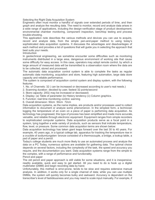
Selecting the Right Data Acquisition SystemEngineers often must monitor a handful of signals over extended periods of time, and then graph and analyze the resulting data. The need to monitor, record and analyze data arises in a wide range of applications, including the design-verification stage of product development, environmental chamber monitoring, component inspection, benchtop testing and process trouble-shooting.This application note describes the various methods and devices you can use to acquire, record and analyze data, from the simple pen-and-paper method to using today's sophisticated data acquisition systems. It discusses the advantages and disadvantages of each method and provides a list of questions that will guide you in selecting the approach that best suits your needs.IntroductionIn geotechnical engineering, we sometime encounter some difficulties such as monitoring instruments distributed in a large area, dangerous environment of working site that cause some difficulty for easy access. In this case, operators may adopt remote control, by which a large amount of measured data will be transmitted to a observation room where the data are to be collected, stored and processed.The automatic data acquisition control system is able to complete the tasks as regular automatic data monitoring, acquisition and store, featuring high automation, large data store capacity and reliable performance.The system is composed of acquisition control system and display system, with the following features:1. No. of Channels: 32 ( can be increased or decreased according to user's real needs.)2. Scanning duration: decided by user, fastest 32 points/second3. Store capacity: 20G( may be increased or decreased)4. Display: (a) Table of parameter (b) History tendency (c) Column graphics.5. Function: real time monitoring control, warning6. Overall dimension: 50cm×50cm×72cmData acquisition systems, as the name implies, are products and/or processes used to collect information to document or analyze some phenomenon. In the simplest form, a technician logging the temperature of an oven on a piece of paper is performing data acquisition. As technology has progressed, this type of process has been simplified and made more accurate, versatile, and reliable through electronic equipment. Equipment ranges from simple recorders to sophisticated computer systems. Data acquisition products serve as a focal point in a system, tying together a wide variety of products, such as sensors that indicate temperature, flow, level, or pressure. Some common data acquistion terms are shown below:Data acquisition technology has taken giant leaps forward over the last 30 to 40 years. For example, 40 years ago, in a typical college lab, apparatus for tracking the temperature rise in a crucible of sodiumtungsten- bronze consisted of a thermocouple, a bridge, a lookup table, a pad of paper and a pencil.Today's college students are much more likely to use an automated process and analyze the data on a PC Today, numerous options are available for gathering data. The optimal choice depends on several factors, including the complexity of the task, the speed and accuracy you require, and the documentation you want. Data acquisition systems range from the simple to the complex, with a range of performance and functionality.Pencil and paperThe old pencil and paper approach is still viable for some situations, and it is inexpensive, readily available, quick and easy to get started. All you need to do is hook up a digital multimeter (DMM) and begin recording data by hand.Unfortunately, this method is error-prone, tends to be slow and requires extensive manual analysis. In addition, it works only for a single channel of data; while you can use multiple DMMs, the system will quickly becomes bulky and awkward. Accuracy is dependent on the transcriber's level of fastidiousness and you may need to scale input manually. For example, ifthe DMM is not set up to handle temperature sensors, manual scaling will be required. Taking these limitations into account, this is often an acceptablemethod when you need to perform a quick experiment.Strip chart recorderModern versions of the venerable strip chart recorder allow you to capture data from several inputs. They provide a permanent paper record of the data, and because this data is in graphical format, they allow you to easily spot trends. Once set up, most recorders have sufficient internal intelligence to run unattended — without the aid of either an operator or a computer. Drawbacks include a lack of flexibility and relatively low accuracy, which is often constrained to a few percentage points. You can typically perceive only small changes in the pen plots. While recorders perform well when monitoring a few channels over a long period of time, their value can be limited. For example, they are unable to turn another device on or off. Other concerns include pen and paper maintenance, paper supply and data storage, all of which translate into paper overuse and waste. Still, recorders are fairly easy to set up and operate, and offer a permanent record of the data for quick and simple analysis.Scanning digital multimeterSome benchtop DMMs offer an optional scanning capability. A slot in the rear of the instrument accepts a scanner card that can multiplex between multiple inputs, with 8 to 10 channels of mux being fairly common. DMM accuracy and the functionality inherent in the instrument's front panel are retained. Flexibility is limited in that it is not possible to expand beyond the number of channels available in the expansion slot. An external PC usually handles data acquisition and analysis.PC plug-in cardsPC plug-in cards are single-board measurement systems that take advantage of the ISA or PCI-bus expansion slots in a PC. They often have reading rates as high as 100,000 readings per second. Counts of 8 to 16 channels are common, and acquired data is stored directly into the computer, where it can then be analyzed. Because the card is essentially part of the computer, it is easy to set up tests. PC cards also are relatively inexpensive, in part, because they rely on the host PC to provide power, the mechanical enclosure and the user interface. Data acquisition optionsIn the downside, PC plug-in cards often have only 12 bits of resolution, so you can't perceive small variations with the input signal. Furthermore, the electrical environment inside a PC tends to be noisy, with high-speed clocks and bus noise radiated throughout. Often, this electrical interference limits the accuracy of the PC plug-in card to that of a handheld DMM .These cards also measure a fairly limited range of dc voltage. T o measure other input signals, such as ac voltage, temperature or resistance, you may need some sort of external signal conditioning. Additional concerns include problematic calibration and overall system cost, especially if you need to purchase additional signal conditioning accessories or a PC to accommodate the cards. Taking that into consideration, PC plug-in cards offer an attractive approach to data acquisition if your requirements fall within the capabilities and limitations of the card.Data loggersData loggers are typically stand-alone instruments that, once they are setup, can measure, record and display data without operator or computer intervention. They can handle multiple inputs, in some instances up to 120 channels. Accuracy rivals that found in standalone bench DMMs, with performance in the 22-bit, 0.004-percent accuracy range. Some data loggers have the ability to scale measurements, check results against user-defined limits, and output signals for control.One advantage of using data loggers is their built-in signal conditioning. Most are able to directly measure a number of different inputs without the need for additional signal conditioning accessories. One channel could be monitoring a thermocouple, another a resistive temperature device (RTD) and still another could be looking at voltage. Thermocouple reference compensation for accurate temperature measurement is typicallybuilt into the multiplexer cards. A data logger's built-in intelligence helps you set up the test routine and specify the parameters of each channel. Once you have completed the setup, data loggers can run as standalone devices, much like a recorder. They store data locally in internal memory, which can accommodate 50,000 readings or more.PC connectivity makes it easy to transfer data to your computer for in-depth analysis. Most data loggers are designed for flexibility and simple configuration and operation, and many provide the option of remote site operation via battery packs or other methods. Depending on the A/D converter technique used, certain data loggers take readings at a relatively slow rate, especially compared to many PC plug-in cards. Still, reading speeds of 250 readings/second are not uncommon. Keep in mind that many of the phenomena being monitored are physical in nature —such as temperature, pressure and flow —and change at a fairly slow rate. Additionally, because of a data logger's superior measurement accuracy, multiple readings and averaging are not necessary, as they often are in PC plug-in solutions.Data acquisition front endsData acquisition front ends are often modular and are typically connected to a PC or controller. They are used in automated test applications for gathering data and for controlling and routing signals in other parts of the test setup. Front end performance can be very high, with speed and accuracy rivaling the best standalone instruments. Data acquisition front ends are implemented in a number of formats, including VXI versions, such as the Agilent E1419A multifunction measurement and control VXI module, and proprietary card cages.. Although front-end cost has been decreasing, these systems can be fairly expensive, and unless you require the high performance they provide, you may find their price to be prohibitive. On the plus side, they do offer considerable flexibility and measurement capability.Data Logger ApplicationsA good, low-cost data logger with moderate channel count (20 - 60 channels) and a relatively slow scan rate is more than sufficient for many of the applications engineers commonly face. Some key applications include:• Product characterization• Thermal profiling of electronic products• Environmental testing; env ironmental monitoring• Component characterization• Battery testing• Building and computer room monitoring• Process monitoring, evaluation and troubleshooting No single data acquisition system works for all applications. Answering the following questions may help you decide which will best meet your needs:1. Does the system match my application?What is the measurement resolution, accuracy and noise performance? How fast does it scan? What transducers and measurement functions are supported? Is it upgradeable or expandable to meet future needs? How portable is it? Can it operate as a standalone instrument?2. How much does it cost?Is software included, or is it extra? Does it require signal conditioning add-ons? What is the warranty period? How easy and inexpensive is it to calibrate?3. How easy is it to use?Can the specifications be understood? What is the user interface like? How difficult is it to reconfigure for new applications? Can data be transferred easily to new applications? Which application packages are supported?ConclusionData acquisition can range from pencil, paper and a measuring device, to a highly sophisticated system of hardware instrumentation and software analysis tools. The first step for users contemplating the purchase of a data acquisition device or system is to determine the tasks at hand and the desired output, and then select the type and scope of equipmentthat meets their criteria. All of the sophisticated equipment and analysis tools that are available are designed to help users understand the phenomena they are monitoring. The tools are merely a means to an end.正确选择数据采集系统工程师经常要对很长时间内的很多信号进行监测、画图和分析产生的数据。
描写机器人的英语作文

Robots have become an integral part of modern technology,transforming various industries and aspects of our daily lives.Heres a detailed composition on robots, exploring their evolution,applications,and potential future developments.Introduction to RobotsRobots are machines designed to execute tasks automatically,often with the ability to interact with their environment.The concept of a robot dates back to ancient times,but it was only in the20th century that they became a reality in the form we recognize today. The term robot was first coined by Czech writer KarelČapek in his1920play R.U.R. Rossums Universal Robots,which depicted artificial beings capable of performing human tasks.Evolution of RoboticsThe evolution of robots can be traced through several key milestones.Early robots were primarily industrial,designed for repetitive tasks such as assembly line work.The first programmable robot,the Unimate,was introduced in1961and revolutionized manufacturing by automating the process of die casting and spot welding.Over time,robots have become more sophisticated,with advancements in artificial intelligence AI and machine learning allowing them to perform more complex tasks. Today,robots are capable of learning from their experiences,making decisions,and even interacting with humans in a more natural way.Applications of RobotsRobots are now used in a wide range of applications across various sectors:1.Industrial Automation:Robots continue to play a crucial role in manufacturing,where they perform tasks such as precision assembly,material handling,and quality control.2.Healthcare:In the medical field,robots assist in surgeries,deliver medication,and even help in patient rehabilitation.3.Domestic Assistance:Home robots perform tasks like cleaning,lawn mowing,and even providing companionship to the elderly.4.Space Exploration:Robots explore environments that are inhospitable to humans,such as deep space or the ocean floor.5.Disaster Response:In emergency situations,robots can enter dangerous areas to assess damage,locate survivors,and assist in rescue operations.itary:Autonomous drones and ground vehicles are used for surveillance, reconnaissance,and combat support.Technological AdvancementsThe integration of AI has been a significant factor in the advancement of robotics.Robots now have enhanced sensory capabilities,allowing them to perceive their surroundings and interact with them more effectively.They can process information,make decisions based on complex algorithms,and even exhibit a level of autonomy.Ethical ConsiderationsAs robots become more advanced,ethical considerations come to the forefront.Issues such as privacy,job displacement,and the potential for misuse of technology are important to address.Ensuring that robots are designed and used responsibly is a challenge that society must face.Future of RoboticsThe future of robotics is promising,with ongoing research and development aimed at creating more intelligent,adaptable,and interactive machines.We can expect to see robots that are capable of performing tasks with greater autonomy,learning from their environment,and even exhibiting emotional intelligence.In conclusion,robots are not just a product of science fiction but a reality that is continuously evolving and expanding.As technology progresses,the role of robots in society will only grow,offering new possibilities and challenges that we must navigate with care and foresight.。
surfer8.0

Surfer 8.0IntroductionSurfer 8.0 is a powerful and user-friendly software program used for contour mapping, 3D surface mapping, and terrain modeling. It is widely used by scientists, engineers, and researchers in various fields such as geology, environmental science, and hydrology. This document provides an overview of Surfer 8.0, its features, and its applications.FeaturesSurfer 8.0 offers a wide range of features that enable users to create accurate and detailed maps and models. Some of the key features of Surfer 8.0 are:1.Contour Mapping: Surfer 8.0 allows users to create contour mapsfrom XYZ data, grid files, and various other sources. The contour lines can be customized with different colors, line styles, and labels.2.3D Surface Mapping: With Surfer 8.0, users can generate impressive3D surface maps from gridded data. The maps can be rotated, tilted, andzoomed to provide a comprehensive view of the terrain.3.Terrain Modeling: Surfer 8.0 includes advanced terrain modelingcapabilities that allow users to create accurate and detailed terrain models.Users can visualize changes in elevation, slope, and aspect using color gradients and shading.4.Data Import and Export: Surfer 8.0 supports a wide range of dataformats, including XYZ, CSV, DXF, and DEM. Users can import data fromexternal sources and export their maps and models in various file formats, such as BMP, JPEG, and PDF.5.Grid Data Analysis: Surfer 8.0 provides tools for analyzing andmanipulating grid data. Users can perform mathematical operations, applyfilters, and create grid-based calculations to derive valuable insights from their data.6.Overlay and Blend Maps: Surfer 8.0 allows users to overlay multiplemaps and blend them together to create informative and visually appealingrepresentations. This feature is particularly useful when comparing different datasets or highlighting specific features.ApplicationsSurfer 8.0 has a wide range of applications across various fields. Some of the key applications of Surfer 8.0 are:1.Geology: Surfer 8.0 is extensively used in geology for visualizinggeological features, mapping rock formations, and analyzing topographic data.It helps geologists in understanding the structure and composition of theEarth’s surface.2.Environmental Science: Surfer 8.0 plays a crucial role inenvironmental science by providing tools for analyzing and interpretingenvironmental data. It helps environmental scientists in studying land usepatterns, monitoring pollution levels, and predicting environmental impacts.3.Hydrology: Surfer 8.0 is widely used in hydrology for analyzing waterflow, delineating watersheds, and modeling flood zones. It enables hydrologists to identify potential flood areas, plan water resource management strategies, and assess the impact of environmental changes on water systems.4.Civil Engineering: Surfer 8.0 is utilized in civil engineering for siteselection, land development, and infrastructure planning. It helps civilengineers in evaluating the suitability of a site, assessing the terraincharacteristics, and optimizing the design of structures.5.Oceanography: Surfer 8.0 is employed in oceanography for mappingocean currents, analyzing bathymetry data, and studying wave patterns. Itenables oceanographers to understand the behavior of oceans, identifypotential hazards, and plan marine expeditions.ConclusionSurfer 8.0 is a powerful and versatile software program that offers a wide range of features for contour mapping, 3D surface mapping, and terrain modeling. It is widely used in various fields such as geology, environmental science, hydrology, civil engineering, and oceanography. With its user-friendly interface and advanced capabilities, Surfer 8.0 provides professionals and researchers with the tools they need to visualize and analyze spatial data effectively.。
Introducingreferencemodels
Introducing Reference Models in ERP DevelopmentSigne Ellegård BorchIT University of Copenhagen****************IntroductionBusiness process reference modelling is not a new topic in the ERP software industry: ERP vendors have used reference models for analysis and configuration of their ERP systems since the mid-nineties. Also from a research point of view, the field working with reference models and ERP systems is well established, typically addressing formal topics, such as e.g. model configuration and correctness (Recker et al. 2006).However, there is no prior research on how reference models may enter a real software engineering context. We lack empirical evidence on the actual process of introducing reference models in ERP software development. What do people do when they are involved in such a project? How do they make the reference modelling approach fit the current systems and practices of the software development organisation? The aim of my research project is to make this work visible.The motivation for this investigation is to improve the understanding of how new design ideas may enter an already existing development practice – this knowledge is relevant in the context of the current research cooperation between universities and industry, and may guide the way in which innovative ideas founded in theory are implemented in practice. Moreover, there is both a practical and theoretical relevance in understanding how reference models are made to fit the very particular situation of one ERP vendor: from a research perspective, this provides a more detailed picture of what kind of phenomenon reference modelling is, and from a practical perspective it may inspire how the ERP vendor support the process of introducing reference modelling.Research questionsMy investigation is guided by the following research questions:What is characterizing the process of introducing reference modelsand modelling tools in ERP software development?What aspects of the ERP software development are thereference models designed to support, and how are thedifferent kinds of anticipated model use negotiated?How do the people involved in model and modelling tooldesign make sense of their activity, its outcome and thedomain they are targeting?What is the connection between the model design and thealready existing systems, practices and conceptualizationswithin the ERP software development organization? Empirical studyI have been doing empirical research on the introduction of reference models in Microsoft Business Solutions (MBS) since 2004. This long-term engagement makes it possible to get a historical perspective on the process.In 2002 Microsoft acquired a number of successful ERP vendors targeting the market of small and midsized companies. The ERP vendors were grouped under the common name Microsoft Business Solutions, but still maintained their original products. Based on extensive research on the current use of their existing ERP systems, MBS formulated a vision for the future ERP development and started a project exploring these ideas. Project Green was the name of this development effort that had the objective of building a completely new ERP system (the name refers to a system developed in a “green field”, from scratch). The system was to be based on new technology, new architecture and should introduce a number of features that were not supported in the current generation of ERP products. Business process reference models played an important role in this vision, where one aim was a ”process centric application design delivered through a model-driven approach” (MBS internal white-paper).From summer 2004 until spring 2005 an interdisciplinary project group worked on how to flesh out the Green vision with regard to e.g. workflow support, user interface design, reference models and model repository. In spring 2005 the idea of a radical change of architecture and a completely new developed ERP system was exchanged by a more pragmatic approach that would gradually introduce the visions formulated in project Green into the already existing ERP products. From2005 there have been several projects working on how to integrate the reference modelling approach with the current ERP systems. The case that I am going to present here is related to one particular project team developing a modelling tool for the ERP partners based on reference models. This modelling tool is to be used for implementing one of the ERP products that MBS has on the market.The data material is collected using qualitative empirical methods such as participant observation, structured and unstructured interviews, and reading of project specific documents. The material consists of design discussions and decisions in the project group, the group’s meetings with other teams in the organization taking interest in the project, the group’s visits at the partners to gather requirements for the modeling tool, the model in different draft versions, and specifications and presentations communicating the modelling tool design project internally in the ERP development organization.The collection of data, and my interpretation of it, is guided by the principles of interpretive field studies described in (Klein and Myers 1999).Theoretically, I perceive my observations of the work in the project team as a process of sensemaking (Weick 1995). The ERP development practice is viewed from the perspective of activity theory (see e.g. Korpela et al. 2002). I use the concept of a design artefact introduced in (Bertelsen 2000) to describe the different purposes and meanings that the model and modelling tool are assigned by the project members. A design artefact is mediating design by supporting different aspects of a design activity, namely construction, cooperation, and conception (Bertelsen 2000). Especially the aspect of conception is important in the context this study, since it relates to the work of re-conceptualization caused by the introduction of a new design artefact.Currently, I am in the process of analysing my field material. Since this is ongoing work, I will not present the final result of my analysis, but rather point at some themes I have discovered so far. I structure my observations according to different areas where the modelling tool project team is engaged in sensemaking. Below, I will briefly present one of these areas: how the project team makes sense of the business domain. The other areas in my analysis that I leave out here are how the project team members make sense of the partners’ practice and of their own project.Making sense of the business domainIn context of the Green project, a business process reference model was developed internally at MBS. This model was defined on the basis of an existing supply-chain reference model, and its design process was to a high degree an effort of adopting and adapting the terminology to make it fit within an MBS context: the original model was designed to model supply-chains, not to support ERP systems development. The model was introduced to support cooperation between the different professions within ERP development (UI designers, developers, etc) by serving as a common frame of reference on the work of the users of the ERPsystem. However, building and maintaining a shared understanding of the business domain has proven to be a continuous task. Over time, the interest from different parts of the organization is influencing and changing both the goals and the structure of the model. The model is now a boundary object between different uses - it has its own history inscribed, and each project that has used the model has left its fingerprint. The members of the current modelling tool project deal with this inheritance since they reuse e.g. already existing diagrams, and in particular since some of the project members have been part of previous projects working with the reference model. They bring their good and bad, shared and individual, experiences to the current project.Concurrently with the adaptation of the supply-chain reference model, a generic model of the users of the ERP system was developed. This work was initiated in a different part of the ERP organization, and the model was made using a very different approach, namely by making ethnographic studies of the end users, and abstracting these descriptions into a model of generic users in a generic organization.The concepts of the business process reference model are partly overlapping with those of the generic user model, but even though it has been a long term wish to integrate these models, it is still ongoing work. This work is also performed in the modelling tool project.One of the big challenges for the project group is that neither ERP system nor reference model is developed from a green field. This resembles a legacy problem: The ERP system is already there, which means that the model cannot be understood as a specification of the system, and the model is already there, which means that the model cannot serve as documentation of the system. This picture gets even more complicated since the ERP system is still under development as new modules are added and new versions released. Many design discussions touch upon the question of whether the model and modelling tool should reflect only how the system is today, or whether the project team should be “pioneering” and making requests for changes to the existing ERP system. The strict division and causal relationship between model and ERP system seems to break down in the design discussions; instead they are envisioned to be in a dialectic relationship: they are co-constructed.Other problems with relating the model to the existing ERP system stem from the clash of two different design paradigms. One of the visions from the Green project was that when a reference model was introduced it would drive the change from a data-centric to a business process centric “design philosophy”. From a practical point of view, the tool project team struggles with this shift from the current data centric ERP system to a process centric paradigm. The project group experiences problems with mapping the newly introduced concepts of the model to the already existing ERP system. The existing ERP system is menu based, document and data centric, not process centric, and this causes problems: One example is that the form (a window corresponding to a paper form, where the user can view and enter data, e.g. a sales order) is the smallest conceptual component in the current systems. The problem is how to map an ERP system to a model thathas a much finer granularity (e.g. the concept of a task, as “find product number”)?Alignment of the business process reference model with its historical and current versions, the generic user model, and the existing ERP system means negotiating content, scope, structure and key concepts: what is a business process, what is a task, what is a user role?Concluding remarksThe reference model, its concepts and its purpose is in a dialectical relationship with what is already there. The process of introducing reference modelling is characterized by inertia - the changes that the model is envisioned to make is constrained by existing structures. However, through processes of sensemaking the reference model is made to fit these structures while transforming them. ReferencesBertelsen, O. W. (2000). “Design Artefacts: Toward a design-oriented epistemology”.Scandinavian Journal of Information System s, vol. 12.Fettke, P.; Loos, P. (2003). “Classification of reference models - a methodology and its application”. Information Systems and e-business Management, 1 (1).Klein, H.; Myers, M.D. (1999). “A Set of Principles for Conducting and Evaluating Interpretive Field Studies in Information Systems”. MIS Quarterly, vol. 23, No. 1.Korpela, M.; Mursu, A.; Soriyan, H. A.; (2002). ”Information Systems Developement as an Activity”. Computer Supported Cooperative Work, vol. 11, No. 1-2.Recker, J., Rosemann, M., van der Aalst, W.; Mendling, J. (2006) ”On the Syntax of Reference Model Configuration. Transforming the C-EPC into Lawful EPC Models”. In Bussler, C.;Haller, A. eds: Business Process Management Workshops, vol. 3812, LNCS, Springer, Germany, p. 497-511.Weick, K. E. (1995). “Sensemaking in Organizations”. Reading, Mass., Sage.。
- 1、下载文档前请自行甄别文档内容的完整性,平台不提供额外的编辑、内容补充、找答案等附加服务。
- 2、"仅部分预览"的文档,不可在线预览部分如存在完整性等问题,可反馈申请退款(可完整预览的文档不适用该条件!)。
- 3、如文档侵犯您的权益,请联系客服反馈,我们会尽快为您处理(人工客服工作时间:9:00-18:30)。
Modeling IT Operations to Derive Provider Accepted Management ToolsS. Abeck, C. MayerlUniversity of KarlsruheInstitute of Telematics, C&M IT ResearchZirkel 276128 KarlsruheGermanyPhone: +49-721-608-[6391|6390], Fax: +49-721-388097E-mail: [abeck|mayerl]@rmatik.uni-karlsruhe.deAbstractIn this paper a process oriented approach to derive requirements on IT management tools is presented. The starting point is given by the processes that have to be carried out to run a distributed system. The better a management tool supports these processes the more useful it is from the viewpoint of the provider. Hence, the more accepted the tool is by the operators doing their work in the IT organization. The process model describing IT operations of a distributed networked system stems from an industrial project. The project goal was to introduce a process oriented quality management system into a complex IT environment. One of the operational processes of the model, the process Operation of Changes is described in more detail which demonstrates the method to derive demands on management tools from the process description. The result of this method is a collection of tools supporting request, commitment, performance and evaluation of an IT change. The integrated software architecture and the central software modules of our solution are outlined. The method described in this paper has been successfully applied to various fields of IT management.KeywordsProcess Model, IT Operations, Networked Systems, Management, Management ToolsClassificationD: C.2.3, D.2.9, D.4.4, H.4.1, K.6.21IntroductionOperators of IT resources more and more become service providers. In this role a provider needs new concepts and management tools to provide services accordingDistributed Systems & Applicationsquality of service required by its customer. To guarantee quality of service parameters, such as availability or response time, the service provider should be able to control the complete process of IT service production. But, running computer systems and the network connecting these systems so far seemed to be an art. The most important characteristic of an art in this context means that you do not exactly know how something works since it depends on the intuition of people involved. In the past IT operations concepts rather depended on the intuition of operators. Rules gained from experience, controlled the way of how to run the computer and networking components. Most of the operation concepts were implemented by the operating systems running on the host systems. This situation has changed for the following two main reasons:•The process of downsizing led to a stronger use of decentralized systems, such as UNIX workstations or Windows-NT PCs. These operating systems do not support operation concepts in the same way host operation systems do.Additionally, running a distributed heterogeneous system is much more complex than running a centralized homogeneous system.•The overall goal of an IT service provider is no longer just to run the distributed system properly rather than to provide an IT service to its customer. A certain quality of service is demanded by the customer who in turn is willing to pay a certain price.Either integrated or isolated network and systems management tools play an important role in an operation concept for distributed networked systems. From the perspective of a provider these tools are used to support certain tasks and processes that have to be fulfilled to provide IT services. This viewpoint of IT management differs from the viewpoint of a software developer who is interested in the management tools and the way these tools are implemented. For a provider the implementation of management tools should be as transparent as possible. From his perspective a tool is nothing but an (computer-based) aid which gives as much support as possible to the staff performing the process. Therefore the central statement of investigations outlined in this paper is: To be able to build provider accepted management tools it is necessary to understand the processes of IT operations.In the past the necessity to investigate aspects of IT operations in order to build a formal foundation for a sound operating concept was recognized either by industry or by researchers [Ema94, DHR93]; first solutions have been successfully implemented [CKo97, HAW96].2Aspects of IT Operations and Existing FrameworksIT operations includes all aspects to run a given IT infrastructure and to provide a certain IT service. Therefore, basic elements that have to be investigated are:Modeling IT Operations to Derive Provider Accepted Management Tools1.IT infrastructure – hardware and software: These are the main objects ofinvestigation in computer science. In the past the central goal was to design and implement hardware components, especially processors, and software components, either system software or application software. The question of how to run these IT components, i.e. the field of IT operations, is related to the design and implementation. Additionally it contains some further aspects which have to be investigated.2.Functional support to run IT components: One of these aspects is tool supportthe area of integrated network and systems management has focused its work on [HAN98, LSS97]. The kernel of the network and systems management is the management architecture and its submodels, which build a kind of an abstract specification for integrated management platforms such as HP OpenView or NetView6000. Today a wide range of more or less useful management tools exists. They cover various functional aspects such as configuration, fault, performance, security, accounting that are prescribed by the functional submodel of the management architecture.3.Service level agreements, service management: The major goal of an ITservice provider running IT components of a networked system is to provide IT services according to a service level agreement (SLA). A SLA is a contract between the provider and its customer which describes the functionality of an IT service and quality of service guarantees mode by the provider. This aspect is covered by service management. The theoretical foundation of service management is given by the Telecommunication Management Network (TMN) framework [CKo97].4.Tasks and processes: A further aspect of IT operations to be mentionedconcerns the question of how an IT service is provided. This leads to the tasks and processes that have to be carried out by the service provider. The most complete and advanced work on that topic that might become an accepted framework in the future, is the Information Technology Infrastructure Library (ITIL, [CCT97, CCT94]).3 A Process Model for IT OperationsThe ITIL built a main basis for our model which describes the operation of a complex networked system. This model has been successfully applied to introduce a process oriented quality management system into a computing center where a staff of 250 people are running MVS host systems, UNIX and Windows NT workstations interconnected by Ethernet, FDDI and Datex-M.A rough overview of the model is given in Figure 1. The goal of the providers’ organizations is to provide services to its customers with a certain quality as described in a service level agreement. To provide IT services in turn certain tasks, such as planing, developing or training, have to be fulfilled. In what follows we focus on those services which require the operation of componentsDistributed Systems & ApplicationsFigure 1: Overview of the process structure of an IT Service Provider building the networked system (e.g. hubs, switches, hosts, workstations, PCs). Therefore in our model the task block of IT operations is divided into three operational processes. After a short description of each process the relationships between these processes are outlined.3.1Operational ProcessesThe starting point is a networked system, which has been planned and installed beforehand. Certain routine actions such as switching on, booting, monitoring the network and system components should not have negative influence on an IT service using resources of this networked system. The process of Day to Day Operation describes this kind of routine actions. In a 24 hour operation which is the normal case in professional IT environments, operation is organized in shifts. Besides the main action of monitoring the networked system, data backup and (re-) configuration of certain components are further actions of the process Day to Day Operation.During Day to Day Operation deviations such as intermediate or total failures of network or system components are remarked. If these failures cannot be solved by applying some routine actions as part of the Day to Day Operation (e.g. reset of the component) a trouble is generated. Removing this trouble is the goal of the process Operation of Troubles. Hence the trouble has to be analyzed and diagnosed. The process is structured according to certain support levels. If a trouble cannot be diagnosed and solved on one support level it is propagated to the next higher level.Evolution is a typical property of networked systems: Network and system components are exchanged or new versions of a system or application software applied in the networked system is introduced on one or more systems. If the manipulation to be executed on the networked system exceeds a certain level ofModeling IT Operations to Derive Provider Accepted Management Toolscomplexity it cannot be part of the Day to Day Operation, instead it gets part of a process Operation of Changes . This process guarantees a planned and coordinated implementation of such complex manipulations, called changes. In particular planing and coordination of changes minimize the risk that something unexpected happens (e.g. failures or negative influence on neighboured components).All three operational processes are tightly interconnected as shown by the process transitions described above and illustrated in Figure 1. It ’s not the model ’s purpose to define a routine manipulation, a trouble, or a change for a given provider organization. Table 1 gives an example how a concrete provider might differentiate between these three terms.A precise assignment of situations occurring during IT operations to one of the operational processes is important since this defines the way the situation has be handled by the operational staff. The more complex routine manipulations areTable 1: Examples for operational situationsPart of theDistr.SystemRoutine Trouble ChangeNetwork Reset of a networkcomponent Failure of a network component, that cannot be handled by a routine manipulation Introduction of a new network component Switching a backuplineLoss of a connection Adding Backup lines to the network Regular change offansExchange of a defect network component Introduction of a new network technology (e.g. ATM)System New entry of a userUser has no access Change of security relevant user rights Reset of a systemTotal or partial failure Exchange of a defect system Regular backupFailure during the backup procedure Introduction of a new backup system Application New entry of a userto have access to theapplicationUser has no access to the application Introduction of a new application or application version Reconfiguration ofI/O channels of theapplication Mass configuration with strong impactsDistributed Systems & Applicationsallowed to be executed during the Day to Day Operation, the less transitions to the Operation of Troubles and the Operation of Changes will take place. This implies that the provider runs a higher risk since routine manipulations are less planned and less coordinated than changes are.4Deriving Demands on Management Tools from the Process ModelA detailed description of the processes is useful to analyze and prescribe the way a provider organization should run the networked system. This is a prerequisite to introduce a quality management system. We use the process description for another important and demanding purpose: we investigate what kind of (tool) support a provider demands in a way that a process can be executed as efficiently as possible. This leads to process oriented requirements on management tools and hence to provider accepted tool implementations as we will illustrate with the following example of the process Operation of Changes [AMa97].4.1 The Process Operation of ChangesMany aspects that have to be covered by this process can be found in a management functional area. In literature it is referred to as Change Management [CCT94]. We have chosen the name Operation of Changes to stress that this process describes not only the management, i.e. monitoring and controlling but also the operation, i.e. executing the change on certain network or system components of the distributed networked system [DSW98].The process can be subdivided into four phases: After a Request Phase where a change request (CR) is expressed, the CR has to be accepted and planned in a Commitment Phase. If the planning has been finished successfully, the change is executed in a phase that in literature is called Performance Phase [Sch96]. The process is concluded by an Evaluation Phase where experiences from the former phases are documented in a kind of change knowledge base.In the following actions to be fulfilled by the staff in each phase of the process are investigated. As outlined in Figure 2, the goal is to derive P rocess o riented M anagement means (PoMs) to perform each action effectively and efficiently. A good and pragmatic understanding of each action and hence of IT operations is a prerequisite to define PoMs.One of the first actions to be taken in the process Operation of Changes is to specify the change request. Therefore a specific PoM, which we call a change order form is needed to carry out this action of the process. The change order form is an information structure used to record the information that the initiator of a request for change has to fill in.Modeling IT Operations to Derive Provider Accepted Management ToolsThis includes• identity of the initiator (name, telephone, e-mail)• reason for the change request • network and system components involved • temporal aspects (e.g. deadlines, frozen zones)Such a PoM change order form can be designed adequately only if we understand how it should be used in the overall process. We have analyzed how different network and system providers use such change order forms. In most cases these forms do only exist on paper, i.e. there is no computer-based solution for this PoM. Major demands of IT providers on a management tool implementing a change order form are:• Flexible definition of the form structure: There are different types of changes which require different information fields on the form. Therefore, the form has to be customizable.• Easy fill-in: Initiators and recipients of the form should be able to use text editors they are used to.• Electronic transfer: Existing transfer mechanisms, such as WWW, e-mail, ftp or fax have to be supported.•Check functions: Completeness and consistency are to be checked.en ta tio n b a sed o n m a n a g em en t to o lsFigure 2: Overview of the taken approachDistributed Systems & ApplicationsThe next action has to classify the requested changes. The aim of this action is to schedule all requests during a certain time period e.g. a whole year. There are three main classes of changes [CCT94]:•Urgent changes have the highest priority to be executed. The origin of an urgent change often is a great problem in the networked system which endangers the service level agreements with the users.•Normal changes have to be queued considering deadlines and available resources in men and materials.•Impracticable changes cannot be executed because there are no resources or no enabling technology.The classification results in a queued list of accepted change requests which have to be done.An aid supporting the classification and queuing of changes is the change schedule. It allows the provider to get a clear overview of all changes to be done during a certain time frame, e.g. one year. The change schedule considers the provider’s resources and contains deadlines for each change. It also supports global execution control of each change. If a new urgent change is requested or if the deadline of an important change is endangered the change schedule could be adapted.A PoM associated with a change schedule is the task schedule of each change. This aid contains all tasks that are required to execute a particular change. It also plans the responsibility and the employment of each task and underlines risks. Major demands on a management tool implementing change schedule and task schedule are:•Getting an overview of all changes for a period of time e.g. for one year considering deadlines and resources in manpower and materials.•Planning all tasks of an particular change considering responsibilities and risks.•Controlling the execution of each change, verifying milestones and deadlines.Because we say a change is a special kind of project, we can evaluate project management tools to plan and control changes.The more knowledge a provider has about changes the faster and more exactly a task schedule can be produced. Therefore another PoM is the change knowledge base, which contains the history of all executed changes in terms of documented problems and risks. The experience from a post similar change (that is gathered in the change knowledge base) could speed up the planning of the current change. A management tool implementing the change knowledge base has to support•the documentation of the current execution of a change underlining occurred problems,•the effective and efficient investigation of the history of documented changes.Modeling IT Operations to Derive Provider Accepted Management Tools The list of actions and PoMs of the process Operation of Changes given above are examples. It has to be customized by each provider depending on the concrete scenario of a networked system. Also an evolution of the process Operation of Changes could cause the creation or destruction of actions and the PoMs involved.A provider accepted management tool set has to take into account these requirements. We can implement such a solution by integrating existing management tools in a certain kind of platform which incorporates a mixture of workflow and groupware concepts. A concrete implementation is described in the next section.4.2Resulting provider accepted tool: Cooperative IT Change Control The investigation of the process Operation of Changes and the PoMs lead to a provider accepted tool set to support the execution of changes. The demands influence the architecture of this tool set named C ooperative I T C hange C ontrol (CICC) [AMa97]. Figure 3 shows an overview of the architecture of CICC.The better the management tools support the process the more useful they are from the viewpoint of the provider and hence, the more the IT provider is accepting these tools. Therefore the aim is to integrate the management tools into the process. This could be realized by a process oriented management platform shown in Figure 3. This platform and tool environment support the following functions:Figure 3: Integrated Management PlatformDistributed Systems & Applications•The communication and cooperation functions provide the fundamental mechanisms of a distributed application environment to manage a networked system. The platform contains the technical mechanisms to transport information. This information is necessary to manage the networked system and to support the cooperation of remote roles. Therefore there are two kinds of communication directions: The first one is a vertical communication between the application modules involved as PoMs in the process and the networked system. This communication direction is often supported by management tools or mechanisms like network and systems management protocols enabling an application to monitor (and control) the networked system. Examples for such protocols are the simple network management protocol (SNMP) and the common management information protocol (CMIP).The second kind of communication mechanisms supports the horizontal communication and cooperation between roles using the distributed management application modules. These communication mechanisms (as for example email, www, ftp or even middleware like CORBA) use the networked system only as a transport medium. The platform allows to integrate tools into CICC using these communication mechanisms.•Considering the process oriented approach the platform supports functions to guide the provider roles executing the process. This leads to what we call assistant functions. These functions provide a role oriented view on the operational process (in this case the Operation of Changes) and support the role to execute the necessary tasks efficiently. The desktop of an assistant consists of a list of scheduled tasks, a role specific overview of the process Operation of Changes and task specific forms to interact with the role. It is also possible to handle exceptions using other management tools. This flexibility is realized by the Guided Cooperation Concept (GCC).•Coordination functions provide the assistant functions described before and coordinate the (technical) communication and cooperation between the management tools. They schedule the tasks to be executed and dispatch the tasks to the responsible roles. Typical examples of coordination functions are calendar and agent functions. Additionally there are functions to trigger an automated action if this is predefined.•Other functions are the guideline configuration to define and customize guidelines describing the process and a guideline repository to gather the guidelines of a special provider. These functions help to configure the management tool environment CICC depending on the IT scenario. A history function which logs the current state of the process, supports the learning process: the logging data protocols the executed changes; these experiences could be used for further changes and help to adapt and improve the configuration of the process guidelines [WWT98].•The management application tools or modules specified as PoMs are integrated in the process oriented management platform. Examples ofModeling IT Operations to Derive Provider Accepted Management Toolsmanagement applications are tools to monitor and control the networked system. These tools are known by the network and systems management and often are parts of integrated network and systems platforms like HP Openview, Cabletron Spectrum and Tivoli TME. Other important management tools supporting the process Operation of Changes are a database containing the service level agreements which have to be fulfilled by the process Operation of Changes, a planner to consider the operational tasks and the distribution of human resources. A management tool describing the current configuration of the networked system is necessary to execute the Operation of Changes. This tool is the implementation of the PoM configuration documentation. To support decisions, reporting tools evaluate and correlate management relevant informations and present the results as statistics. These management applications are only examples. The list of tools has to be customized depending on the concrete scenario.To be effective and efficient in fulfilling the service level agreements in the process Operation of Changes it is necessary to integrate the management tools into the process. The process oriented management platform supports this kind of tool based integration.4.3Implementation experiencesThe realization of a provider accepted management tool environment, like CICC, could be done in different ways. Investigations of providers have shown that the main criterion to differentiate realizations from each other is how to integrate the management tools into the process. The result is a migration from paper based to tool based process oriented management platforms. The following steps show a possible migration way when realizing such a management platform. Each step leads to a tool environment implementing a special issue of the tool integration. 1. A prerequisite for managing the networked system effectively and efficiently isthe transparency of the operational processes (such as Operation of Changes).The description of the processes specifies how to run the networked system.Often there are paper based quality handbooks which are the result of undertaken certification projects [ISO9000]. These handbooks [IZ97, SCZ97] describe the processes and activities and refer to forms and management tools which have to be used. What obviously misses in most approaches, is the technical integration of management tools into the process. Projects in collaboration with industry have shown that the acceptance of quality handbooks is not very high among employees because of overwhelming maintenance and implementation in details. The experience shows that the knowledge about the process (e.g. Operation of Changes) must become closer to the usage of management tools to accept the process guidelines as an advantage.Distributed Systems & Applications2.The next step is to migrate the paper based handbook to a tool based processdescription. Because of intuitive usage web technologies are intensivelypropagated [ABMH98]. An important advantage is the efficient maintenanceof the process information offered by a web server. Special web technologieslike Active Server Pages (ASP) [Mic96] also allow to integrate managementtools into the process description. In this case the web technology is theprocess oriented management platform shown in Figure 3. The guidelines aredefined and implemented by e.g. HTML-editors and can be enriched by figuresand multimedia features like conference systems etc.A web based prototype of CICC shows possible implementations of PoMsconsidering the demands of the provider: The change order form [Pet97] inthis case is realized by a JAVA applet. This allows the initiator role to activatethe applet inside a web browser. The usage of web browsers is intuitive andwell understood today. It is also possible to integrate audio and video functionshelping the user to fill in the change order form. Therefore, the appletrepresents a form which explains what kind of information has to be filled in.The applet in turn writes this information into a database connected to theWWW. Another module of CICC is the classifier which supports the providerto evaluate the requested changes. This application retrieves the requests fromthe database and displays them to the change manager. Another filling formsupports the possibility to schedule the requests with priorities and deadlines.The classifier is also implemented in JAVA and can be activated in a webbrowser.3.Keeping the advantages of web technologies we are working on a next step ofa process oriented management platform. The main functions of the platformsupport the communication and cooperation between the roles executing theprocesses and management tools that are used. A preferred technologyimplementing such distributed application environments is the CommonRequest Broker Architecture (CORBA) of the Object Management Group(OMG). This middleware offers the necessary flexibility to integrate (legacy)management tools depending on the provider processes. In order to implementthe coordination functions the CORBA platform has to be expanded. Offeringassistant functions the web browser is used as front end because of its intuitiveuse.5ConclusionThe evolution of IT operators towards IT service providers is going on. Thereforethe need to support processes providing the IT services will increase. Theapproach outlined in this paper has not only been applied to the field of ITchanges. Two further successful projects which should be mentioned are:•Design and implementation of a management solution to determine the network and system availability of a distributed system used in a largeenterprise [HAW96].。