MRSE-3-6CSKXRA中文资料
SH366006 标准版用户手册_V1.0
E36-3C90-E100中文资料(ferroxcube)中文数据手册「EasyDatasheet - 矽搜」
核心组功率条件下属性
B( MT)在
GRADE 3C90
H = 250 A /米 ; F = 25千赫 ; T = 100 °C
330
µe 61 97 152 191 243 382 1610
F = 25千赫 ; Bˆ = 200 mT; T = 100 °C
1.4
Dimensionsin mm.
图1 E36/21/12核心一半.
E36/21/12
VALUE 0.762 12160 96 126 121
31
UNIT mm 1 mm 3 mm mm 2 mm 2 g
handbook, halfpage handbook, halfpage
36 ±0.7 +1.2
24.5 0 10.2 0 0.5
+0.6
15.75
0 21.75
飞磁
E型磁芯及配件
E36/21/12
数据表状态定义
数据表 状态
初稿 规范
产品规格
产品 状态
发育
生产
定义
此数据表包含初稿数据.飞磁防护留在任何时间更改,恕不另行通知,以 提高设计和提供最好产品权利.
此数据表包含最终规格.飞磁防护留在任何时间更改,恕不另行通知,以提 高设计和提供最好产品权利.
免责声明
生命支持应用
L 测量,40
±20 N.
铁心损耗( W)在
F = 100千赫 ; Bˆ = 00 mT;
T = 100 °C
F = 100千赫 ; Bˆ = 200 mT;
T = 25 °C
1.5
F = 100千赫 ; Bˆ = 200 mT;
T = 100 °C
前线安全UltraRAE 3000+复合物特异性监测仪产品介绍说明书

Company Reg No: SC260789 VAT Reg No: GB 828 8779 58t:+44(0)141 771 7749e:*************************.ukUnit F, 230 Parkway Point, Springhill Parkway,D A T A S HE E TThe UltraRAE 3000+ is one of the most advanced Compound-Specific Monitors on the market. Its Photoionization Detector’s (PID) extended range of 0.01 to 10,000 ppm in VOC mode and 10 ppb to 200 ppm inbenzene-specific mode makes it an ideal instrument for applications,from entry pre-screening during refineryand plant maintenance to hazardousmaterial response, marine spill response and refinery down-stream monitoring.•Dual detection mode for total benzeneexposure assessment: 60-second snapshot or 15-minute STEL measurement•High sensitivity to benzene provides a lower detection range for future benzene exposure limits •Lower risk of false alarms through advanced speciation method•Total VOC measurement mode with extended range of 0.01 to 10,000 ppm•Versatile VOC or Benzene-Specific modes•Cost effective solution and low-cost RAE-Sep TM tubes •Reflex PID Technology TM•Highly specific readings, combining a 9.8eV UV lamp and RAE-Sep™ benzene tube•Built-in humidity sensor with Automatic temperature-controlled sampling time calculation•See-through Sampling probe design for instant tube-breakthrough visibility•Highly connectivity capability through multiple wireless module options•Multi-language support•Easy access to lamp, sensor and battery in seconds without tools•Confined space entry pre-screening during refinery and plant maintenance•Hazardous material response •Marine spill response•Refinery down-stream monitoring •Plant overhaulF E AT U R E S & B E NE F I T SA PPLIC AT IO N SWorkers can easily and quickly obtain VOC readings anywhere in the facility with the RAE Systems UltraRAE 3000+UltraRAE 3000+Portable Handheld Compound-Specific VOC MonitorMONITOR ONLY INCLUDES:•UltraRAE 3000+ Monitor, Model PGM-7360•Wireless communication module built-in •Travel Charger•RAE UV lamp and RAE-Sep™ Tubes •Flex-I-Probe™ and short probe •External filter •Red rubber boot•Alkaline battery adapter •Lamp-cleaning kit •Tool kit•Lithium-ion (Li-Ion) battery with universal AC/DCcharger and international plug kit •Soft leather carrying caseMONITOR WITH ACCESSORIES KIT:•Hard transport case with pre-cut foam padding •Charging/download cradle•5 porous metal filters and O-rings •Organic vapor zeroing kit•Gas outlet port adapter and tubing OPTIONAL CALIBRATION KIT ADDS:•Calibration gas, 34L, as specified•Calibration regulator and flow controller OPTIONAL GUARANTEEDCOST-OF-OWNERSHIP PROGRAM:•4-year repair and replacement warranty •Annual maintenance service1Contact RAE Systems for country-specific wireless approvals and certificates. Specifications are subject to change.For more information Europe, Middle East, AfricaLife Safety Distribution GmbHTel: 00800 333 222 44 (Freephone number)Tel: +41 44 943 4380 (Alternative number)Middle East Tel: +971 4 450 5800 (Fixed Gas Detection) **************************AmericasHoneywell Analytics Distribution Inc.Tel: +1 847 955 8200Toll free: +1 800 538 0363***********************Honeywell RAE Systems Phone: +1 408 952 8200Toll Free: +1 888 723 4800Asia PacificHoneywell Analytics Asia Pacific Tel: +82 (0) 2 6909 0300India Tel: +91 124 4752700China Tel: +86 10 5885 8788-3000**************************Technical ServicesEMEA:**********************US:***************************AP:***************************Datasheet_UltraRAE 3000_+_DS-1018-_EN ©2019 Honeywell International Inc.Thank you for reading this data sheet. Please notet:e:*************************.uk。
CVS塑壳断路器

德电气从一个优秀的产品和设备供应商逐步成长为整体解决方案提供商。今年,施耐德电气首次
集成其在建筑楼宇、IT、安防、电力及工业过程和设备等五大领域的专业技术和经验,将其高质
量的产品和解决方案融合在一个统一的架构下,通过标准的界面为各行业客户提供一个开放、透
明、节能、高效的 营成本。
能效管理平台,为企业客户节省高达30%的投资成本和运
3, 4 b b b b b b b
CVS630
3.4 b b b b b b b
100 690 6 440
E
50 25 20
17kA b A 13000 8000 4000
100
160
250
400
630
690
690
690
690
690
8
8
8
8
8
440Leabharlann 440440440
440
BF NHBF NHBF NHF NHF NH
施耐德电气在中国
1987年,施耐德电气在天津成立第一家合资工厂梅兰日兰,将断路器技术带到中国,取代传统保 险丝,使得中国用户用电安全性大为增强,并为断路器标准的建立作出了卓越的贡献。90年代 初,施耐德电气旗下品牌奇胜率先将开关面板带入中国,结束了中国使用灯绳开关的时代。
施耐德电气的高额投资有力地支持了中国的经济建设,并为中国客户提供了先进的产品支持和完 善的技术服务,中低压电器、变频器、接触器等工业产品大量运用在中国国内的经济建设中,促 进了中国工业化的进程。
Q 断路器应在正常环境和运行温度条件下长期工作。也可在环境温度-35 °C至-25 °C 之间正常工作。
Q 储存温度为-50°C至85°C。
Pacific Power Source ASX系列高密度AC测试单相和三相切换AC电源说明书
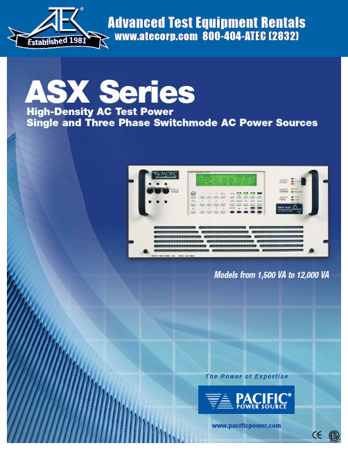
ASX SeriesHigh-Density AC T est PowerSingle and Three Phase Switchmode AC Power SourcesT h e P o w e r o f E x p e r t i s eModels from 1,500 VA to 12,000 VAAdvanced Test Equipment Rentals 800-404-ATEC (2832)E s t a b l i s h e d 1981ASX Series AC Power SourcesThe ASX Series is Pacific Power Source’s family of High Performance AC Power Sources ranging from 1.5kVA to 12kVA. Power conversion within the ASX Series is achieved by high frequency pulse width modulation, resulting in cool, quiet, andefficient operation.ApplicationsAC Test PowerThe ASX Series Power Source is equipped with a powerful microcontroller to create a fully integrated test system. It supplies a variety of power conditions to the device under test and meters/analyzes all output performance parameters.Frequency/Voltage ConversionThe ASX Series is an excellent source of stable AC voltage over the frequency range of 15 to 1,200 Hz. The output frequency is quartz-crystal stabilized. Output voltages up to 600 VAC are provided.Phase ConversionWith the ability to provide single and three-phase outputs, the ASX Series is the perfect choice to provide 1 Phase to 3 Phase or 3 Phase to 1 Phase conversion.Standard Features of each system include:• 22 Waveform Library – Arbitrary Waveform Generator.• 15 to 1,200 Hz Operation – 5,000 Hz Bandwidth.• Precision Voltage Programming – 0.05% with Continuous Self-Calibration (CSC) engaged.• Precision True-RMS metering of volts, amps, and power for displays and reporting.• RS-232 Interface with SCPI.• 1 Phase/3 Phase Switch Selectable Output from front panel or bus command.• 99 stored programs for both static and dynamic Transient Testing.Available options of each system include:• GPIB (IEEE-488.2) Interface with SCPI.• Programmable Output Impedance.• Harmonic Analysis (FFT) and Waveform Synthesis.• Load Surge Analysis and Waveform Capture.• LabView for Windows™and LabWindows™Instrument Drivers.• UPC Manager Compiled Software Suite.• Wide range of Output Magnetics for world-wide testing.Other controllers are available for applications where the ASX Serieswould be used as a manually controlled laboratory instrument, or afixed parameter OEM frequency converter.Controller Selection GuideFour controller models are available with the ASX-Series. They include 1 Phase and 3 Phase models for both manual and programmable control.• UPC-1M 1 Phase Manual Control15 Hz to 1,200 Hz.• UPC-3M 3 Phase Manual Control15 Hz to 1,200 Hz.• UPC-1 1 Phase Programmable Control15 Hz to 1,200 Hz.• UPC-3 3 Phase Programmable Control15 Hz to 1,200 Hz.All controllers provide manual operation from the front panel. Programmable Controllers may be programmed from the front panel or from a remote interface. RS-232 Interface is standard. IEEE-488 interface is optional. Programmable Output Impedance (optional)This feature creates positive, negative, or zero output impedance (Z0).• Compensates for line distribution or transformer losses.• Simulates a soft power line for product testing.Compensation range is ±10% of the output voltage.Transient GenerationTime Based TransientsCreate and execute transients that occur over a specified time segment to modify the output waveform, voltage, and frequency for any or all phases. An output trigger is provided for synchronizing external test equipment to the actual transient event.Cycle Based TransientsCreate and execute transients that substitute a waveform in any or all phases for 1 to 100 cycles. The waveform being substituted can be selected and/or modified from the waveform library.Arbitrary Waveform Generation and AnalysisWaveform EditA full-featured editor permits modification of a stored waveform in both time and frequency domains. This method can be used to quickly create spikes, dropouts, notches and other sub-cycle wave conditions. The resulting modified waveform is stored for execution in steady-state or transient programs.Waveform LibraryUp to 22 different waveforms can be stored in the waveform library for execution as part of a steady state program or for substitution in any output phase as part of a transient test program. Memory location #1 is a noneditable high resolution sine wave. Locations 2-22 are editable and can be substituted in anyoutput phase.Waveform Harmonic Synthesis (optional)Quickly create virtually any AC test waveform by building it out of harmonics. The process is as simple as keying in the magnitude and phase angle of each desired harmonic up through the 51ST. Additionally, waveforms can be created by downloading from a host PC.Waveform Analysis (optional)Provides both graphic (using LabView for Windows™) and numeric displays of the harmonic structure of a voltage or current waveform. Each waveform is analyzed for its harmonic content, up to the 51ST harmonic. Amplitude and phase are reported to the local display. UPC Manager displays numeric values as wellas a graphic summary of the harmonic spectrum.Oscillograph of voltage and currentwaveform at load due todistribution losses. THD=6.6%Same conditions as above withprogrammable Zºengaged.THD=0.25%THD=8.7%THD=22.2%THD=18.1%WAVEFORM EDITWAVEFORM SYNTHESISHARMONIC CONTENT OF METERED WAVEFORMTIME BASED TRANSIENTSCYCLE BASED TRANSIENTSEDIT WAVEFORM: NUMBER=16RANGE=2-16STARTING PHASE ANGLE=0 0-359.5°ENDING PHASE ANGLE=0 0-359.5°VOLTAGE IN PERCENT=-100 (+/-)0-100%WAVEFORM SYNTHESIS: WAVEFORM #2HARMONIC:2nd3rd4th5th6th CONTENT:.1%0%0%0%0%ØANGLE:0°0°0°0°0°V/I METER: ENTRY: 120.0FREQ=60.00 Va=120.0Vb=120.0Vc=120.0 SENSE=INT Vab=208.0Vbc=208.0Vca=208.0 MANUAL MODE Ia=06.00Ib=06.22Ic=06.15POWER METER: PHASE A PHASE B PHASE C KVA0.7200.7460.738 KW0.7200.7460.738 PF 1.000 1.000 1.000AMPS METER: PHASE A PHASE B PHASE CRMS0.7200.7460.738PEAK 1.044 1.119 1.383CREST FACTOR 1.45 1.50 1.90SETUP: PRESS 1 FOR PROGRAM SETUP2 FOR WAVEFORM SETUP3 FOR GENERAL SETUP4 FOR CALIBRATION MENU ØA CURRENT THD=17.8 % OHD=17.8EHD=0.3% HARMONIC:2nd3rd4th5th6th CONTENT:.1%17.8%0%0%0%ØANGLE:0°0°0°0°0°WAVEFORM SYNTHESIS: WAVEFORM #2 HARMONIC:2nd3rd4th5th6th CONTENT:.1%0%0%0%0%ØANGLE:0°0°0°0°0°EDIT WAVEFORM: NUMBER=16RANGE=2-16 STARTING PHASE ANGLE=00-359.5°ENDING PHASE ANGLE=00-359.5°VOLTAGE IN PERCENT=-100(+/-)0-100%Metering Waveform Control/Analysis Function KeyProvides Access to Special FunctionsProgram Setup• Copy a program.• Delete a program.• Erase all memory, reset CPU. Waveform Setup• Edit a waveform.• Copy a waveform.• Waveform synthesis.General Setup• UPC setup.• LCD setup.• UPC status.• Power source status.• Range control.• Slew rate setup.Calibration Menu• Execute externally referenced calibration.• View calibration constants.• Current Protect Opens power source output when operatordefined limits are exceeded.• Sense Establishes either local or remote sense for metering and CSC.• CSC Continuous self calibration – provides for exceptionalvoltage accuracy.• Program Z°Programmable output impedance dynamicallycompensates for output transformer or line distributionlosses. Can simulate a soft power grid.• Transition Time Permits control of the transition time whenchanging the output voltage and frequency.• Frequency Limits Sets min and max programmable frequency limits.• Voltage Limits Sets min and max programmable voltage limits.• Initial Voltage Sets power on voltage as zero volts or last executed.• Keyboard Lock Enable/disable front panel controls.Special Functions AccessedThrough UPC Setup Menu• Soft green backlight.• Adjustable.Informative 160Character LCD DisplayTotal Control, Metering, and Analysis of AC Power. Simple, Intuitive Operation.Select phase voltages and operating frequency when manual control is desired. The selected parameter is indicated by the LCD display. The clear key erases entries and keeps erasing with repeated pressing until the basic V/I screen is displayed.Parameter Select KeysExecute KeyInstantly executes a stored program that has been selected with the program key.Slew KeysSmoothly changethe designated voltage or frequency parameters.Rates are separately programmable.Transient (Trans) KeyTurns time based or cycle based transients On or Off. Indicator is On when transient is executed.Output Enable KeyTurns the output contactor of the power source On or Off. Indicator is On when the contactor is closed.Enter KeyStores new parameter data that has been keyed in.Program KeySelects 1 of 99 programs for edit or execution.Edit KeySelects the program edit mode and prompts for new entry.Store KeyStores a program upon completion of editing.Display KeySequences through each metering screen:• V/I Meter.• Power Meter.• AMPS Meter.• Waveform Analysis (option).ASX Series – Power SourcesNotes:1. Rated output power is based on a combination of output voltage, current and load power factor. Values stated represent the maximum capabilities of a given model. Consult factory for assistance in determining specific unit capabilities as they might apply to your application.2. All single phase output units (Model 115 ASX excepted) are operable with dual voltage ranges as listed. Three phase units are operable as single phase with dual voltage range capability or as three phase. Output voltage ranges and 1Ø/3Ø conversions are selected by front panel or bus commands.3. Output voltage ranges listed are for standard units. VMAX is output voltage with nominal input and full rated load applied. Other voltage ranges are available with the output magnetics options below.4. Peak Repetitive Pulse Current.5. Single phase input: 100, 110, 120, 208, 220, 230 and 240 VAC ±10%. Three phase input: 208, 220, 240, 380 and 416 VAC ± 10%. (480 V input and 400 Hz input are each available as a cost option.)6. Available current will vary with output voltage and power factor.Power Source Specifications(V out > 25% F.S.)Output Frequency 15 to 1,200 Hz. Full Power.Line Regulation 0.1% max for a ±10% line change.Load Regulation0.25% 15 to 400 Hz.(Typ. 3 phase direct coupled)0.50% 400 to 1,200 Hz.Improves to less than 0.1% with external sense and CSC enabled.Output Distortion 0.25% THD AVG 15 to 200 Hz.0.50% THD AVG 200 to 1,200 Hz.Ripple and Noise –66 dBResponse Time60 microseconds typical, 10–90%load step.All models are designed for operation in 19-inch equipment racks. Models 4 kVA and higher have side handles for ease of handling.Mounting Standard 19-inch rack. Slide railsare available as an option for all models.Height See model table above for panel height.Depth Approximately 24-inch, from the front panel to the rear of the chassis.CoolingFront or side forced air intake with rearexhaust. Automatic Fan Speed Control for low acoustic noise and extended fan life.ASX Series Power Sources can be equipped with output transformers to provide an alternate output voltage range. Selection of direct or transformer coupled range is performed by the controller via front panel or bus command. The standard frequency range for transformer coupled outputs is 45 to 1,200 Hz. Standard output ratios are 1.5:1, 2.0:1, and 2.5:1. Transformer outputs are supplied internally or externally via a Magnetics Module as listed in the above table. Consult the factory for additional information regarding special output ranges not listed above.Mechanical SpecificationsDual Range Output Magnetics OptionsMODELRATED P0WER (VA)OUTPUT FORM (Note 2)OUTPUT VOLTS MAX (Note 3)(V RMS )OUTPUT AMPS MAX (Note 6)(A RMS )OUTPUTAMPS (Note 4)(A PK )OUTPUT MAGNETICS INPUT POWER FORM (Note 5)PANEL HEIGHT (IN. + U)WEIGHT (LBS.)115ASX 1,5001Ø1321635INT.1Ø47 to 63 Hz 5¼-3U65120ASX 2,0001Ø150/30020/1490/45N/A 1Ø47 to 63 Hz 5¼-3U 75140ASX 4,0001Ø135/27032/1690/45EXT.3Ø47 to 63 Hz 8¾-5U 120315ASX 1,5001Ø3Ø132/264132 V L-N 12/64/Ø69/2323/ØINT.1Ø47 to 63 Hz 5¼-3U 75320ASX 2,0001Ø3Ø150/300150 V L-N 20/127/Ø69/2323/ØN/A 1Ø47 to 63 Hz 5¼-3U 85345ASX 4,5001Ø3Ø135/270135 V L-N 36/1212/Ø100/4040/ØEXT.3Ø47 to 63 Hz 8¾-5U 145360ASX 6,0001Ø3Ø132/264132 V L-N 48/1616/Ø120/4545/ØEXT.3Ø47 to 63 Hz 8¾-5U 1453120ASX 12,0001Ø3Ø135/270135 V L-N96/4832/Ø300/100100/ØEXT.3Ø47 to 63 Hz15¾-9U 215UPC Series Controller SpecificationsThe standard UPC Controllers offered with the ASX-Series Power Sources are the UPC-1M, UPC-3M, UPC-1, and UPC-3. The UPC Controller is a modular component of the ASX Series and is available in four configurations ranging from 1 Phase to 3 Phase and Manual Control to Programmable Control. The table below lists each model according to key features.All UPC Controllers include precise metering functions with data displayed via a 160 character LCD display. This, along with the 30-key front panel, provides the industry’s most powerful and user-friendly controller.The UPC-1 and UPC-3 controllers are available with either the RS-232 or GPIB remote interface. Commands are structured in accordance with SCPI (Standard Commands for Programmable Instruments). The RS-232 serial port operates up to 38.4 Bps. The GPIB interface is compatible with the IEEE-488.2.Range 15 to 1,200 Hz.Resolution 4 significant digits, e.g. 50.00, 400.0, etc.Accuracy±0.01%, 15 to 1,200 Hz.Range 0 to V MAX in 0.1 VAC steps.AccuracyExecutive voltage is within ±50 mVAC(0.05%) of command voltage referenced to the internal voltmeter with CSC engaged.Dynamic output impedance (Z o ) is programmable, ± Z o, MAX in 0.1% steps.Z o value in milliohms and range varies with the different models but usually results in a ±10% change in output voltage at maximum rated load current.(Optional on UPC-1, UPC-3).Phase Separation of Phases B and C are programmable 0° to 360° relative to phase A on the UPC-3 controller. Phase separation is fixed at 120° and 240°, respectively, on the UPC-3M controller.Programmable Current Limit is provided on the UPC-1 and the UPC-3controllers. Programmable range is from 0 to I PEAK , MAX of the power source.Accuracy is ±3.0%, F.S.Resolution is ±0.05%.The UPC-1 and UPC-3 controllers contain waveform libraries which store22 executable waveforms in Non-Volatile RAM. Waveforms are editable via the front panel or bus command.Provides waveform creation by entering the magnitude (% of fundamental)and phase angle for the 2ND through the 51ST harmonics. (optional UPC-1and UPC-3).Reports voltage and waveform harmonic content as a percentage of the fundamental and phase angle for the 2ND through the 51ST harmonics.Harmonic distortion (THD, EHD, and OHD) displayed in percentage. (optional on the UPC-1 and UPC-3).The Output Voltmeter is true RMS reading and each phase is measured independently. Line to neutral and line to line voltages are displayed.Range 0–354 VAC L-N,0–708 VAC L-L .Resolution0.1 VAC to front panel, 0.001 VAC to remote interface.Accuracy±0.2% of range + cal. ref.Output Ammeter is true RMS reading and each phase is measured independently. RMS and peak currents along with crest factor are displayed.Range 300% of system current rating.Resolution 0.01 A AC to front panel, 0.001 A AC to remote interface.Accuracy±0.2% of range + cal ref.Measures True Power (kW), Apparent Power (kVA) and power factor.Range Based on ammeter.Resolution1.0 watts or VA to front panel.1.0 watts or VA to remote interface.Calculated and displayed to three significant digits.Calculated and displayed to three significant digits.Each phase is algebraically summed with UPC waveform and amplified 25× to the direct coupled output.±10 VDC input for each phase modulates the output voltage ±100%.TTL signals are provided to synchronize external test equipment to the power source output.1.Zero Crossing, Phase A.2.Transient Pedestal –gate signal which is true during the entire trasient event.3.DRM –High-speed clock that is a multiple of the fundamental output f requency used to synchronize sub-cycle events.Frequency Voltage Programmable Output ImpedancePhase AngleProgrammable Current LimitWaveform LibraryWaveform Synthesis Waveform AnalysisVoltmeterAmmeterPower Power FactorCrest FactorExternal Inputs Am InputsSync Outputs1. CSC refers to Continuous Self Calibration.CONTROLLER MODEL OUTPUT MODES WAVEFORM LIBRARY TRANSIENT FUNCTIONS PROGRAM LIBRARY PROG.I LIMIT PHASE ANGLECSC (1)REMOTE INTERFACEWAVEFORM SYNTHESIS/ANALYSISPROG.OUTPUT IMPEDANCEUPC - 1M 1ØSine NO NO NO N/A YES NONONOUPC - 3M 1Ø & 3ØSine NO NO NO Fixed ØB = 120°ØC = 240°YES NO NO NOUPC - 11ØSine +21 Editable YES99Programs YES N/AYES RS-232, std.or GPIB, opt.OPTIONAL OPTIONALUPC - 31Ø & 3ØSine +21 EditableYES 99ProgramsYESProg.0 to 360°YES RS-232, std.or GPIB, opt.OPTIONAL OPTIONALAs a privately held, leading manufacturer of high-quality AC Power Conversion Equipment, Pacific Power Source, Inc. offers standard catalog products that range in power from 500 VA to >625 kVA. Low-power products include line conditioners, frequency converters and Programmable AC Power Sources.High-power systems include programmable power test equipment, power line conditioners, frequency converters and uninterruptible AC Power Sources.The Leader in Power TechnologyFounded in 1971, the Irvine, California, company was an early pioneer in the development of linear solid-state power conversion for use in high-reliability applications. The company now manufactures both advanced linear and broadband switching types of AC Power Sources.Simplify and AutomateUPC Studio makes it easy and convenient to take full advantage of the advanced features installed in your Pacific AC Power Source. Whether it’s a quick test at a new voltage, frequency or waveform using your 3060-MS, or the application of a new power line disturbance test using your AMX Series-based test system, UPC Studio is the answer.Easy-To-Use UPC Studio Control PanelUPC Studio provides quick and easy control over the basic functions of a Pacific Power AC Power Source. Presets for 50, 60and 400 Hz are provided for most common applications.Form, Coupling, Current Limit,Voltage and Waveforms are all easily accessed from this single easy-to-use soft panel.Browse Output SequencesUPC Studio’s OutputSequence Browser provides the ability to easily view and transfer annotated Output Sequences (programs)between the UPC Controller and the host computer.Write, Evaluate and Execute Output Sequences from a Single WindowUPC Studio’s Output Sequence Editor provides acomprehensive view of all Power Source Output parameters.Steady Stateconditions, waveforms and associated transients are displayed. Transientvalues are entered as discrete values or a percentage from nominal with transient timing stated in seconds or cycles. Output graph shows envelope results of selected output transient.Enhanced Waveform EditorUPC Studio’s Waveform Editor allows you to view all waveforms stored on your PC or within your UPC. With the Waveform Editor almost any waveform may be produced. Import waveforms captured on external instruments,Freehand draw, enter harmonic and phase angle content, create ringwaves, random noise, clipping and other custom waveshapes.。
RPE3-062x xS3 说明书
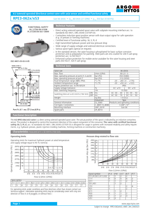
RPE3-062x/xS3Size 06 (D03) • Q max 80 l/min (21 GPM) • p max 350 bar (5100 PSI)Ports P , A, B, T - max. ∅7,5 mm (0.29 in)ISO 4401-03-02-0-05TPBAG0,75 (0.03)4xM5-6Hx1315,5 (0.61)31,75 (1.25)5,1 (0.20)25,9 (1.16)31 (1.22)12,7 (0.50)21,5 (0.85)30,2 (1.18)40,5 (1.59)12424281620325467080102030405060(21.1)(18.5)(7.9)(2.6)21(120)(175)(60)(350)(406)(235)(290)(464)3(5.3)(10.6)(13.2)(15.9)87080(21.1)(18.5)(1450)(2176)(725)(4351)(5076)(2901)(3626)010203040505060(7.9)(2.6)6325, 415, 6, 77(5.3)(10.6)(13.2)(15.9)1, 2, 3, 4Spool symbolP-A P-B A-T B-T P-T Z11,R1,R21,X11,X321122C1155562H1111122Z51,H5112C51124R3112K1112R303112X301123V5133Spool symbolZ11C11H11R11R21C51Z51R31H51X11K11X32V51R30X30154235144263377FUNCTIONAL SAFETY SIL 3 ČSN EN 61508PL d ČSN EN ISO 13849Subject to change · RPE3-062x/xS3_4087_3en_04/2023Page 14/2 Solenoid operated directional control valve with axial sensor and certified functional safetyTechnical FeaturesCharacteristics measured at ν = 32 mm 2/s (156 SUS)Pressure drop related to flow rate Technical DataO p e r a t i n g p r e s s u r e p [b a r (P S I )]Flow Q [l/min (GPM)]Flow Q [l/min (GPM)]P r e s s u r e d r o p Δp [b a r (P S I )]Operating limits›Direct acting solenoid operated spool valve with subplate mounting interface acc. to standards ISO 4401, DIN 24340 (CETOP 03)›Contactless inductive spool position sensor with dual output signal for safe operation (e.g. of presses or forming machines)›Certified level of functional safety: SIL 3, PL d›High transmitted hydraulic power and low pressure drop›Wide range of supply voltages and solenoid electrical connections ›Various spool types (special on request)›In the standard version, the valve housing is phosphated for basic surface corrosionprotection and as preparation for painting. Steel parts are zinc-coated for 240 h salt spray protection acc. to ISO 9227›Enhanced surface protection for mobile sector available for the valve housing and steelparts (ISO 9227, 520 h salt spray)Valve size 06 (D03)Max. flowl/min (GPM)80 (21.1)Max. operating pressure at ports P , A and B bar (PSI)350 (5080)Max. operating pressure at port T bar (PSI) 210 (3050)Fluid temperature range (NBR, FPM)°C (°F)-20 ... +80 (-4 ... +176)Ambient temperature range°C (°F)-20 ... +50 (-4 (122)Ingress protection acc. to EN 60529IP65Supply voltage tolerance %AC: ±10DC: ±10Max. switching frequency1/h 15 000Switching time at ν=32 mm 2/s (156 SUS)ONms AC: 30 ... 40DC: 30 ... 50OFFms AC: 30 ... 70DC: 10 ... 50Weightkg (lbs) 1.9 (4.2)Datasheet Type General information GI_0060Products and operating conditions Coil types / connectors C_8007 / K_8008C22B* / K*Mounting interface SMT_0019Size 06Spare partsSP_8010Operating limits for maximum hydraulic power at rated temperature and supply voltage equal to 90 % nominal.For operating limits under conditions and flow directions other than shown contact our technical support. Admissible operating limits may be considerably lower with only one direction of flow (A or B plugged, or without flow.)Functional DescriptionThe 4/2 RPE3-06x/xS3 valve is a direct acting solenoid operated spool valve. The actual position of the spool is indicated by an inductive contactless sensor. The product is designed to control the movement direction of the output component of the consumer. The valve with certified functional safety SIL 3, PL d , acc. to standards ISO 4401, DIN 24340 (CETOP 03) is designed for usage in systems with increased reliability and safety require-ments, e.g. hydraulic presses, plastic injection molding machines, forming machines or construction machinery.R21R11V51R30Z51R31C51H51X30K11Z11C11H11X32X11Page 2Ordering CodeSpool SymbolsType Symbol InterpositionType Symbol InterpositionRPE3 - 06 2/ N1 S3 -01200024000270020500024501206023050E1E2E3A E4A E5E8E9E12A E13ASpool symbolssee the table “Spool Symbols“Valve sizeNo designation A B No designation VConnector EN 175301-803-A E1 with quenching diodeAMP Junior Timer - axial direction (2 pins; male)E3A with quenching diodeEN 175301-803-A with integrated rectifierLoose conductors (two insulated wires)E8 with quenching diodeDeutsch DT04-2P - axial direction (2 pins; male)E12A with quenching diodeNumber of spool positions Manual override cap nut covered4/2 Solenoid operated directional control valve Surface treatmentstandard zinc-coated (ZnCr-3), ISO 9227 (240 h)zinc-coated (ZnNi), ISO 9227 (520 h)Seals NBRFPM (Viton)Spool monitoringaxial sensor with two outputsRated supply voltage of solenoids (at the coil terminals)12 V DC / 2.72 A 24 V DC / 1.29 A 27 V DC / 1.07 A 205 V DC / 0.15 A24 V AC / 1.56 A / 50 (60 Hz)120 V AC / 0.26 A / 60 Hz 230 V AC / 0.15 A / 50 (60) Hz- For AC voltage supply use coils with connector type E5.- For other solenoid voltage supply options see datasheet C_8007.- The solenoid operated valves are delivered without connectors. For available connectors see datasheet K_8008.- Mounting bolts M5 x 45 DIN 912-10.9 or studs must be ordered separately. Tightening torque is 8.9+1 Nm (7+0.7 Ibf.ft).- Besides the commonly used valve versions there are other special models available. Contact our technical support for their identification, feasibility and operating limits.4577)(1.32,5(1.27)52 (2.05)32,5(1.28)A38,2 (1.51)46,3 (1.82)Solenoid Coil in millimeters (inches)Note:A = Standard 300 mm (11.8 in)other lengths on demandE1, E2Ingress protection IP65E3A, E4AIngress protection IP67E5Ingress protection IP65E8, E9E12A, E13AIngress protection IP67 / IP69KThe indicated IP protection level is only achieved if the connector is properly mounted.UbOUT 1OUT 2GNDACDCDC stOscilDC 1142379,5 (3.13)aDesignation N1- cap nut covered12434-pin connector with the thread M12(0.2±0.04 in)5 (0.2) [mm (in)]Switching diagram of contacts:0 max. voltage 1.8 V DC1 min. voltage Ub – 2.5 V DC← Adjusted switching pointPin 4Pin 2110,50,1 mm±0002,5 mm(0,98 in), spool rebuilded by solenoidPage 3Manual Override in millimeters (inches)Spool Position SensorTechnical DataMax. pressure resistance bar (PSI)315 (dynamic)Operating temperature °C (°F)-20 ... +85 (-4 ... +185)Storage temperature °C (°F)-25 ... +85 (-13 (185)Supply voltage UbV 24 V DC ± 20 %Current consumption (max.)mA 20Output voltage (min.)V min. Ub-2.5 V Output currentmA max. 250Ingress protection (EN 60529)IP65Hysteresis of switching point (max.)mm (in)0.06 (0.002)Reproducibility at 25 °C (77 °F)mm (in)± 0.02 (± 0.0008)Temperature drift mm / °C 0.002Weightkg (lbs)0.250 (0.55)Connection scheme of the spool position sensorDescription of sensor:Contactless inductive sensor with two transistor type switching outputs. The output OUT 2 is inverted. The dual output signal is protected against mutual interference and increases the reliability of the spool end position signalization, which is important for command system ensuring the safety of such machines like presses, forming machines etc. The sensor is set at the factory so that it switches when the spool is moved from the basic position by 0.5 ± 0.1 mm. The relative position of the sensor components is indicated in red .In case of solenoid or power failure, the spool of the valve can be shifted by manual override as long as the pressure in port T does not exceed 25 bar (363 PSI). For alternative manual overrides contact our technical support.Plastic nut 3+1 Nm (2.2+0.7 lbf.ft)±±~10 Nm (7.4 lbf.ft)Required surface quality ofthe counterpartPage 4Dimensions in millimeters (inches)Valve with one solenoid …a“Plastic nut 3+1 Nm (2.2+0.7 lbf.ft)Valve with one solenoid …b“Mounting screws 8.9+1 Nm (7+0.7 lbf.ft)M5 x 45 DIN 912-10.9Spool symbols X11, K11, Z11...Spool symbols R11, Z51, R31...(depending on the zero setting)Examples of safe connectionExample of valve connection with sensor, providing functional safety Pl. dExample of redundant connection of two valves to achieve functional safety Pl. eValve safety functionmachinecontrol systemmachinecontrol systemspool position signalspool position signal spool position signaldirectional control valvedirectional control valvesupply voltage of solenoidsupply voltage of solenoid (directional control valve)supply voltage of solenoid (directional valve, poppet type, blocking)controlled equipment (cylinder)controlled equipment (cylinder)Suitable redundant connection of another, for exampleblocking poppet, valve, can achieve an increase in functional safety.The condition for using the safety function of the valve is the correct connection to the hydraulic circuit and integration into the control system of the machine. The basic rule is that the spool is in the safety position when the solenoid is off. This condition corresponds to a control system failure or a power failure of the machine.。
ROHS测试仪器介绍
实验室仪器设备介绍1 微波消解/萃取仪名称:微波消解/萃取仪厂家:麦尔斯通Milestone型号:ETHOS A T260 最高工作温度:260℃最高工作功率:1000W作用:1.将固体样品消解为仪器能够测试的样品溶液。
2.萃取样品中的目标物质微波消解试样的原理称取的样品置于消解罐中,加入适量的酸。
通常是选用HNO3、HCI、HF、H2O2等,把罐盖好,放入炉中。
当微波通过试样时,极性分子随微波频率快速变换取向,2450MHz的微波,分子每秒钟变换方向2.45×10⁹次,分子来回转动,与周围分子相互碰撞摩擦,使样品温度急剧上升,并产生大量的气体。
罐内迅速形成的高温高压使样品快速消解2 实验室仪器设备介绍-ICP/AES名称:电感耦合等离子体原子发射光谱仪ICP-AES厂家:博精PE型号:Optima 2100DV测试对象:镉Cd、铅Pb、汞Hg、总铬Cr也可以测试其他各种元素含量,74种。
ICP-AES工作原理:样品由载气(氩气)带入雾化系统进行雾化后,以气溶胶形式进入等离子体的轴向通道,在高温和惰性气氛中被充分蒸发、原子化、电离和激发,发射出所含元素的特征谱线。
根据特征谱线的存在与否,鉴别样品中是否含有某种元素(定性分析);根据特征谱线强度确定样品中相应元素的含量(定量分析)。
3 实验室仪器设备介绍-UV/Vis名称:紫外-可见分光光度计UV-Vis厂家:岛津Shimadzu型号:UV-2450测试对象:六价铬Cr+6,甲醛从UV-Vis工作原理:光源辐射出的光,经仪器单色器分光后成为单色光。
当单色光通过溶液时,一部分被吸收,吸收的大小与溶液的厚度和浓度的关系符合朗伯-比尔定律。
朗伯-比尔定律为A=lg(1/gT)=εbc (1)式中A——溶液的吸光度T——溶液的透过率b——溶液厚度,cmc——溶液浓度,mol/Lε——摩尔吸收系数,1/mol·cm当光程长度和摩尔吸收系数一定时,吸光度A与溶液中待测组分浓度成正比,利用此定律进行定量分析4 实验室仪器设备介绍-GC/MS名称:气相色谱-质谱联用仪GCMS厂家:岛津Shimadzu型号:QP2010测试对象:多溴联苯PBBs多溴二苯醚PBDEs各种有机化合物实验室仪器设备介绍-GC/MSGCMS工作原理:GCMS利用气相色谱GC的分离能力让混合物中的组分分离,并用质谱MS鉴定分离出来的组分(定性分析)以及各个组分精确的量(定量分析)。
罗斯蒙特3051压力变送器产品说明书
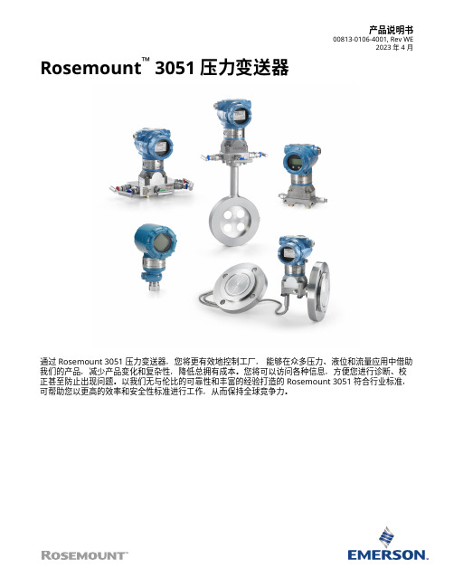
产品说明书00813-0106-4001, Rev WE2023 年 4 月Rosemount™ 3051 压力变送器通过 Rosemount 3051 压力变送器,您将更有效地控制工厂,能够在众多压力、液位和流量应用中借助我们的产品,减少产品变化和复杂性,降低总拥有成本。
您将可以访问各种信息,方便您进行诊断、校正甚至防止出现问题。
以我们无与伦比的可靠性和丰富的经验打造的 Rosemount 3051 符合行业标准,可帮助您以更高的效率和安全性标准进行工作,从而保持全球竞争力。
Rosemount 30512023 年 4 月内容建立压力测量标准 (2)Rosemount 3051C 共平面压力变送器订购信息 (6)Rosemount 3051T 直连式变送器订购信息 (18)Rosemount 3051CF 流量计选择指南 (28)Rosemount 3051L 液位变送器订购信息 (62)技术规格 (74)Rosemount 3051 产品认证 (91)尺寸图 (92)选项外, (106)建立压力测量标准经实践检验的一流性能、可靠性和安全性■超千万装机量■参考精度为量程的 0.04%■安装总性能为量程的 0.14%■稳定性可保持在 URL 的 0.1% 长达 12 年■SIL 2/3 认证(IEC 61508)Coplanar ™平台增强安装和应用灵活性■通过集成的差压流量计、差压液位解决方案和一体化阀组提高可靠性和性能。
■安装方便,所有方案都全面组合,并经过渗漏测试和标定。
■丰富的产品满足您的应用需求。
高级功能Bluetooth ® 技术■提高生产力、可靠性和人员安全性。
无需高温作业许可。
无需攀爬储罐或建筑脚手架。
■快速组态、检修和排除故障,所有设备对技术人员触手可及,速度比传统 HART ® 连接快十倍。
诊断■回路完整性诊断将连续地监测电路,检测影响通讯信号的问题,并提供腐蚀、外罩进水或电源不稳定等警报。
OMRON G3VM-61GR1 MOS FET 关联器说明书

1MOS FET Relays with 1-A switching Designed for Switching Minute Signals and Analog Signals.•Upgraded G3VM-S1 Series.•Continuous load current of 1 A.■Application Examples■Terminal Arrangement/Internal Connections■List of Models*The AC peak and DC value are given for the load voltage.■Absolute Maximum Ratings (Ta = 25°C)RoHS compliantNote: The actual product is marked differently from theimage shown here.•Semiconductor test equipment •Test & Measurement equipment •Communication equipment •Data loggersOMRON logo Pin 1 markModel name LOT.No.932Mold pin mark *Note:The actual product is marked differently from the image shown here.*The indentation in the corner diagonally opposite from the pin 1 mark is from a pin on the mold.Package type Contact formTerminalsLoad voltage (peak value) *Model Minimum package quantity Number per tube Number per tape and reelSOP41a(SPST-NO)Surface-mounting Terminals60 VG3VM-61GR1100-G3VM-61GR1 (TR)-2,500ItemSymbol Rating Unit Measurement conditions I n p u tLED forward current I F 50mANote: 1. The dielectric strength between the input andoutput was checked by applying voltagebetween all pins as a group on the LED side and all pins as a group on the light-receiving side.Repetitive peak LED forward current I FP 1 A 100 µs pulses, 100 pps LED forward current reduction rate ∆I F /°C −0.5 mA/°C Ta ≥ 25°C LED reverse voltage V R 5 V Connection temperature T J 125 °CO u t p u t Load voltage (AC peak/DC)V OFF 60 V Continuous load current (AC peak/DC)I O 1000mA ON current reduction rate ∆I O /°C −13.3mA/°C Ta ≥ 25°C Connection temperature T J 125 °C Dielectric strength between I/O (See note 1.)V I-O 1500Vrms AC for 1 minAmbient operating temperature Ta −20 to +85°C With no icing or condensation Ambient storage temperature Tstg −40 to +125°C With no icing or condensation Soldering temperature -260°C10 s2G3VM-61GR1MOS FET Relays■Recommended Operating ConditionsUse the G3VM under the following conditions so that the Relay will operate properly.■Engineering Data■Safety Precautions•Refer to "Common Precautions" for all G3VM models.ItemSymbolMinimumTypicalMaximumUnitLoad voltage (AC peak/DC)V DD --48 VOperating LED forward current I F 5 1020mA Continuous load current (AC peak/DC)I O --1000mA Ambient operating temperatureTa 25-60°CLED forward current vs. AmbienttemperatureContinuous load current vs. Ambient temperatureLED forward current vs. LED forward voltageContinuous load current vs. On-state voltageOn-state resistance vs. Ambient temperatureTrigger LED forward current vs. Ambient temperatureTurn ON, Turn OFF time vs. LED forward currentTurn ON, Turn OFF time vs. Ambient temperatureCurrent leakage vs. Ambient temperatureI F - TaAmbient temperature Ta (°C)L E D f o r w a r d c u r r e n t I F (m A )20406080100-20120100 80 60 40 020I O - TaAmbient temperature Ta (°C)-20120100 80 60 4002000.20.40.60.811.2C o n t i n u o u s l o a d c u r r e n t I O (A )I F - V FLED forward voltage V F (V)0.11101000.30.5355030L E D f o r w a r d c u r r e n t I F (m A )I O - V ONOn-state voltage V ON (mV)-1.2-1.0-0.8-0.6-0.4-0.200.20.40.60.81.01.2C o n t i n u o u s l o a d c u r r e n t I O (A )R ON - TaAmbient temperature Ta (°C)00.10.20.30.40.50.60.70.8O n -s t a t e r e s i s t a n c e R O N (Ω)I FT - TaAmbient temperature Ta (°C)0.00.20.40.60.81.01.21.4T r i g ge r L E Df o r w a r d c u r r e n t I F T (m A )t ON , t OFF - I FLED forward current I F (mA)0.1110T u r n O N , T u r nO F F t i m e t O N , t O F F (m s )t ON , t OFF - TaAmbient temperature Ta (°C)0.1110T u r n O N , T u r n O F F t i m e t O N , t O F F (m s )I LEAK - TaAmbient temperature Ta (°C)0.05350.30.50.030.010.1110C u r r e n t l e a k a g e I L E A K (n A )■Dimensions(Unit: mm)Note:The actual product is marked differently from the image shown here.Actual Mounting Pad Dimensions(Recommended Value, TOP VIEW)Note: The actual product is marked differently from the image shown here.* The indentation in the corner diagonally opposite from the pin 1 mark is from a pin on the mold.0.4Surface-mounting TerminalsWeight: 0.1 g• Application examples provided in this document are for reference only. In actual applications, confirm equipment functions and safety before using the product.• Consult your OMRON representative before using the product under conditions which are not described in the manual or applying the product to nuclear control systems, railroad systems, aviation systems, vehicles, combustion systems, medical equipment, amusement machines, safety equipment, and other systems or equipment that may have a serious influence on lives and property if used improperly. Make sure that the ratings and performance characteristics of the product provide a margin of safety for the system or equipment, and be sure to provide the system or equipment with double safety mechanisms.Cat. No. K178-E1-010412(0412)(O)Note: Do not use this document to operate the Unit.OMRON CorporationELECTRONIC AND MECHANICAL COMPONENTS COMPANYContact: /ecb。
CSNC361中文资料

CSNC361中⽂资料Closed Loop Current SensorsFEATURES ?Current sensing up to 1200amps ?Measures AC,DC and impulse currents ?Lowest cost/performance ratio ? Rapid response,no overshoot ?High overload capacity ?High level of electrical isolation between primary and secondary circuits ?Small size and weight CLOSED LOOP SENSORS Closed loop current sensors measure AC,DC and impulse currents over 0-25,0-50,0-100,0-600and 0-1200Amp rang-es.The CSN Series is based on the princi-ples of the Hall effect and the null balance or zero magnetic flux method (feedback system).The magnetic flux in the sensor core is constantly controlled at zero.The amount of current required to balance zero flux is the measure of the primary current flowing through the conductor,multiplied by the ratio of the primary to secondary windings.This closed loop current is the output from the device and presents an image of the primary current reduced by the number of secondary turns at any time.This current can be expressed as a voltage by passing it through a resistor.CATALOG NUMBER SYSTEM PLEASE NOTE:This matrix is intended only to aid you in identifying sensor cata-log listings.It is not all-inclusive,and must not be used to form new listings.Example:CSNA111CSN Closed Loop Current SensorCurrent Range (Peak/RMS nom.)A ±70A/50A rms nom.B ±100A/50A rms nom.C ±90A/50A rms nom.D ±22A/15A rms nom.E ±36A/25A rms nom.F ±150A/100A rms nom.J ±600A/300A rms nom.K ±1200A/500A rms nom.L ±600A/300A rms nom.M±1200A/500A rms nom.P ±90A/50A rms nom.R ±200A/125A rms nom.T ±150A/50A rms nom.Supply Voltage 1±15V 2±13V 3±5V 4±12V to 18V 5±15V to 24V 6±12V to 15VCoil Characteristics 11:1000turns/90?@70°C 21:2000turns/160?@70°C 31:2000turns/130?@70°C 41:1000turns/50?@70°C 51:1000turns/110?@70°C 61:1000turns/30?@70°C 71:2000turns/80?@70°C 81:2000turns/25?@70°C91:5000turns/50?@85°CHousing Material 1Polycarbonate/ABS blend PDFINFOClosed Loop Current Sensors*Contact the 800number for more information.SPECIFICATIONSCatalog Listing CSNA111CSNB121CSNB131CSNE151Offset Current @25°C,mA max.±0.20±0.10±0.10±0.10Temperature Drift,0to 70°C,mA ±0.35typ.±0.20typ.±0.20typ.±0.17typ.±0.60max.±0.30max.±0.30max.±0.60max.Linearity 0.1%0.1%0.1%0.2%SupplyVoltage ±15V ±15V ±15V ±15VGalvanic Isolation @50Hz/1min. 2.5kV rms 5kV rmsAccuracy ±0.5%of I N (nominal Current)at 25°CResponse Time <1?sBandwidth DC to 150kHzTemperature Operating:0to 70°C (32to 150°F)Storage:?25to 85°C (?13to 185°F)Primary Circuit Connection Thru-hole Thru-hole Thru-hole Invasive on 10pins Secondary Circuit Connection 3Pins 3Pins 3Pins 3PinsCurrent Drain 10mA (no load current)+output current (secondary current)‘‘In-Out’’Sense Signal To obtain positive measuring current on O/P terminal,current must flow in direction of arrow Mounting PCB,3pins,hole size 0.95mm PCB,13pins PRIMARY PIN CONNECTIONS FOR CSNE151Primary CurrentPrimary Turns Nom.I DN (A)Max.I D (A)OutputCurrent (mA)PrimaryResistance (m ?)Primary PinConnections 12436250.32121824 1.1381224 2.546924 4.455725 6.3WIRING DIAGRAMSCSNA111/CSNB121/CSNB131CSNE151PDFINFOCurrentClosed Loop Current Sensors MOUNTING DIMENSIONS(for reference only) CSNA111,CSNB121,CSNB131CSNE151/CSNE381CSNH151PDFINFOClosed Loop Current SensorsSPECIFICATIONSCatalog ListingsCSNJ481CSNJ481-002CSNK591CSNK591-002CSNJ481-001CSNJ481-003CSNK591-001CSNK591-003Offset Current @25°C,mA max.±0.30±0.30±0.20±0.20Temperature Drift,0to 70°C,mA ±0.30typ.±0.30typ.±0.20typ.±0.20typ.±0.50max.±0.50max.±0.30max.±0.30max.Linearity±0.1%±0.1%±0.1%±0.1%Supply Voltage ±12to ±18V ±12to ±18V ±15to ±24V ±15to ±24V Galvanic Isolation @50Hz/1min.7.5kV rms 7.5kV rms 6kV rms 6kV rmsAccuracy ±0.5%of I N (nominal Current)at 25°CResponse Time <1?sBandwidth DC to 150kHzOperating Temperature ?40to 85°C 0to 70°C ?40to 85°C 0to 70°C (?40to 185°F)(32to 158°F (?40to 185°F)(32to 158°F)Storage Temperature ?40to 90°C ?25to 85°C ?40to 90°C ?25to 85°C (?40to 194°F)(?13to 85°F (?40to 194°F)(? 13to 85°F)Primary Circuit Connection Thru-hole or busbar Thru-hole or busbar Thru-hole or busbar Thru-hole or busbar Secondary Circuit Connection 3pins 3pins 3pins 3pinsCurrent Drain 14mA (no load current)+output current 22mA (24V)+output current‘‘In-Out’’Sense Signal To obtain positive measuring current on O/P terminal,current must flow in direction of arrow Mounting Faston,3pins Push-on (spade),3terminalsWIRING DIAGRAMPDFINFOCurrentClosed Loop Current Sensors MOUNTING DIMENSIONS(for reference only) CSNJ481CSNK591PDFINFOClosed Loop Current SensorsSPECIFICATIONSCatalog ListingsCSNL181CSNM191Offset Current@25°C,mA max.±0.30±0.20Temperature Drift,0to70°C,mA±0.30typ.±0.20typ.±0.50max.±0.30max.Linearity±0.1%±0.1%Supply Voltage±12to±18V±12to±18VGalvanic Isolation@50Hz/1min.7.5kV rms7.5kV rmsAccuracy±0.5%of I N(nominal Current)at25°CResponse Time500ns<1?sBandwidth DC to150kHzOperating Temperature?40to85°C(?40to185°F)Storage Temperature?40to90°C(?40to194°F)Primary Circuit Connection Thru-hole Thru-holeSecondary Circuit Connection3pins3pinsCurrent Drain14mA(no load current)+output current‘‘In-Out’’Sense Signal To obtain positive measuring current on O/P terminal,current must flowin direction of arrowMounting Faston,3pinsWIRING DIAGRAMPDFINFO CurrentClosed Loop Current Sensors MOUNTING DIMENSIONS(for reference only) CSNL181CSNM191PDFINFOClosed Loop Current SensorsSPECIFICATIONSCatalog ListingsCSNP661CSNT651CSNF161CSNF151CSNR161CSNR151Offset Current @25°C,mA max.±0.20±0.10±0.20±0.10±0.20±0.10Temperature Drift,0to 70°C,mA ±0.30typ.±0.15typ.±0.30typ.±0.15typ.±0.30typ.±0.15typ.±0.50max.±0.25max.±0.50max.±0.25max.±0.60max.±0.30max.Linearity ±0.1%±0.1%±0.1%±0.1%±0.1%±0.1%Supply Voltage ±12to 15V ±12to 15V ±12to 15V ±12to 15V ±12to 15V ±12to 15V Galvanic Isolation @50Hz/1min.3kV rms 3kV rms 3kV rms 3kV rms 3kV rms 3kV rms Accuracy ±0.5%of I N (nominal Current)at 25°CResponse Time <500nsBandwidth DC to 150kHzOperating Temperature ?40to 85°C (?40to 185°F)?40to 85°C (?40to 185°F)Storage Temperature ?40to 90°C (?40to 194°F)?40to 90°C (?40to 194°F)Primary Circuit Connection Thru-holeSecondary Circuit Connection 3pinsCurrent Drain 10mA (no load current)+output current 14mA (no load current)+output current‘‘In-Out’’Sense Signal To obtain positive measuring current on O/P terminal,current must flow in direction of arrow Mounting 3pinsPin Style A A B B B B WIRING DIAGRAMPDFINFOCurrentClosed Loop Current Sensors MOUNTING DIMENSIONS(for reference only)PDFINFO。
最新CEM公司MARS6微波消解仪技术参数--40位

微波消解仪技术指标1.应用范围1.1 主要用于实验室中各种样品的消解前处理,为原子吸收(AA),等离子发射光谱(ICP),ICP-MS 等制备样品。
2.技术要求2.1 工作条件2.1.1 电源:220VAC±10%,环境温度:10-40℃。
2.2 仪器性能及参数注:*微波仪器生产厂家需具有“微波仪器设计、制造”的ISO9001认证证书,无重大安全事故记录(厂家需出具微波仪器设计和制造资质证明材料原件);*2.2.1主机专业一体化设计,具备安全可视窗。
微波源采用专业磁控管,微波输出功率≥1800W (需提供具体的功率数据图并加盖公章) 。
2.2.2主机配备POWER MAX微波能量最大化系统,瞬时同步大功率平台,保证微波输出能量最大化,三维微波输出,确保难溶样品消解完全。
2.2.3视频监控系统,可实时在线与观察反应状况,同时与以太网连用,可实现实时远程监测和控制反应状况。
*2.2.4可选配一体化打印机,可实时在线打印功率,温度,压力等数据和曲线,同时可打印系统参数和方法(提供仪器图片并加盖公章)。
*2.2.5主机配备接口,采用至少6个USB接口,可通过优盘等导入导出应用方法,升级系统软件;采用至少2个以太网网口,可实现在线维修,传导数据,视频教程等。
2.2.6主机内置灯光识别系统,可通过灯光信号变化反馈反应状况和不同的消解阶段。
2.2.7 内置影音系统,双声道扬声器,用户可以播放中文语言的帮助文件和视频培训教程。
2.3 操作系统:*2.3.1采用开放式Linux操作平台,结合One Touch技术,用户只需选择样品类型,仪器自动匹配消解程序和温度、压力、时间等消解参数,实现一键式消解。
*2.3.2中文操作界面,用户使用方便快捷。
2.3.3内置中文视频培训教程和帮助文件。
2.3.4 内置一键式消解模式和经典消解模式两种消解模式,用户可自由选择和切换。
2.3.5内置EPA、GB等标准通用方法,用户可以直接选择。
罗克福德·福斯盖特 RFX3-FSE 西刺穿越豪华豪车前扬声器套件说明书

I n s t a l l a t i o n & O p e r a t i o nR F X 3-F S E3 R O C K F O R D F O S G A T E .C O M600 S o u t h R o c k f o r d D r i v e • T e m p e , A r i z o n a 85281 U n i t e d S t a t e s D i r e c t : (480) 967-3565 • T o l l F r e e : (800) 669-9899I n s t a l l a t i o n a s s i s t a n c e a v a i l a b l e a t :w w w .r o c k f o r d f o s g a t e .c o m /r e c h2Dear Customer,Congratulations on your purchase of the world’s finest brand of audio products. At Rockford Fosgate we are fanatics about musical reproduction at its best, and we are pleased you chose our product. Through years of engineering expertise, hand craftsmanship and critical testing procedures, we have created a wide range of products that reproduce music with all the clarity and richness you deserve.For maximum performance we recommend you have your newRockford Fosgate product installed by an Authorized Rockford Fosgate Dealer, as we provide specialized training through Rockford Technical Training Institute (RTTI). Please read your warranty and retain your receipt and original carton for possible future use.Great product and competent installations are only a piece of the puzzle when it comes to your system. Make sure that your installer is using 100% authentic installation accessories from Rockford Fosgate in your installation. Rockford Fosgate has everything from RCA cables andspeaker wire to power wire and battery connectors. Insist on it! After all, your new system deserves nothing but the best.To add the finishing touch to your new Rockford Fosgate image order your Rockford accessories, which include everything from T-shirts to hats.Visit our web site for the latest information on all Rockford products; or, in the U.S. call 1-800-669-9899 or FAX 1-800-398-3985. For all other countries, call +001-480-967-3565 or FAX +001-480-966-3983.Table of Contents If, after reading your manual, you still have questions regarding this product, we recommend that you see your Rockford Fosgate dealer. If you need further assistance, you can call us direct at 1-800-669-9899. Be sure to have your serial number, model number and date of purchase available when you call.SafetyThis symbol with “WARNING” is intended to alert the user to the presence of important instructions. Failure to heed the instructions will result in severe injury or death.This symbol with “CAUTION” is intended to alert the user to the presence of important instructions. Failure to heed the instructions can result in injury or unit damage.• To prevent injury and damage to the unit, please read and follow the instructions in this manual. We want you to enjoy this system, not get a headache.• If you feel unsure about installing this system yourself, have it installed by a qualified Rockford Fosgate technician.• Before installation, disconnect the battery negative (-)terminal to prevent damage to the unit, fire and/or possible injury.ContentsInstallation ToolsThe following is a list of suggested tools needed for installation:Introduction©2017 Rockford Corporation. All Rights Reserved. ROCKFORD FOSGATE and associated logos where applicable are registered trademarks of Rockford Corporation in the United States and/or other countries. All other trademarks are the property of their respective owners. Specifications subject to change without notice.2Introduction 3Installation 4Warranty• T30 Torx • 10 mm Socket • Ratchet • Wire Cutters• Panel Tool • (2) Front Speaker Enclosures • Mounting Hardware • Plastic Wire Tie Wraps• Wire Harness • Foam PadsPRACTICE SAFE SOUNDContinuous exposure to sound pressure levels over 100dB may cause permanent hearing loss. High powered auto sound systems may produce sound pressure levels well over 130dB. Use common sense and practice safe sound.Installation ConsiderationsThis section focuses on some considerations for installing your Can-Am Maverick X3 front speaker enclosures. These speaker enclosures are designed to work in conjunction with Rockford’s other X3 specific audio kits and parts.If you feel unsure about installing this system yourself, have it installed by a qualified technician.When drilling holes, make sure what is on the other side. Be sure that any electrical, fuel lines or any other important components are free and clear from the area.Before installation, disconnect the batterynegative (-) terminal to prevent damage tothe unit, fire and/or possible injury.Before beginning any installation, followthese simple rules:Be sure to carefully read and understandthe instructions before attempting to installthese speaker enclosures.• Consult your UTV’s service manual for model specific information.Models may differ from year to year depending on factory options and aftermarket accessories added.• This speaker kit is specifically designed to work with RockfordFosgate’s PM and RM series of speakers.• With the addition of an amplifier or source unit, be sure that your current charging system is in proper working order.• Visit for more comprehensive productinformation.• Visit our YouTube channel for comprehensive installation videos demonstrating complete installation guides and install tips.Can-Am Maverick X3 (2 & 4 seat models)These front speaker enclosures are designed to work with Rockford Fosgate’s RFX3-K4 / RFX3-K8 amplifier wiring kits and RFX3-PMXDK dash kit. The enclosure can be installed in both 2-seat and 4-seat models replacing the factory dash panels.Step 1. Remove the fuse cover and the (4) plastic rivets that are adjacent to the fuse panel access hole.InstallationStep 2. Remove the remaining screws that secure the driver /passenger dash panel.NOTE: There are (2) factory clips that need to be transferred from the original panels to the new Rockford panels.Step 3. Mount the new speaker panels using the existing hardware.Step 4. Place speaker harness down the speaker cutout hole androute toward the center of the vehicle to behind the fuse blockaccess hole.Step 5. Connect the speaker harness to the speaker.Step 6. Secure the speaker with the supplied speaker hardware.Step 7. Repeat steps for the enclosure on the other side.Step 8. Feed the speaker wire up into the dash and connect to either the source unit or amplifier.Step 9. Power up and test the systemStep 10. Reinstall the fuse cover.ClipClip3WarrantyRockford Corporation offers a limited warranty on Rockford Fosgate products on the following terms:Length of WarrantyPOWER Amplifiers – 2 YearsBMW® Direct Fit Speakers – 2 YearsPUNCH® & PRIME® Amplifiers – 1 YearSpeakers, Signal Processors, Accessories and Capacitors – 1 YearAll marine, motorcycle, motorsport products - 2 YearsAny Factory Refurbished Product – 90 Days (receipt required)What is CoveredThis warranty applies only to Rockford Fosgate products sold to consumers by authorized Rockford Fosgate dealers in the United States of America.Products purchased by consumers from an Authorized Rockford Fosgate Dealer in another country are covered only by that country’s Distributor and not by Rockford Corporation.Who is CoveredThis warranty covers only the original purchaser of Rockford product purchased from an authorized Rockford Fosgate dealer in the United States. In order to receive service, the purchaser must provide Rockford with a copy of the receipt stating the customer name, dealer name, product purchased and date of purchase.Products found to be defective during the warranty period will be repaired or replaced (with a product deemed to be equivalent) at Rockford’s discretion.What is Not Covered1. Damage caused by accident, abuse, improper installation, operations, theft, water (on non-Element Ready products).2. Any cost or expense related to the removal or reinstallation of product.3. Service performed by anyone other than Rockford or an authorized Rockford Fosgate service center.4. Any product which has had the serial number defaced, altered, or removed.5. Subsequent damage to other components.6. Any product purchased outside the U.S.7. Any product not purchased from an authorized Rockford Fosgate dealer. Refer to dealer locator for more detail.Limit on Implied WarrantiesAny implied warranties including warranties of fitness for use and merchantability are limited in duration to the period of the express warranty set forth above. Some states do not allow limitations on the length of an implied warranty, so this limitation may not apply. No person is authorized to assume for Rockford Fosgate any other liability in connection with the sale of the product.How to Obtain ServicePlease call 1-800-669-9899 for Rockford Customer Service. You must obtain an RA# (Return Authorization number) to return any product to Rockford Fosgate. You are responsible for shipment of product to Rockford.EU WarrantyThis product meets the current EU warranty requirements, see your Authorized dealer for details.4。
SK35中文资料
SK35中⽂资料SK32 - SK36SURFACE MOUNT SCHOTTKY BARRIER RECTIFIERFeaturesMaximum Ratings and Electrical CharacteristicsCharacteristicSymbol SK32SK33SK34SK35SK36Unit Maximum Recurrent Peak Reverse Voltage V RRM 2030405060V Maximum RMS Voltage V RMS 1421283542V Maximum DC Blocking VoltageV DC 2030405060V Maximum Average Forward Rectified Current (See Fig. 1)I (AV) 3.0A Peak Forward Surge Current 8.3 ms single half sine-wave superimposed on rated load (JEDEC Method)I FSM 100A Maximum Instantaneous Forward Voltage at 3.0A (See Note 1)V F 0.500.75V Maximum DC Reverse Current at Rated @ T A =25°C DC Blocking Voltage (See Nore 1)@ T A = 100°C I R0.520mA Maximum Thermal Resistance (See Note 2)R Q JLR Q JA 1060°C/W Typical Junction Capacitance (See Note 3)C J 300pF Operating and Storage Temperature Range T J ,T STG-65 to +150°CNotes:1. Pulse Test Pulse Width 300m S, Duty Cycle 2%2. 8.0mm 2(0.13mm thick) land pads3. Measured at 1.0MHz and applied reverse voltage of4.0V.A BCDG HEJRatings at 25°C ambient temperature unless otherwise specified.Single phase, half wave, 60Hz resistive or inductive load.·For Surface Mounted Applications·High Temperature Metallurgically Bonded Contacts ·Capable of Meeting Environmental Standards of MIL-STD-19500·Plastic Material - UL Flammability Classification 94V-0·High Reliability·High Current Capability and Low VF ·Submersible Temperature of 265°C for 10 Seconds in Solder BathMechanical Data·Case:SMC, Molded Plastic·Terminals: Solderable per MIL-STD-202,Method 208·Polarity: Cathode Band·Approx. Weight:0.21 grams ·Mounting Position: AnySMCDim Min Max A 5.40 6.22B 6.107.11C 2.92 3.18D 0.150.40E7.558.13G 0.100.21H 0.76 1.52J2.002.62All Dimensions in mm204060801001201401501234LEAD TEMPERATURE (oC)Forward Derating CurveA V E R A G E O U T P U T C U R R E N T (A M P E R E S )11010020406080100NUMBER OF CYCLES @60HzMaximum Non-Repetitive Peak Forward Surge CurrentP E A K F O R W A R D S U R G E C U R R E N T (A M P E RE S )0.11.01010010100900REVERSE VOLTAGE (VOLTS)Typical Junction CapacitanceC A P A C I T A N C E (p F )0.10.30.50.70.9 1.10.11.01040INSTANTANEOUS FORWARD VOLTAGE (VOLTS)Typical Forward CharacteristicsI N S T A N T A N E O U S F O R W A R D C U R R E N T (A M P E R E S )。
赛米控丹佛斯电子 SEMiX603GAR066HDs 数据表

SEMiX ®3sTrench IGBT ModulesSEMiX603GAR066HDsFeatures•Homogeneous Si•Trench = Trenchgate technology •V CE(sat) with positive temperature coefficient•UL recognised file no. E63532Typical Applications*•Matrix Converter •Resonant Inverter•Current Source InverterRemarks•Case temperature limited to T C =125°C max.•Product reliability results are valid for T j =150°C•For short circuit: Soft R Goff recommended•Take care of over-voltage caused by stray inductanceAbsolute Maximum Ratings SymbolConditions Values UnitIGBT V CES T j =25°C 600V I C T j =175°CT c =25°C 720A T c =80°C541A I Cnom 600A I CRMI CRM = 2xI Cnom 1200A V GES -20 (20)V t psc V CC =360V V GE ≤ 15V V CES ≤ 600VT j =150°C6µs T j-40...175°C Inverse diode I F T j =175°CT c =25°C 771A T c =80°C 562A I Fnom600A I FRM I FRM = 2xI Fnom1200A I FSM t p =10ms, sin 180°, T j =25°C1800A T j-40 (175)°C Freewheeling diode I F T j =175°CT c =25°C 795A T c =80°C577A I Fnom 600A I FRM I FRM = 2xI Fnom1200A I FSM t p =10ms, sin 180°, T j =25°C1800A T j -40 (175)°C Module I t(RMS)T terminal =80°C600A T stg -40...125°C V isolAC sinus 50Hz, t =1min4000VCharacteristics SymbolConditions min.typ.max.UnitIGBT V CE(sat)I C =600A V GE =15V chiplevelT j =25°C 1.45 1.85V T j =150°C 1.7 2.1V V CE0T j =25°C 0.91V T j =150°C0.850.9V r CE V GE =15VT j =25°C 0.9 1.4m ΩT j =150°C1.42.0m ΩV GE(th)V GE =V CE , I C =9.6mA 55.86.5V I CES V GE =0V V CE =600V T j =25°C 0.150.45mA T j =150°C mA C ies V CE =25V V GE =0Vf =1MHz 37.0nF C oes f =1MHz 2.31nF C res f =1MHz1.10nF Q G V GE =- 8 V...+ 15 V 4800nC R GintT j =25°C0.67Ωt d(on)VCC =300V I C=600A V GE =±15V R G on =3ΩR G off =3ΩT j =150°C 150ns t r T j =150°C 145ns E on T j =150°C 12mJ t d(off)T j =150°C 1050ns t f T j =150°C 105ns E offT j =150°C43mJR th(j-c)per IGBT0.087K/W Inverse diodeV F = V EC I F =600AV GE =0V chipT j =25°C 1.4 1.60V T j =150°C 1.41.6V V F0T j =25°C 0.91 1.1V T j =150°C 0.750.850.95V r F T j =25°C 0.50.70.8m ΩT j =150°C0.80.9 1.1m ΩI RRM I F =600A di/dt off =3800A/µs V GE =-8VV CC =300VT j =150°C 350A Q rr T j=150°C63µC E rr T j =150°C 13mJ R th(j-c)per diode0.11K/W Freewheeling diode V F = V EC I F =600AV GE =0V chipT j =25°C 1.3 1.53V T j =150°C 1.31.5V V F0T j =25°C 0.91 1.1V T j =150°C 0.750.850.95V r F T j =25°C 0.40.60.7m ΩT j =150°C0.70.80.9m ΩI RRM I F =600A di/dt off =3800A/µs V GE =-8VV CC =300VT j =150°C 350A Q rr T j=150°C63µC E rr T j =150°C 13mJ R th(j-c)per diode0.11K/W Module L CE 20nH R CC'+EE'res., terminal-chip T C =25°C 0.7m ΩT C =125°C1m ΩR th(c-s)per module 0.04K/WM s to heat sink (M5)35Nm M t to terminals (M6)2.55Nm Nm w300g Temperatur Sensor R 100T c =100°C (R 25=5 k Ω)493 ± 5%ΩB 100/125R (T)=R 100exp[B 100/125(1/T-1/T 100)]; T[K];3550 ±2%KCharacteristics SymbolConditionsmin.typ.max.UnitSEMiX ® 3sTrench IGBT ModulesSEMiX603GAR066HDsFeatures•Homogeneous Si•Trench = Trenchgate technology •V CE(sat) with positive temperature coefficient•UL recognised file no. E63532Typical Applications*•Matrix Converter •Resonant Inverter•Current Source InverterRemarks•Case temperature limited to T C =125°C max.•Product reliability results are valid for T j =150°C•For short circuit: Soft R Goff recommended•Take care of over-voltage caused by stray inductanceFig. 1: Typ. output characteristic, inclusive R CC'+ EE'Fig. 2: Rated current vs. temperature I C = f (T C )Fig. 3: Typ. turn-on /-off energy = f (I C )Fig. 4: Typ. turn-on /-off energy = f (R G )Fig. 5: Typ. transfer characteristic Fig. 6: Typ. gate charge characteristicFig. 7: Typ. switching times vs. I C Fig. 8: Typ. switching times vs. gate resistor R GFig. 9: Typ. transient thermal impedance Fig. 10: Typ. CAL diode forward charact., incl. R CC'+EE'Fig. 11: Typ. CAL diode peak reverse recovery current Fig. 12: Typ. CAL diode recovery chargeThis is an electrostatic discharge sensitive device (ESDS), international standard IEC 60747-1, Chapter IX* The specifications of our components may not be considered as an assurance of component characteristics. Components have to be tested for the respective application. Adjustments may be necessary. The use of SEMIKRON products in life support appliances and systems is subject to prior specification and written approval by SEMIKRON. We therefore strongly recommend prior consultation of our staff.。
伊顿爱迪生系列 RK1 类双元件延时保险丝,0.25-60A 数据表
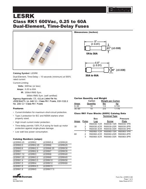
Agency Approvals: CE, cULus Listed file No. JDDZ.E4273, UL 248-12 – Class RK1 Fuses, CSA C22.2 No. 248.12 – Class RK1 Fuses
LESRK1.5 LESRK4
LESRK12
LESRK1.6 LESRK4.5 LESRK15
LESRK1.8 LESRK5
LESRK17.5
LESRK20 LESRK25 LESRK30 LESRK35 LESRK40 LESRK45 LESRK50 LESRK60
Carton Quantity and Weight
• Time-delay permits 130% FLA sizing for back-up motor protection against single-phase damage.
• Low watt loss power consumption.
Catalog Numbers (amps)
3 R60060-3CR R60060-3SR R60060-3PR
0723 BU-SB07255
Form No. LESRK 0-60 Page 1 of 2
Data Sheet #1311
Edison®
LESRK
Class RK1 600Vac, 0.25 to 60A Dual-Element, Time-Delay Fuses