The effect of the physico-chemical properties of cellulosic
抗冻剂对冷冻鱼糜蛋白理化和凝胶特性的影响综述_杨振 (1)

抗冻剂对冷冻鱼糜蛋白理化和凝胶特性的影响综述杨 振,孔保华*(东北农业大学食品学院,黑龙江 哈尔滨 150030)摘 要:冷冻储藏是一种广泛用于保存鱼糜制品的方法。
但是在储藏的过程中会使蛋白质发生冷冻变性,使鱼糜蛋白的空间构象发生变化,导致蛋白理化性质及凝胶特性发生变化,包括盐溶性蛋白含量、Ca 2+-ATPase 活性以及巯基含量的降低,二硫键含量和表面疏水性增加,凝胶破断力、变形程度以及持水力减小等。
加入抗冻剂可在一定程度上抑制蛋白冷冻变性。
本文概述了冷冻鱼糜蛋白变性机理,并总结了几种抗冻剂对冷冻鱼糜蛋白理化性质及凝胶特性的影响。
关键词:鱼糜蛋白;冷冻变性;抗冻剂;理化特性;凝胶特性A Review of the Literature on the Effect of Cryoprotectants on Physico-chemical Properties andGel Properties of Frozen SurimiYANG Zhen ,KONG Bao-hua*(College of Food Science, Northeast Agricultural University, Harbin 150030, China)Abstract :Frozen storage is a widely used method for the preservation of surimi products. However, protein denaturation may occur during frozen storage. Protein conformation change can result in changes in its physico-chemical and gel properties such as a reduction of salt-soluble protein content, Ca 2+-ATPase activity, sulfhydryl group content, breaking force, deformation capability and water-holding capacity as well as an increase of hydrophobicity and disulfide bond content of surimi gels. The addition of cryoprotectants can mitigate protein frozen denaturation. Here, we review recent research progress in the mechanisms of protein denaturation during frozen storage and the effects of several cryoprotectants on physico-chemical and gel properties of frozen surimi.Key words :surimi protein ;frozen denaturation ;cryoprotectant ;physico-chemical properties ;gel properties 中图分类号:TS201.3 文献标识码:A 文章编号:1002-6630(2011)23-0321-05收稿日期:2010-12-20基金项目:东北农业大学创新团队项目(CXZ011)作者简介:杨振(1986—),女,硕士研究生,研究方向为畜产品加工。
英语写作_Supercritical Fluid Extraction

Supercritical Fluid ExtractionIntroduction of the physico-chemical properties of the supercritical fluidsA pure supercritical fluid (SCF) is any compound at a temperature and pressure above the critical values (above critical point). Above the critical temperature of a compound the pure, gaseous component cannot be liquefied regardless of the pressure applied. The critical pressure is the vapor pressure of the gas at the critical temperature. In the supercritical environment only one phase exists. The fluid, as it is termed, is neither a gas nor a liquid and is best described as intermediate to the two extremes. This phase retains solvent power approximating liquids as well as the transport properties common to gases.A comparison of typical values for density, viscosity and diffusivity of gases, liquids, and SCFs is presented in Table 1.Table 1. Comparision of physical and transport properties of gases, liquids, and SCFs.Property Density (kg/m3 ) Viscosity (cP) Diffusivity (mm2 /s)Gas 1 0.01 1-10SCF 100-800 0.05-0.1 0.01-0.1Liquid 1000 0.5-1.0 0.001The critical point (C) is marked at the end of the gas-liquid equilibrium curve, and the shaded area indicates the supercritical fluid region. It can be shown that by using a combination of isobaric changes in temperature with isothermal changes in pressure, it is possible to convert apure component from a liquid to a gas (and vice versa) via the supercritical region without incurring a phase transition.The behavior of a fluid in the supercritical state can be described as that of a very mobile liquid. The solubility behavior approaches that of the liquid phase while penetration into a solid matrix is facilitated by the gas-like transport properties. As a consequence, the rates of extraction and phase separation can be significantly faster than for conventional extraction processes. Furthermore, the extraction conditions can be controlled to effect a selected separation. Supercritical fluid extraction is known to be dependent on the density of the fluid that in turn can be manipulated through control of the system pressure and temperature. The dissolving power of a SCF increases with isothermal increase in density or an isopycnic (i.e. constant density) increase in temperature. In practical terms this means a SCF can be used to extract a solute from a feed matrix as in conventional liquid extraction. However, unlike conventional extraction, once the conditions are returned to ambient the quantity of residual solvent in the extracted material is negligible.The basic principle of SCF extraction is that the solubility of a given compound (solute) in a solvent varies with both temperature and pressure. At ambient conditions (25°C and 1 bar) the solubility of a solute in a gas is usually related directly to the vapor pressure of the solute and is generally negligible. In a SCF, however, solute solubilities of up to 10 orders of magnitude greater than those predicted by ideal gas law behavior have been reported.The dissolution of solutes in supercritical fluids results from a combination of vapor pressure and solute-solvent interaction effects. The impact of this is that the solubility of a solid solute in a supercritical fluid is not a simple function of pressure.Although the solubility of volatile solids in SCFs is higher than in an ideal gas, it is often desirable to increase the solubility further in order to reduce the solvent requirement for processing. The solubility of components in SCFs can be enhanced by the addition of a substance referred to as an entrainer, or cosolvent. The volatility of this additional component is usually intermediate to that of the SCF and the solute. The addition of a cosolvent provides a further dimension to the range of solvent properties in a given system by influencing the chemical nature of the fluid.Cosolvents also provide a mechanism by which the extraction selectivity can be manipulated. The commercial potential of a particular application of SCF technology can be significantly improved through the use of cosolvents. A factor that must be taken into consideration when using cosolvents, however, is that even the presence of small amounts of an additional component to a primary SCF can change the critical properties of the resulting mixture considerably.Application of supercritical fluid extractionSupercritical extraction is not widely used yet, but as new technologies are coming there are more and more viewpoints that could justify it, as high purity, residual solvent content, environment protection.The basic principle of SFE is that when the feed material is contacted with a supercritical fluid than the volatile substances will partition into the supercritical phase. After the dissolution of soluble material the supercritical fluid containing the dissolved substances is removed from the feed material. The extracted component is then completely separated from the SCF by means of a temperature and/or pressure change. The SCF is then may be recompressed to the extraction conditions and recycled.Some of the advantages and disadvantages of SCFs compared to conventional liquid solvents for separations:Advantages∙Dissolving power of the SCF is controlled by pressure and/or temperature∙SCF is easily recoverable from the extract due to its volatility∙Non-toxic solvents leave no harmful residue∙High boiling components are extracted at relatively low temperatures∙Separations not possible by more traditional processes can sometimes be effected∙Thermally labile compounds can be extracted with minimal damage as low temperatures can be employed by the extractionDisadvantages∙Elevated pressure required∙Compression of solvent requires elaborate recycling measures to reduce energy costs ∙High capital investment for equipmentSolvents of supercritical fluid extractionThe choice of the SFE solvent is similar to the regular extraction. Principle considerations are the followings.∙Good solving property∙Inert to the product∙Easy separation from the product∙Cheap∙Low PC because of economic reasonsCarbon dioxide is the most commonly used SCF, due primarily to its low critical parameters (31.1°C, 73.8 bar), low cost and non-toxicity. However, several other SCFs have been used inboth commercial and development processes. The critical properties of some commonly used SCFs are listed in Table 2.Table 2. Critical Conditions for Various Supercritical SolventsFluid Critical Temperature (K) Critical Pressure (bar)Carbon dioxide 304.1 73.8Ethane 305.4 48.8Ethylene 282.4 50.4Propane 369.8 42.5Propylene 364.9 46.0Trifluoromethane (Fluoroform) 299.3 48.6Chlorotrifluoromethane 302.0 38.7Trichlorofluoromethane 471.2 44.1Ammonia 405.5 113.5Water 647.3 221.2Cyclohexane 553.5 40.7n-Pentane 469.7 33.7Toluene 591.8 41.0Organic solvents are usually explosive so a SFE unit working with them should be explosion proof and this fact makes the investment more expensive. The organic solvents are mainly used in petrol chemistry.CFC-s are very good solvents in SFE due to their high density, but the industrial use of chloro-fluoro hydrocarbons are restricted because of their effect on the ozonosphere.CO2 is the most widely used fluid in SFE.Beside CO2, water is the other increasingly applied solvent. One of the unique properties of water is that, above its critical point (374°C, 218 atm), it becomes an excellent solvent for organic compounds and a very poor solvent for inorganic salts. This property gives the chance for using the same solvent to extract the inorganic and the organic component respectively.Industrial applicationsThe special properties of supercritical fluids bring certain advantages to chemical separation processes. Several applications have been fully developed and commercialized.(1) Food and flavouringSFE is applied in food and flavouring industry as the residual solvent could be easily removed from the product no matter whether it is the extract or the extracted matrix. The biggest application is the decaffeinication of tea and coffee. Other important areas are the extraction of essential oils and aroma materials from spices. Brewery industry uses SFE for the extraction of hop. The method is used in extracting some edible oils and producing cholesterine-free egg powder.(2) PetrolchemistryThe distillation residue of the crude oil is handled with SFE as a custom large-scale procedure (ROSE Residum Oil Supercritical Extraction). The method is applied in regeneration procedures of used oils and lubricants.(3) Pharmaceutical industyProducing of active ingradients from herbal plants for avoiding thermo or chemical degradation. Elimination of residual solvents from the products.(4) Other plant extractionsProduction of denicotined tobacco.(5) Enviromental protectionElimination of residual solvents from wastes. Purification of contaminated soil.[1] 张培基, 喻云根, 李宗杰等. 英汉翻译教程[M]. 上海: 上海外语教育出版社, 1980.[2] 保清, 苻之. 科技英语翻译理论与技巧[M]. 北京: 中国农业机械出版社, 1983.[3] 童丽萍, 陈治业. 数、符号、公式、图形的英文表达[M]. 南京:东南大学出版社,2000.。
化学工程与工艺专业英语Unit_11
Unit 10 What Is Chemical Engineering?什么是化学工程学In a wider sense, engineering may be defined as a scientific presentation of the techniques and facilities used in a particular industry. For example, mechanical engineering refers to the techniques and facilities employed to make machines. It is predominantly based on mechanical forces which are used to change the appearance and/or physical properties of the materials being worked, while their chemical properties are left unchanged. Chemical engineering encompasses the chemical processing of raw materials, based on chemical and physico-chemical phenomena of high complexity.广义来讲,工程学可以定义为对某种工业所用技术和设备的科学表达。
例如,机械工程学涉及的是制造机器的工业所用技术和设备。
它优先讨论的是机械力,这种作用力可以改变所加工对象的外表或物理性质而不改变其化学性质。
化学工程学包括原材料的化学过程,以更为复杂的化学和物理化学现象为基础。
Thus, chemical engineering is that branch of engineering which is concerned with the study of the design, manufacture, and operation of plant and machinery in industrial chemical processes.因此,化学工程学是工程学的一个分支,它涉及工业化化学过程中工厂和机器的设计、制造、和操作的研究。
环境工程专业英语词汇互译

二氧化碳Carbon dioxide温室气体Greenhouse gases氧气Oxygen臭氧层 Ozone layer大气过程Atmospheric processes空气一水相互作用Air-water interaction大气环流Atmospheric circulation 大气降水Atmospheric precipitation 碳循环Carbon cycle蒸发作用Evaporation降水增加Precipitation enhancement 降雨Rainfall太阳辐射Solar radiation蒸腾作用Transpiration风Winds空气污染Air pollution 酸雨Acid rain空气污染物Air pollutants氯氟碳Chlorofluorocarbons沉降的颗粒物Deposited particulatematter飞灰Fly ash雾Fog薄烟Haze空内空气污染Indoor air pollution 烟雾Smog气候问题Climatic issues气候Climate气候变化Climatic change气候带Climatic zones干旱Drought全球变暖Global warming温室效应Greenhouse effect湿度Humidity海平面上升Sea level rise岩石圈 lithosphere火山Volcanoes风蚀Wind erosion陆地生态系统terrestrialECOSYSTEMS土壤Soils农用土地Agricultural land碱地Alkali lands污染的土地Contaminated land沙坑Gravel pits荒地Heath lands土地承载能力Land carrying capacity土地污染Land pollution土地开垦Land reclamation半干旱地区生态系统Semi-arid land ecosystems森林生态系统Forest ecosystems 植树造林Afforestation 针叶林Coniferous forests 森林砍伐Deforestation 森林保护Forest conservation 森林火灾Forest fires草地火灾Grass fires绿化带Greenbelts再造林Reafforestation 植被恢复Revegetation 亚热带生态系统Sub-tropica l ecosystems温带森林Temperate forests温带林地Temperate woodlands 树木Trees热带生态系统Tropical ecosystems 热带森林Tropical forests 热带森林生态系统Tropical forest ecosystems 林地生态系统Woodland ecosystems 温带生态系统和寒带生态系统Temperate ecosystems and cold zone ecosystems南极生态系统Antarctic ecosystems 南极地区Antarctic region 北极生态系统Arctic ecosystems 北极地区Arctic region ['ar kuk 寒带生态系统Cold zone ecosystems 草地生态系统Grassland ecosystems 永久冻土生态系统Permafrost土地恢复Land restoration 旱作Dry farming土地使用分类Land use classification 沙丘固定Sand dune fixation 沙石开采Sand extraction 沉积Sedimentation 土壤潜力Soil capabilities 土壤保持Soil conservation 土壤污染Soil contamination 土壤退化Soil degradation 土壤侵蚀Soil erosion 土壤改良Soilimprovement 土壤盐碱化Soilsalination 水蚀Water erosion干旱地区生态系统Arid landecosystems干旱土地Arid lands 沙漠化Desertification 抗旱Droughtcontrolecosystems极地生态系统Polar ecosystems 温带生态系统Temperate ecosystems 山地生态系统Mountain ecosystems 高原生态系统Highland ecosystems 湿地生态系统Wetlands ecosystems 红树沼泽Mangrove swamps 水禽Water fowl水涝地Waterlogged lands 流域管理Watershed management 水边开发Waterside development 生物多样性和保护区Biological diversity and protected areas 适应性强的物种Adaptable species 藻类Algae ,况M列生物多样性Biological diversity 生物栖地Biotopes基因资源保护Conservation of genetic resources濒危动物物种Endangered animal species濒危植物物种Endangered plantspecies动物区系F auna植物区系Flora细菌Bacteria酶Enzymes 'enzaimz真菌Fungi原生生物Protozoa病毒Viruses酵母Yeasts诱变剂Mutagens水的盐化Water salination饮用水处理Drinking watertreatment城市配水系统Municipal waterdistribution systems污水处理厂Sewage treatment plants水泵Water pumps可交易的许可证Tradeable permits 隔热Thermal insulation基础设施Infrastructure工业生产过程Industrial processes制铝工业Aluminium industry 适用技术Appropriate technology 高炉Blastfurnaces化学工业Chemical industry 清洁技术Clean technologies 金属加工Metalfinishing 金属电镀Metal plating 金属冶炼Metal smelting矿产业Mineral industry 采矿Mining天然气开采Natural gas extraction 原油开采Oil extraction 石油提炼Petroleum refining 印刷工业Printing industry 纸浆工业Pulp industry 采石Quarrying 橡胶加工Rubber processing 炼钢工业Steel industry 露天采矿Strip mining 焦油生产Tar production 焦油使用Tar沥青use 工业产品Industrial products 危险品Dangerous goods工业材料Industrial materials 包装Packaging涂料Paints可再用容器Reusable containers合成洗涤剂Synthetic detergents 合成纺织纤维Synthet ic textile['tekstailfbres漆Varnishes飞机噪音Aircraft noise沼气Biogas生物量Biomass生物质能Biomass energy煤Coal原油Crude oil矿物燃料Fossil fuels燃料酒精Fuel alcohol地热能Geothermal energy 碳氢化合物Hydrocarbon compounds水电Hydroelectric power液化气Liquefied gas甲烷Methane天然气Natural gas可再生能源Renewable energy sources不可再生能源Non-renewable energyresources无污染能源Non-polluting energysources核能Nuclear energy油类Oils泥炭、泥煤Peat汽油Petrols从废料中提取的燃料Refuse derivedfuels太阳能Solar energy 海洋热能Thermalsea power潮汐能Tidal energy轴Uranium波浪能Wave energy风能Wind energy 电力Electric power 发电厂Electric power plants 无机物质Inorganic substances 酸Acids氧化铝Alumina氯Chlorine盐酸Hydrochloric acid 硫化氢Hydrogen sulphide 硫酸盐Sulphates 硫酸Sulphuric acid光化学试剂Photochemical agents 光化学效应Photochemical effects 有机物质Organic substances有机硅化合物Organosilicon compounds 酚Phenols植物油Vegetable oils生物化学过程Biochemicalprocesses酸化Acidification需氧过程Aerobic processes厌氧过程Anaerobic processes 生物降解Biodegradation脱氮作用Denitrification 富营氧化Eutrophication 电离辐射Ionizing radiation代谢(作用),新陈代谢(作用)Metabolism固氮Nitrogen fixation 光合作用Photosynthesis物理一化学过程Physico-chemicalprocesses毒性Toxicity气溶胶,气雾剂Aerosols 农业废物Agricultural wastes 石棉Asbestos商业噪音Commercial noise 混合污染Composite pollution 二恶英Dioxins带哦个森死危险物质Hazardous substances 危险废物Hazardous wastes 重金属Heavymetals 医院废物Hospital wastes工业废水Industrial effluents 工业排放物Industrial emissions 工业烟尘Industrial fumes 工业噪声Industrial noise无机污染物Inorganic pollutants 铅污染Lead contamination丢弃物,废气物Litter汞污染Mercury contamination 微污染物Micropollutants采矿废物Mining wastes机动车辆排放物Motor vehicle emissions城市废物Municipal waste 氮氧化物Nitrogen oxides 噪声污染Noise pollution 恶臭公害Odour nuisance 有机物污染Organic pollutants 难降解有机污染物Persistent organic pollutants有机溶剂Organic solvents 有机卤化物Organohalogencompounds 医药废物Pharmaceutical wastes塑料废物Plastic wastes多氯联苯Polychlorinated biphenyls聚合物废物Polymer wastes放射性物质Radioactive substances氡Radon橡胶废物Rubber waste热污染Thermal pollution有毒物质Toxic substances 对流层臭氧Tropospheric ozone 水泥工业Cement industry 海洋倾倒Oceandumping石油泄漏Oil spills废金属Scrap metals燃料脱硫Desulphurization of fuels过滤器Filters污染治理设备Pollution abatementequipment污染控制技术Pollution controltechnology洗涤器Scrubbers分离器Separators 电池处理Batterydisposal 废物的化学处理Chemicaltreatment of waste回收Recycling材料再利用Reuse of materials卫生填埋Sanitary landfills 污水处置Sewage disposal 污水处理系统Sewagetreatment systems 固体废物处置Solidwaste disposal 废物同化处置Wasteassimilationcapacities废物转化技术Waste conversiontechniques废物土地处置Waste disposal in the ground废物回收Waste recovery 废物利用Waste use水的再利用Water reuse镉污染Cadmium contamination 污染物分析Pollutant analysis 污染物分布Pollutant distribution 污染物浓度Pollutant levels 污染物监测Pollutant monitoring 污染物路径Pollutant pathways 污染物来源鉴别Pollutant source identification本底监测Baseline monitoring环境标准Environmental criteria环境评价Environmentalassessment环境统计Environmental statistics 色谱分析Chromatographicanalysis气象色谱法Gas chromatography 放射性示踪技术Radioactive tracertechniques采样技术Sampling techniques模拟Simulation污染者付费原则Polluter-paysprinciple危险废物的出口Export of hazardouswastes贸易避垒Trade barriers越境污染Trans-frontier pollution遥感Remote sensing多谱线扫描器Multispectral scanner地理信息系统Geographicinformation systems纬度Latitude经度Longitude。
应用地球化学元素丰度数据手册-原版

应用地球化学元素丰度数据手册迟清华鄢明才编著地质出版社·北京·1内容提要本书汇编了国内外不同研究者提出的火成岩、沉积岩、变质岩、土壤、水系沉积物、泛滥平原沉积物、浅海沉积物和大陆地壳的化学组成与元素丰度,同时列出了勘查地球化学和环境地球化学研究中常用的中国主要地球化学标准物质的标准值,所提供内容均为地球化学工作者所必须了解的各种重要地质介质的地球化学基础数据。
本书供从事地球化学、岩石学、勘查地球化学、生态环境与农业地球化学、地质样品分析测试、矿产勘查、基础地质等领域的研究者阅读,也可供地球科学其它领域的研究者使用。
图书在版编目(CIP)数据应用地球化学元素丰度数据手册/迟清华,鄢明才编著. -北京:地质出版社,2007.12ISBN 978-7-116-05536-0Ⅰ. 应… Ⅱ. ①迟…②鄢…Ⅲ. 地球化学丰度-化学元素-数据-手册Ⅳ. P595-62中国版本图书馆CIP数据核字(2007)第185917号责任编辑:王永奉陈军中责任校对:李玫出版发行:地质出版社社址邮编:北京市海淀区学院路31号,100083电话:(010)82324508(邮购部)网址:电子邮箱:zbs@传真:(010)82310759印刷:北京地大彩印厂开本:889mm×1194mm 1/16印张:10.25字数:260千字印数:1-3000册版次:2007年12月北京第1版•第1次印刷定价:28.00元书号:ISBN 978-7-116-05536-0(如对本书有建议或意见,敬请致电本社;如本社有印装问题,本社负责调换)2关于应用地球化学元素丰度数据手册(代序)地球化学元素丰度数据,即地壳五个圈内多种元素在各种介质、各种尺度内含量的统计数据。
它是应用地球化学研究解决资源与环境问题上重要的资料。
将这些数据资料汇编在一起将使研究人员节省不少查找文献的劳动与时间。
这本小册子就是按照这样的想法编汇的。
汽油机GPF再生特性数值模拟

Equipment Manufacturing Technology No.2,2021汽油机G P F再生特性数值模拟唐竞1,许恩永1,王特2,邢孔钊2,李佳隆2,黄豪中2(1.东风柳州汽车有限公司,广西柳州545005;2.广西大学机械工程学院,南宁530004)摘要:利用A V L-Fire软件建立汽油机微粒捕集器(GPF)三维计算模型。
该模型考虑微粒滤饼层压降、灰分滤饼层压降、微粒深层压降和壁面层压降等压降损失,以及微粒再生化学反应。
结果表明模拟值与试验值的G PF压降基本吻合。
基于模型研究了不同的排气温度对G PF再生特性的影响。
结果表明:提高排气温度,微粒沉积量曲线变陡,微粒再生速度增加,再生持续时间缩短。
关键词:汽油机微粒捕集器;G PF再生;数值模拟;排气温度;微粒沉积中图分类号:TK421.2 文献标识码:A 文章编号:1672-545X(2021 )02-0024-03随着人们对健康的关注以及更严格的汽车排放 法规即将实施,颗粒物排放需要进一步降低。
传统进 气道喷射汽油机因其良好的油气混合,颗粒排放物 较少。
然而,同柴油机一样,汽油机缸内直喷后,存在 混合时间缩短和燃油碰壁等现象,使燃油与空气混 合不均,在高温缺氧条件下就产生颗粒物排放'汽油微粒过滤器(GPF)作为一种有效的后处理装置,可 以有效地控制缸内直喷汽油机的微粒排放同样,G PF工作时也会出现因颗粒的沉积逐渐增加排气阻 力而恶化汽油机性能的问题,因此,GPF需要再生。
颗粒捕集器的再生技术可分为热再生(主动再生)和 催化再生(被动再生)。
国内外学者对颗粒过滤器的再生性能进行了大 量的研究工作,并取得了一定的研究成果。
Sarli等人 选择单孔通道模型对催化连续再生汽油颗粒过滤器 (CGPF)中的颗粒燃烧进行了数值模拟。
数值模拟结 果表明,随着催化剂活性的增加,颗粒燃烧由缓慢燃 烧转变为强烈燃烧。
E等人w研究了不同排气参数下 压降的变化规律。
北京化工大学硕士学位论文碳纤维增...

(a)65℃(b)95"C
图3—24不同温度10%NaOH水溶液浸泡1680h后VE树脂浇注体表面的电镜照片Fig.3~24SEM photographs ofVE resin casts surfaces after immersion for1680h in
10%NaOH aqueous solution at different temperatures
14.Apicella A.Migliaresi C.Nicolais L.Iaccarino L Roccotelli S The water ageing of unsaturated polyester-based composites:influence of resin chemical structure 1983(04)
6.Somjai Kajorncheappunngam The effects of environmental aging on the durability of glass/epoxy composites 1999
7.Halpin J C Role of the matrix in fibrous composite structures 1983
12.Apicella A.Tessieri R.de Cataldis C Sorption modes of water in glassy epoxies 1985
13.Li Rong Bao.Albert F Yee.Charles Y C Lee Moisture absorption and hygrothermal aging in a bismaleimide resin[外文期刊] 2001(17)
(a)未浸泡
蛋白质营养价值与加工修饰研究进展

蛋白质营养价值与加工修饰研究进展刘慧【摘要】蛋白质在日常饮食中不可或缺.由于人们食物安全意识的提高及人口老化的需要,食物研究人员探讨了蛋白质替代品及蛋白质优化利用,以增加它们的生物利用率和消化率.由于蛋白质受pH、离子强度、温度、压力影响,可相应地采取手段改进其结构和功能.修饰的蛋白质被认为是有附加值的食品原料,即特种蛋白采用酶反应、水解、热处理、酸化、超滤制备.综述了以前的研究,展示蛋白质营养价值与修饰方法.【期刊名称】《安徽农业科学》【年(卷),期】2014(000)029【总页数】3页(P10313-10315)【关键词】生物活性;消化率;配方;营养价值;加工修饰【作者】刘慧【作者单位】青岛科技大学化工学院,山东青岛266042【正文语种】中文【中图分类】S188;O629.73全球人口增长和老龄化给粮食供应带来挑战。
到2050年,世界人口预计会增长到100亿,粮食产量需增加至少70%。
消费者健康意识的提高,促进了对可持续、高品质食品的需求。
蛋白质在身体生长和修复方面是基本的结构单位,因此,蛋白质供给必须可持续、有营养和环境友好。
不能完全通过提高动物产量实现蛋白质的供给,因为这会导致生物多样性的丧失、淡水枯竭、气候问题并影响人类健康[1]。
最好的解决办法有5种:①提高植物和动物蛋白质的表达生产效率。
②提高蛋白质原材料(包括农业和工业废物)分离和利用率。
③通过修饰改善蛋白质成分功能。
④提高植物蛋白在人类饮食的比例。
⑤提高蛋白质消化率和生物利用度[2]。
保证膳食提供充足蛋白质或氨基酸是确保蛋白质高利用率的前提。
需研发新蛋白质和富含蛋白质的食物,要考虑不同食物加工过程中蛋白质的功能特性和代谢途径。
除了传统的动植物蛋白,例如肉、鱼、牛奶、鸡蛋、小麦和大豆,有必要开发新的蛋白质。
从环境可持续性、经济性和营养价值考虑,动植物蛋白混合食用前景可观[3-4]。
植物蛋白是一种经济的动物蛋白替代品,全球饮食有以植物蛋白为主的趋势。
CO2与环氧化物耦合制备环状碳酸酯的多相催化体系研究进展

化工进展Chemical Industry and Engineering Progress2024 年第 43 卷第 3 期CO 2与环氧化物耦合制备环状碳酸酯的多相催化体系研究进展刘方旺1,韩艺1,张佳佳1,步红红1,王兴鹏1,于传峰1,刘猛帅2(1 潍坊职业学院化学工程学院,山东 潍坊 262737;2 青岛科技大学化工学院,山东 青岛 266045)摘要:作为最主要的温室气体,二氧化碳(CO 2)的过度排放已导致了严重的环境问题。
同时,CO 2也属于储量丰富、廉价、安全和可再生利用的C 1资源,被认为是有机合成的理想碳材料。
高效且绿色的化学固定CO 2耦合制备具有高沸点、高极性、低挥发性和可生物降解性等优点的环状碳酸酯是CO 2资源化利用的有效方式,已引起社会各界的广泛关注。
本文首先简述了目前合成环状碳酸酯的现有反应路径。
然后,以CO 2和环氧化物的耦合反应为出发点,着重分析了该反应发生所涉及的反应机理以及催化该反应时多相催化体系的设计思路和当前研究进展。
同时,综合比较了不同多相催化体系的催化条件、催化活性及循环使用性等催化参数的优缺点。
最后,基于上述分析,本文总结了不同多相催化体系的应用前景并建议其后续发展应与均相催化体系相结合,利用两者的优势高效活化CO 2与环氧化物,以实现温和条件下催化耦合反应。
关键词:二氧化碳;催化剂;环氧化物;催化作用;耦合反应;环状碳酸酯中图分类号:TQ203.2 文献标志码:A 文章编号:1000-6613(2024)03-1252-14Research advance of heterogeneous catalytic system for the couplingbetween CO 2 and epoxide into propylene carbonateLIU Fangwang 1,HAN Yi 1,ZHANG Jiajia 1,BU Honghong 1,WANG Xingpeng 1,YU Chuanfeng 1,LIU Mengshuai 2(1 College of Chemical Engineering, Weifang Vocational College, Weifang 262737, Shandong, China; 2 College of ChemicalEngineering, Qingdao University of Science and Technology, Qingdao 266042, Shandong, China)Abstract: As the most important greenhouse gas, carbon dioxide (CO 2) has caused serious environmentalproblems by excessive emission. On the other hand, CO 2 is an abundant, cheap, safe and renewable C 1 resource, and thus is considered as an ideal carbon material in organic synthesis. Efficient and green chemical fixing CO 2 to prepare cyclic carbonate with high boiling, high polarity, low volatility and biological degradability is an effective way of CO 2 resource utilization, which has attracted wide attention. In this paper, the existing reaction pathways for the synthesis of cyclic carbonate are briefly described. Then, staring with the coupling reaction of CO 2 with epoxides, we emphatically analyze the reaction mechanism, and the design ideas and current research advance of the heterogeneous catalytic system. Meanwhile, the advantages and disadvantages of the catalytic parameters such as catalytic conditions,catalytic activity and recyclability, of different heterogeneous catalytic systems are comprehensively compared. Finally, the application and development prospects of different heterogeneous catalytic systems综述与专论DOI :10.16085/j.issn.1000-6613.2023-0351收稿日期:2023-03-08;修改稿日期:2023-06-13。
添加剂氟代碳酸乙烯酯对锂离子电池性能的影响

[Article]物理化学学报(Wuli Huaxue Xuebao )Acta Phys.-Chim.Sin .,2009,25(2):201-206February Received:September 10,2008;Revised:October 21,2008;Published on Web:December 1,2008.*Corresponding author.Email:zcwang@;Tel:+86592-2180738.国家基础研究重大项目计划(2007CB209702)资助鬁Editorial office of Acta Physico -Chimica Sinica添加剂氟代碳酸乙烯酯对锂离子电池性能的影响许杰姚万浩姚宜稳王周成*杨勇(厦门大学化学化工学院,福建厦门361005)摘要:在1mol ·L -1LiPF 6/碳酸乙烯酯(EC)+碳酸二甲酯(DMC)+碳酸甲乙酯(EMC)(EC 、DMC 、EMC 体积比为1∶1∶1)电解液中加入体积比为2%的添加剂氟代碳酸乙烯酯(FEC),用循环伏安法(CV)、扫描电镜(SEM)、能量散射光谱(EDS)、电化学阻抗谱(EIS)等方法,研究了FEC 对锂离子电池性能及石墨化中间相碳微球(MCMB)电极/电解液界面性质的影响.结果表明,体积比2%FEC 的添加可以抑制部分电解液溶剂的分解,在MCMB 电极表面形成一层性能优良的固体电解液相界面(SEI)膜,降低了电池的阻抗,明显提高了电池的比容量和循环稳定性.关键词:添加剂;氟代碳酸乙烯酯;锂离子电池;循环伏安;能量散射光谱;电化学阻抗谱中图分类号:O646Effect of Fluoroethylene Carbonate Additive on the Performance ofLithium Ion BatteryXU JieYAO Wan -HaoYAO Yi -WenWANG Zhou -Cheng *YANG Yong(College of Chemistry and Chemical Engineering,Xiamen University,Xiamen361005,Fujian Provine,P.R.China )Abstract :Fluoroethylene carbonate (FEC)with a volume ratio of 2%was added to the electrolyte containing 1mol ·L -1LiPF 6in ethylene carbonate (EC),dimethyl carbonate (DMC),and methyl ethyl carbonate (EMC)(1∶1∶1by volume).The effects of FEC on lithium ion battery performance and on the mesocarbon microbead (MCMB)electrode/electrolyte interphase were studied by cyclic voltammetry (CV),scanning electron microscopy (SEM),energy dispersive spectroscopy (EDS)and electrochemical impedance spectroscopy (EIS).The results indicated that the application of a 2%(volume ratio)of FEC suppressed electrolyte decomposition and caused the formation of an excellent solid electrolyte interphase (SEI)film on the MCMB electrode.The battery resistance decreased while the specific capacity and cyclic stability of the battery increased.Key Words :Additive;Fluoroethylene carbonate;Lithium ion battery;Cyclic voltammetry;Energydispersive spectroscopy;Electrochemical impedance spectroscopy锂离子电池有开路电压高、能量密度大、输出功率大、循环性能好等优点,自从1991年商品化以来,锂离子电池逐渐成为重要的能量储存设备,在电子类产品、交通工具、航空领域等方面的应用日益广泛.目前,锂离子电池的研究工作主要集中在三个主要方面:(1)提高电池性能,(2)降低成本,(3)使用环境友好材料.其中,为了扩大锂电池的应用范围,提高电池的性能(如高比能量密度,良好的循环性能等)日渐成为研究工作的重点.电解液作为锂离子电池的三大主要材料之一,其组成对电池的性能有重要影响,现在市场上的锂离子电池多采用LiPF 6为电解质盐,碳酸酯类化合物如碳酸乙烯酯(EC)、碳酸二甲酯(DMC)、碳酸二乙酯(DEC)、碳酸甲乙酯(EMC)等为电解液有机溶剂,通常采用二元或三元混合溶剂体系来满足一定的要求,如较稳定的温度窗口、电化学窗口和较高的201Acta Phys.-Chim.Sin.,2009Vol.25离子电导率等.此外,近几年电解液添加剂的使用也引起了人们的极大关注,因为其添加量较少(通常体积比不超过5%),几乎不增加电池的成本,但却能增加电解液的功能,显著提高电池的性能[1].锂离子电池在首次充放电过程中会有部分电解液发生不可逆分解反应,在负极表面形成一层固体电解液相界面膜(solid electrolyte interphase film,简称SEI膜).研究表明,SEI膜性能直接关系电池性能的好坏[2-5].由于电解液与电极材料是直接接触的,因此除了电解液自身的因素,电极材料的表面结构也对电解液以及电极/电解液界面的稳定性有重要影响.锂离子电池现多采用碳材料作为电池的负极,据文献[6,7]报道,碳材料表面存在有一些不规则结构,对电解液的不可逆分解起催化作用,导致了碳材料的电化学性能退化,严重影响电池的性能.研究者们认为,表面修饰会使碳材料表面的催化活性失活[8-10].为此,人们研究开发出了多种电解液添加剂,以期其能在碳负极表面形成性能优良的SEI膜,起到良好的表面修饰作用,保护碳材料,抑制电解液的分解,进而提高锂电池的性能.目前为止,研究最多的添加剂是碳酸亚乙烯酯(VC),据文献[11,12]报道,在电解液中添加少量VC,可以在碳负极表面形成一层以有机物为主的SEI膜,减少电解质盐分解产物(LiF 和LixPF y等)的生成量,抑制负极碳的脱落.但是VC 不稳定,易发生聚合反应,不易保存.此外,常见的此类添加剂还有乙烯基碳酸亚乙酯(VEC)[13,14]、亚硫酸乙烯酯(ES)[4,15]等.氟代碳酸乙烯酯(FEC)作为一种新型EC基电解液添加剂,对石墨化中间相碳微球(MCMB)电极和电池性能的影响尚未见报道.本文首先通过电化学性能测试考察了FEC对电池正负极材料的影响,然后通过循环伏安(CV)、扫描电镜(SEM)、能量散射光谱(EDS)、电化学阻抗谱(EIS)等方法着重研究FEC对MCMB电极/电解液界面性质的影响.1实验部分1.1电池充放电性能测试电极片的制备:将石墨化中间相碳微球(MCMB)/尖晶石型锰酸锂(LiMn2O4)、粘结剂(PVDF)和乙炔黑按照质量比85∶10∶5混合,添加一定量的N-甲基吡咯烷酮(NMP)溶剂,将混合物球磨成均匀的浆液后涂在预处理过的铜箔上,在真空干燥箱内于120℃下烘2h,16MPa下压片,得电极片.电池组装:在手套箱内,以电极片为正极,金属锂为负极,Celgard2400为隔膜,1mol·L-1LiPF6/EC+ DMC+EMC(EC、DMC、EMC体积比为1∶1∶1)为基本电解液(东莞杉杉电池材料有限公司,电池级),添加剂FEC(福建创鑫科技开发有限公司,纯度≥99.6%)的体积比为2%(以下同),组装成CR2025型扣式半电池,充放电性能测试在武汉兰电公司生产的CT2001A充放电系统上进行.1.2电化学性能测试以MCMB电极片为工作电极,锂片作辅助电极和参比电极,采用实验室制的三电极体系作循环伏安测试,扫描速率为0.5mV·s-1;用MCMB/Li半电池进行EIS测试,测试频率范围105-10-2Hz,交流信号振幅5mV.两组测试均使用上海辰华仪器公司生产的CHI660C型恒电位/恒电流仪.EIS数据拟合采用ZSimpWin3.10分析软件.1.3电极表面SEI膜形貌观察与EDS分析用LEO-1530型场发射扫描电子显微镜(FE-SEM,德国LEO公司)与附带的能量散射光谱仪(EDS,英国Oxford公司)观察电极表面形成的SEI 膜形貌及分析SEI膜的元素组成.2结果与讨论2.1电池的循环性能图1为室温下以0.5C倍率充放电的MCMB/Li电池放电容量循环曲线.由图可见,添加剂FEC对电池性能的作用很明显,不含FEC的电池放电比容量较低,且循环性能较差.而添加2%FEC的电池的放电比容量较高,且其循环性能有明显改善,比较稳定.图1室温下以0.5C倍率充放电的MCMB/Li电池的循环性能曲线Fig.1Plot of capacity retention of MCMB/Li cell at0.5C rate at room temperatureThe cell charge and discharge cut-off voltages were3.0and0.005V,respectively.202No.2许杰等:添加剂氟代碳酸乙烯酯对锂离子电池性能的影响图2为室温下以0.5C倍率充放电的LiMn2O4/Li电池放电容量循环曲线.从图中可以看出,添加2%FEC对电池的比容量和循环性能影响不大,表明FEC对LiMn2O4材料没有负面作用.综上可知, FEC用作商业化锂离子电池的EC基电解液添加剂,可以改善电池的性能.2.2MCMB电极的CV行为研究图3为MCMB电极在1mol·L-1LiPF6/EC+ DMC+EMC(EC、DMC、EMC体积比为1:1:1)电解液和添加了FEC的电解液体系中的前二周循环伏安曲线.如图3(a)所示,不含添加剂时,在首次负向电位扫描过程中,在电极电位0.6V左右出现一个还原电流峰,对应于电解液中溶剂组分的还原分解,并形成固体电解质相界面(SEI)膜[16,17];从图3(b)可以看出,添加体积比2%FEC后,在首次负向电位扫描过程中,在电极电位1.0V处出现一新的还原电流峰,应为添加剂FEC在MCMB电极上的还原分解,并在电极表面形成SEI膜,随着扫描电位的降低,在0.6V处没有出现溶剂的还原电流峰,表明FEC的添加,能有效地抑制0.6V处溶剂的分解.第二次负扫时两图中的还原电流峰均消失,表明负极上的SEI膜在首次循环过程中基本形成.两图中在0V左右出现的强电流还原峰和0.25V左右出现的强氧化峰分别为锂离子在MCMB电极中的嵌入和脱出.2.3电极表面SEI膜形貌观察与EDS分析在手套箱中将经过2周CV循环后的MCMB 电极片拆下,用溶剂碳酸二甲酯(DMC,易挥发)清洗,除去电极表面残留的电解液,然后放置在手套箱中,待自然晾干后进行SEM观察及EDS分析.电极在电解液中循环之前的形貌如图4(a1,a2)所示,MCMB 电极材料颗粒呈球状,没有膜的覆盖,其上的细小纹理在高倍放大图片上清晰可见;在电解液中循环2周后,明显可以看到电极表面被一层膜覆盖,并且两种情况下的电极上的膜是完全不同的.如图4(b1,b2)所示,在不含添加剂的电解液中循环2周后,MCMB 电极表面上形成的膜比较厚且粗糙、致密;而在含有FEC的电解液中循环2周后的MCMB电极表面上形成的膜比较薄,见图4(c1,c2),并且在高倍放大图片上可以看到,碳球表面不同位置上膜的厚度是不一样的,原因可能是碳球表面的不规则结构所致,在催化活性位点处,物质反应剧烈,相应的膜物质产物分布则会较多,而在其它处则相对较少.图5是MCMB电极表面的EDS测试结果,未在电解液中循环的MCMB电极表面只含有C元素,见图5(a),是为MCMB材料本身.在不含添加剂的电图2室温下以0.5C倍率充放电的LiMn2O4/Li电池的循环性能曲线Fig.2Plot of capacity retention of LiMn2O4/Li cell at0.5C rate at room temperatureThe cell charge and discharge cut-off voltages were3.5and4.5V,respectively.图3MCMB电极在不同电解液中的循环伏安图Fig.3Cyclic voltammograms at0.5mV·s-1of MCMB electrode in the electrolyte(a)without additive;(b)with2%FEC203Acta Phys.-Chim.Sin.,2009Vol.25解液中循环后的电极表面上则多了出氧元素,见图5(b),此结果表明,不含添加剂时,SEI膜的主要成分是碳氧化合物,应为部分电解液溶剂的分解产物.添加了2%FEC后,见图5(c),膜成分中又多出了F元素,结合CV结果,可以推断,电解液中添加FEC后, MCMB电极表面的SEI膜主要应为FEC的分解产物.正因为较高电位处的FEC的分解产物覆盖在了MCMB电极表面,形成了性能优良的SEI膜,才能有效地抑制较低电位下的电解液溶剂的分解.2.4EIS研究在不同的嵌锂电位(2.5、1.5、0.6、0.05V)下,测试MCMB/Li电池的阻抗,以基本电解液作对比,考察在电极表面SEI膜形成过程中添加剂FEC对SEI膜及电池总阻抗的影响.图6所示为不含FEC 和含有2%FEC的电池在首次放电至不同电压处的Nyquist谱图,谱线由两个半圆和一条斜线组成.可以用图7的等效电路表示该体系[18-21],其中,高频区的Rs代表电解液的电阻,为锂离子在电解液中的迁移过程;中频区的并联回路对应的是锂离子在SEI膜中的迁移过程,Rfilm、CPE film分别代表SEI膜电阻和界面电容;低频区的并联回路对应的是SEI膜/电极界面双电层电容(CPEdl)和电荷传荷电阻(R ct),W 代表的是锂离子在固相中的迁移过程.由图6明显看出,添加FEC后,电池的总阻抗降低很多.经拟合得,在不同的嵌锂电位(2.5、1.5、0.6、0.05V)下,不含添加剂的MCMB电极上的膜阻抗值分别为821.3、1082、985.5、1224Ω,添加2%FEC后的MCMB电极上的膜阻抗值分别为451.3、467.6、图4MCMB电极表面SEM图Fig.4SEM images of surface morphology of MCMB electrodes(a1,a2)before cycling;(b1,b2)after2cycles without additive;(c1,c2)after2cycles with2%FEC图5MCMB电极表面的EDS分析Fig.5EDS analysis of the MCMB electrode surface(a)before cycled in the electrolyte;(b)cycled in the electrolyte without additive;(c)cycled in the electrolyte with2%FEC 204No.2许杰等:添加剂氟代碳酸乙烯酯对锂离子电池性能的影响20.22、26.39Ω.两组数据结果显示,随着电压的降低,不含添加剂的膜阻抗值增大,而含有添加剂的膜阻抗明显降低,0.05V时,不含添加剂的膜阻抗比含有添加剂的膜阻抗高近50倍.由此可见,添加FEC后,在MCMB电极表面上形成了一层薄而稳定的、比较有利于锂离子通过的优良SEI膜,因此MCMB/Li电池的阻抗降低,电池的循环性能得到提高.2.5FEC反应机理研究从结构上来看,FEC比EC多了一个氟取代基团(如图8所示),此基团有很强的吸电子能力,因此可以解释在较高的电位下,FEC即可发生还原分解反应.由EDS分析知,添加FEC后,MCMB电极表面的SEI膜的主要成分元素有C、O、F,其中的F应是来自FEC的分解,由此提出图9所示的FEC分解反应机理,FEC中C襒O上的O与Li+有强配位作用,得到外界一个电子后还原生成一自由基负离子中间体M,M有很高的反应活性,比如可以发生二聚反应或与其它反应中间体发生反应生成其它产物等.在较高还原电位下,生成的含氟产物首先占据MCMB电极表面的活性位点,能有效抑制较低电位下电解液溶剂的分解.3结论在电解液中添加2%FEC能显著提高MCMB/ Li电池的比容量、循环性能等,且FEC对LiMn2O4材料没有消极作用.CV结果表明,添加剂FEC在较高的电位下发生了还原分解反应,有效地抑制了较低电位下电解液溶剂的分解还原,MCMB电极表面的SEI膜在首次放电过程中基本形成;SEM、EDS、EIS结果表明,在电解液中添加2%FEC,MCMB电极表面的SEI膜主要由FEC的分解产物形成,其膜层比较薄且稳定,有利于锂离子脱嵌,降低了MCMB电极上的SEI膜阻抗及电池的总阻抗. MCMB电极表面上形成性能优良的SEI膜是电池性能得到提高的主要原因.根据实验结果,提出了FEC的分解反应机理.图9FEC的反应机理Fig.9The reaction mechanism of FEC图6MCMB/Li电池首次放电至不同电压时的Nyquist图Fig.6Nyquist plots for MCMB/Li cell measured atdifferent valtages(a)without additive;(b)with2%FEC图7MCMB/Li电池等效电路Fig.7Equivalent circuit for MCMB/Li cell图8EC和FEC的化学结构式Fig.8Chemical structures of EC and FEC205Acta Phys.-Chim.Sin.,2009Vol.25致谢:感谢福建创鑫科技开发有限责任公司提供FEC添加剂.References1Zhang,S.S.J.Power Sources,2006,162:13792Cai,Z.P.;Xu,M.Q.;Li,W.S.;Zuo,X.X.;Zhou,D.Y.Chinese Battery Industry,2008,13:68[蔡宗平,许梦清,李伟善,左晓溪,周代营.电池工业,2008,13:68]3Xie,X.H.;Chen,L.B.;Sun,W.;Xie,J.Y.J.Power Sources, 2007,174:7844Mogi,R.;Inaba,M.;Jeong,S.K.;Iriyama,Y.;Abe,T.;Ogumi,Z.J.Electrochem.Soc.,2002,149:A15785Abe,K.;Miyoshi,K.;Hattori,T.;Ushigoe,Y.;Yoshitake,H.J.Power Sources,2008,184:4496Bar-Tow,D.;Peled,E.;Burstein,L.J.Electrochem.Soc.,1999, 146:8247Peled,E.;Bar-Tow,D.;Merson,A.;Gladkich A.;Burstein,L.;Golodnitsky,D.J.Power Sources,2001,97-98:528Wu,Y.P.;Jiang,C.;Wan,C.;Holze,R.J.Power Sources,2002, 111:3299Cao,Y.L.;Xiao,L.F.;Yang,H.Z.Elctrochem.Solid-State Lett., 2003,6:A3010Pan,Q.M.;Guo,K.K.;Wang,L.Z.;Fang,S.B.J.Electrochem.Soc.,2002,149:A121811Aurbach,D.;Gamolsky,K.;Markovsky,B.;Gofer,Y.;Schmidt, M.;Heider,U.Electrochim.Acta,2002,47:142312Oesten,R.;Heider,U.;Schmidt,M.Solid State Ionics,2002,148: 39113Chen,G.;Zhuang,G.V.;Richardson,T.J.;Liu,G.Elctrochem.Solid-State Lett.,2005,8:A34414Hu,Y.S.;Kong,W.H.;Wang,Z.X.;Li,H.;Huang,X.J.;Chen, mun.,2004,6:12615Wrodnigg,G.H.;Besenhard,J.Q.;Winter,M.J.Power Sources, 2001,97-98:59216Matsuoka,O.;Hiwara,A.;Omi,T.;Toriida,M.;Hayashi,T.;Tanaka,C.;Saito,Y.;Ishida,T.;Tan,H.;Ono,S.S.;Yamamoto,S.J.Power Sources,2002,108:12817Ota,H.;Sakata,Y.;Inoue,A.;Yamaguchi,S.J.Electrochem.Soc., 2004,151:A165918Funabiki,A.;Inaba,M.;Ogumi,Z.;Yuasa,S.;Otsuji,J.;Tasaka,A.J.Electrochem.Soc.,1998,145:17219Komaba,S.;Itabashi,T.;Kaplan,B.;Groult,H.;Kumagai,N.mun.,2003,5:96220Ufheil,J.;Baertsch,M.C.;Wursig,A.;Novák,P.Electrochim.Acta,2005,50:1733.21Nakahara,H.;Yoon,S.Y.;Nutt,S.J.Power Sources,2006,158:6206。
特厚板坯窄面侧裂缺陷形成原因及控制
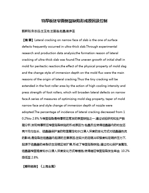
特厚板坯窄面侧裂缺陷形成原因及控制甄新刚;朱志远;王玉龙;王国连;赵晶;蒯多圣【摘要】Lateral cracking on narrow face of slab is the one of surface defects frequently occurred in ultra-thick slab.Through experimental research and production data analysis,the formation reason of lateral cracking of ultra-thick slab was found:The uneven growth of initial shell in mold for peritectic reaction,the effect of the physical property of mold slag and the change style of immersion depth on the mold flux were the main reasons of the origin of lateral cracking.Thus the tiny cracking will be extended in the foot roller area by the action of high cooling intensity and press strength of foot rollers, which will broaden lateral defects on narrow face.A series of measures of optimizing mold slag property, taper of mold narrow face and style change of immersion depth of nozzle were adopted.The percentage of incidence of lateral cracking decreased from 1 0.2%to 2.8%.%窄面侧裂是特厚板坯常发的表面缺陷之一.通过试验研究和生产数据分析,发现特厚板坯窄面侧裂缺陷的形成原因为:包晶反应使得结晶器内的初生坯壳不均匀生长、结晶器保护渣的物理属性和水口浸入深度的变化方式对结晶器热流的影响,是侧裂在结晶器内起源的主要原因;在较大的足辊冷却强度和足辊挤压力下,起源于结晶器的微裂纹在足辊区被扩展,形成了窄面侧裂缺陷.通过优化保护渣属性、结晶器窄面锥度和水口浸入深度变化方式等措施,使得铸坯窄面侧裂发生率由10.2%降低至2.8%.【期刊名称】《上海金属》【年(卷),期】2018(040)001【总页数】5页(P15-18,27)【关键词】特厚板坯;窄面侧裂;保护渣;浸入深度;锥度【作者】甄新刚;朱志远;王玉龙;王国连;赵晶;蒯多圣【作者单位】首钢京唐钢铁联合有限责任公司,河北唐山 063200;秦皇岛首秦金属材料有限公司,河北秦皇岛 066326;秦皇岛首秦金属材料有限公司,河北秦皇岛066326;首钢京唐钢铁联合有限责任公司,河北唐山 063200;秦皇岛首秦金属材料有限公司,河北秦皇岛 066326;首钢京唐钢铁联合有限责任公司,河北唐山 063200【正文语种】中文铸坯宽厚比大于3被称为板坯,连铸板坯按照厚度规格又可以分为薄带板坯、薄板坯、中板坯、厚板坯和特厚板坯。
碳样小单孢菌FIM99-663产生的新抑锈病素

碳样小单孢菌FIM99-663产生的新抑锈病素(作者:___________单位: ___________邮编: ___________)作者:连云阳谢阳魏天恩程振泰程元荣【摘要】在筛选新抗真菌抗生素过程中,从福建邵武森林土壤样品中分离得到一株对酵母样真菌有较强抗菌作用的小单孢菌FIM 99-663。
经分类鉴定为碳样小单孢菌Micromonospora carbonacea FIM 99-663。
该菌株发酵次级代谢产物含三个抗真菌活性组份,主成份为Fw99-663C组份,经提取、纯化,理化性质、光谱学分析发现它与新抑锈病素(neorustmicin)同质。
【关键词】小单孢菌;新抑锈病素;抗真菌抗生素ABSTRACT In the course of screening for new antifungal antibiotics, Micromonospora sp. FIM 99-663 was isolated from a forest soil sample collected in Shaowu, China. Based on the taxonomic data, the strain was identified as Micromonospora carbonacea FIM 99-663. The culture broth of FIM 99-663 contained A, B and C three bioactive components, and component A and Bwere traced and major component C was extracted and purified. The physico-chemical properties and spectra of component C showed it was identical with antifungal antibiotic neorustmicin.KEY WORDS Micromonospora; Neorustmicin; Antifungal antibiotic随着抗生素、激素、抗肿瘤药物、免疫抑制剂等的广泛应用和器官移植等大型手术的实施,近年来临床上深部真菌感染的发病率及其死亡率明显增加。
Comment

Ms. Ref. No.: CATCOM-D-10-00181Title: The synergistic effect of the precursors of the Cu/ZnO/Al2O3 catalysts for water-gas shift reactionCatalysis CommunicationsDear Dr Qian Li,Reviewers have now commented on your paper. You will see that they are advising a major revision of your paper. If you are prepared to undertake the work required, I would be pleased to reconsider my decision.For your guidance, reviewers' comments are appended below.If you decide to revise the work, please submit a list of changes or a rebuttal against each point which is being raised when you submit the revised manuscript.To submit a revision, please go to /catcom/ and login as an Author.Your username is: ******If you need to retrieve password details, please go to:/catcom/automail_query.aspOn your Main Menu page is a folder entitled "Submissions Needing Revision". You will find your submission record there.Yours sincerely,Angelika BrücknerEditorCatalysis CommunicationsReviewers' comments:Reviewer #1: The authors have performed a very nice study of catalysts for the WGS. There are afew things that need to be explained better in the paper.1) Bottom of page 1 and top of page 2: It is well known that the Cu particle sizeand nature of the oxide support affect the performance of the WGS catalysts (Perezet al, Angew. Chem. 2007, 46, 1329; Park et al, J. Am. Chem. Soc. 2010, 132, 356).This should be mentioned. The results in this article point to an optimization inthe performance of the oxide phase.2) Page 4, lines 16-20: Will the structure found for Cu-Zn-Al 3 survive underreaction conditions?3) Page 5, lines 5-10: For the benefit of the future reader, describe in more detailthe endothermic reactions mentioned in the text.4) Page 5, lines 44-50: In general, a two-step reduction of CuO under CO or H2 maynot occur (Wang et al, J. Phys. Chem. B, 2004, 108, 13667).5) Reading the discussion on page 7, I don't see clear why the Cu-Zn-Al 3 sample hasa higher catalytic activity.Reviewer #2: The impact of catalysts' composition on the WGS activity is studied in the paper …The synergistic effect of the precursor of the Cu/ZnO/Al2O3 catalysts for water gas shift reaction" by W. Fu et al. Despite the renewed interest in the WGSR, arising from the need of high purity hydrogen for fuel cell application, the novelty is questionable. Commercial Cu/ZnO-based WGS catalysts are not very suitable for fuel processors because they require special activation procedures, are pyrophoric, and are intolerant of poisons, condensation, and oxidation.In the Introduction the Authors don't mention that precious metal catalysts (Au, Pt) are extensively evaluated because of their better stability in oxidizing atmospheres. The application of fuel cell systems in the transportation sector involves frequent start-ups and shut-downs. The shift catalysts insmall-scale hydrogen production units are, therefore, exposed to water and/or oxygen containing atmospheres at low temperatures. Copper-based catalysts are active for the shift reaction, but are more unstable to oxidant gases than precious metals. More detailed catalytic tests in order to mimic start-up and shut-down condition could improve the paper. The comparison with the activity of commercial CuO-ZnO-Al2O3 catalyst is also relevant.The Authors have used different techniques to characterize structural and physico-chemical properties. However, due to very poor English many statements are unclear. In my opinion some figures should be presented as Supporting information, because the manuscript contains more than 5 figures. The titles of Tables and Figure captions should be presented, too.Abstract and Conclusion sections should be revised, because the statement that "eventually increases the number …." is speculative and not supported by relevant experimental data.The manuscript needs substantial improvement of the level of English. It its present form it is not acceptable for Catal. Communications. In many cases the reader has to guess what the Authors have in mind, for example, the two columns in Table 1 with data for Surface area (Precursor and Oxidation).Reviewer #3: Review Manuscript no. CATCOM-D-10-00181Title: The synergistic effect of the precursors of the Cu/ZnO/Al2O3 catalysts for water-gas shift reactionThe manuscript definitely contains some interesting data, but my advice is nevertheless a major revision. The reason for this is that some of the scientific presentation and claims need further clarification. In addition, the language still needs improvement, although the authors apparently already have undertaken some efforts to improve grammar and choice of words.Note also, that while the Figure captions seem to have been written twice in the first submission, I do not find them at all.In the following, I clarify in detail what I mean:1. Conversion data.- I do not understand the authors' basis for calculating the conversion. Why is not (COin-COout)/COin or an equivalent expression applied? In my view, their definition does not make sense. In addition, they show conversions close to or even higher than predicted by thermodynamic equilibrium for the highest reaction temperature. This tells me, that either the product analysis is of low precision or the basis of the calculation/comparison is wrong. In any case, in terms of activity may the highest temperature not be relevant for comparing the catalysts, since the reverse reaction may to a large extent take place as well.- The authors could also be somewhat more modest in their claims. Phrases claiming "perfect performance" (Page 6, line 42-42 "…the Cu-Zn-Al 3 had the perfect performance for WGSR at 483K-513K,…" Page 7, line 10 "It could be revealed that the perfect reforming performance of Cu-Zn-Al 3 was ascribed to…" ) should not be used unless much stronger evidence is given and "perfect" should then be defined in terms of activity (mol/g cat&time or TOF), selectivity, stability, cost of materials and synthesis as well an environment/health effects.- Page 6, line36-41: "For Cu-Zn-Al 3, at 453 K-513 K, the activity had the direct proportion with reaction temperature, and especially the remarkable increase was observed from 77 %-95 % at 453K-483 K." The increase in activity with temperature is expected, and the increase from 453K to 483K is not necessarily remarkable. What could be remarkable, however, is the activity at temperatures as low as 453K and 483K, but since neither were the feed flows given nor was the activity quantified in mol CO converted per time and mass of catalyst, it is difficult to judge on basis of the conversion data only. Then temperature is another important factor in Fig 6: The authors should specify how the temperature was measured, and whether there were any temperature gradients over the catalytic bed. Was the temperature measured inside the bed, or are the temperatures given measured on the outside of the reactor? If the catalyst was undiluted, the temperature over the bed should increase significantly by the heat released by the exothermic reaction, and the catalyst temperature may be significantly higher than the furnace temperature. This could in fact also explain the higher than equilibrium conversion obtained.- Finally, the authors refer to this WGS catalyst as a "reforming" catalyst several times. "Reforming" is normally used for catalytic reforming in the refinery octane upgrading processes or in connection with steam reforming and autothermal/oxidative steam reforming at high temperature (>600C). The WGScatalyst may be part of a "fuel reformer", but is usually not termed a "reforming" catalyst as such, and it leads to confusion.2. The "synergistic effect". I do not completely understand the explanation behind synergistic effect claimed by the authors. It has to be explained more carefully, being more specific on the following issues:- First of all, when claiming very special properties (i.e. "perfect") of a specific composition (12%), a comment on reproducibility of the catalyst synthesis should be made. Was the 12% Al and the other catalysts synthesized more than once, and did the same correlation between properties and Al content hold for all the batches? And did the authors measure the elemental composition of any of the catalysts, to check that the nominal composition targeted in the synthesis actually was obtained? Please also rewrite the statement on page 4: "Nishida et al [6] investigated the phase development of the precursors with Cu/Zn 1, Al 0 mol%, 5 mol%, 10 mol%, 15 mol%, 20 mol%, and 25 mol% respectively, and the structural singularity in the middle content of Al was not found in their research. The difference between our investigations was the diversity of the chosen content of Al." What do you mean by "diversity" here? In terms of Al content, you have similar "diversity", i.e. 5 different Al levels. In terms of range, they have greater "diversity" than your study; 0-25% Al vs 4-24% Al. Do you mean that the reason why they do not see the structural singularity effect is that they used 10 and 15% Al and not 12%? Then you better be sure that the "structural singularity" is caused by the Al content and not some other synthesis parameter, since several studies point to the importance of synthesis temperature, stirring rate, pH etc during this precipitation.- What is meant by the so-called "phase singularity" of Cu-Zn-Al 3? From the XRD data, it is not single phase, but shows two phases after calcination, CuO and ZnO, that are also present in the other catalysts. Do the authors mean the absence of (actually very small) hydrotalcite peaks after calcination? In the abstract (as well as in the text), it is written "It suggests that aurichalcite has been partially intercalated into hydrotalcite and assimilated the surrounding structure in precipitating, which eventually increases the number of active centers and enhances the interaction between the active centers and supporters of catalyst." Strictly speaking, the sentence does not make sense, but I interpret it as something: "It suggests that aurichalcite has been partially intercalated into the hydrotalcite and assimilated by the surrounding structure during precipitation, which eventually increases the number of active centers and enhances the interaction between the active centers and support of the catalyst." Please be more specific about how aurichalcite could be partially intercalated into the hydrotalcite (illustration?), what is meant by the surrounding structure (is it outside the hydrotalcite?) and finally how this affects the "active centers"? Considering that the CuO and ZnO crystallite sizes are more or less the same for all catalysts as measured by XRD - which effects do the authors think are crucial to the activity? Several authors have proposed the interface between Cu and ZnO. If this is what the authors suggest, they should say so more clearly. And please never write "supporters of catalyst" unless you refer to yourselves.- I also have to say that the TEM data presented has limited value in their present form, since none of the differences between the catalysts claimed by the authors can be distinguished in the attached pictures. It does not mean that I object to the findings, particularly if they are the result of studyingmany catalyst particles, only that it is hard see even from the high resolution files uploaded.3. Reduction properties and TPR. The TPR data show the reduction peak at approx 600K, while the authors reduce the catalysts at 473K before reaction. If Fig 4 is correct, the catalyst is not reduced after the reduction procedure applied. Given the apparent low temperature activity, however, it does seem to be reduced. The authors should explain this. Could it be that the TPR heating rate (10 K/min) is too fast, resulting in an apparently higher reduction temperature than the actual one. More careful TPR could give clearer differences between the catalysts, and is advised.4. Calorimetry (DSC) data. These are (if reproducible) definitely interesting. But, the authors are encouraged to focus even more on the main differences between the catalysts, and the main peaks of temperature region 2 and 4, rather than listing a large number of peaks in table 3 that are hardly possible to see in the figure. The explanation for the main peaks is plausible and supported by XRD data.5. Surface area.Page 3, line 43-46: The authors write: "It can be found that both the surface areas of precursors and mixed oxides gradually declined with the increased content of Al". From table 1, however, there is no "declining" trend in surface area for the precursor, so this should be rewritten.6. XRD. I see no reason to list both d(003) and c, since they are essentially equivalent, unless the planes separated by d(003) are discussed specifically. On page 4, line 34-39, the authors write: "The crystal instant and the interlayer distance of hydrotalcite with different content of Al are shown in Table 2. It could be seen that the increase of Al content leaded to a gradual decline in interlayer distance of hydrotalcite. However, the interlayer distance of Cu-Zn-Al 3, jumped to the maximum value. This result was well correlated with the structural analysis by XRD." What is meant by "well correlated with", since both the interlayer distances AND the structural analysis are obtained from XRD? The authors further write: "Based on the analysis of structural distribution and interlayer distance of hydrotalcite in Cu-Zn-Al 3, we could find that certain substances might be incorporated in the interlayer spacing of hydrotalcite and subsequently induced the expansion of the interlayer spacing and the weaken intensities of the diffraction lines for hydrotalcite." What is meant by certain substances here? Please be specific. Also note that it should probably read "weakened", not "weaken".7. Terminology. Authors refers to the crystalline phases exiting before calcination as "precursors". This is not necessarily incorrect, but many working in catalyst synthesis seem to refer to the salt solutions themselves as "precursors", which mean there could be confusion. Maybe "structural precursors" or similar could be used? Please also be more consistent when referring to calcination. In table 1, the surface area is given for "precursor" and "oxidation", which I presume means before and after calcination, respectively?8 The language is still incorrect, particularly in terms of words that seem to be mixed or confused. Examples include (list not complete):Page 4 line 26 and page 6, line 59, the abovementioned "diversity" in Al contentPage 1, line 43 "many attention"Page 2, line 4-5, page 5, lin 8-9: It is written "contributed to", but it appears it should have been "attributed to".Confusion between "while" and "when""Special" surface area instead of "specific""Crystal instant" instead of "crystal constant"(or even better: "lattice constant")"leaded" instead of "led"Catalyst "supporters" (!)Finally, given the vast literature on the CuZnAl catalyst system, it may well be that some more central references should be included.For further assistance, please visit our customer support site at . Here you can search for solutions on a range of topics, find answers to frequently asked questions and learn more about EES via interactive tutorials. You will also find our 24/7 support contact details should you need any further assistance from one of our customer support representatives.。
热力学大作业水-乙醇共沸分析

热⼒学⼤作业⽔-⼄醇共沸分析化⼯热⼒学结业⼩论⽂课程名称:化⼯热⼒学指导⽼师:专业班级:学⽣姓名:学号:⽇期:2012/12/31、计算101.325kpa 下,⼄醇(1)-⽔(2)体系⽓液平衡数据2、判断是否有共沸组成并计算该点组成及温度;并与⽂献数据对⽐3、怎样才能从20wt%稀酒精得到⽆⽔⼄醇以作为汽车燃料?计算⽓液平衡数据⽅法(步骤): 1、由C2H5OH 以及H2O ,查得两物质临界参数Tc1、Tc2、Pc1、Pc2、ω查得antonio ⽅程中C2H5OH 和H2O 参数A1,B1,C1,A2,B2,C2,进⼊2 2、利⽤总压强P 总=101.325kpa ,带⼊antonio ⽅程iii s i C T B A p +-=ln 得T1,T2,进⼊3 3、假设x1,x2数据,从⼩到⼤假设,并取0.01为间隔,逐次递增,由T=T1*x1+T2*x2,并另各V i初值均为1,进⼊4 4、将T 值带⼊antonio ⽅程iii si C T B A p +-=ln 可得Ps1和Ps2,进⼊5 5、选择NRTL ⽅程,计算γi ,进⼊66、利⽤两物质临界参数以及T 、P 值计算Tr1,Tr2,Prs1,Prs2,再利⽤对⽐态法(计算逸度系数的对⽐态法)计算⽓态混合物各组元i 的逸度系数,进⼊77、利⽤平衡⽅程,Vi si S i i i i P P x y ?γ?=计算y1、y2,进⼊88、计算y1+y2的值,并判断是否进⾏迭代9、将yi 归⼀化,利⽤混合物维⾥⽅程(计算混合物逸度系数的维⾥⽅程)结合混合规则计算各Vi,返回7 10、判断y1+y2是否与8的值不同,“是”返回6,“否”进⼊11 11、计算y1+y2,判断是否为1,“否”进⼊12,“是”进⼊1312、调整T 值,如果y1+y2⼤于1,则把T 值变⼩,如果y1+y2⼩于1,则把T 值变⼤,并返回413、得出T 、所有yi 值,并列出表格,进⼊1414、将所有按从⼩到⼤顺序假设的Xi 值所对应的Yi 值求出,并作出T-X-Y 图,进⼊15 15、结束x-y与温度、泡点、露点的数据X-Y图T-X-Y图从⽂献查值,常压下,⼄醇的沸点为78.1℃,⽔的沸点为100摄⽒度,⼄醇和⽔的⼆元共沸沸点为78.1摄⽒度,⼆元共沸组成:⽔4.4%,⼄醇95.5%。
利用红外光法探究赤铁矿界面铬与砷相互作用
第2期2021年4月No.2April,2021铬和砷是毒性较强的重金属,近年来,对其去除的研究较多。
赤铁矿是土壤氧化铁中最稳定的矿相,也是我国红壤、砖红壤及燥红土等高度风化的土壤中最主要和常见的氧化铁矿物。
使用赤铁矿去除Cr 和As 的研究较多,但对赤铁矿在铬和砷两者共存时的去除情况研究较少[1]。
傅里叶变换衰减全反射红外光谱法,与传统分析检测技术相比,具有原位测定、实时跟踪的优点,能同时监测多种物质的吸附[2]。
研究表明,当pH 为3、7、11时,As(Ⅲ)和Cr(Ⅵ)溶液直接混合存在于溶液中时,两者不发生反应,说明As(III)和Cr(VI)在不添加其他外来物质或不施加能量的条件下,可以在水溶液中稳定共存[3]。
有研究表明,赤铁矿对As(Ⅲ)有一定的吸附和氧化作用[4],可将As(Ⅲ)转化成毒性和迁移性更小的As(Ⅴ)[5]。
Cr(Ⅵ)为铬的高价态,可被还原成毒性和迁移性较弱的Cr(Ⅲ)[6]。
因此,本研究使用ATR-FTIR 探究赤铁矿在As(Ⅲ)和Cr(Ⅵ)共存的情况下,对两者的去除作用。
1 实验方法实验通过红外光谱法(ATR-FTIR ),探究赤铁矿对Cr(Ⅵ)的吸附和As(Ⅲ)的吸附氧化在不同时间为红外光谱的变化,反映赤铁矿对Cr(Ⅵ)的吸附和对As(Ⅲ)的吸附氧化过程。
使用红外光谱仪(Bruker VERTEX 70)流动池采集吸附态的红外光谱。
取约2 mg 赤铁矿粉末Hem 于1 mL 水中,超声使之分散均匀。
将悬浮液均匀涂抹在ATR 反应池中的ZnSe 晶体上,静置过夜,待其风干。
反应时,以0.5 mL/min 的流速通入pH 为4、0.1 mol/L NaNO 3溶液作为背景电解质,每隔5 min 采集红外光谱,1 h 后待红外光谱稳定(峰强不再增加)时,以0.5 mL/min 的速度,通入pH 为4、质量浓度为20 mg/L 的Cr(Ⅵ)溶液(内含0.1 mol/L NaNO 3),每隔2 min 采集红外图谱。
药化-3

How Do Drugs Bind to Enzymes & Receptors?
药物与酶和受体如何结合?
Drugs bind to particular sites on enzymes and receptors. In the case of an enzyme, this will often be the active site. Receptors have binding pockets formed between transmembrane helixes where drugs usually bind (not always the agonist’s binding site).
D-X-H….Y-A
O N H
e.g. R-O-H…..O=C
HO2C
CO2H
Haem group – iNOS, CYP-450
Shape Complementarity
iNOS Enzyme Inhibitor
O F H N N F NH2
+
H2 Receptor Antagonist
N
N
AZ10896372
HN
H N
S N
H N
H N CN
Cimetidine 西咪替丁 组胺 Histamine
AZ-10896372 iNOS Inhibitor
O F H N N F H N H O GLU H
+
Neuraminidase Inhibitor (Antiviral GSK)
H
N
N OH N HO OH R R O O
H
N
肥料添加剂-钙化钙剂说明书
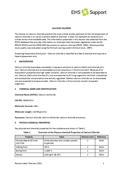
CALCIUM CHLORIDEThis dossier on calcium chloride presents the most critical studies pertinent to the risk assessment of calcium chloride in its use as a cement additive chemical. It does not represent an exhaustive or critical review of all available data. The information presented in this dossier was obtained from the ECHA database that provides information on chemicals that have been registered under the EU REACH (ECHA) and the OECD-SIDS documents on calcium chloride (OECD, 2002). Where possible, study quality was evaluated using the Klimisch scoring system (Klimisch et al., 1997).Screening Assessment Conclusion – Calcium chloride is classified as a tier 1 chemical and requires a hazard assessment only.1BACKGROUNDCalcium chloride dissociates completely in aqueous solutions to calcium (Ca2+) and chloride (Cl-) ions. Calcium chloride and its dissociated ions are ubiquitous in the environment. Because of its dissociation properties and high water solubility, calcium chloride is not expected to be adsorbed to soil. Calcium (Ca2+) and chloride (Cl-) ions are essential to all living organisms, and their intracellular and extracellular concentrations are actively regulated. Neither calcium chloride nor its dissociated ions are expected to bioaccumulate.. Calcium chloride is of low toxicity concern to aquatic organisms.2CHEMICAL NAME AND IDENTIFICATIONChemical Name (IUPAC): Calcium dichlorideCAS RN: 10043-52-4Molecular formula: CaCl2Molecular weight: 110.98 gm/molSynonyms: Calcium chloride; calcium dichloride; calcium chloride anhydrous3PHYSICO-CHEMICAL PROPERTIESKey physical and chemical properties for the substance are shown in Table 1.Table 1 Overview of the Physico-chemical Properties of Calcium ChlorideProperty Value Klimisch score ReferencePhysical state at 20o C and 101.3 kPa White odourless solid; crystals; powder;or granules2 ECHAMelting Point 782o C 2 ECHA Boiling Point >1,600 o C 2 ECHA Density 2150 kg/m3 @ 25o C 2 ECHAProperty Value Klimisch score Reference Vapour Pressure - - - Partition Coefficient (log K ow) Not applicable - - Water Solubility 745 g/L @ 20o C (very soluble) 2 ECHA4DOMESTIC AND INTERNATIONAL REGULATORY INFORMATIONA review of international and national environmental regulatory information was undertaken (Table2). This chemical is listed on the Australian Inventory of Chemical Substances – AICS (Inventory). No conditions for its use were identified. No specific environmental regulatory controls or concerns were identified within Australia and internationally for calcium chloride.Based on an assessment of environmental hazards, NICNAS identified calcium chloride as a chemical of low concern to the environment (NICNAS, 2017). Chemicals of low concern are unlikely to have adverse environmental effects if they are released to the environment from coal seam gas operations.Table 2 Existing International ControlsConvention, Protocol or other international control Listed Yes or No?Montreal Protocol NoSynthetic Greenhouse Gases (SGG) NoRotterdam Convention NoStockholm Convention NoREACH (Substances of Very High Concern) NoUnited States Endocrine Disrupter Screening Program NoEuropean Commission Endocrine Disruptors Strategy No5ENVIRONMENTAL FATE SUMMARYCalcium chloride dissociates completely in aqueous solutions to calcium (Ca2+) and chloride (Cl-) ions. Calcium chloride and its dissociated ions are ubiquitous in the environment.Because of its dissociation properties and high water solubility, calcium chloride is not expected to be adsorbed to soil. The calcium ion may bind to soil particulate or may form stable inorganic salts with sulfate and carbonate ions. The chloride ion is mobile in soil and eventually drains into the surface water because it is readily dissolved in water (OECD, 2002).Calcium (Ca2+) and chloride (Cl-) ions are essential to all living organisms, and their intracellular and extracellular concentrations are actively regulated (Ganong, 1995). Neither calcium chloride nor its dissociated ions are expected to bioaccumulate.6ENVIRONMENTAL EFFECTS SUMMARYA.SummaryCalcium chloride is of low toxicity concern to aquatic organisms.B.Aquatic ToxicityAcute StudiesTable 3 lists the results of acute aquatic toxicity studies conducted on calcium chloride.Table 3 Acute Aquatic Toxicity Studies on Calcium ChlorideReference Test Species Endpoint Results (mg/L)KlimischscorePimephales promelas 96-hour LC50 4,630 2 OECD, 2002; ECHA Lepomis macrochirus 96-hour LC509,500-11,300 2 OECD, 2002; ECHA Gambusia affinis 96-hour LC5013,400 2 OECD, 2002; ECHA Lepomis macrochirus 96-hour LC5010,650 2 OECD 2002; ECHA Daphnia magna 48-hour EC502,400 1 OECD, 2002; ECHA Daphnia magna 48-hour EC502,770 2 OECD, 2002; ECHA Ceriodaphnia dubia 48-hour EC501,830 2 OECD, 2002; ECHA Daphnia magna 48-hour EC501,062 2 OECD, 2002; ECHA Pseudokirchneriella72-hour EC50 2,900 (biomass) 1 OECD, 2002; ECHA subcapitataChronic StudiesThe 21-day EC50 and EC16 values for calcium chloride in a chronic Daphnia reproduction study were 610 and 320 mg/L, respectively (OECD, 2002).C.Terrestrial ToxicityNo studies are available.7CATEGORISATION AND OTHER CHARACTERISTIC OF CONCERNA.PBT CategorisationThe methodology for the Persistent, Bioaccumulative and Toxic (PBT) substances assessment is based on the Australian and EU REACH Criteria methodology (DEWHA, 2009; ECHA, 2008).Calcium chloride is an inorganic salt that dissociates completely to calcium and chloride ions in aqueous solutions. Biodegradation is not applicable to these inorganic ions; both calcium andchloride ions are also ubiquitous and are present in most water, soil and sediment. For the purposes of this PBT assessment, the persistent criteria are not considered applicable to this inorganic salt.Calcium and chloride ions are essential to all living organisms, and their intracellular, and extracellular concentrations are actively regulated. Thus, calcium chloride is not expected to bioaccumulate.A chronic toxicity has been conducted on calcium chloride, but an NOEC of EC10 was not determined. The acute EC50 values for calcium chloride are >1 mg/L in fish, invertebrates and algae. Thus, calcium chloride does not meet the screening criteria for toxicity.The overall conclusion is that calcium chloride is not a PBT substance.B.Other Characteristics of ConcernNo other characteristics of concern were identified for calcium chloride.8SCREENING ASSESSMENTChemical Name CAS No.Overall PBTAssessment 1Chemical Databases of ConcernAssessment StepPersistence Assessment StepBioaccumulativeAssessment StepToxicity Assessment StepRisk Assessment ActionsRequired3 Listed as a COCon relevantdatabases?Identified asPolymer of LowConcernP criteriafulfilled?Other PConcernsB criteria fulfilled?T criteriafulfilled?AcuteToxicity2ChronicToxicity2Calcium Chloride 10043-52-4 Not a PBT No No NA No No No 1 1 1 Footnotes:1 - PBT Assessment based on PBT Framework.2 - Acute and chronic aquatic toxicity evaluated consistent with assessment criteria (see Framework).3 – Tier 1 – Hazard Assessment only.Notes:NA = not applicablePBT = Persistent, Bioaccumulative and ToxicB = bioaccumulativeP = persistentT = toxic9REFERENCES, ABBREVIATIONS AND ACRONYMSA.ReferencesDepartment of the Environment, Water, Heritage and the Arts [DEWHA]. (2009). Environmental risk assessment guidance manual for industrial chemicals, Department of the Environment,Water, Heritage and the Arts, Commonwealth of Australia.ECHA. ECHA REACH database: https://echa.europa.eu/information-on-chemicals/registered-substancesEuropean Chemicals Agency [ECHA]. (2008). Guidance on Information Requirements and Chemical Safety Assessment, Chapter R11: PBT Assessment, European Chemicals Agency, Helsinki,Finland.Ganong, W.F. (1995). Review of Medical Physiology, 17th Edition, Appleton & Lange, Norwalk, Connecticut, USA.Klimisch, H.J., Andreae, M., and Tillmann, U. (1997). A systematic approach for evaluating the quality of experimental and toxicological and ecotoxicological data. Regul. Toxicol. Pharmacol. 25:1-5.NICNAS. (2017). National assessment of chemicals associated with coal seam gas extraction in Australia,Technical report number 14 - Environmental risks associated with surface handling of chemicals used in coal seam gas extraction in Australia. Project report prepared by theChemicals and Biotechnology Assessments Section (CBAS), in the Chemicals and WasteBranch of the Department of the Environment and Energy as part of the NationalAssessment of Chemicals Associated with Coal Seam Gas Extraction in Australia,Commonwealth of Australia, Canberra.OECD. (2002). OECD-SIDS: Calcium chloride (CAS No. 10043-52-4), UNEP Publications. Available at: /documents/sids/sids/10043524.pdfB.Abbreviations and Acronyms°C degrees CelsiusAICS Australian Inventory of Chemical SubstancesCOC constituent of concernDEWHA Department of the Environment, Water, Heritage and the ArtsEC effective concentrationECHA European Chemicals AgencyEU European UnionIUPAC International Union of Pure and Applied ChemistrykPa kilopascalLC lethal concentrationmg/L milligrams per litreNOEC no observed effective concentrationOECD Organisation for Economic Co-operation and DevelopmentPBT Persistent, Bioaccumulative and ToxicREACH Registration, Evaluation, Authorisation and Restriction of Chemicals SGG Synthetic Greenhouse GasesSIDS Screening Information Data Set。
Re(Ⅶ)在辐照膨润土中的扩散行为研究
Re(Ⅶ)在辐照膨润土中的扩散行为研究王芝芬;侯敏;陈钰晨;石磊;伍涛;李金英【摘要】高庙子(GMZ)膨润土在长期深地质处置过程中会受到高放废物的辐照,物理化学性质可能会发生改变.本文采用贯穿扩散实验法,研究了pH=3.0和10.0条件下,Re(Ⅶ)在1 MGy辐照的蒙脱石和膨润土中的扩散行为,并与未辐照的蒙脱石和膨润土相比较,得到了有效扩散系数De和有效孔隙率εacc.结果表明:pH=3.0时,De=(1.00~1.49)×10-11 m2/s,εacc=0.09~0.14;pH=10.0时,De=(1.50~2.10)×10-11 m2/s,εacc=0.07~0.11.随着酸度的增加,有效扩散系数和孔隙率基本不变,说明pH值对Re(Ⅶ)的扩散过程无影响.在蒙脱石中,辐照后的有效扩散系数降低;而在膨润土中,辐照后的有效扩散系数升高,这可能是由于γ辐照改变了膨润土除蒙脱石以外黏土的微观结构,有效孔隙率的增加导致Re(Ⅶ)扩散通道的宽度增加.但由于有效扩散系数和有效孔隙率的改变不大,γ辐照对Re(Ⅶ)的表观扩散系数的影响不明显.此外,De与εacc的关系可通过Archie定律表述,胶结因子n=1.7~2.4.%The physical and chemical properties of GMZ bentonite will be changed by irradiation from high level nuclear waste after long time deep geological disposal.In this study,the diffusion behaviors of Re(Ⅶ) in 1 MGy irradiation montmorillonite and bentonite were investigated by a through-diffusion method at pH=3.0 and 10.0.The results were also compared with the unirradiated montmorillonite and bentonite.The effective diffusion parameter De and accessible porosity εacc were o btained.The results show that De and εacc are (1.00-1.49)×10-11 m2/s and 0.09-0.14 atpH=3.0,while De and εacc are (1.50-2.10)×10-11 m2/s and 0.07-0.11 atpH=10.0,respectively.De and εaccremained unchanged with the increase ofpH,which indicates that pH ha s insignificant effect on Re(Ⅶ) diffusion.In case of montmorillonite,De of irradiated clay is lower than that of unirradiated one,whereas,it is higher than that of unirradiated bentonite.It is probably because of that the component of bentonite exceptmont morillonite may change by the γ-irradiation.The increase of εacc indicates that the diffusion path of Re(Ⅶ) is broaden.However,γ-irradiation has no obvious effect on Da because of the minor change of both De and εacc.Moreover,the relationship of De and εac c can be described by Archie's law with exponent n=1.7-2.4 for ReO-4.【期刊名称】《原子能科学技术》【年(卷),期】2017(051)004【总页数】5页(P617-621)【关键词】Re(Ⅶ);扩散;辐照;蒙脱石;高庙子膨润土【作者】王芝芬;侯敏;陈钰晨;石磊;伍涛;李金英【作者单位】湖州师范学院工学院,浙江湖州 313000;中国原子能科学研究院,北京 102413;湖州师范学院工学院,浙江湖州 313000;湖州师范学院工学院,浙江湖州 313000;中国核工业建设集团公司,北京 100037;湖州师范学院工学院,浙江湖州 313000;中国原子能科学研究院,北京 102413;华润新能源控股有限公司,北京100005【正文语种】中文【中图分类】O614.352利用深层地质处置库处置高放废物是国际公认的最有效的方法之一。
黄声骏国籍从事专业工业催化
姓名黄声骏性别男出生年月 1979年4月出生地江西婚姻状况已婚政治面貌团员国籍中国从事专业工业催化现工作单位及职位北海道大学触媒化学研究中心人事关系所在单位大连市人才中心学习及工作经历:(从大学开始填,内容包括时间、单位、学位、所学专业、从事专业、专业技术职务情况,时间段要连续,准确到月份)1996年9月-2000年6月赣南师范学院化学系,学士学位,化学2000年9月-2006年6月大连化学物理研究所,工业催化,硕博课程连读,博士学位2006年7月-2007年2月大连化学物理研究所,工业催化,临时研究人员“1-丁烯歧化反应制丙烯”2007年3月-现在北海道大学触媒研究中心,触媒化学,博士后“CO选择性氧化高活性催化剂的研制及介孔二氧化硅催化机制的研究”如内容较多,本栏目填不下时,可另纸接续(下同)。
主要学术成就、科技成果及创新点:本人主要在分子筛催化及介孔材料合成及其催化应用进行了多方面的研究。
主要包括:1.氢气中一氧化碳的选择性氧化消除(preferentional oxidation of carbon monoxide in excess hydrogen, PROX)是提供清洁氢燃料的一个重要催化过程。
由石化资源所生产的氢气经水煤气变换初步纯化过程后仍剩余的0.5-1 vol%的CO杂质,需要PROX反应深度纯化降至ppm级。
博士后工作期间,主要利用Pt/介孔二氧化硅催化体系针对该反应进行了研究。
首先在FSM型 (Folder sheets mesoporous material) 和SBA-15型介孔氧化硅载体上发现了明显的孔径效应,在比表面接近(~1000 m2/g)、负载Pt分散度接近的情况下,孔径对催化剂的催化性能有决定性的影响:孔径在2.7~4.0 nm的介孔FSM氧化硅具有较高的催化活性,较小孔径(< 2nm)和大孔径(> 7 nm)载体上的催化剂性能均出现明显的降低。
- 1、下载文档前请自行甄别文档内容的完整性,平台不提供额外的编辑、内容补充、找答案等附加服务。
- 2、"仅部分预览"的文档,不可在线预览部分如存在完整性等问题,可反馈申请退款(可完整预览的文档不适用该条件!)。
- 3、如文档侵犯您的权益,请联系客服反馈,我们会尽快为您处理(人工客服工作时间:9:00-18:30)。
J Electroceram(2006)17:835–839DOI10.1007/s10832-006-9334-1The effect of the physico-chemical properties of cellulosic polymers on the Si wafer polishing processSang-Kyun Kim·Ye-Hwan Kim·Ungyu Paik·Takeo Katoh·Jea-Gun ParkReceived:29June2005/Revised:15May2006/Accepted:26May2006CSpringer Science+Business Media,LLC2006Abstract Cellulosic polymers were used as organic addi-tives to reduce the wafer surface roughness during the polish-ing process.The physico-chemical affinity of the polymer for the wafer and the formation of a hydro-plane on the Si wafer surface were investigated to identify the role of the poly-meric additives in the wafer-polishing process.Two different polymers,hydroxyethyl cellulose(HEC)and carboxymethyl cellulose(CMC),were employed as a surface modifier for the wafer.The wettability of the Si surface varied markedly between the different suspensions prepared with HEC and CMC due to different adsorptive behaviors.As a result,the suspension prepared with HEC reduced the haze level and micro-roughness of the wafer,enhancing overall polishing performance.Keywords CMP.Wafer polishing process.Cellulosic polymers.Micro scratch.Topography1IntroductionThe development of the next generation LSI devices now re-quires smaller device dimensions below50nm.To achieve multilevel-interconnections,a wide range of global pla-narization is required to attain a sufficient depth of focus (DOF)with the process margin of exposure equipment for the fine patterns of process technology[1,2].The manufacture S.-K.Kim·Y.-H.Kim·U.Paik( )Division of Advanced Materials Science Engineering,Seoul133-791,Koreae-mail:upaik@hanyang.ac.krT.Katoh·J.-G.ParkNano-SOI Process Laboratory,Hanyang University,Seoul133-791,Korea of semiconductor devices is significantly affected by the sur-face roughness of the Si wafer.Chemical mechanical pla-narization(CMP)is one of the key processes used for the planarization of the wafer surface[3–5].In the wafer polishing process,slurry conditions are crit-ical for the acquisition of high quality planarized wafers through chemical and mechanical interactions.However,pol-ishing slurries include abrasives which cause severe damage to the wafers after polishing.The problems commonly found in thefinal CMP process include surface scratching,polish-ing haze and residual particles[6–11].These defects gener-ated during the CMP process,including pin-holes,a lower punch-through voltage and the increase of current leakage, can directly influence the electrical characteristics and pro-ductivity of the devices in ULSI.In the wafer polishing process,the improper contact of abrasive particles on the wafer surface inevitably induces micro-scratches and a rugged topography on the wafer sur-face.Generally,organic additives such as cellulosic polymers have been used to resolve these problems.The formation of a hydro-plane resulting from the physico-chemical affinity of these polymeric molecules for the wafer is a key factor in a successful wafer polishing process[12].This hydro-plane prevents the direct contact of the abrasive on the wafer surface,and thus the polishing is conducted primarily by a chemical reaction and only indirectly by mechanical re-moval.Consequently,the interaction between the polymeric additives and wafer surface should be understood in order to manipulate the interaction force between the abrasive and the wafer surface.In this study,two different colloidal silica slurries were prepared containing two cellulosic polymers,hydroxyethyl cellulose(HEC)and carboxymethyl cellulose(CMC).The effect of the physico-chemical properties of cellulosic poly-mers on the wafer polishing process was investigated withthe aim of reducing roughness,micro-roughness,and haze on the wafer surface after polishing.2Experimental procedureNanometer-sized colloidal silica(PL-3,Fuso chemical Inc., Japan)was used in the present investigation.Three different colloidal silica slurries were prepared with hydroxyethyl cel-lulose(HEC)(Mw=25000–30000,Polysciences,U.S.A.) and carboxymethyl cellulose(CMC)(Mw=25000–30000, Polysciences,U.S.A.).The slurries were composed of0.4 wt%HEC,0.4wt%CMC,and a combination of0.2wt% HEC and0.2wt%CMC.The solid content of the suspension wasfixed at a weight fraction of10%.Suspension pH was adjusted to10using a1M ammonium hydroxide solution.The surface tension of the0.4wt%cellulosic polymer suspensions,which were prepared at pH10,was measured by a dynamic contact angle analyzer(DCA)(DCA-312,CAHN Instruments,Inc.,U.S.A.).The contact angle was measured by a drop shape analysis system(DSA)(FTA100,First Ten Angstroms,Inc.,U.S.A.).The contact angle measurement was obtained by the sessile drop method[13].To analyze the adsorption behavior of the cellulose-based polymer on the Si wafer,force-separation measurements were conducted using a commercial multimode atomic force microscope(AFM)(XE-150,PSIA Inc.,Seoul,Korea).A contact mode Si cantilever was used for investigating the interactinon forces of the bare AFM tip.To test wafer polishing,8-inch wafers were used after the stock polishing process.A diluted slurry was used for wafer polishing,with thefinal solid contentfixed at a weight fraction of0.3%.Polishing was performed on a Strasbaugh model6EC polisher with a single polishing head and a pol-ishing platen which used a Cegal pad(Toray Coatex Co., Japan).The polishing pressure,applied as a down force,was 3psi(pounds per square inch)and the back pressure was0 psi.The rotation speed of both the head and the table was 60rpm.Theflow rate was200cm3/min and the polishing time was5min.The surface roughness before and after pol-ishing was measured by AFM and an interferometric surface profiler(MP-2200,Chapman).The wafer surface haze was measured by a surfscan SP1(KLA-Tencor,U.S.A.).3Results and discussionThe surface tension(γ),wetting angle(θ),and spreading coefficient(S LS)of the cellulosic polymer suspensions are listed in Table1.Wettability can be quantitatively evaluated by the spreading coefficient,which is the energy difference between the solid substrate and the contacting liquid phase.It is well known that a large spreading coefficient indicates highTable1Surface tensions(γ),contact angles(θ)and spreadingcoefficients(S LS)of the cellulosic polymer suspensionsSuspensionsγ(dynes/cm)θ(degree)S LS(dynes/cm)DIW(H2O)73.1331.50−10.77HEC40.218.15−1.99CMC68.3229.22−8.68HEC+CMC53.5224.13−4.67 wettability.The wettability of the HEC solution was larger than that of de-ionized water and CMC.This phenomenon was due to the difference in the physicochemical properties of the cellulosic polymers.HEC is prepared by substituting OC2H4OH for hydroxyl groups(OH)in cellulose which consisted of a repeating structure of glucose and three re-placeable hydroxyl groups for each unit.Its functional group is a nonionic hydroxyl group.CMC is produced by reacting cellulose with sodium chloroacetate(ClCH2COONa).Its functional group is COOH which is ionized to COO−and Na+in aqueous solutions[14].Differences in the polymeric functional groups can result in different polymer adsorption behaviors on the wafer surface.When the wafer polishing was performed at alkaline pH,the Si surface had a negative charge[15].Due to the dissociation of the carboxylic acid groups,CMC presented a negative charge at alkaline pH. Therefore,the adsorption of CMC on the Si wafer surface was retarded by the presence of repulsive forces between negatively charged carboxyl group and negatively charged Si wafer surface.On the other hand,HEC can be adsorbed on the Si wafer either through hydrophobic interactions or through hydrogen bonding due to the fact that the hydroxyl group in the HEC was a non-dissociated ionizable functional group.Accordingly,nonionic polymers decreased the surface tension and enhanced wettability on the Si surface through polymer adsorption.These results are in general agreement with results reported previously[16,17]that describe an enhancement of wettability by the addition of polymeric sur-factants.The force-separation profile between the AFM tip and Si wafer was measured to analyze the interaction force between the cellulosic polymer and the Si wafer surface(Fig.1).It is well known that the Si surface has a negative charge at alkaline pH[15].As expected,it was shown that a repulsive force due to electrostatic interactions occurred between the bared Si wafer and the AFM Si tip at pH10.The range of interaction was about30nm.It is of interest that there was no significant difference of the surface forces between the tip andfilm,even in the presence of CMC,which indicated that as a result of the electrostatic repulsion between CMC and the Si wafer surface,CMC was only slightly adsorbed onto the Si wafer surface.At alkaline pH,the carboxylic acid of CMC is almost fully ionized and CMC has an extended-chain configuration[18].Therefore,it was suggested that the510F o r c e (n N )Separation (nm)Fig.1The force-separation profile between the AFM tip and Si wafer0.00.20.40.60.81.0slurriesh a z e (p p m a )Fig.2The ppma value after touch polishing measured by SP1formation of a hydro-plane on the Si wafer surface did not take place using the suspension prepared with CMC.In the case of HEC,a substantial change in the interac-tion forces between the Si wafer and AFM Si tip was ob-tained.The repulsive force apparently dissipated and then a weak attractive force appeared.This indicated that the max-imum attractive separation force was about 0.5nN at 5nm of separation.It was reported that poly(vinyl alcohol)(PV A)is adsorbed onto Si 3N 4or SiO 2,and the primary adsorption sites are silanols (Si OH)[19–21].For PV A adsorption ontoFig.3The surface roughness of the wafer after touch polishing;(a)Rms values after touch polishing measured by chapman and(b)The surface roughness profile of the AFM imagesSiO2,the deprotonation of Si OH is proposed.The adsorp-tion behavior of HEC on the wafer was believed to be similar to the adsorption of PV A on SiO2,because both polymeric molecules have the same hydroxyl functional groups.Thus,HEC could be adsorbed on the Si wafer via hydrogen bond-ing,leading to a decreased net surface charge,due to the shielding of the surface charge by HEC[20].In the case of a mixture of CMC and HEC,the interaction force measuredwas between the values obtained for CMC and HEC alone.Figure2shows the haze level of the wafer surface as a function of cellulosic polymer.The haze level indicating the surface roughness results in background scattering noise.The values of the dark narrow normal(DNN)and the dark wide normal(DWN)channels were calculated by a laser scatter-ing tool.The signal levels of the DNN and DWN channels corresponded to a longer and a shorter wavelength compo-nent of surface roughness,respectively.The suspension of CMC did not improve the haze compared to the raw wafer surface,while the suspension containing HEC had the lowest haze value amongst the slurries used.The adsorbed HEC on the wafer surface prevented silicon dissolution and the im-proper contact of the abrasive;thus,the surface roughness was reduced after polishing.In addition,the surface roughness of the wafer after touch polishing was measured by chapman and AFM.As shown in Fig.3(a),these results gave conclusive evidence of the effect that the adsorption of the cellulosic polymer has on the wafer polishing process.Analyses were performed over the follow-ing wavelength regions:(a)1–25μm(a short wavelength), (b)25–80μm(a medium wavelength)and(c)80–250μm(a long wavelength).For each wavelength range,the suspen-sion containing the HEC exhibited excellent surfaceflatness, which correlated well with the haze profiles.In Fig.3(b),the suspension containing HEC resulted in high surface planarity as a result of AFM.Consequently,it can be concluded that the hydro-plane layer on the wafer surface,which was formed by HEC,suppresses the mechanical polishing of silicon wafer.4ConclusionsThe effect of the physico-chemical properties of the cellu-losic polymer on the wafer polishing process was investi-gated.The surface wettability of the Si wafer was enhanced by the adsorption of HEC as a nonionic polymer.However, CMC as an anionic polymer was hardly adsorbed on the sur-face due to the repulsive force between the CMC and the Si wafer surface.This resulted in a low wettability of the Si wafer for CMC suspensions.The suspension prepared with HEC yielded a high planarity-surface profile for the wafer after the polishing process.The formation of a hydro-plane by the adsorption of the polymeric additive on the Si wafer was determined to be a key factor for the successful wafer polishing.References1.S.Wolfe,Silicon Processing(Lattice Press,CA,2002),p.313.2.S.K.Kim,U.Paik,S.G.Oh,Y.K.Park,T.Katoh,and J.G.Park,Jpn.J.Appl.Phys.,42,1227(2003).3.C.Teichert,J.F.Mackay,D.E.Savage,gally,M.Brohl,andP.Wagner,Appl.Phys.Lett.,66(18),2346(1995).4.C.F.Lin,W.T.Tseng,and M.S.Feng,J.Electrochem.Soc.,146(5),1984(1999).5.S.Sivaram,H.Bath,R.Leggeti,A.Maury,K.Monnig,and R.Tolles,Solid State Technol.,35–5,87(1992).6.T.Detzel,S.Hosali,A.Sethuraman,J.F.Wang,and L.Cook,inthe CMP-MIC Conference(Institute for Microelectronics Inter-Connection,Tampa,1997),p.202.7.G.B.Basim,J.J.Adler,U.Mahajan,R.K.Singh,and B.M.Moudgil,J.Electrochem.Soc.,147,3523(2000).8.R.K.Singh,S.M.Lee,K.S.Choi,G.B.Basim,W.Choi.,Z.Chen,and B.M.Moudgil,Mater.Res.Bull.Oct.,752(2002).9.T.L.Neo,E.S.Y.Shang,and C.M.Chong,in Int.Symp.Semicon-ductor Manufacturing(The Institute of Electrical and Electronics Engineers,California,2001)p.321.10.Y.J.Seo,G.U.Kim,and W.S.Lee,Microelectronic Eng.,71,209(2004).11.J.P.Kim,U.Paik,Y.G.Jung,T.Katoh,and J.G.Park,Jpn.J.Appl.Phys.,41,4509(2002).12.W.-M.Lee,T.Katoh,H.-G.Kang,J.-G.Park,U.Paik,and H.Jeon,J.Kor.Phys.Soc.,44(4),796(2004).13.A.W.Adamson and A.P.Gast,Physical Chemistry of Surfaces(Wiely,New York,1997).14.R.Moreno,Ceram.Bull.,71,1647(1992).15.V.A.Hackley,J.Am.Ceram.Soc.,80(9),2315(1997).16.W.T.Tseng,P.L.Kuo,C.L.Liao,R.Lu,and J.F.Lin,Electrochem-ical and Solid-State Letters,4,42(2001).17.R.S.Faibish,W.Yoshida,and Y.Cohen,J.Colloid Interface Sci.,256,341(2002).18.S.-K.Kim,S.Lee,U.Paik,T.Katoh,and J.-G.Park,J.Mater.Res.,18(9),2163(2003).19.V.A.Hackely,U.Paik,B.H.Kim,and S.G.Malghan,J.Am.Ceram.Soc.,80,1781(1997).20.U.Paik,V.A.Hackley,and H.Lee,J.Am.Ceram.Soc.,82,833(1999).21.Th.F.Tadros,J.Colloid Interface Sci.,64,36(1978).。